EP3020546A1 - Piece moulee de construction legere en sandwich et son procede de fabrication - Google Patents
Piece moulee de construction legere en sandwich et son procede de fabrication Download PDFInfo
- Publication number
- EP3020546A1 EP3020546A1 EP15003230.8A EP15003230A EP3020546A1 EP 3020546 A1 EP3020546 A1 EP 3020546A1 EP 15003230 A EP15003230 A EP 15003230A EP 3020546 A1 EP3020546 A1 EP 3020546A1
- Authority
- EP
- European Patent Office
- Prior art keywords
- cover
- profile
- sandwich
- molded part
- lightweight
- Prior art date
- Legal status (The legal status is an assumption and is not a legal conclusion. Google has not performed a legal analysis and makes no representation as to the accuracy of the status listed.)
- Granted
Links
Images



Classifications
-
- B—PERFORMING OPERATIONS; TRANSPORTING
- B32—LAYERED PRODUCTS
- B32B—LAYERED PRODUCTS, i.e. PRODUCTS BUILT-UP OF STRATA OF FLAT OR NON-FLAT, e.g. CELLULAR OR HONEYCOMB, FORM
- B32B3/00—Layered products comprising a layer with external or internal discontinuities or unevennesses, or a layer of non-planar shape; Layered products comprising a layer having particular features of form
- B32B3/10—Layered products comprising a layer with external or internal discontinuities or unevennesses, or a layer of non-planar shape; Layered products comprising a layer having particular features of form characterised by a discontinuous layer, i.e. formed of separate pieces of material
- B32B3/12—Layered products comprising a layer with external or internal discontinuities or unevennesses, or a layer of non-planar shape; Layered products comprising a layer having particular features of form characterised by a discontinuous layer, i.e. formed of separate pieces of material characterised by a layer of regularly- arranged cells, e.g. a honeycomb structure
-
- B—PERFORMING OPERATIONS; TRANSPORTING
- B32—LAYERED PRODUCTS
- B32B—LAYERED PRODUCTS, i.e. PRODUCTS BUILT-UP OF STRATA OF FLAT OR NON-FLAT, e.g. CELLULAR OR HONEYCOMB, FORM
- B32B15/00—Layered products comprising a layer of metal
- B32B15/04—Layered products comprising a layer of metal comprising metal as the main or only constituent of a layer, which is next to another layer of the same or of a different material
-
- B—PERFORMING OPERATIONS; TRANSPORTING
- B32—LAYERED PRODUCTS
- B32B—LAYERED PRODUCTS, i.e. PRODUCTS BUILT-UP OF STRATA OF FLAT OR NON-FLAT, e.g. CELLULAR OR HONEYCOMB, FORM
- B32B21/00—Layered products comprising a layer of wood, e.g. wood board, veneer, wood particle board
- B32B21/04—Layered products comprising a layer of wood, e.g. wood board, veneer, wood particle board comprising wood as the main or only constituent of a layer, which is next to another layer of the same or of a different material
-
- B—PERFORMING OPERATIONS; TRANSPORTING
- B32—LAYERED PRODUCTS
- B32B—LAYERED PRODUCTS, i.e. PRODUCTS BUILT-UP OF STRATA OF FLAT OR NON-FLAT, e.g. CELLULAR OR HONEYCOMB, FORM
- B32B27/00—Layered products comprising a layer of synthetic resin
- B32B27/06—Layered products comprising a layer of synthetic resin as the main or only constituent of a layer, which is next to another layer of the same or of a different material
- B32B27/08—Layered products comprising a layer of synthetic resin as the main or only constituent of a layer, which is next to another layer of the same or of a different material of synthetic resin
-
- B—PERFORMING OPERATIONS; TRANSPORTING
- B32—LAYERED PRODUCTS
- B32B—LAYERED PRODUCTS, i.e. PRODUCTS BUILT-UP OF STRATA OF FLAT OR NON-FLAT, e.g. CELLULAR OR HONEYCOMB, FORM
- B32B5/00—Layered products characterised by the non- homogeneity or physical structure, i.e. comprising a fibrous, filamentary, particulate or foam layer; Layered products characterised by having a layer differing constitutionally or physically in different parts
- B32B5/18—Layered products characterised by the non- homogeneity or physical structure, i.e. comprising a fibrous, filamentary, particulate or foam layer; Layered products characterised by having a layer differing constitutionally or physically in different parts characterised by features of a layer of foamed material
Definitions
- the invention relates to a lightweight molded part in sandwich construction according to the preamble of claim 1 and a method for its production according to claim 11.
- Such lightweight molded parts in sandwich construction are used primarily for furniture parts in vehicle construction, especially for furniture parts in caravans and motorhomes.
- Such lightweight moldings can therefore also be used for all land, water and air vehicles in which the lowest possible weight per unit area should be achieved.
- This insert is a supporting element, which z. B. consists of a wooden plate, a chipboard or other wood material.
- the fitting receiving bore is mounted in the region of the lightweight molding plate in which the bearing insert is arranged. In this way, it should be ensured that the fitting part is mounted load-transmitting on the lightweight mold plate.
- the supporting inner part or the supporting insert should therefore serve for load transmission of fittings attached thereto and the like.
- the US 2011/0135862 A1 shows a lightweight sandwich-shaped molding in which a sandwich plate consists of two mutually parallel cover plates, between which at least partially a non-supporting center layer is arranged, with the non-supporting center layer up to the longitudinal edges of the sandwich plate on the extends over the entire area.
- the document thus discloses only a rail-like insert between the mutually parallel cover plates, but not a number of point present dowels, which take over the function of the insert, but are only available point by point and therefore suitable as a load-transfer fastening for the screws of fittings.
- the invention is therefore the object of developing a lightweight molded part of the type mentioned so that high-load-transmitting
- Attachment points can be mounted in the sandwich panel without increasing the basis weight of the sandwich panel.
- the invention therefore aims to omit the previously necessary and arranged in the space between the arranged at a distance from each other cover plates deposits.
- the invention is characterized by the technical teaching of claim 1.
- the invention consists in the fact that in the case of a sandwich panel which consists of two mutually parallel cover plates, between which a non-bearing central layer is arranged, according to the invention the non-supporting central layer extends up to the longitudinal edges of the sandwich panel over its entire surface seen extends, so that the entire space of the sandwich plate is filled by a non-supporting center layer.
- the weight-increasing deposits are thus eliminated.
- the invention provides that at least one dowel is used for fastening fittings and that when using multiple dowels each dowel passes through the middle layer and is connected with its outer surfaces with the two, spaced-apart cover layers.
- connection between the two opposite and mutually parallel cover plates is not formed by insert parts, but immediately by pointwise distributed over the surface of the cover plates arranged dowels, which have the advantage that they at the same time fastening means for a load-transfer fastening of fittings or form the same.
- An anchor is a component used in connection technology. It is used for materials where a screw can not be screwed directly. Originally, a dowel was understood to mean only the wooden dowel still used in carpentry and joinery. Sometimes the term screw anchor is used to distinguish it from the latter, which is also the subject of the invention.
- the screw forms a counter thread in the inner part of the plug, wherein it plastically deforms the plug material and additionally displaces radially outward, it spreads the plug.
- Open spaces on uneven or porous perforated walls are filled by the dowel material, whereby a positive connection is formed against pulling out of the hole in the cover plate. Mainly, however, this connection is force or friction.
- the radial forces generated in the dowel material mainly lead to its elastic radial deformation.
- the elastic forces act on the unyielding top wall as a normal force, which perpendicularly results in a proportional static friction force.
- the elastic hollow cylinder between the screw and the top wall is thick enough that the radial forces are distributed evenly on a possibly uneven hole in the top wall. At the outer edge of the hole, the radial forces steadily decrease, so that the hole in the top wall does not fray or deform.
- a dowel is integrated load-bearing in the internal structure of the sandwich panel, which is not connected to the supporting non-supporting center layer, but bridges this center position, passes through and only with its bottom surface on the inside of the a cover layer and is fastened with its peripheral surfaces on the inside of the opposite cover layer.
- a preferred embodiment of the attachment of such a dowel in the middle region of a sandwich plate is that the dowel is designed as a friction-welding dowel.
- it is vibrated with a suitable ultrasonic resonator in such a way that both its plastic base surface and the peripheral surfaces liquefy for a short time and thus form a heat-melting adhesive bond both on the surface Enter inside of a cover layer as well as on the opposite cover layer.
- the dowel is thus welded by ultrasound to the bottom surface.
- the dowel is connected by a friction welding process in the space between the two cover layers, and indeed load-transferring with two cover layers.
- the non-supporting center layer is formed of a very lightweight material, such as.
- a foamed plastic a Styrofoam, a honeycomb structure made of cellulose or plastic material and the like.
- the dowel may be secured to the two opposing top layers with a thermosetting two-component plastic or a thermofusible adhesive. It can also be combined with each other the three types of attachment described.
- the invention provides for a further feature that in the region of the longitudinal edges a supporting profile cover is arranged, which connects the two cover layers end-to-end, so that a compression of the two mutually spaced parallel cover layers in the longitudinal edge region is avoided.
- the bridging of the longitudinal edges is effected by a cover, which is at least in the region of a folding edge material integral with a cover layer and which is bendable or pivotable in the region of this fold edge, so that it is to close the L jossbekantung is simply pivoted by 90 °, so that there is an absolutely secure, load-transferring bridging the LCodeskekantitch.
- the invention is not limited to the arrangement of a one-sided connected via a folding edge with a cover layer cover profile.
- the cover profile is not connected on one side via a folding edge with the cover layer, but that the cover is placed as a separate profile piece for bridging the Leksbekantung on this Leksbekantung and welded or glued.
- the cover is connected on one side pivotally connected to the one cover layer and is pivotally connected via said folding edge with this cover layer.
- the advantage is achieved that in a single operation, a supporting, the end faces forming cover profile is created, which consists of the material of the cover plate and thus bridges the longitudinal edge load-transferring, so that it is no longer compressible.
- the cover profile is not flat, but a certain - having an enlarged surface - profile surface which forms an enlarged adhesive surface due to their increased area, so that it now For the first time it is possible to form an enlarged adhesive surface for gluing an edgebanding edge in the area of this widened profile surface.
- a profiled longitudinal edge cover is created, which has an enlarged profile surface, so that particularly well adheres to the enlarged profile surface of the edge band and can not be peeled off from the front side.
- a sandwich plate in the field of a production line can be made by successively connected manufacturing stations, because it is sufficient after milling the Lijnsbekantept to unilaterally turn over there with a covering plate cover profiles and connect to the front side by a bond, after which the Edge band is applied.
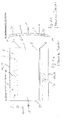
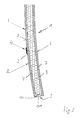
- FIGS. 1 and 2 show a sandwich plate, which consists essentially of two mutually spaced-apart cover plates 7, between which a non-supporting center layer 8 made of a compressible material, such.
- a non-supporting center layer 8 made of a compressible material, such.
- the sandwich plate z In a preferred embodiment, the sandwich plate z. Example, a thickness of 15 mm and each cover plate 7 has a thickness of 3 mm, so that the central layer has about 9 mm.
- the material of the cover plate is a single-layer plastic. However, it can also be a plastic composite material in which a layer of plastic is covered with additional covering or decorative films. Instead of a plastic plate and real wood panels, veneers, light metal materials or composite structures can be provided from one or more of the materials mentioned.
- the sandwich panel 1 is shown as a curved lightweight panel and has a front visible side 2 and a rear 6, wherein in the area of the visible side as an embodiment is still shown that a butt joint 3 is present, which covered by a Abdeckkeder 4 is.
- butt joint 3 is arranged in the region of the visible side and is covered with a Abdeckkeder 4.
- Such a joint 3 may arise when the visible side of the cover plate 7 is not formed continuously, but collides in the region of the butt joint 3 with an adjoining cover plate. In this case, this must resulting butt joint 3 are bridged with a Abdeckkeder 4 load transfer, in order to avoid an inadmissible opening of the butt joint 3 under load of the sandwich plate.
- the sandwich panel 1 has longitudinal longitudinal edges 32 opposed to each other, and the processing direction 33 is drawn from left to right as an example.
- the invention provides that in the upper region of the sandwich plate 1 receiving holes 5 are arranged, which are formed by dowels 23, whose function with reference to the later FIG. 6 will be explained.
- FIGS. 1a and 2a it is important to FIGS. 1a and 2a in that the inserts 34 belonging to the prior art can now be dispensed with. These inserts 34 are therefore intended to illustrate only the prior art, and they are completely omitted according to the invention, so that it is provided that the gap between the two cover plates 7 occupying a mutual distance from each other is formed by a non-supporting, compressible central layer 8.
- FIG. 3 shows an enlarged section through the arrangement according to FIG. 2 where it can be seen that the butt joint 3 is bridged by the Abdeckkeder 4, and further it can be seen that the Leksbekantung 32 is formed on both end faces 9 by a cover 11 which pivotally connected via a folding edge 10 with the front, visible cover plate 7 is.
- the invention is not limited thereto. It can also be provided that the folding edge 10, which forms the composite material with the front, visible cover plate 7, instead, is arranged on the rear cover plate 7.
- the profile 11 is connected either to the visible cover plate 7 or to the rear cover plate 7.
- FIG. 4 shows as an example of a preferred processing in the direction of rotation 16 about the rotation axis 17 rotatably driven cutter 18, the milling head now milled out the Leksbekantung 32 in one piece by passing in the processing direction 33 along the Leksbekantung 32 on the sandwich plate.
- the processing takes place in such a way that the material is worked out from the longitudinal edge of the sandwich panel so as to produce a cover profile 11 which is connected in one piece to the one cover panel 7 and is materially connected to it via a folding edge 10.
- cover 11 is not formed as a narrow strip, but approximately in the middle region has an enlarged profile surface 14, to each of which a narrower web profile 13 adjoins the edge.
- a profile surface 14 is formed with an enlarged adhesive surface.
- cover 11 it is manufactured according to FIG. 5 pivoted in the direction of arrow 24 by 90 °, so that the previous counter profile 15 is now completely covered load-transfer in the area of the front side 9 of the sandwich panel 1.
- the cover 11 is then in the range of Web profiles 13 connected by an adhesive or welded connection with the front side of a cover profile 7.
- cover 11 is formed from the material of the relatively stiff cover plate 7, so that thus a load-transmitting connection between the one cover plate 7 and the opposite cover plate 7 is created. This prevents that the two cover plates can be compressed in the end face area, because this by the supporting cover 11 in accordance with the front side area FIG. 5 is avoided.
- Fill receiving bores 5 form fit, and further it is essential that the bottom surface 25 is seated on the inside of the visible side cover plate 7.
- weight-increasing inserts 34 can be dispensed with and nevertheless high-load-transmitting fastening point can be achieved by using dowels 23.
- the dowel 23 is thus fixed with its bottom surface 25 with the inside of the visible cover plate 7 and fixed with its holding surface 26 which is arranged in the peripheral region of the dowel 23 in the region of the receiving bore 5 in the rear cover plate 7.
- the cover plate previously referred to as the visible cover plate 7 may also be the back cover plate, so that it is possible to form the dowel 23 also with receiving bores 5 which are open towards the visible side.
- FIG. 7 shows a milling head 27 according to the invention, which generates by means of a profile tip 29 a special milling profile 28 such that in a single milling operation, the cover 11 is machined from the material of a cover plate 7 and only about a folding edge 10th remains connected to this cover plate 7.
- the milling head 27 is guided in the direction of arrow 19 against the profile and at the same time in the vertical direction to the drawing plane FIG. 7 emotional.
Landscapes
- Life Sciences & Earth Sciences (AREA)
- Engineering & Computer Science (AREA)
- Wood Science & Technology (AREA)
- Connection Of Plates (AREA)
Applications Claiming Priority (1)
| Application Number | Priority Date | Filing Date | Title |
|---|---|---|---|
| DE102014016744.5A DE102014016744A1 (de) | 2014-11-12 | 2014-11-12 | Leichtbau-Formteil in Sandwich-Bauweise |
Publications (2)
| Publication Number | Publication Date |
|---|---|
| EP3020546A1 true EP3020546A1 (fr) | 2016-05-18 |
| EP3020546B1 EP3020546B1 (fr) | 2019-01-09 |
Family
ID=54557202
Family Applications (1)
| Application Number | Title | Priority Date | Filing Date |
|---|---|---|---|
| EP15003230.8A Active EP3020546B1 (fr) | 2014-11-12 | 2015-11-12 | Piece moulee de construction legere en sandwich et son procede de fabrication |
Country Status (2)
| Country | Link |
|---|---|
| EP (1) | EP3020546B1 (fr) |
| DE (1) | DE102014016744A1 (fr) |
Cited By (1)
| Publication number | Priority date | Publication date | Assignee | Title |
|---|---|---|---|---|
| CN106956492A (zh) * | 2017-03-22 | 2017-07-18 | 哈尔滨工业大学 | 一种高性能热塑性复合材料点阵夹芯平板及其制备方法 |
Citations (3)
| Publication number | Priority date | Publication date | Assignee | Title |
|---|---|---|---|---|
| DE2939877A1 (de) * | 1979-10-02 | 1981-05-07 | Walther Ing.(grad.) 4952 Porta Westfalica Schröder | Sandwich-verbundplatte |
| US20100135862A1 (en) | 2007-08-06 | 2010-06-03 | Hyung No Yoon | Thermowell compound apparatus of high shell for residue hydrogen desulfurization |
| US20110135862A1 (en) | 2008-04-30 | 2011-06-09 | Takehiko Sumi | Core material for sandwich panel, method of molding core material for sandwich panel, sandwich panel, and method of molding sandwich panel |
-
2014
- 2014-11-12 DE DE102014016744.5A patent/DE102014016744A1/de not_active Ceased
-
2015
- 2015-11-12 EP EP15003230.8A patent/EP3020546B1/fr active Active
Patent Citations (3)
| Publication number | Priority date | Publication date | Assignee | Title |
|---|---|---|---|---|
| DE2939877A1 (de) * | 1979-10-02 | 1981-05-07 | Walther Ing.(grad.) 4952 Porta Westfalica Schröder | Sandwich-verbundplatte |
| US20100135862A1 (en) | 2007-08-06 | 2010-06-03 | Hyung No Yoon | Thermowell compound apparatus of high shell for residue hydrogen desulfurization |
| US20110135862A1 (en) | 2008-04-30 | 2011-06-09 | Takehiko Sumi | Core material for sandwich panel, method of molding core material for sandwich panel, sandwich panel, and method of molding sandwich panel |
Cited By (1)
| Publication number | Priority date | Publication date | Assignee | Title |
|---|---|---|---|---|
| CN106956492A (zh) * | 2017-03-22 | 2017-07-18 | 哈尔滨工业大学 | 一种高性能热塑性复合材料点阵夹芯平板及其制备方法 |
Also Published As
| Publication number | Publication date |
|---|---|
| EP3020546B1 (fr) | 2019-01-09 |
| DE102014016744A1 (de) | 2016-05-25 |
Similar Documents
| Publication | Publication Date | Title |
|---|---|---|
| DE69835935T3 (de) | Kombiniertes Zapfenverbindungsmerkmal | |
| EP1832691A1 (fr) | Bordure d'appui pour un panneau composite | |
| EP1563970B1 (fr) | Procédé de fabrication de panneaux en bois ou matériaux de substitution du bois et panneau ainsi obtenu | |
| EP3109123A1 (fr) | Vehicule comprenant un composant en forme de plaque pris en sandwich | |
| EP2468495B1 (fr) | Plaque en sandwich renforcée sur la zone périphérique, élément de renforcement et procédé de fabrication d'une plaque en sandwich renforcée sur la zone périphérique | |
| EP1587396B1 (fr) | Procede de production d'un corps de meuble | |
| EP3564541A1 (fr) | Adaptateurs de plaques, système d'adaptateur, procédé de fixation d'adaptateurs et utilisation d'un adaptateur | |
| EP3020546B1 (fr) | Piece moulee de construction legere en sandwich et son procede de fabrication | |
| DE2302235C3 (de) | Rahmenprofil für Fenster, Türen o.dgl | |
| EP0074623B1 (fr) | Procédé pour la fabrication de vantaux de portes | |
| EP0886072B1 (fr) | Corps creux constitué d'au moins un élément de construction plat, et méthode pour sa fabrication | |
| DE102013114710A1 (de) | Kunststofffenster- oder türrahmen und Verfahren zur Herstellung eines Kunststofffenster- oder türrahmens | |
| DE2521539A1 (de) | Imitierte jalousietuer und verfahren zur herstellung derselben | |
| DE102004012111B3 (de) | Plattenförmiges Element mit Inlay | |
| DE102006038115A1 (de) | Leichtbauplatte | |
| EP2856913A1 (fr) | Élément de meuble de type plaque | |
| DE102008035012A1 (de) | Leichtbauplatte für den Möbelbau | |
| EP2698077B1 (fr) | Panneau de construction léger, meuble et procédé de fabrication | |
| DE102024107520B4 (de) | Campingmöbelleichtbauplatte für den Wohnmobil- oder Caravanausbau und Campingmöbelleichtbautür oder -klappe | |
| EP2912970B1 (fr) | Panneau de construction léger ainsi que son procédé de fabrication | |
| DE3144124C2 (de) | Schalldämmendes Bauelement, insbesondere Türblatt | |
| EP1364599B1 (fr) | Panneau pliable avec rainure et languette | |
| DE102006044712A1 (de) | Tür für den Kastenaufbau eines Kraftfahrzeugs | |
| DE202024101332U1 (de) | Campingmöbelleichtbauplatte für den Wohnmobil- oder Caravanausbau | |
| DE602004003192T2 (de) | Bauteil eines Musikinstruments, wie Seitenplatte eines Klaviergehäuses, sowie Herstellungsverfahren |
Legal Events
| Date | Code | Title | Description |
|---|---|---|---|
| PUAI | Public reference made under article 153(3) epc to a published international application that has entered the european phase |
Free format text: ORIGINAL CODE: 0009012 |
|
| AK | Designated contracting states |
Kind code of ref document: A1 Designated state(s): AL AT BE BG CH CY CZ DE DK EE ES FI FR GB GR HR HU IE IS IT LI LT LU LV MC MK MT NL NO PL PT RO RS SE SI SK SM TR |
|
| AX | Request for extension of the european patent |
Extension state: BA ME |
|
| 17P | Request for examination filed |
Effective date: 20160822 |
|
| RBV | Designated contracting states (corrected) |
Designated state(s): AL AT BE BG CH CY CZ DE DK EE ES FI FR GB GR HR HU IE IS IT LI LT LU LV MC MK MT NL NO PL PT RO RS SE SI SK SM TR |
|
| STAA | Information on the status of an ep patent application or granted ep patent |
Free format text: STATUS: EXAMINATION IS IN PROGRESS |
|
| 17Q | First examination report despatched |
Effective date: 20170407 |
|
| GRAP | Despatch of communication of intention to grant a patent |
Free format text: ORIGINAL CODE: EPIDOSNIGR1 |
|
| STAA | Information on the status of an ep patent application or granted ep patent |
Free format text: STATUS: GRANT OF PATENT IS INTENDED |
|
| INTG | Intention to grant announced |
Effective date: 20180622 |
|
| GRAS | Grant fee paid |
Free format text: ORIGINAL CODE: EPIDOSNIGR3 |
|
| GRAA | (expected) grant |
Free format text: ORIGINAL CODE: 0009210 |
|
| STAA | Information on the status of an ep patent application or granted ep patent |
Free format text: STATUS: THE PATENT HAS BEEN GRANTED |
|
| AK | Designated contracting states |
Kind code of ref document: B1 Designated state(s): AL AT BE BG CH CY CZ DE DK EE ES FI FR GB GR HR HU IE IS IT LI LT LU LV MC MK MT NL NO PL PT RO RS SE SI SK SM TR |
|
| REG | Reference to a national code |
Ref country code: GB Ref legal event code: FG4D Free format text: NOT ENGLISH |
|
| REG | Reference to a national code |
Ref country code: CH Ref legal event code: EP Ref country code: AT Ref legal event code: REF Ref document number: 1086788 Country of ref document: AT Kind code of ref document: T Effective date: 20190115 |
|
| REG | Reference to a national code |
Ref country code: IE Ref legal event code: FG4D Free format text: LANGUAGE OF EP DOCUMENT: GERMAN |
|
| REG | Reference to a national code |
Ref country code: DE Ref legal event code: R096 Ref document number: 502015007568 Country of ref document: DE |
|
| REG | Reference to a national code |
Ref country code: NL Ref legal event code: MP Effective date: 20190109 |
|
| REG | Reference to a national code |
Ref country code: LT Ref legal event code: MG4D |
|
| PG25 | Lapsed in a contracting state [announced via postgrant information from national office to epo] |
Ref country code: NL Free format text: LAPSE BECAUSE OF FAILURE TO SUBMIT A TRANSLATION OF THE DESCRIPTION OR TO PAY THE FEE WITHIN THE PRESCRIBED TIME-LIMIT Effective date: 20190109 |
|
| PG25 | Lapsed in a contracting state [announced via postgrant information from national office to epo] |
Ref country code: LT Free format text: LAPSE BECAUSE OF FAILURE TO SUBMIT A TRANSLATION OF THE DESCRIPTION OR TO PAY THE FEE WITHIN THE PRESCRIBED TIME-LIMIT Effective date: 20190109 Ref country code: PL Free format text: LAPSE BECAUSE OF FAILURE TO SUBMIT A TRANSLATION OF THE DESCRIPTION OR TO PAY THE FEE WITHIN THE PRESCRIBED TIME-LIMIT Effective date: 20190109 Ref country code: ES Free format text: LAPSE BECAUSE OF FAILURE TO SUBMIT A TRANSLATION OF THE DESCRIPTION OR TO PAY THE FEE WITHIN THE PRESCRIBED TIME-LIMIT Effective date: 20190109 Ref country code: PT Free format text: LAPSE BECAUSE OF FAILURE TO SUBMIT A TRANSLATION OF THE DESCRIPTION OR TO PAY THE FEE WITHIN THE PRESCRIBED TIME-LIMIT Effective date: 20190509 Ref country code: NO Free format text: LAPSE BECAUSE OF FAILURE TO SUBMIT A TRANSLATION OF THE DESCRIPTION OR TO PAY THE FEE WITHIN THE PRESCRIBED TIME-LIMIT Effective date: 20190409 Ref country code: FI Free format text: LAPSE BECAUSE OF FAILURE TO SUBMIT A TRANSLATION OF THE DESCRIPTION OR TO PAY THE FEE WITHIN THE PRESCRIBED TIME-LIMIT Effective date: 20190109 Ref country code: SE Free format text: LAPSE BECAUSE OF FAILURE TO SUBMIT A TRANSLATION OF THE DESCRIPTION OR TO PAY THE FEE WITHIN THE PRESCRIBED TIME-LIMIT Effective date: 20190109 |
|
| PG25 | Lapsed in a contracting state [announced via postgrant information from national office to epo] |
Ref country code: GR Free format text: LAPSE BECAUSE OF FAILURE TO SUBMIT A TRANSLATION OF THE DESCRIPTION OR TO PAY THE FEE WITHIN THE PRESCRIBED TIME-LIMIT Effective date: 20190410 Ref country code: BG Free format text: LAPSE BECAUSE OF FAILURE TO SUBMIT A TRANSLATION OF THE DESCRIPTION OR TO PAY THE FEE WITHIN THE PRESCRIBED TIME-LIMIT Effective date: 20190409 Ref country code: LV Free format text: LAPSE BECAUSE OF FAILURE TO SUBMIT A TRANSLATION OF THE DESCRIPTION OR TO PAY THE FEE WITHIN THE PRESCRIBED TIME-LIMIT Effective date: 20190109 Ref country code: IS Free format text: LAPSE BECAUSE OF FAILURE TO SUBMIT A TRANSLATION OF THE DESCRIPTION OR TO PAY THE FEE WITHIN THE PRESCRIBED TIME-LIMIT Effective date: 20190509 Ref country code: HR Free format text: LAPSE BECAUSE OF FAILURE TO SUBMIT A TRANSLATION OF THE DESCRIPTION OR TO PAY THE FEE WITHIN THE PRESCRIBED TIME-LIMIT Effective date: 20190109 Ref country code: RS Free format text: LAPSE BECAUSE OF FAILURE TO SUBMIT A TRANSLATION OF THE DESCRIPTION OR TO PAY THE FEE WITHIN THE PRESCRIBED TIME-LIMIT Effective date: 20190109 |
|
| REG | Reference to a national code |
Ref country code: DE Ref legal event code: R097 Ref document number: 502015007568 Country of ref document: DE |
|
| PG25 | Lapsed in a contracting state [announced via postgrant information from national office to epo] |
Ref country code: CZ Free format text: LAPSE BECAUSE OF FAILURE TO SUBMIT A TRANSLATION OF THE DESCRIPTION OR TO PAY THE FEE WITHIN THE PRESCRIBED TIME-LIMIT Effective date: 20190109 Ref country code: AL Free format text: LAPSE BECAUSE OF FAILURE TO SUBMIT A TRANSLATION OF THE DESCRIPTION OR TO PAY THE FEE WITHIN THE PRESCRIBED TIME-LIMIT Effective date: 20190109 Ref country code: SK Free format text: LAPSE BECAUSE OF FAILURE TO SUBMIT A TRANSLATION OF THE DESCRIPTION OR TO PAY THE FEE WITHIN THE PRESCRIBED TIME-LIMIT Effective date: 20190109 Ref country code: RO Free format text: LAPSE BECAUSE OF FAILURE TO SUBMIT A TRANSLATION OF THE DESCRIPTION OR TO PAY THE FEE WITHIN THE PRESCRIBED TIME-LIMIT Effective date: 20190109 Ref country code: IT Free format text: LAPSE BECAUSE OF FAILURE TO SUBMIT A TRANSLATION OF THE DESCRIPTION OR TO PAY THE FEE WITHIN THE PRESCRIBED TIME-LIMIT Effective date: 20190109 Ref country code: DK Free format text: LAPSE BECAUSE OF FAILURE TO SUBMIT A TRANSLATION OF THE DESCRIPTION OR TO PAY THE FEE WITHIN THE PRESCRIBED TIME-LIMIT Effective date: 20190109 Ref country code: EE Free format text: LAPSE BECAUSE OF FAILURE TO SUBMIT A TRANSLATION OF THE DESCRIPTION OR TO PAY THE FEE WITHIN THE PRESCRIBED TIME-LIMIT Effective date: 20190109 |
|
| PLBE | No opposition filed within time limit |
Free format text: ORIGINAL CODE: 0009261 |
|
| STAA | Information on the status of an ep patent application or granted ep patent |
Free format text: STATUS: NO OPPOSITION FILED WITHIN TIME LIMIT |
|
| PG25 | Lapsed in a contracting state [announced via postgrant information from national office to epo] |
Ref country code: SM Free format text: LAPSE BECAUSE OF FAILURE TO SUBMIT A TRANSLATION OF THE DESCRIPTION OR TO PAY THE FEE WITHIN THE PRESCRIBED TIME-LIMIT Effective date: 20190109 |
|
| 26N | No opposition filed |
Effective date: 20191010 |
|
| PG25 | Lapsed in a contracting state [announced via postgrant information from national office to epo] |
Ref country code: SI Free format text: LAPSE BECAUSE OF FAILURE TO SUBMIT A TRANSLATION OF THE DESCRIPTION OR TO PAY THE FEE WITHIN THE PRESCRIBED TIME-LIMIT Effective date: 20190109 |
|
| PG25 | Lapsed in a contracting state [announced via postgrant information from national office to epo] |
Ref country code: TR Free format text: LAPSE BECAUSE OF FAILURE TO SUBMIT A TRANSLATION OF THE DESCRIPTION OR TO PAY THE FEE WITHIN THE PRESCRIBED TIME-LIMIT Effective date: 20190109 |
|
| REG | Reference to a national code |
Ref country code: CH Ref legal event code: PL |
|
| PG25 | Lapsed in a contracting state [announced via postgrant information from national office to epo] |
Ref country code: MC Free format text: LAPSE BECAUSE OF FAILURE TO SUBMIT A TRANSLATION OF THE DESCRIPTION OR TO PAY THE FEE WITHIN THE PRESCRIBED TIME-LIMIT Effective date: 20190109 Ref country code: LU Free format text: LAPSE BECAUSE OF NON-PAYMENT OF DUE FEES Effective date: 20191112 Ref country code: CH Free format text: LAPSE BECAUSE OF NON-PAYMENT OF DUE FEES Effective date: 20191130 Ref country code: LI Free format text: LAPSE BECAUSE OF NON-PAYMENT OF DUE FEES Effective date: 20191130 |
|
| REG | Reference to a national code |
Ref country code: BE Ref legal event code: MM Effective date: 20191130 |
|
| GBPC | Gb: european patent ceased through non-payment of renewal fee |
Effective date: 20191112 |
|
| PG25 | Lapsed in a contracting state [announced via postgrant information from national office to epo] |
Ref country code: IE Free format text: LAPSE BECAUSE OF NON-PAYMENT OF DUE FEES Effective date: 20191112 Ref country code: FR Free format text: LAPSE BECAUSE OF NON-PAYMENT OF DUE FEES Effective date: 20191130 Ref country code: GB Free format text: LAPSE BECAUSE OF NON-PAYMENT OF DUE FEES Effective date: 20191112 |
|
| PG25 | Lapsed in a contracting state [announced via postgrant information from national office to epo] |
Ref country code: BE Free format text: LAPSE BECAUSE OF NON-PAYMENT OF DUE FEES Effective date: 20191130 |
|
| PG25 | Lapsed in a contracting state [announced via postgrant information from national office to epo] |
Ref country code: CY Free format text: LAPSE BECAUSE OF FAILURE TO SUBMIT A TRANSLATION OF THE DESCRIPTION OR TO PAY THE FEE WITHIN THE PRESCRIBED TIME-LIMIT Effective date: 20190109 |
|
| PG25 | Lapsed in a contracting state [announced via postgrant information from national office to epo] |
Ref country code: MT Free format text: LAPSE BECAUSE OF FAILURE TO SUBMIT A TRANSLATION OF THE DESCRIPTION OR TO PAY THE FEE WITHIN THE PRESCRIBED TIME-LIMIT Effective date: 20190109 Ref country code: HU Free format text: LAPSE BECAUSE OF FAILURE TO SUBMIT A TRANSLATION OF THE DESCRIPTION OR TO PAY THE FEE WITHIN THE PRESCRIBED TIME-LIMIT; INVALID AB INITIO Effective date: 20151112 |
|
| REG | Reference to a national code |
Ref country code: AT Ref legal event code: MM01 Ref document number: 1086788 Country of ref document: AT Kind code of ref document: T Effective date: 20201112 |
|
| PG25 | Lapsed in a contracting state [announced via postgrant information from national office to epo] |
Ref country code: AT Free format text: LAPSE BECAUSE OF NON-PAYMENT OF DUE FEES Effective date: 20201112 |
|
| PG25 | Lapsed in a contracting state [announced via postgrant information from national office to epo] |
Ref country code: MK Free format text: LAPSE BECAUSE OF FAILURE TO SUBMIT A TRANSLATION OF THE DESCRIPTION OR TO PAY THE FEE WITHIN THE PRESCRIBED TIME-LIMIT Effective date: 20190109 |
|
| PGFP | Annual fee paid to national office [announced via postgrant information from national office to epo] |
Ref country code: DE Payment date: 20251118 Year of fee payment: 11 |
|
| REG | Reference to a national code |
Ref country code: DE Ref legal event code: R082 Ref document number: 502015007568 Country of ref document: DE Representative=s name: DR. RIEBLING & PARTNER PATENTANWAELTE MBB, DE |