EP3020609A1 - Fahrzeugsicherheitssystem - Google Patents
Fahrzeugsicherheitssystem Download PDFInfo
- Publication number
- EP3020609A1 EP3020609A1 EP14193418.2A EP14193418A EP3020609A1 EP 3020609 A1 EP3020609 A1 EP 3020609A1 EP 14193418 A EP14193418 A EP 14193418A EP 3020609 A1 EP3020609 A1 EP 3020609A1
- Authority
- EP
- European Patent Office
- Prior art keywords
- vehicle
- steering wheel
- angular position
- threshold
- steering
- Prior art date
- Legal status (The legal status is an assumption and is not a legal conclusion. Google has not performed a legal analysis and makes no representation as to the accuracy of the status listed.)
- Granted
Links
- 238000011156 evaluation Methods 0.000 claims abstract description 3
- 238000000034 method Methods 0.000 claims description 10
- 230000004044 response Effects 0.000 claims description 7
- 238000004590 computer program Methods 0.000 claims description 6
- 230000001419 dependent effect Effects 0.000 claims description 6
- 230000008859 change Effects 0.000 claims description 4
- 230000033228 biological regulation Effects 0.000 claims description 2
- 230000009471 action Effects 0.000 description 11
- 230000001133 acceleration Effects 0.000 description 5
- 238000004458 analytical method Methods 0.000 description 5
- 230000008569 process Effects 0.000 description 5
- 230000001629 suppression Effects 0.000 description 5
- 230000008901 benefit Effects 0.000 description 2
- 238000004422 calculation algorithm Methods 0.000 description 2
- 238000004364 calculation method Methods 0.000 description 2
- 230000008014 freezing Effects 0.000 description 2
- 238000007710 freezing Methods 0.000 description 2
- XLYOFNOQVPJJNP-UHFFFAOYSA-N water Substances O XLYOFNOQVPJJNP-UHFFFAOYSA-N 0.000 description 2
- 230000003044 adaptive effect Effects 0.000 description 1
- 238000013459 approach Methods 0.000 description 1
- 238000004891 communication Methods 0.000 description 1
- 230000001276 controlling effect Effects 0.000 description 1
- 238000012937 correction Methods 0.000 description 1
- 230000005484 gravity Effects 0.000 description 1
- 231100001261 hazardous Toxicity 0.000 description 1
- 230000001105 regulatory effect Effects 0.000 description 1
Images


Classifications
-
- B—PERFORMING OPERATIONS; TRANSPORTING
- B60—VEHICLES IN GENERAL
- B60T—VEHICLE BRAKE CONTROL SYSTEMS OR PARTS THEREOF; BRAKE CONTROL SYSTEMS OR PARTS THEREOF, IN GENERAL; ARRANGEMENT OF BRAKING ELEMENTS ON VEHICLES IN GENERAL; PORTABLE DEVICES FOR PREVENTING UNWANTED MOVEMENT OF VEHICLES; VEHICLE MODIFICATIONS TO FACILITATE COOLING OF BRAKES
- B60T8/00—Arrangements for adjusting wheel-braking force to meet varying vehicular or ground-surface conditions, e.g. limiting or varying distribution of braking force
- B60T8/17—Using electrical or electronic regulation means to control braking
- B60T8/1755—Brake regulation specially adapted to control the stability of the vehicle, e.g. taking into account yaw rate or transverse acceleration in a curve
- B60T8/17558—Brake regulation specially adapted to control the stability of the vehicle, e.g. taking into account yaw rate or transverse acceleration in a curve specially adapted for collision avoidance or collision mitigation
-
- B—PERFORMING OPERATIONS; TRANSPORTING
- B60—VEHICLES IN GENERAL
- B60T—VEHICLE BRAKE CONTROL SYSTEMS OR PARTS THEREOF; BRAKE CONTROL SYSTEMS OR PARTS THEREOF, IN GENERAL; ARRANGEMENT OF BRAKING ELEMENTS ON VEHICLES IN GENERAL; PORTABLE DEVICES FOR PREVENTING UNWANTED MOVEMENT OF VEHICLES; VEHICLE MODIFICATIONS TO FACILITATE COOLING OF BRAKES
- B60T2201/00—Particular use of vehicle brake systems; Special systems using also the brakes; Special software modules within the brake system controller
- B60T2201/02—Active or adaptive cruise control system; Distance control
- B60T2201/022—Collision avoidance systems
Definitions
- This invention relates to a vehicle safety system, and in particular concerns a system for controlling the operation of an active braking system of a vehicle.
- An active braking system may be engaged if, for example, signals from vehicle sensors indicate that the vehicle is on a course to collide with an object, and braking must be applied immediately if the collision is to be avoided.
- EP2051886 discloses a system in which the steering action applied by the driver is monitored before and during an active braking process. If a potentially dangerous situation arises, it appears that the driver steers the vehicle in such a way as to avoid the dangerous situation, then active braking is not applied, or (if active braking has already begun) is deactivated.
- one aspect of the present invention provides a vehicle safety system comprising: a steering angle sensor, to sense an angular position of the steering wheel and a rate of turning of the steering wheel; a steering angle prediction module connected to receive signals from the steering angle sensor, and adapted to determine, from the sensed angular position and rate of turning of the steering wheel, a predicted future angular position of the steering wheel at a future time; and an evaluation module adapted to compare the predicted future angular position of the steering wheel against a threshold, and to generate a signal if the predicted future angular position of the steering wheel is greater than the threshold.
- the vehicle safety system further comprises an automatic control arrangement configured to control one or more systems of the vehicle, and wherein at least a part of the automatic control system is deactivated or suppressed in response to the signal.
- the automatic control arrangement is an active braking system.
- the active braking system comprises: one or more sensors to determine the position of an object ahead of the vehicle and generate sensor signals; and an active braking module to receive the sensor signals and to determine, based at least partly on the sensor signals, whether a braking signal should be generated to cause the automatic braking system to cause a braking force or an additional braking force to be applied to one or more wheels of the vehicle to help the vehicle avoid the object.
- the automatic control arrangement is a cruise control system.
- the cruise control system regulates the speed of the vehicle to maintain a target distance between the vehicle and a further vehicle ahead of the vehicle, and wherein the regulation of the speed of the vehicle to maintain the target distance is deactivated or suppressed in response to the signal.
- the steering angle prediction module predicts the future angular position of the steering wheel at the future time by assuming that the sensed rate of turning of the steering wheel will remain constant.
- the steering angle sensor further senses the rate of change of the rate of turning of the steering wheel
- the steering angle prediction module predicts the future angular position of the steering wheel at the future time by assuming that the sensed rate of change of the rate of turning of the steering wheel will remain constant.
- the threshold is substantially constant.
- the threshold is dependent upon the speed of the vehicle.
- the threshold is dependent upon one or more conditions of the surroundings of the vehicle.
- Another aspect of the present invention provides a method of operating a vehicle, comprising the steps of: sensing an angular position of the steering wheel and a rate of turning of the steering wheel; from the sensed angular position and rate of turning of the steering wheel, predicting a predicted future angular position of the steering wheel at a future time; comparing the predicted future angular position of the steering wheel against a threshold; and generating a signal if the predicted future angular position of the steering wheel is greater than the threshold.
- the method further comprises the step of deactivating or suppressing an automatic control arrangement, which is configured to control one or more systems of the vehicle, in response to the signal
- a further aspect of the present invention provides a computer program comprising computer program code adapted to perform all of the steps of the above when the program is run on a computer.
- Another aspect of the present invention provides a computer program according to the above, embodied on a computer-readable medium.
- a vehicle 1 is shown driving along a road 2.
- the vehicle 1 is equipped with several vehicle sensors, including a speed sensor, to detect the current speed of the vehicle 1.
- the speed sensor may include one or more sensors to determine the rate of rotation of one or more wheels of the vehicle 1.
- the speed may be determined more directly, through the use of a positioning system such as a GPS system.
- the vehicle sensors further include a steering angle sensor, to detect a current angle of steering of the vehicle 1.
- a steering angle sensor to detect a current angle of steering of the vehicle 1.
- This may include one or more sensors to determine the angle at which the steering wheel of the vehicle 1 is set, and may alternatively, or in addition, include sensors to determine the angle at which wheels of the vehicle 1 that are involved in steering (typically, the front wheels) are set with respect to the longitudinal axis of the vehicle 1.
- the steering angle sensor is also able to determine the rate at which the steering wheel is being turned.
- the vehicle sensors also, in some embodiments, include a yaw rate sensor.
- the rate of yaw of the vehicle 1 is the rate at which the vehicle 1 is turning about an axis passing vertically through the centre of gravity of the vehicle 1.
- Yaw sensors may, as will be understood by the skilled reader, comprise inertial sensors which measure the acceleration arising from rotation of the vehicle 1 around the yaw axis.
- the vehicle 1 is, as discussed above, also equipped with an active braking arrangement, which is operable to assume control of, or exert some influence over, the braking of the vehicle if it is determined that this control may avoid, or minimise the harm arising from, a hazardous situation.
- the vehicle 1 is further equipped with a sensing arrangement to detect the presence, and also relative speed and position, of objects around the vehicle 1.
- the sensing arrangement may include one or more cameras, or other devices such as radar and/or lidar arrangements, to gather images or other data relating to regions around the vehicle. The images/data can then be analysed to identify relevant objects.
- the cameras or other devices are preferably mounted to analyse one or more regions ahead of the vehicle, but in addition cameras or other devices may be mounted to analyse areas to one or both sides of the vehicle and/or to the rear of the vehicle. It is also envisaged that vehicle-to-vehicle communication, rather than direct sensing, may be used to provide the vehicle with information as to the relative position and speed of nearby vehicles.
- the vehicle is driving on the left-hand side of the road.
- the situation shown is in a country where vehicles are required to drive on the left, and so the left-hand lane 3 of the road 2 comprises a regular driving lane.
- the right-hand lane 4 comprises an oncoming/overtaking lane.
- a further vehicle 5 is driving on the road, ahead of the vehicle 1, and is also in the regular driving lane 3.
- the further vehicle 5 is travelling more slowly than the vehicle 1, and the driver of the vehicle 1 wishes to overtake the further vehicle 5.
- Figure 2 shows a stage during this overtaking manoeuvre, with the vehicle 1 close behind the other vehicle 5.
- a problem with prior art active braking systems is that, when a manoeuvre of this type is being performed, active braking can be engaged when it is not wanted by the driver. Immediately prior to pulling out into the oncoming/overtaking lane 4, the vehicle 1 will drive up close behind the further vehicle 5, travelling at a speed greater than that of the further vehicle 5, as shown in figure 2 . When applying an active braking algorithm, it can be very difficult for the algorithm to distinguish between this situation and a situation where the driver of the vehicle 1 is not paying attention, or has fallen asleep, and will crash into the rear of the further vehicle 5.
- This difficulty is compounded by the fact that, until shortly before the driver pulls out into the oncoming/overtaking lane 4, the vehicle 1 is on a trajectory to collide with the further vehicle 5, even if the current steering action of the driver is taken into account.
- An overtaking manoeuvre is often characterised by driving up quickly behind another vehicle, and effectively swerving at the last moment to steer around the other vehicle. Until this last moment, the trajectory of the vehicle is effectively a collision course with the other vehicle.
- the vehicle's processor has a steering angle prediction unit (which may comprise software running on a separate physical processor, or alternatively a module running on a processor which is also carrying out other tasks and processes).
- the steering angle prediction unit uses information from the steering wheel angle sensor to determine a predicted future steering angle.
- a starting angle which is the angle S(0) at which the steering wheel is set at the present time, and also the rate S vel at which the steering wheel is being turned.
- a prediction of this kind can be expected to be accurate over only a short period, for instance 1 - 2 seconds. Beyond this, it can be expected that the driver will take action to make further corrections to the course of the vehicle. It is therefore preferred that a prediction is made for a time T which is no longer than 2 seconds from the current time. It is also preferred that the prediction is made for a time T which is at least 0.5 seconds, or at least 1 second, from the current time. In preferred embodiments, the prediction is made for a time T which is exactly or around 0.5 seconds.
- the time T may be adapted for the driver (or for each driver of the vehicle), based statistically on the length of time for which the driver carries out turning manoeuvres (for instance, the lengths of time for which the driver carries out turning manoeuvres many be analysed, and an average of these times calculated).
- the length of time for which the driver carries out turning manoeuvres at different speeds I analysed, and the time T then varies based upon the speed of the vehicle.
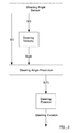
- the predicted future steering angle S(T) at time T is compared against a first threshold ⁇ , where ⁇ is the steering angle (either clockwise or anti-clockwise) from the straight ahead position (i.e. the angle at which the steering wheel is set for the vehicle 1 to be driven in a straight line). If the predicted steering angle is greater than this threshold (i.e. S(T) > ⁇ ), which may be adjusted based on the speed of the vehicle (as discussed in more detail below), then the system determines that the driver is steering to avoid a collision (for instance, by steering round a further vehicle in the course of overtaking the further vehicle), and a signal is generated which causes the active braking system of the vehicle to be suppressed.
- ⁇ is the steering angle (either clockwise or anti-clockwise) from the straight ahead position (i.e. the angle at which the steering wheel is set for the vehicle 1 to be driven in a straight line).
- the system determines that the driver is not performing a steering action to avoid a collision, and the active braking system operates as normal (i.e. the signal is not generated). This is shown schematically in figure 5 .
- the threshold ⁇ is fixed, and the threshold may for instance be exactly or approximately 100 degrees.
- the threshold ⁇ is dependent upon the speed of the vehicle. Firstly, for a given steering angle the vehicle will turn less at high speeds as a result of tyre slip. Secondly, it is more common to turn the steering wheel through a large angle at low speed, for instance during a turning or parking manoeuvre. However, despite this, it will still be desirable to suppress the active braking at low speeds if it appears that the driver is performing a steering action that will successfully avoid an obstacle. Overall, in preferred embodiments the threshold angle ⁇ is lower at lower speeds.
- the threshold angle ⁇ may be 90° when the vehicle is travelling at 30kph, 100° when the vehicle is travelling at 60kph, and 110° when the vehicle is travelling at 90kph.
- the skilled reader will understand how the threshold angle ⁇ may be extrapolated/interpolated for other speeds.
- the threshold angle ⁇ varies in a linear manner with speed, although it should be understood that this need not be the case and the threshold angle ⁇ may, for example, be proportional to the square of the velocity.
- the slip angle of one or more of the vehicle's wheels may be determined or approximated.
- the slip angle is a measure of the difference between the direction in which a wheel is pointing and the direction in which it is actually travelling, and is indicative of the coefficient of friction between the vehicle's tyres and the road surface.
- the threshold ⁇ may (in addition to, or as an alternative to, being dependent upon vehicle speed) depend on external driving conditions, such as the condition of the road surface, the presence of water or ice on the road, or the ambient temperature. If the driving conditions are good (e.g. the ambient temperature is well above freezing, and the vehicle is being driven along a dry road which is in a good condition), then the threshold ⁇ may be set to be relatively low, since the vehicle will react well to a steering action performed by the driver. However, if the driving conditions are such that the vehicle is more likely to lose traction during a turn (e.g.
- the threshold ⁇ may be set to be higher, since the vehicle's tyres will slip on the road and hence a greater steering angle will be needed to produce the same vehicle yaw rate.
- Information from one or more camera arrangements may be used to gain information about the driving conditions. Information may also be gained from one or more thermometers or rain sensors of the vehicle, and/or from weather/road surface information that is communicated to the vehicle from a remote control centre or other service. The skilled reader will realise how this may be achieved.
- the threshold ⁇ can be set to a relatively high level, compared to a system which only applies a threshold to the current position of the steering wheel.
- the steering angle at that moment is quite low, and is not significantly different from the steering angle that would be encountered if the driver was simply not paying attention and on a course to collide with the further vehicle 5.
- a system which analyses the current steering angle must therefore apply a low threshold, in order to distinguish between the two situations.
- the future steering angle that can be determined by the processor is significantly different from the future angle that will be determined if the driver is not commencing an overtaking manoeuvre and is on a course to collide with the further vehicle 5. Therefore, in embodiments of the invention a higher (and hence safer) threshold can be applied to the future steering angle to distinguish between the two situations.
- embodiments of the invention will also be more robust than a system which relies on steering rate alone, since the initial steering angle is taken into account, and so the system will not suppress the active braking system only in response to the steering wheel being turned relatively quickly, where this will not (within the time over which the prediction takes place) lead to a sharp angle of steering.
- the decision to suppress the automatic braking should be performed based on steering angle and steering velocity used in combination.
- the steering angle sensor is used to determine a starting angle, which is the angle S(0) at which the steering wheel is set at the present time, the rate S vel at which the steering wheel is being turned, and also the rate of acceleration S acc of the turning of the steering wheel.
- a starting angle which is the angle S(0) at which the steering wheel is set at the present time
- the rate S vel at which the steering wheel is being turned and also the rate of acceleration S acc of the turning of the steering wheel.
- this embodiment it is assumed that the driver will turn the steering wheel and continue to maintain the current rate of acceleration. Because this prediction uses position and both acceleration and velocity, it will generally produce a higher result than a prediction based only on position and velocity.
- This predicted steering angle is compared against a further threshold ⁇ . Once again, if the predicted steering angle is greater than this threshold (i.e. S(T) > ⁇ ) then the system determines that the driver is steering to avoid a collision (for instance, by steering round a further vehicle in the course of overtaking the further vehicle), and the active braking system of the vehicle is suppressed. If, on the other hand, the predicted steering angle is less than or equal to this threshold (i.e. S ( T ) ⁇ ⁇ ) then the system determines that the driver is not performing a steering action to avoid a collision, and the active braking system operates as normal. This is shown schematically in figure 6 .
- the further threshold ⁇ is greater than the threshold ⁇ . This is because, if the rate of acceleration of turning of the steering wheel is taken into account, a more accurate prediction of larger future steering angles can be made. For the reasons discussed above, this higher threshold allows a more robust and reliable determination to be made as to whether the active braking system should be suppressed.
- the further threshold ⁇ may be fixed, in which case the further threshold ⁇ may be set at exactly or around 110°.
- the further threshold ⁇ may vary in dependence upon the vehicle's speed.
- the further threshold ⁇ may be 100° when the vehicle is travelling at 30kph, 110° when the vehicle is travelling at 60kph, and 120° when the vehicle is travelling at 90kph.
- the skilled reader will again understand how the further threshold angle ⁇ may be extrapolated/interpolated for other speeds.
- the further threshold angle ⁇ may again vary in a linear manner with speed, although it should be understood that this need not be the case and the further threshold angle ⁇ may, for example, be proportional to the square of the velocity.
- the threshold may also vary depending on the surrounding driving conditions and/or the current detected slip angle.
- an active steering system may be suppressed or deactivated if it is determined (in the same way as discussed above) that the driver is performing an evasion or overtaking manoeuvre.
- the skilled reader will be aware of the operation of active steering systems, and how they may be suppressed or deactivated in a system of this kind.
- the distance to a further vehicle ahead of the vehicle is determined, for instance using an on-board radar system, and the speed of the vehicle is regulated to maintain a target distance between the vehicle and the further vehicle (sometimes known as "radar lock").
- this target distance may vary depending on the speed of the vehicles (safe distances between vehicles are sometimes based on the difference in time between the two vehicles passing the same stationary point, and so as the vehicles travel faster the safe distance between the vehicles increases).
- the radar lock of the cruise control system is deactivated, as it is determined that the driver of the vehicle may wish to perform an overtaking manoeuvre, and so the radar lock is no longer appropriate.
- the threshold against which the predicted future steering angle is compared for these purposes may be the same as any of those described above.
- the threshold may be lower, as it likely that the steering performed at the distance behind a further vehicle that is set by a cruise control system will be less sharp than that performed later on in an overtaking manoeuvre.
- the switching off of a radar lock is less serious, with regard to vehicle occupant safety, than the suppression of an active braking system, and so a lesser degree of certainty is likely to be acceptable.
- the present invention provides a robust and reliable system for determining when certain vehicle systems should be activated, suppressed or disengaged.
Landscapes
- Engineering & Computer Science (AREA)
- Transportation (AREA)
- Mechanical Engineering (AREA)
- Steering Control In Accordance With Driving Conditions (AREA)
- Control Of Driving Devices And Active Controlling Of Vehicle (AREA)
- Traffic Control Systems (AREA)
- Regulating Braking Force (AREA)
Priority Applications (1)
| Application Number | Priority Date | Filing Date | Title |
|---|---|---|---|
| EP14193418.2A EP3020609B1 (de) | 2014-11-17 | 2014-11-17 | Fahrzeugsicherheitssystem |
Applications Claiming Priority (1)
| Application Number | Priority Date | Filing Date | Title |
|---|---|---|---|
| EP14193418.2A EP3020609B1 (de) | 2014-11-17 | 2014-11-17 | Fahrzeugsicherheitssystem |
Publications (2)
| Publication Number | Publication Date |
|---|---|
| EP3020609A1 true EP3020609A1 (de) | 2016-05-18 |
| EP3020609B1 EP3020609B1 (de) | 2020-04-08 |
Family
ID=51900787
Family Applications (1)
| Application Number | Title | Priority Date | Filing Date |
|---|---|---|---|
| EP14193418.2A Active EP3020609B1 (de) | 2014-11-17 | 2014-11-17 | Fahrzeugsicherheitssystem |
Country Status (1)
| Country | Link |
|---|---|
| EP (1) | EP3020609B1 (de) |
Cited By (1)
| Publication number | Priority date | Publication date | Assignee | Title |
|---|---|---|---|---|
| CN109131274A (zh) * | 2018-08-30 | 2019-01-04 | 芜湖职业技术学院 | 大型车辆自动感应刹车装置 |
Families Citing this family (1)
| Publication number | Priority date | Publication date | Assignee | Title |
|---|---|---|---|---|
| CN111169462B (zh) * | 2019-12-27 | 2022-03-29 | 联创汽车电子有限公司 | 安全距离计算模块及其计算方法 |
Citations (5)
| Publication number | Priority date | Publication date | Assignee | Title |
|---|---|---|---|---|
| DE102007027644A1 (de) * | 2006-06-16 | 2007-12-27 | Nissan Motor Co., Ltd., Yokohama | Fahrzeug-Brems-Regelsystem |
| EP1995705A1 (de) * | 2006-03-06 | 2008-11-26 | Hitachi, Ltd. | Steuereinrichtung und verfahren für automobile |
| EP1997704A2 (de) * | 2007-05-28 | 2008-12-03 | HONDA MOTOR CO., Ltd. | Fahrzeugbetriebsunterstützungssystem |
| EP2051886A1 (de) | 2006-08-15 | 2009-04-29 | Toyota Jidosha Kabushiki Kaisha | Bremssteuerungssystem und bremssteuerungsverfahren |
| DE102008002171A1 (de) * | 2008-06-03 | 2009-12-10 | Robert Bosch Gmbh | Verfahren zur Vorhersage der zukünftigen Bewegung einer Steuereinrichtung in einem Fahrzeug |
-
2014
- 2014-11-17 EP EP14193418.2A patent/EP3020609B1/de active Active
Patent Citations (5)
| Publication number | Priority date | Publication date | Assignee | Title |
|---|---|---|---|---|
| EP1995705A1 (de) * | 2006-03-06 | 2008-11-26 | Hitachi, Ltd. | Steuereinrichtung und verfahren für automobile |
| DE102007027644A1 (de) * | 2006-06-16 | 2007-12-27 | Nissan Motor Co., Ltd., Yokohama | Fahrzeug-Brems-Regelsystem |
| EP2051886A1 (de) | 2006-08-15 | 2009-04-29 | Toyota Jidosha Kabushiki Kaisha | Bremssteuerungssystem und bremssteuerungsverfahren |
| EP1997704A2 (de) * | 2007-05-28 | 2008-12-03 | HONDA MOTOR CO., Ltd. | Fahrzeugbetriebsunterstützungssystem |
| DE102008002171A1 (de) * | 2008-06-03 | 2009-12-10 | Robert Bosch Gmbh | Verfahren zur Vorhersage der zukünftigen Bewegung einer Steuereinrichtung in einem Fahrzeug |
Cited By (1)
| Publication number | Priority date | Publication date | Assignee | Title |
|---|---|---|---|---|
| CN109131274A (zh) * | 2018-08-30 | 2019-01-04 | 芜湖职业技术学院 | 大型车辆自动感应刹车装置 |
Also Published As
| Publication number | Publication date |
|---|---|
| EP3020609B1 (de) | 2020-04-08 |
Similar Documents
| Publication | Publication Date | Title |
|---|---|---|
| KR102206689B1 (ko) | 추월지원시스템을 위한 방법 및 장치 | |
| US8762043B2 (en) | Method and system for collision course prediction and collision avoidance and mitigation | |
| EP2837538B1 (de) | Fahrzeugsicherheitssystem | |
| EP3078515B1 (de) | Kollisionsvermeidung auf basis von vorderradausschaltverfolgung im rückwärtsbetrieb | |
| US10272910B2 (en) | Driver assistance system and methods for collision avoidance | |
| JP6589760B2 (ja) | 車両制御装置 | |
| EP3018026B1 (de) | Verfahren zur Vorhersage eines Fahrzeugpfads | |
| EP3221856B1 (de) | Auf sich extrem schnell annähernde fahrzeuge reagierendes fahrspurassistenzsystem | |
| US9852633B2 (en) | Travel assist apparatus and travel assist method | |
| EP1857991B1 (de) | Gerät zum feststellen ob ein fahrzeug die spur verlässt | |
| US9771055B1 (en) | Front impact mitigation system for a vehicle and method | |
| US20130274959A1 (en) | Driving support apparatus, driving support method, and vehicle | |
| CN106985780A (zh) | 车辆安全辅助系统 | |
| CN110745134B (zh) | 用于向主车辆的驾驶员提供转向引导的方法和系统 | |
| EP3705384B1 (de) | Seitenkollisionsrisikoschätzungssystem für ein fahrzeug | |
| CN111845770A (zh) | 用于识别车辆的拖挂车的系统及其方法 | |
| US10787171B2 (en) | Method for operating a vehicle | |
| CN107139921A (zh) | 一种用于车辆的转向防碰撞方法及系统 | |
| CN107021097B (zh) | 车辆可见性增强系统,包括该系统的车辆和增强车辆可见性的方法 | |
| KR102459493B1 (ko) | 지능형 협업 제동 시스템 및 방법 | |
| KR102520242B1 (ko) | 차선 유지 제어 시스템 및 그에 의한 조향 제어 방법 | |
| EP3020609B1 (de) | Fahrzeugsicherheitssystem | |
| KR102007359B1 (ko) | 고속도로 주행 지원 시스템 연동 자동 긴급 제동 시스템 및 방법 | |
| EP4194297B1 (de) | Kollisionsanzeige auf der basis von gierraten- und seitengeschwindigkeitsschwellen | |
| JP2008114731A (ja) | 目標物監視装置、及び目標物監視方法 |
Legal Events
| Date | Code | Title | Description |
|---|---|---|---|
| PUAI | Public reference made under article 153(3) epc to a published international application that has entered the european phase |
Free format text: ORIGINAL CODE: 0009012 |
|
| AK | Designated contracting states |
Kind code of ref document: A1 Designated state(s): AL AT BE BG CH CY CZ DE DK EE ES FI FR GB GR HR HU IE IS IT LI LT LU LV MC MK MT NL NO PL PT RO RS SE SI SK SM TR |
|
| AX | Request for extension of the european patent |
Extension state: BA ME |
|
| STAA | Information on the status of an ep patent application or granted ep patent |
Free format text: STATUS: REQUEST FOR EXAMINATION WAS MADE |
|
| 17P | Request for examination filed |
Effective date: 20161102 |
|
| RBV | Designated contracting states (corrected) |
Designated state(s): AL AT BE BG CH CY CZ DE DK EE ES FI FR GB GR HR HU IE IS IT LI LT LU LV MC MK MT NL NO PL PT RO RS SE SI SK SM TR |
|
| STAA | Information on the status of an ep patent application or granted ep patent |
Free format text: STATUS: EXAMINATION IS IN PROGRESS |
|
| 17Q | First examination report despatched |
Effective date: 20190125 |
|
| RAP1 | Party data changed (applicant data changed or rights of an application transferred) |
Owner name: VEONEER SWEDEN AB |
|
| GRAP | Despatch of communication of intention to grant a patent |
Free format text: ORIGINAL CODE: EPIDOSNIGR1 |
|
| STAA | Information on the status of an ep patent application or granted ep patent |
Free format text: STATUS: GRANT OF PATENT IS INTENDED |
|
| INTG | Intention to grant announced |
Effective date: 20191030 |
|
| GRAS | Grant fee paid |
Free format text: ORIGINAL CODE: EPIDOSNIGR3 |
|
| GRAA | (expected) grant |
Free format text: ORIGINAL CODE: 0009210 |
|
| STAA | Information on the status of an ep patent application or granted ep patent |
Free format text: STATUS: THE PATENT HAS BEEN GRANTED |
|
| AK | Designated contracting states |
Kind code of ref document: B1 Designated state(s): AL AT BE BG CH CY CZ DE DK EE ES FI FR GB GR HR HU IE IS IT LI LT LU LV MC MK MT NL NO PL PT RO RS SE SI SK SM TR |
|
| REG | Reference to a national code |
Ref country code: CH Ref legal event code: EP Ref country code: AT Ref legal event code: REF Ref document number: 1253974 Country of ref document: AT Kind code of ref document: T Effective date: 20200415 |
|
| REG | Reference to a national code |
Ref country code: IE Ref legal event code: FG4D |
|
| REG | Reference to a national code |
Ref country code: DE Ref legal event code: R096 Ref document number: 602014063430 Country of ref document: DE |
|
| REG | Reference to a national code |
Ref country code: SE Ref legal event code: TRGR |
|
| REG | Reference to a national code |
Ref country code: NL Ref legal event code: MP Effective date: 20200408 |
|
| REG | Reference to a national code |
Ref country code: LT Ref legal event code: MG4D |
|
| PG25 | Lapsed in a contracting state [announced via postgrant information from national office to epo] |
Ref country code: FI Free format text: LAPSE BECAUSE OF FAILURE TO SUBMIT A TRANSLATION OF THE DESCRIPTION OR TO PAY THE FEE WITHIN THE PRESCRIBED TIME-LIMIT Effective date: 20200408 Ref country code: PT Free format text: LAPSE BECAUSE OF FAILURE TO SUBMIT A TRANSLATION OF THE DESCRIPTION OR TO PAY THE FEE WITHIN THE PRESCRIBED TIME-LIMIT Effective date: 20200817 Ref country code: GR Free format text: LAPSE BECAUSE OF FAILURE TO SUBMIT A TRANSLATION OF THE DESCRIPTION OR TO PAY THE FEE WITHIN THE PRESCRIBED TIME-LIMIT Effective date: 20200709 Ref country code: NO Free format text: LAPSE BECAUSE OF FAILURE TO SUBMIT A TRANSLATION OF THE DESCRIPTION OR TO PAY THE FEE WITHIN THE PRESCRIBED TIME-LIMIT Effective date: 20200708 Ref country code: IS Free format text: LAPSE BECAUSE OF FAILURE TO SUBMIT A TRANSLATION OF THE DESCRIPTION OR TO PAY THE FEE WITHIN THE PRESCRIBED TIME-LIMIT Effective date: 20200808 Ref country code: LT Free format text: LAPSE BECAUSE OF FAILURE TO SUBMIT A TRANSLATION OF THE DESCRIPTION OR TO PAY THE FEE WITHIN THE PRESCRIBED TIME-LIMIT Effective date: 20200408 Ref country code: NL Free format text: LAPSE BECAUSE OF FAILURE TO SUBMIT A TRANSLATION OF THE DESCRIPTION OR TO PAY THE FEE WITHIN THE PRESCRIBED TIME-LIMIT Effective date: 20200408 |
|
| REG | Reference to a national code |
Ref country code: AT Ref legal event code: MK05 Ref document number: 1253974 Country of ref document: AT Kind code of ref document: T Effective date: 20200408 |
|
| PG25 | Lapsed in a contracting state [announced via postgrant information from national office to epo] |
Ref country code: HR Free format text: LAPSE BECAUSE OF FAILURE TO SUBMIT A TRANSLATION OF THE DESCRIPTION OR TO PAY THE FEE WITHIN THE PRESCRIBED TIME-LIMIT Effective date: 20200408 Ref country code: LV Free format text: LAPSE BECAUSE OF FAILURE TO SUBMIT A TRANSLATION OF THE DESCRIPTION OR TO PAY THE FEE WITHIN THE PRESCRIBED TIME-LIMIT Effective date: 20200408 Ref country code: BG Free format text: LAPSE BECAUSE OF FAILURE TO SUBMIT A TRANSLATION OF THE DESCRIPTION OR TO PAY THE FEE WITHIN THE PRESCRIBED TIME-LIMIT Effective date: 20200708 Ref country code: RS Free format text: LAPSE BECAUSE OF FAILURE TO SUBMIT A TRANSLATION OF THE DESCRIPTION OR TO PAY THE FEE WITHIN THE PRESCRIBED TIME-LIMIT Effective date: 20200408 |
|
| PG25 | Lapsed in a contracting state [announced via postgrant information from national office to epo] |
Ref country code: AL Free format text: LAPSE BECAUSE OF FAILURE TO SUBMIT A TRANSLATION OF THE DESCRIPTION OR TO PAY THE FEE WITHIN THE PRESCRIBED TIME-LIMIT Effective date: 20200408 |
|
| REG | Reference to a national code |
Ref country code: DE Ref legal event code: R097 Ref document number: 602014063430 Country of ref document: DE |
|
| PG25 | Lapsed in a contracting state [announced via postgrant information from national office to epo] |
Ref country code: AT Free format text: LAPSE BECAUSE OF FAILURE TO SUBMIT A TRANSLATION OF THE DESCRIPTION OR TO PAY THE FEE WITHIN THE PRESCRIBED TIME-LIMIT Effective date: 20200408 Ref country code: ES Free format text: LAPSE BECAUSE OF FAILURE TO SUBMIT A TRANSLATION OF THE DESCRIPTION OR TO PAY THE FEE WITHIN THE PRESCRIBED TIME-LIMIT Effective date: 20200408 Ref country code: IT Free format text: LAPSE BECAUSE OF FAILURE TO SUBMIT A TRANSLATION OF THE DESCRIPTION OR TO PAY THE FEE WITHIN THE PRESCRIBED TIME-LIMIT Effective date: 20200408 Ref country code: CZ Free format text: LAPSE BECAUSE OF FAILURE TO SUBMIT A TRANSLATION OF THE DESCRIPTION OR TO PAY THE FEE WITHIN THE PRESCRIBED TIME-LIMIT Effective date: 20200408 Ref country code: RO Free format text: LAPSE BECAUSE OF FAILURE TO SUBMIT A TRANSLATION OF THE DESCRIPTION OR TO PAY THE FEE WITHIN THE PRESCRIBED TIME-LIMIT Effective date: 20200408 Ref country code: EE Free format text: LAPSE BECAUSE OF FAILURE TO SUBMIT A TRANSLATION OF THE DESCRIPTION OR TO PAY THE FEE WITHIN THE PRESCRIBED TIME-LIMIT Effective date: 20200408 Ref country code: SM Free format text: LAPSE BECAUSE OF FAILURE TO SUBMIT A TRANSLATION OF THE DESCRIPTION OR TO PAY THE FEE WITHIN THE PRESCRIBED TIME-LIMIT Effective date: 20200408 Ref country code: DK Free format text: LAPSE BECAUSE OF FAILURE TO SUBMIT A TRANSLATION OF THE DESCRIPTION OR TO PAY THE FEE WITHIN THE PRESCRIBED TIME-LIMIT Effective date: 20200408 |
|
| PGFP | Annual fee paid to national office [announced via postgrant information from national office to epo] |
Ref country code: FR Payment date: 20201127 Year of fee payment: 7 Ref country code: SE Payment date: 20201123 Year of fee payment: 7 Ref country code: GB Payment date: 20201126 Year of fee payment: 7 |
|
| PLBE | No opposition filed within time limit |
Free format text: ORIGINAL CODE: 0009261 |
|
| STAA | Information on the status of an ep patent application or granted ep patent |
Free format text: STATUS: NO OPPOSITION FILED WITHIN TIME LIMIT |
|
| PG25 | Lapsed in a contracting state [announced via postgrant information from national office to epo] |
Ref country code: SK Free format text: LAPSE BECAUSE OF FAILURE TO SUBMIT A TRANSLATION OF THE DESCRIPTION OR TO PAY THE FEE WITHIN THE PRESCRIBED TIME-LIMIT Effective date: 20200408 Ref country code: PL Free format text: LAPSE BECAUSE OF FAILURE TO SUBMIT A TRANSLATION OF THE DESCRIPTION OR TO PAY THE FEE WITHIN THE PRESCRIBED TIME-LIMIT Effective date: 20200408 |
|
| 26N | No opposition filed |
Effective date: 20210112 |
|
| PG25 | Lapsed in a contracting state [announced via postgrant information from national office to epo] |
Ref country code: SI Free format text: LAPSE BECAUSE OF FAILURE TO SUBMIT A TRANSLATION OF THE DESCRIPTION OR TO PAY THE FEE WITHIN THE PRESCRIBED TIME-LIMIT Effective date: 20200408 |
|
| PG25 | Lapsed in a contracting state [announced via postgrant information from national office to epo] |
Ref country code: MC Free format text: LAPSE BECAUSE OF FAILURE TO SUBMIT A TRANSLATION OF THE DESCRIPTION OR TO PAY THE FEE WITHIN THE PRESCRIBED TIME-LIMIT Effective date: 20200408 |
|
| REG | Reference to a national code |
Ref country code: CH Ref legal event code: PL |
|
| PG25 | Lapsed in a contracting state [announced via postgrant information from national office to epo] |
Ref country code: LU Free format text: LAPSE BECAUSE OF NON-PAYMENT OF DUE FEES Effective date: 20201117 |
|
| REG | Reference to a national code |
Ref country code: BE Ref legal event code: MM Effective date: 20201130 |
|
| PG25 | Lapsed in a contracting state [announced via postgrant information from national office to epo] |
Ref country code: CH Free format text: LAPSE BECAUSE OF NON-PAYMENT OF DUE FEES Effective date: 20201130 Ref country code: LI Free format text: LAPSE BECAUSE OF NON-PAYMENT OF DUE FEES Effective date: 20201130 |
|
| PG25 | Lapsed in a contracting state [announced via postgrant information from national office to epo] |
Ref country code: IE Free format text: LAPSE BECAUSE OF NON-PAYMENT OF DUE FEES Effective date: 20201117 |
|
| PG25 | Lapsed in a contracting state [announced via postgrant information from national office to epo] |
Ref country code: TR Free format text: LAPSE BECAUSE OF FAILURE TO SUBMIT A TRANSLATION OF THE DESCRIPTION OR TO PAY THE FEE WITHIN THE PRESCRIBED TIME-LIMIT Effective date: 20200408 Ref country code: MT Free format text: LAPSE BECAUSE OF FAILURE TO SUBMIT A TRANSLATION OF THE DESCRIPTION OR TO PAY THE FEE WITHIN THE PRESCRIBED TIME-LIMIT Effective date: 20200408 Ref country code: CY Free format text: LAPSE BECAUSE OF FAILURE TO SUBMIT A TRANSLATION OF THE DESCRIPTION OR TO PAY THE FEE WITHIN THE PRESCRIBED TIME-LIMIT Effective date: 20200408 |
|
| PG25 | Lapsed in a contracting state [announced via postgrant information from national office to epo] |
Ref country code: MK Free format text: LAPSE BECAUSE OF FAILURE TO SUBMIT A TRANSLATION OF THE DESCRIPTION OR TO PAY THE FEE WITHIN THE PRESCRIBED TIME-LIMIT Effective date: 20200408 |
|
| GBPC | Gb: european patent ceased through non-payment of renewal fee |
Effective date: 20211117 |
|
| PG25 | Lapsed in a contracting state [announced via postgrant information from national office to epo] |
Ref country code: SE Free format text: LAPSE BECAUSE OF NON-PAYMENT OF DUE FEES Effective date: 20211118 Ref country code: BE Free format text: LAPSE BECAUSE OF NON-PAYMENT OF DUE FEES Effective date: 20201130 |
|
| REG | Reference to a national code |
Ref country code: DE Ref legal event code: R082 Ref document number: 602014063430 Country of ref document: DE Representative=s name: BARDEHLE PAGENBERG PARTNERSCHAFT MBB PATENTANW, DE |
|
| REG | Reference to a national code |
Ref country code: DE Ref legal event code: R081 Ref document number: 602014063430 Country of ref document: DE Owner name: ARRIVER SOFTWARE AB, SE Free format text: FORMER OWNER: VEONEER SWEDEN AB, VARGARDA, SE Ref country code: DE Ref legal event code: R081 Ref document number: 602014063430 Country of ref document: DE Owner name: QUALCOMM AUTO LTD., GB Free format text: FORMER OWNER: VEONEER SWEDEN AB, VARGARDA, SE |
|
| PG25 | Lapsed in a contracting state [announced via postgrant information from national office to epo] |
Ref country code: GB Free format text: LAPSE BECAUSE OF NON-PAYMENT OF DUE FEES Effective date: 20211117 |
|
| PG25 | Lapsed in a contracting state [announced via postgrant information from national office to epo] |
Ref country code: FR Free format text: LAPSE BECAUSE OF NON-PAYMENT OF DUE FEES Effective date: 20211130 |
|
| PGFP | Annual fee paid to national office [announced via postgrant information from national office to epo] |
Ref country code: DE Payment date: 20241010 Year of fee payment: 11 |
|
| REG | Reference to a national code |
Ref country code: DE Ref legal event code: R081 Ref document number: 602014063430 Country of ref document: DE Owner name: QUALCOMM AUTO LTD., GB Free format text: FORMER OWNER: ARRIVER SOFTWARE AB, LINKOEPING, SE |