EP3020636A1 - Tirant auto-amortissant - Google Patents
Tirant auto-amortissant Download PDFInfo
- Publication number
- EP3020636A1 EP3020636A1 EP15192542.7A EP15192542A EP3020636A1 EP 3020636 A1 EP3020636 A1 EP 3020636A1 EP 15192542 A EP15192542 A EP 15192542A EP 3020636 A1 EP3020636 A1 EP 3020636A1
- Authority
- EP
- European Patent Office
- Prior art keywords
- enclosure
- opening
- sidewall
- tie rod
- rod assembly
- Prior art date
- Legal status (The legal status is an assumption and is not a legal conclusion. Google has not performed a legal analysis and makes no representation as to the accuracy of the status listed.)
- Granted
Links
Images


Classifications
-
- B—PERFORMING OPERATIONS; TRANSPORTING
- B64—AIRCRAFT; AVIATION; COSMONAUTICS
- B64D—EQUIPMENT FOR FITTING IN OR TO AIRCRAFT; FLIGHT SUITS; PARACHUTES; ARRANGEMENT OR MOUNTING OF POWER PLANTS OR PROPULSION TRANSMISSIONS IN AIRCRAFT
- B64D11/00—Passenger or crew accommodation; Flight-deck installations not otherwise provided for
-
- F—MECHANICAL ENGINEERING; LIGHTING; HEATING; WEAPONS; BLASTING
- F16—ENGINEERING ELEMENTS AND UNITS; GENERAL MEASURES FOR PRODUCING AND MAINTAINING EFFECTIVE FUNCTIONING OF MACHINES OR INSTALLATIONS; THERMAL INSULATION IN GENERAL
- F16F—SPRINGS; SHOCK-ABSORBERS; MEANS FOR DAMPING VIBRATION
- F16F13/00—Units comprising springs of the non-fluid type as well as vibration-dampers, shock-absorbers, or fluid springs
- F16F13/005—Units comprising springs of the non-fluid type as well as vibration-dampers, shock-absorbers, or fluid springs comprising both a wound spring and a damper, e.g. a friction damper
- F16F13/007—Units comprising springs of the non-fluid type as well as vibration-dampers, shock-absorbers, or fluid springs comprising both a wound spring and a damper, e.g. a friction damper the damper being a fluid damper
-
- F—MECHANICAL ENGINEERING; LIGHTING; HEATING; WEAPONS; BLASTING
- F16—ENGINEERING ELEMENTS AND UNITS; GENERAL MEASURES FOR PRODUCING AND MAINTAINING EFFECTIVE FUNCTIONING OF MACHINES OR INSTALLATIONS; THERMAL INSULATION IN GENERAL
- F16F—SPRINGS; SHOCK-ABSORBERS; MEANS FOR DAMPING VIBRATION
- F16F9/00—Springs, vibration-dampers, shock-absorbers, or similarly-constructed movement-dampers using a fluid or the equivalent as damping medium
- F16F9/06—Springs, vibration-dampers, shock-absorbers, or similarly-constructed movement-dampers using a fluid or the equivalent as damping medium using both gas and liquid
- F16F9/062—Bi-tubular units
-
- F—MECHANICAL ENGINEERING; LIGHTING; HEATING; WEAPONS; BLASTING
- F16—ENGINEERING ELEMENTS AND UNITS; GENERAL MEASURES FOR PRODUCING AND MAINTAINING EFFECTIVE FUNCTIONING OF MACHINES OR INSTALLATIONS; THERMAL INSULATION IN GENERAL
- F16F—SPRINGS; SHOCK-ABSORBERS; MEANS FOR DAMPING VIBRATION
- F16F9/00—Springs, vibration-dampers, shock-absorbers, or similarly-constructed movement-dampers using a fluid or the equivalent as damping medium
- F16F9/10—Springs, vibration-dampers, shock-absorbers, or similarly-constructed movement-dampers using a fluid or the equivalent as damping medium using liquid only; using a fluid of which the nature is immaterial
- F16F9/14—Devices with one or more members, e.g. pistons, vanes, moving to and fro in chambers and using throttling effect
- F16F9/16—Devices with one or more members, e.g. pistons, vanes, moving to and fro in chambers and using throttling effect involving only straight-line movement of the effective parts
- F16F9/18—Devices with one or more members, e.g. pistons, vanes, moving to and fro in chambers and using throttling effect involving only straight-line movement of the effective parts with a closed cylinder and a piston separating two or more working spaces therein
- F16F9/185—Bitubular units
-
- F—MECHANICAL ENGINEERING; LIGHTING; HEATING; WEAPONS; BLASTING
- F16—ENGINEERING ELEMENTS AND UNITS; GENERAL MEASURES FOR PRODUCING AND MAINTAINING EFFECTIVE FUNCTIONING OF MACHINES OR INSTALLATIONS; THERMAL INSULATION IN GENERAL
- F16F—SPRINGS; SHOCK-ABSORBERS; MEANS FOR DAMPING VIBRATION
- F16F9/00—Springs, vibration-dampers, shock-absorbers, or similarly-constructed movement-dampers using a fluid or the equivalent as damping medium
- F16F9/10—Springs, vibration-dampers, shock-absorbers, or similarly-constructed movement-dampers using a fluid or the equivalent as damping medium using liquid only; using a fluid of which the nature is immaterial
- F16F9/14—Devices with one or more members, e.g. pistons, vanes, moving to and fro in chambers and using throttling effect
- F16F9/16—Devices with one or more members, e.g. pistons, vanes, moving to and fro in chambers and using throttling effect involving only straight-line movement of the effective parts
- F16F9/18—Devices with one or more members, e.g. pistons, vanes, moving to and fro in chambers and using throttling effect involving only straight-line movement of the effective parts with a closed cylinder and a piston separating two or more working spaces therein
- F16F9/19—Devices with one or more members, e.g. pistons, vanes, moving to and fro in chambers and using throttling effect involving only straight-line movement of the effective parts with a closed cylinder and a piston separating two or more working spaces therein with a single cylinder and of single-tube type
-
- F—MECHANICAL ENGINEERING; LIGHTING; HEATING; WEAPONS; BLASTING
- F16—ENGINEERING ELEMENTS AND UNITS; GENERAL MEASURES FOR PRODUCING AND MAINTAINING EFFECTIVE FUNCTIONING OF MACHINES OR INSTALLATIONS; THERMAL INSULATION IN GENERAL
- F16F—SPRINGS; SHOCK-ABSORBERS; MEANS FOR DAMPING VIBRATION
- F16F9/00—Springs, vibration-dampers, shock-absorbers, or similarly-constructed movement-dampers using a fluid or the equivalent as damping medium
- F16F9/32—Details
- F16F9/3264—Arrangements for indicating, e.g. fluid level; Arrangements for checking dampers
-
- F—MECHANICAL ENGINEERING; LIGHTING; HEATING; WEAPONS; BLASTING
- F16—ENGINEERING ELEMENTS AND UNITS; GENERAL MEASURES FOR PRODUCING AND MAINTAINING EFFECTIVE FUNCTIONING OF MACHINES OR INSTALLATIONS; THERMAL INSULATION IN GENERAL
- F16F—SPRINGS; SHOCK-ABSORBERS; MEANS FOR DAMPING VIBRATION
- F16F9/00—Springs, vibration-dampers, shock-absorbers, or similarly-constructed movement-dampers using a fluid or the equivalent as damping medium
- F16F9/32—Details
- F16F9/34—Special valve constructions; Shape or construction of throttling passages
-
- F—MECHANICAL ENGINEERING; LIGHTING; HEATING; WEAPONS; BLASTING
- F16—ENGINEERING ELEMENTS AND UNITS; GENERAL MEASURES FOR PRODUCING AND MAINTAINING EFFECTIVE FUNCTIONING OF MACHINES OR INSTALLATIONS; THERMAL INSULATION IN GENERAL
- F16F—SPRINGS; SHOCK-ABSORBERS; MEANS FOR DAMPING VIBRATION
- F16F9/00—Springs, vibration-dampers, shock-absorbers, or similarly-constructed movement-dampers using a fluid or the equivalent as damping medium
- F16F9/32—Details
- F16F9/50—Special means providing automatic damping adjustment, i.e. self-adjustment of damping by particular sliding movements of a valve element, other than flexions or displacement of valve discs; Special means providing self-adjustment of spring characteristics
- F16F9/512—Means responsive to load action, i.e. static load on the damper or dynamic fluid pressure changes in the damper, e.g. due to changes in velocity
-
- F—MECHANICAL ENGINEERING; LIGHTING; HEATING; WEAPONS; BLASTING
- F16—ENGINEERING ELEMENTS AND UNITS; GENERAL MEASURES FOR PRODUCING AND MAINTAINING EFFECTIVE FUNCTIONING OF MACHINES OR INSTALLATIONS; THERMAL INSULATION IN GENERAL
- F16F—SPRINGS; SHOCK-ABSORBERS; MEANS FOR DAMPING VIBRATION
- F16F2230/00—Purpose; Design features
- F16F2230/0047—Measuring, indicating
-
- F—MECHANICAL ENGINEERING; LIGHTING; HEATING; WEAPONS; BLASTING
- F16—ENGINEERING ELEMENTS AND UNITS; GENERAL MEASURES FOR PRODUCING AND MAINTAINING EFFECTIVE FUNCTIONING OF MACHINES OR INSTALLATIONS; THERMAL INSULATION IN GENERAL
- F16F—SPRINGS; SHOCK-ABSORBERS; MEANS FOR DAMPING VIBRATION
- F16F2236/00—Mode of stressing of basic spring or damper elements or devices incorporating such elements
- F16F2236/12—Mode of stressing of basic spring or damper elements or devices incorporating such elements loaded in combined stresses
-
- F—MECHANICAL ENGINEERING; LIGHTING; HEATING; WEAPONS; BLASTING
- F16—ENGINEERING ELEMENTS AND UNITS; GENERAL MEASURES FOR PRODUCING AND MAINTAINING EFFECTIVE FUNCTIONING OF MACHINES OR INSTALLATIONS; THERMAL INSULATION IN GENERAL
- F16F—SPRINGS; SHOCK-ABSORBERS; MEANS FOR DAMPING VIBRATION
- F16F2238/00—Type of springs or dampers
- F16F2238/04—Damper
Definitions
- This invention relates to a tie rod connector, and more particularly, to a tie rod connector subjected to tensile and compression forces.
- Tie rods are used to secure cabin interior monuments within an aircraft.
- monuments that are secured within the cabin of the aircraft such as closets, bar units, lowered ceilings, partitions, seat ottomans and the like.
- Some monuments are affixed to the floor within the cabin and then also affixed to the structure of the aircraft with tie rods.
- tie rods With the flexibility of a fuselage, the fuselage of an in-flight aircraft will experience structural egging and crowning movements. These movements of the fuselage are transmitted as tensile and compression forces through the tie rods to the monument the tie rods secure.
- the tensile and compression forces that are received by the monument from the tie rod, during in-flight operations, will cause structural issues such as stress to joints and racking which can also result in functional issues for the monument.
- tie rods securing a closet within the cabin will transmit these tensile and compression forces to the closet and create stressed joints and move portions of the closet structure out of alignment. With the closet structure out of alignment, the doors to the closet will bind and will inhibit or prevent the doors from being opened.
- the assembly includes a first rod member.
- An enclosure defines an opening and contains a fluid with the first rod member affixed to the enclosure.
- a second rod member extends through the opening with a seal member positioned between the second rod member and the enclosure.
- the assembly further includes a head member affixed to the second rod member with the head member positioned within the enclosure and the head member and the second rod member are moveable relative to the enclosure.
- Tie rods have been used as connectors for connecting monuments positioned within a cabin of an aircraft to the aircraft structure.
- the aircraft structure flexes in-flight imparting movement which results in the tie rods transmitting loads onto the monument the tie rod supports.
- the forces imparted onto the monument such as a closet, create stressing of joints and impart misalignment and racking of the structure inhibiting or preventing the opening of the door of the monument in-flight.
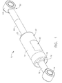
- tie rod assembly embodiments 10 and 100 as shown in FIGS. 1-4 and FIGS. 5-10 , respectively, will prevent the operational loading onto the monument the tie rod assembly supports and will perform as a rigid connection in severe loading events.
- tie rod assembly 10 has a first rod member 12 and has a fitting 14 affixed to first rod member 12.
- First fitting 14 is used for connecting tie rod assembly to one of a monument or to a structure of the aircraft.
- First fitting 14 can be selected from a variety of connection fittings such as forked, clevis, or a threaded end or the like so as to appropriately attach first rod member 12.
- First rod member 12 is affixed to enclosure 18 at opposing end16 of first rod member 12.
- Enclosure 18, in this example, is a sealed container that is substantially filled with a fluid such as oil, hydraulic fluid, silicone fluid, or the like, which has a viscosity within the range of ten centipoise (10cP) to one thousand centipoise (1000cP).
- Enclosure 18, in this example is generally cylindrical in shape and is closed at opposing ends, first end 19 and second end 21, of enclosure 18.
- Enclosure 18 also defines opening 20, as seen in FIGS. 3 and 4 , through which second rod member 22 extends. At least a portion of second rod member 22 is positioned within enclosure 18.
- Enclosure 18 is sealed such that the fluid contained within enclosure 18 is prevented from exiting enclosure 18 with use of O-ring or seal 24 positioned between second rod member 22 and enclosure 18 at opening 20.
- This O-ring or seal 24 or the like provides resistance from fluid leaking out of enclosure 18 with operational fluid pressures in the range of approximately one hundred pounds per square inch (100psi) and five thousand pounds per square inch (5000psi) being exerted onto seal 24.
- Seal or O-rings can be employed from a wide variety of seals and O-rings to provide the fluid pressure resistance necessary to resist the fluid pressure exerted within enclosure 18 for the particular tie rod assembly10 in operation.
- Head member 26 is positioned within enclosure 18 and is affixed to second rod member 22, as seen in FIGS. 2-4 .
- Second rod member 22 and head member 26 are moveable relative to enclosure 18, as will be discussed in more detail herein.
- Second rod member 22 has second fitting 28 affixed to end portion 30 of second rod member 22.
- Fitting 28 is used to connect tie rod assembly 10 to the other of the monument or the structure of the aircraft to which first fitting 14 is connected.
- second fitting 28 can be selected from a variety of connection fittings such as forked, clevis or a threaded end or the like so as to appropriately attach second rod member 22.
- Enclosure 18 can be constructed of a material selected from a variety of materials, such as metal or plastic.
- first rod member 12, second rod member 22 and head member 26 can also be constructed of a material selected from a variety of materials such as metal or plastic.
- the materials for tie rod assembly 10 are selected appropriately for the environment in which assembly 10 will used and the forces assembly 10 will engage.
- head member 26 separates interior 30 of enclosure 18 into a first volume 32 and second volume 34.
- Head member 26 has O-ring or seal 33 positioned between head member 26 and interior surface 35 of enclosure 18. With using O-ring or seal 33, head member 26 is allowed to move along interior surface 35.
- O-ring or seal 33 also provide a seal between interior surface 35 and head member 26 not permitting fluid contained within enclosure 18 to move between first volume 32 and second volume 34 by way of flowing between head member 26 and interior surface 35.
- O-ring or seal 33 can be selected from a variety of O-rings or seals, such as silicone, Teflon, Neoprene or rubber and the like.
- O-ring 33 will seal a pressure of fluid in the range of one hundred pounds per square inch (100psi) to five thousand pounds per square inch (5000psi).
- a seal or O-ring 33 can be selected from a variety of seals and O-rinks so as to provide the fluid pressure resistance necessary to resist the fluid pressure exerted within enclosure 18 onto O-rings or seal 33 for the particular tie rod assembly10 in operation.
- Opening 36 is defined by head member 26 and extends through head member 26 placing the first volume 32 in fluid communication with second volume 34.
- a plurality of openings 36 are positioned spaced apart from one another.
- openings 36 are positioned with adjacent openings 36 being spaced apart the same distance and are positioned about a longitudinal axis 38 of second rod member 22.
- This balanced distribution of openings 36 within head member 26 will provide even distribution of flow of fluid within enclosure 18 flowing from first volume 32 to second volume 34 and in the reverse direction from second volume 34 to first volume 32.
- An imbalance of flow of fluid between first and second volumes 32 and 34 would exert a torque onto head member 26 which would otherwise tend to cause head member 26 to bind against interior surface 35 within enclosure 18.
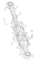
- tie rod assembly 10 has fittings 14 and 28, in this example, secured to a top of a closet and to an upper structure of the fuselage, respectively.
- In-flight operation has the structure of the aircraft fuselage experiencing structural egging and crowning movements. This movement will be transferred to tie rod assembly 10 through fitting 28, to second rod member 22 and to head member 26 within enclosure 18.
- a force received by head member 26 of tie rod assembly 10 through in-flight operations such as two pounds (2 lbs) is known.
- a fluid for enclosure 18 is selected with a known viscosity, such as six hundred and thirty centipoise (630cP), in this example.
- the minimum radius of openings 36 of head member is calculated to permit the fluid to pass through openings 36 between first and second volumes 32 and 34 with forces such as two pounds (2 lbs) from normal in-flight operations exerted onto tie rod assembly 10.
- normal flight operations may include one inch (1 inch) of travel within one second (1 second) of time to be a design criteria for tie rod assembly 10 to permit head member 26 to move through the fluid within enclosure 18 and not transmit forces to first rod member 12 and onto the monument tie rod assembly 10 secures.
- the calculations for the minimum radius for openings 36 to allow head member head 26 to move through the fluid within enclosure 18 is as follows:
- head member 26 With a minimum radius of 0.01 inches, for this example, head member 26 will move through the fluid within enclosure 18 during in-flight operations and not transmit forces through first fitting 114 to the monument. However, with an extraordinary large force, outside of normal in-flight operational loadings, being exerted through second rod member 22, head member 26 will not be able to move within enclosure 18. Head member 26 will be arrested from movement, in this example, with a force applied to head member 26 through second rod member 22 of nine g (9g) within 0.04 seconds of time. Head member 26 will push against the fluid within enclosure 18 and the fluid within enclosure 18 will not be able to pass fast enough through openings 36 with the calculated radius of 0.10 inches, thereby arresting the movement of head member 26. Tie rod assembly 10 under these extraordinary loadings will perform as a conventional tie rod.
- tie rod assembly 10 will similarly function with the application of either a tension or compression force being exerted onto second rod member 22.
- a tension or compression force being exerted onto second rod member 22.
- the viscosity of fluid within enclosure 18 flows through openings 36 from first volume 32 to second volume 34 permitting head member 26 to move within enclosure 18 in the direction "T". This movement of head member 26 thereby avoids transmission of a tensile force through first rod member 12 onto the monument to which fitting 14 is connected.
- a window member 40 is provided as seen in FIGS. 1 and 2 .
- Window member 40 is constructed of a clear or at least translucent and strong material permitting visual access to interior 30 of enclosure 18.
- Such materials for window member 40 include polycarbonate, glass or acrylic or the like.
- An indicator 44 is positioned on window member 40, as seen in FIG. 2 . in this example, as two spaced apart lines 46 which provide a guide to the installer. The installer will connect and adjust fitting 14 and fitting 28 to the monument closet and to the aircraft structure, respectively, in this example, and position head member 26 between the two spaced apart lines 46. Spaced apart lines 46 indicate head member 26 is positioned with a central portion of enclosure 18.
- Spaced apart lines 46 will provide installer an indication of the desired positioning of head member 26. Installing tie rod assembly 10 with head member 26 positioned between lines 46 will assure the installer sufficient space is provided between head member 26 and first end 19 and second end 21 of enclosure 18 to avoid bottoming out of head member 26 onto ends 19 and 21 during in-flight operation.
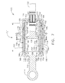
- Rod assembly 100 has a first rod member 112 and a first fitting 114 affixed to first rod member 112.
- First fitting 114 is used for connecting tie rod assembly 100 to a monument or to the structure of the aircraft.
- First fitting 114 can be selected from a variety of connection fittings such as forked, clevis or a threaded end or the like so as to appropriately attach first rod member 112.
- First rod member 112 on an opposing end 116 to first fitting 114 is affixed to enclosure 118.
- Enclosure 118 in this example, is a sealed container that is substantially filled with a fluid such as oil, hydraulic fluid, silicone fluid or the like, which has a viscosity within the range of ten centipoise (10cP) to one thousand centipoise (1000cP).
- Enclosure 118 in this example, is generally cylindrical in shape and is closed at opposing ends, first end 119 and second end 121, of enclosure 118.
- Enclosure 118 also defines opening 120, as seen in FIGS. 6-9 , through which second rod member 122 extends. At least a portion of second rod member 122 is positioned within enclosure 118.
- Enclosure 118 is sealed such that the fluid contained within enclosure 118 is prevented from exiting enclosure 118 with use of O-ring or seal 124 positioned between second rod member 122 and enclosure 118 at opening 120.
- This O-ring or seal 124 or the like such as silicone or the like in this example provides resistance from leaking fluid contained within enclosure 118 with pressures in the range of approximately one hundred pounds per square inch (100psi) and five thousand pounds per square inch (5000psi) exerted onto seal 124.
- a seal or O-rings can be selected from a variety of seals and O-rinks to provide the fluid pressure resistance necessary to resist the fluid pressure to be exerted within enclosure 118 for the particular tie rod assembly 100 in operation.
- Head member 126 is positioned within enclosure 118 and is affixed to second rod member 122. Second rod member 122 and head member 126 are moveable relative to enclosure 118, as will be discussed in more detail herein. As seen in FIG. 5 , second rod member 122 has second fitting 128 affixed to end portion 130 of second rod member 122. Second fitting 128 is used to connect tie rod assembly 100 to the other of the monument or the structure of the aircraft to which first fitting 114 is connected. Similarly, second fitting 128 can be selected from a variety of connection fittings such as forked, clevis or a threaded end or the like so as to appropriately attach second rod member 122.
- Enclosure 118 can be constructed of a material selected from a variety of materials, such as metal or plastic.
- first rod member 112, second rod member 122 and head member 126 can also be constructed of a material selected from a variety of materials such as metal or plastic.
- the materials for tie rod assembly 100 are selected appropriately for the environment in which assembly 100 will used and the forces assembly 100 will engage.
- enclosure 118 includes, in this embodiment, first sidewall 148 connected to first end wall 119 and second end wall 121.
- first sidewall 148 of enclosure 118 is constructed of a cylindrical shape.
- Second sidewall 150 is positioned spaced apart from inner surface 152 of first sidewall 148.
- Second sidewall 150 in this example, is also cylindrical in shape and is positioned concentrically within first sidewall 148.
- second sidewall 150 includes portion 160 which extends from first end wall 119.
- First sidewall 148 connects to and extends between first end wall 119 and second end wall 121.
- Outer surface 154 of second sidewall 150, inner surface 152 of first sidewall 148, first end wall 119 and second end wall 121 define an outer chamber 156 within the enclosure 118.
- Inner surface 157 of the second sidewall 150, the first end wall 119 and second end wall 121 define inner chamber 159 within the enclosure 118.
- First opening 158 is defined in first end portion 160 positioned closer to first end wall 119 than to second end wall 121. In this embodiment, first openings 158 are positioned equally spaced apart about cylindrically shaped second sidewall 150, as seen in FIG. 7 .
- Second opening 162 is defined in second portion 161 of second sidewall 150 positioned closer to second end wall 121 than to first end wall 119. Similarly, in this embodiment, second openings 162 are positioned equally spaced apart about cylindrically shaped second sidewall 150, as seen in FIG. 7 .
- Inner chamber 159 is in fluid communication with outer chamber 156 through first opening 158. Inner chamber 159 is also in fluid communication with outer chamber 156 through second opening 162. Head member 126 is positioned within inner chamber 159 between first and second openings, 158 and 162. Head member 126 has an O-rings or seal 164 positioned between head member 126 and interior surface 157 of second sidewall 150 of enclosure 118. This sealing arrangement utilizing O-rings 164 allows head member 126 to move along interior surface 157 and provide a seal between interior surface 157 and head member 126. This sealing arrangement does not permit fluid contained within enclosure 118 to move between head member 126 and inner surface 157 of second sidewall 150.
- O-ring or seal 164 can be selected from a variety of O-rings or seals, such as silicone, Teflon, Neoprene or rubber and the like. In this example, O-ring 164 will seal a pressure of fluid in the range of one hundred pounds per square inch (100psi) to five thousand pounds per square inch (5000psi). Seals or O-rinks can be selected to provide the fluid pressure resistance necessary to resist the fluid pressure exerted within enclosure 118 onto O-ring or seal 164 for the particular tie rod assembly100 in operation.
- controller 166 is positioned within outer chamber 156.
- Controller 166 includes first hollow body 168 which defines first opening 170 which is defined between first end wall 119 and first hollow body 168.
- First hollow body 168 defines a second opening 174 which is defined between second end wall 121 and first hollow body 168.
- First hollow body 168 extends along and overlies outer surface 154 of second sidewall 150 and in this embodiment, is cylindrical in shape. Length "L" of first hollow body 168 extends between first opening 158 and second opening 162.
- Wall member 178 is connected to first hollow body 168 and is centrally positioned along the length "L" of first hollow body 168 and extends in a direction toward first sidewall 148 of the enclosure 118.
- Second hollow body 184 in this embodiment, is cylindrical in shape. Second hollow body 184 is positioned spaced apart from and extends about first hollow body 168 and is connected to wall member 178. Outer surface 186 of second hollow body 184 is positioned adjacent to inner surface 152 of first sidewall 148 of enclosure 118.
- First spring member 196 is positioned within outer chamber 156 between first side 198 of the wall member 178 and first end wall 119 of the enclosure 118.
- Second spring member 200 is positioned within outer chamber 156 between second side 202 of wall member 178 and second end wall 121 of the enclosure 118.
- wall member 178 defines a plurality of spaced apart openings 204. Openings 204 are positioned equally spaced apart in this embodiment placing outer chamber 156 positioned on first side 198 of the wall member 178 into fluid communication with outer chamber 156 which is positioned on second side 202 of the wall member 178, as seen in FIG. 7 . Size of the radius of openings 204 are calculated as described earlier for openings 36 with knowing the forces for which head member 126 is to move within enclosure 118 during in-flight operational forces being exerted onto tie rod assembly 100 and the viscosity of fluid contained within enclosure 118. Thus, as operational in-flight movements take place, head member 126 will move within enclosure 118 with fluid contained within enclosure 118 passing through openings 204 and not transmit a compression or tension force to fitting 114 and onto the monument to which it is secured.
- a tensile force is placed on second rod member 122 in a direction away from tie rod assembly 100 and first fitting 114, as seen in FIG. 8 .
- a compression force placed on second rod member 122 is in a direction toward tie rod assembly 100 and first fitting 114, as seen in FIG. 9 .
- the movements caused by operation in-flight movements of the aircraft structure exert a force onto head member 126.
- head member 126 exerts a force onto the fluid contained within enclosure 118.
- first opening 158 of second sidewall 150 will push against second side 202 of wall member 178 moving controller 166 in the direction toward first opening 158 of second sidewall 150.
- Wall member 178 pushes against first spring 196 compressing first spring 196.
- Controller 166 based on the extraordinary force, overcomes the resistant force of first spring 196 and first hollow body 168 blocks or closes first openings 158 of second sidewall 150. Closing first openings 158 of second sidewall 150 stops flow of fluid from outer chamber 156 through first opening 158 into inner chamber 159.
- tie rod assembly 100 is fixed and performs as a conventional tie rod.
- second rod member 122 includes visual indicators for properly positioning head member 126 in a central position within enclosure 118. With central positioning of head member 126 within enclosure 118, forces exerted on tie rod assembly 100 will not cause head member 126 to bottom out with respect to end walls 119 and 121 within enclosure 118.
- mark or notch 206 is shown positioned on second rod member 122.
- second rod member 122 includes three successive portions 210, 208 and 212 of surface 214. Portions 210 and 212 which are separated by portion 208. Portions 210 and 212 are the same color that is different from the color for portion 208.
- first fitting 114 and second fitting 128 will secure to the monument and the structure of the aircraft.
- mark or notch 206 will be positioned near end wall 121 indicating head member 126 is centrally positioned within enclosure 118.
- a central portion central portion 208 will be positioned near end wall 121 indicating head member 126 is centrally positioned within enclosure 118.
Landscapes
- Engineering & Computer Science (AREA)
- General Engineering & Computer Science (AREA)
- Mechanical Engineering (AREA)
- Aviation & Aerospace Engineering (AREA)
- Physics & Mathematics (AREA)
- Fluid Mechanics (AREA)
- Earth Drilling (AREA)
- Sealing Devices (AREA)
Applications Claiming Priority (1)
| Application Number | Priority Date | Filing Date | Title |
|---|---|---|---|
| US14/538,947 US9714093B2 (en) | 2014-11-12 | 2014-11-12 | Self-dampening tie-rod |
Publications (2)
| Publication Number | Publication Date |
|---|---|
| EP3020636A1 true EP3020636A1 (fr) | 2016-05-18 |
| EP3020636B1 EP3020636B1 (fr) | 2019-01-09 |
Family
ID=54396764
Family Applications (1)
| Application Number | Title | Priority Date | Filing Date |
|---|---|---|---|
| EP15192542.7A Active EP3020636B1 (fr) | 2014-11-12 | 2015-11-02 | Tirant auto-amortissant |
Country Status (2)
| Country | Link |
|---|---|
| US (1) | US9714093B2 (fr) |
| EP (1) | EP3020636B1 (fr) |
Cited By (1)
| Publication number | Priority date | Publication date | Assignee | Title |
|---|---|---|---|---|
| WO2021156524A1 (fr) * | 2020-02-07 | 2021-08-12 | Junior Derqui, S.L. | Ressort pneumatique à longueur réglable |
Families Citing this family (5)
| Publication number | Priority date | Publication date | Assignee | Title |
|---|---|---|---|---|
| US10201408B2 (en) * | 2015-01-15 | 2019-02-12 | Jbl Radical Innovations, Llc | Dispensing vial |
| DE102015202191B4 (de) * | 2015-02-06 | 2019-07-18 | Saf-Holland Gmbh | Lenkstabilisierung |
| WO2020018532A1 (fr) * | 2018-07-16 | 2020-01-23 | Stabilus Gmbh | Appareil d'amortissement |
| AU2021271942C1 (en) * | 2020-05-11 | 2026-02-26 | Brolock Pty Ltd | A hinge |
| EP4253234B1 (fr) * | 2022-03-28 | 2026-04-29 | B/E Aerospace, Inc. | Tirant d'ancrage absorbant la charge pour intégration de structure d'aéronef |
Citations (8)
| Publication number | Priority date | Publication date | Assignee | Title |
|---|---|---|---|---|
| US3360086A (en) * | 1966-04-12 | 1967-12-26 | Albert C Damske | Means to convert mechanical energy into heat energy in a shock absorber |
| US4492290A (en) * | 1983-01-12 | 1985-01-08 | Maremont Corporation | Acceleration sensitive compression head |
| US5568847A (en) * | 1992-04-10 | 1996-10-29 | Bertin & Cie | Device for providing a rigid mechanical link with frequency cut-off |
| EP0850833A2 (fr) * | 1996-12-23 | 1998-07-01 | The Boeing Company | Toilette escamotable pour avion |
| US20030146343A1 (en) * | 2002-02-06 | 2003-08-07 | Elio Zoppitelli | Dual piston drag damper for rotary-wing aircraft rotor |
| US6644168B1 (en) * | 2002-08-12 | 2003-11-11 | General Dynamics Armament And Technical Products, Inc. | System and method for active control of recoil mechanism |
| DE102007022629A1 (de) * | 2007-05-11 | 2008-11-20 | Fuchs Petrolub Ag | Hydraulischer Schwingungsdämpfer |
| US20100051401A1 (en) * | 2006-02-15 | 2010-03-04 | Airbus Deutschland Gmbh | Force level control for an energy absorber for aircraft |
Family Cites Families (13)
| Publication number | Priority date | Publication date | Assignee | Title |
|---|---|---|---|---|
| US3435700A (en) * | 1967-10-05 | 1969-04-01 | Waldo E Calhoun | Fluid cushioned steering column |
| US3840097A (en) * | 1973-01-22 | 1974-10-08 | Hennells W Co Inc | Adjustable shock absorber |
| US4266639A (en) * | 1979-05-10 | 1981-05-12 | International Telephone And Telegraph Corporation | Quick response hydraulic shock suppressor for piping systems |
| US4673063A (en) * | 1986-05-12 | 1987-06-16 | General Signal Corporation | Hydraulic shock absorber having reserve liquid supply chamber and indicator |
| US4874066A (en) * | 1987-12-04 | 1989-10-17 | S.U.I. Corporation | Variable flow shock absorber and method |
| US5170530A (en) * | 1988-03-10 | 1992-12-15 | Reilor Limited | Door closer |
| US4989537A (en) * | 1989-08-01 | 1991-02-05 | Hutchinson Sr Jerry W | Wear indicator for vehicle air brakes |
| US5351562A (en) * | 1992-01-24 | 1994-10-04 | Keystone Railway Equipment Co., Inc. | Hydraulic--pneumatic cushioning device with pressure indicator |
| US5220706A (en) * | 1992-06-17 | 1993-06-22 | Illinois Tool Works Inc. | Air damper |
| DE69418902T2 (de) * | 1994-03-17 | 1999-12-09 | Andre Ricard | Regel- und modulierbare hydropneumatische dämpfungsvorrichtung |
| US6386311B2 (en) * | 2000-02-18 | 2002-05-14 | Delphi Technologies, Inc. | Limited independent steering device |
| US7066455B2 (en) * | 2003-08-08 | 2006-06-27 | Barnes Group Inc. | Self-centering mechanical strut |
| EP2776735A1 (fr) * | 2011-11-08 | 2014-09-17 | Progressive Suspension, Inc. | Amortisseur sensible à la fréquence |
-
2014
- 2014-11-12 US US14/538,947 patent/US9714093B2/en active Active
-
2015
- 2015-11-02 EP EP15192542.7A patent/EP3020636B1/fr active Active
Patent Citations (8)
| Publication number | Priority date | Publication date | Assignee | Title |
|---|---|---|---|---|
| US3360086A (en) * | 1966-04-12 | 1967-12-26 | Albert C Damske | Means to convert mechanical energy into heat energy in a shock absorber |
| US4492290A (en) * | 1983-01-12 | 1985-01-08 | Maremont Corporation | Acceleration sensitive compression head |
| US5568847A (en) * | 1992-04-10 | 1996-10-29 | Bertin & Cie | Device for providing a rigid mechanical link with frequency cut-off |
| EP0850833A2 (fr) * | 1996-12-23 | 1998-07-01 | The Boeing Company | Toilette escamotable pour avion |
| US20030146343A1 (en) * | 2002-02-06 | 2003-08-07 | Elio Zoppitelli | Dual piston drag damper for rotary-wing aircraft rotor |
| US6644168B1 (en) * | 2002-08-12 | 2003-11-11 | General Dynamics Armament And Technical Products, Inc. | System and method for active control of recoil mechanism |
| US20100051401A1 (en) * | 2006-02-15 | 2010-03-04 | Airbus Deutschland Gmbh | Force level control for an energy absorber for aircraft |
| DE102007022629A1 (de) * | 2007-05-11 | 2008-11-20 | Fuchs Petrolub Ag | Hydraulischer Schwingungsdämpfer |
Non-Patent Citations (1)
| Title |
|---|
| ANONYMOUS: "Monarch XX | SRAM", 8 September 2014 (2014-09-08), XP055262210, Retrieved from the Internet <URL:https://web.archive.org/web/20140908075237/https://www.sram.com/rockshox/products/monarch-xx> [retrieved on 20160401] * |
Cited By (1)
| Publication number | Priority date | Publication date | Assignee | Title |
|---|---|---|---|---|
| WO2021156524A1 (fr) * | 2020-02-07 | 2021-08-12 | Junior Derqui, S.L. | Ressort pneumatique à longueur réglable |
Also Published As
| Publication number | Publication date |
|---|---|
| US9714093B2 (en) | 2017-07-25 |
| EP3020636B1 (fr) | 2019-01-09 |
| US20160130002A1 (en) | 2016-05-12 |
Similar Documents
| Publication | Publication Date | Title |
|---|---|---|
| EP3020636A1 (fr) | Tirant auto-amortissant | |
| US9400223B2 (en) | Retrievable pressure sensor | |
| EP3069994B1 (fr) | Amortisseur de choc | |
| US7954550B2 (en) | Tubing pressure insensitive control system | |
| US20160160955A1 (en) | Suspension damper | |
| NO20160792A1 (en) | Magnetic spring booster for subsurface safety valve | |
| US4307744A (en) | Frangible intertank valve assembly | |
| GB2547493B (en) | Packer | |
| NO20111239A1 (no) | Ankersystem samt fremgangsmate | |
| US20150308222A1 (en) | Self-regulating flow control device | |
| EP2971897B1 (fr) | Ensemble soupape de sûreté à pression | |
| US20150129238A1 (en) | Device for Compensation of Wave Influenced Distance Variations on a Drill String | |
| US20050000695A1 (en) | Filling and circulating apparatus for subsurface exploration | |
| US8936098B2 (en) | System and method for remediating a wellbore annulus | |
| CN106232185A (zh) | 用于在消防操作特别是机场救援环境中使用的刺穿装置 | |
| CN211174940U (zh) | 一种带有自锁机构的安全防护螺栓 | |
| WO2015038004A1 (fr) | Dispositif informatisé pour compenser des variations de distance provoquées par les vagues sur un train de tiges | |
| US10221650B2 (en) | Hydraulic position indicator system | |
| CZ306774B6 (cs) | Rozpínatelný horninový svorník s indikátorem upnutí | |
| US4252188A (en) | Actuator | |
| RU2623612C2 (ru) | Ограничитель скорости движения тела | |
| CN111216906A (zh) | 一种快卸自封式机翼油箱放油装置 | |
| US10371284B2 (en) | Local position indicator for subsea isolation valve having no external position indication | |
| EP3224448B1 (fr) | Ensemble de soupape haute-pression | |
| CN206429459U (zh) | 一种气液隔离的供油系统及压力机 |
Legal Events
| Date | Code | Title | Description |
|---|---|---|---|
| PUAI | Public reference made under article 153(3) epc to a published international application that has entered the european phase |
Free format text: ORIGINAL CODE: 0009012 |
|
| 17P | Request for examination filed |
Effective date: 20151102 |
|
| AK | Designated contracting states |
Kind code of ref document: A1 Designated state(s): AL AT BE BG CH CY CZ DE DK EE ES FI FR GB GR HR HU IE IS IT LI LT LU LV MC MK MT NL NO PL PT RO RS SE SI SK SM TR |
|
| AX | Request for extension of the european patent |
Extension state: BA ME |
|
| GRAP | Despatch of communication of intention to grant a patent |
Free format text: ORIGINAL CODE: EPIDOSNIGR1 |
|
| STAA | Information on the status of an ep patent application or granted ep patent |
Free format text: STATUS: GRANT OF PATENT IS INTENDED |
|
| RIC1 | Information provided on ipc code assigned before grant |
Ipc: F16F 13/00 20060101ALI20180523BHEP Ipc: F16F 9/32 20060101ALI20180523BHEP Ipc: F16F 9/34 20060101ALI20180523BHEP Ipc: B64D 11/00 20060101AFI20180523BHEP Ipc: F16F 9/19 20060101ALI20180523BHEP Ipc: F16F 9/512 20060101ALI20180523BHEP Ipc: F16F 9/06 20060101ALI20180523BHEP |
|
| INTG | Intention to grant announced |
Effective date: 20180614 |
|
| GRAS | Grant fee paid |
Free format text: ORIGINAL CODE: EPIDOSNIGR3 |
|
| GRAA | (expected) grant |
Free format text: ORIGINAL CODE: 0009210 |
|
| STAA | Information on the status of an ep patent application or granted ep patent |
Free format text: STATUS: THE PATENT HAS BEEN GRANTED |
|
| AK | Designated contracting states |
Kind code of ref document: B1 Designated state(s): AL AT BE BG CH CY CZ DE DK EE ES FI FR GB GR HR HU IE IS IT LI LT LU LV MC MK MT NL NO PL PT RO RS SE SI SK SM TR |
|
| REG | Reference to a national code |
Ref country code: GB Ref legal event code: FG4D |
|
| REG | Reference to a national code |
Ref country code: CH Ref legal event code: EP Ref country code: AT Ref legal event code: REF Ref document number: 1086986 Country of ref document: AT Kind code of ref document: T Effective date: 20190115 |
|
| REG | Reference to a national code |
Ref country code: IE Ref legal event code: FG4D |
|
| REG | Reference to a national code |
Ref country code: DE Ref legal event code: R096 Ref document number: 602015023103 Country of ref document: DE |
|
| REG | Reference to a national code |
Ref country code: NL Ref legal event code: MP Effective date: 20190109 |
|
| REG | Reference to a national code |
Ref country code: LT Ref legal event code: MG4D |
|
| PG25 | Lapsed in a contracting state [announced via postgrant information from national office to epo] |
Ref country code: NL Free format text: LAPSE BECAUSE OF FAILURE TO SUBMIT A TRANSLATION OF THE DESCRIPTION OR TO PAY THE FEE WITHIN THE PRESCRIBED TIME-LIMIT Effective date: 20190109 |
|
| REG | Reference to a national code |
Ref country code: AT Ref legal event code: MK05 Ref document number: 1086986 Country of ref document: AT Kind code of ref document: T Effective date: 20190109 |
|
| PG25 | Lapsed in a contracting state [announced via postgrant information from national office to epo] |
Ref country code: NO Free format text: LAPSE BECAUSE OF FAILURE TO SUBMIT A TRANSLATION OF THE DESCRIPTION OR TO PAY THE FEE WITHIN THE PRESCRIBED TIME-LIMIT Effective date: 20190409 Ref country code: FI Free format text: LAPSE BECAUSE OF FAILURE TO SUBMIT A TRANSLATION OF THE DESCRIPTION OR TO PAY THE FEE WITHIN THE PRESCRIBED TIME-LIMIT Effective date: 20190109 Ref country code: LT Free format text: LAPSE BECAUSE OF FAILURE TO SUBMIT A TRANSLATION OF THE DESCRIPTION OR TO PAY THE FEE WITHIN THE PRESCRIBED TIME-LIMIT Effective date: 20190109 Ref country code: PL Free format text: LAPSE BECAUSE OF FAILURE TO SUBMIT A TRANSLATION OF THE DESCRIPTION OR TO PAY THE FEE WITHIN THE PRESCRIBED TIME-LIMIT Effective date: 20190109 Ref country code: ES Free format text: LAPSE BECAUSE OF FAILURE TO SUBMIT A TRANSLATION OF THE DESCRIPTION OR TO PAY THE FEE WITHIN THE PRESCRIBED TIME-LIMIT Effective date: 20190109 Ref country code: PT Free format text: LAPSE BECAUSE OF FAILURE TO SUBMIT A TRANSLATION OF THE DESCRIPTION OR TO PAY THE FEE WITHIN THE PRESCRIBED TIME-LIMIT Effective date: 20190509 Ref country code: SE Free format text: LAPSE BECAUSE OF FAILURE TO SUBMIT A TRANSLATION OF THE DESCRIPTION OR TO PAY THE FEE WITHIN THE PRESCRIBED TIME-LIMIT Effective date: 20190109 |
|
| PG25 | Lapsed in a contracting state [announced via postgrant information from national office to epo] |
Ref country code: LV Free format text: LAPSE BECAUSE OF FAILURE TO SUBMIT A TRANSLATION OF THE DESCRIPTION OR TO PAY THE FEE WITHIN THE PRESCRIBED TIME-LIMIT Effective date: 20190109 Ref country code: RS Free format text: LAPSE BECAUSE OF FAILURE TO SUBMIT A TRANSLATION OF THE DESCRIPTION OR TO PAY THE FEE WITHIN THE PRESCRIBED TIME-LIMIT Effective date: 20190109 Ref country code: GR Free format text: LAPSE BECAUSE OF FAILURE TO SUBMIT A TRANSLATION OF THE DESCRIPTION OR TO PAY THE FEE WITHIN THE PRESCRIBED TIME-LIMIT Effective date: 20190410 Ref country code: BG Free format text: LAPSE BECAUSE OF FAILURE TO SUBMIT A TRANSLATION OF THE DESCRIPTION OR TO PAY THE FEE WITHIN THE PRESCRIBED TIME-LIMIT Effective date: 20190409 Ref country code: HR Free format text: LAPSE BECAUSE OF FAILURE TO SUBMIT A TRANSLATION OF THE DESCRIPTION OR TO PAY THE FEE WITHIN THE PRESCRIBED TIME-LIMIT Effective date: 20190109 Ref country code: IS Free format text: LAPSE BECAUSE OF FAILURE TO SUBMIT A TRANSLATION OF THE DESCRIPTION OR TO PAY THE FEE WITHIN THE PRESCRIBED TIME-LIMIT Effective date: 20190509 |
|
| REG | Reference to a national code |
Ref country code: DE Ref legal event code: R097 Ref document number: 602015023103 Country of ref document: DE |
|
| PG25 | Lapsed in a contracting state [announced via postgrant information from national office to epo] |
Ref country code: DK Free format text: LAPSE BECAUSE OF FAILURE TO SUBMIT A TRANSLATION OF THE DESCRIPTION OR TO PAY THE FEE WITHIN THE PRESCRIBED TIME-LIMIT Effective date: 20190109 Ref country code: AT Free format text: LAPSE BECAUSE OF FAILURE TO SUBMIT A TRANSLATION OF THE DESCRIPTION OR TO PAY THE FEE WITHIN THE PRESCRIBED TIME-LIMIT Effective date: 20190109 Ref country code: AL Free format text: LAPSE BECAUSE OF FAILURE TO SUBMIT A TRANSLATION OF THE DESCRIPTION OR TO PAY THE FEE WITHIN THE PRESCRIBED TIME-LIMIT Effective date: 20190109 Ref country code: SK Free format text: LAPSE BECAUSE OF FAILURE TO SUBMIT A TRANSLATION OF THE DESCRIPTION OR TO PAY THE FEE WITHIN THE PRESCRIBED TIME-LIMIT Effective date: 20190109 Ref country code: IT Free format text: LAPSE BECAUSE OF FAILURE TO SUBMIT A TRANSLATION OF THE DESCRIPTION OR TO PAY THE FEE WITHIN THE PRESCRIBED TIME-LIMIT Effective date: 20190109 Ref country code: EE Free format text: LAPSE BECAUSE OF FAILURE TO SUBMIT A TRANSLATION OF THE DESCRIPTION OR TO PAY THE FEE WITHIN THE PRESCRIBED TIME-LIMIT Effective date: 20190109 Ref country code: CZ Free format text: LAPSE BECAUSE OF FAILURE TO SUBMIT A TRANSLATION OF THE DESCRIPTION OR TO PAY THE FEE WITHIN THE PRESCRIBED TIME-LIMIT Effective date: 20190109 Ref country code: RO Free format text: LAPSE BECAUSE OF FAILURE TO SUBMIT A TRANSLATION OF THE DESCRIPTION OR TO PAY THE FEE WITHIN THE PRESCRIBED TIME-LIMIT Effective date: 20190109 |
|
| PLBE | No opposition filed within time limit |
Free format text: ORIGINAL CODE: 0009261 |
|
| STAA | Information on the status of an ep patent application or granted ep patent |
Free format text: STATUS: NO OPPOSITION FILED WITHIN TIME LIMIT |
|
| PG25 | Lapsed in a contracting state [announced via postgrant information from national office to epo] |
Ref country code: SM Free format text: LAPSE BECAUSE OF FAILURE TO SUBMIT A TRANSLATION OF THE DESCRIPTION OR TO PAY THE FEE WITHIN THE PRESCRIBED TIME-LIMIT Effective date: 20190109 |
|
| 26N | No opposition filed |
Effective date: 20191010 |
|
| REG | Reference to a national code |
Ref country code: DE Ref legal event code: R082 Ref document number: 602015023103 Country of ref document: DE Representative=s name: MAIER, LL.M., MICHAEL C., DE Ref country code: DE Ref legal event code: R082 Ref document number: 602015023103 Country of ref document: DE Representative=s name: BOULT WADE TENNANT LLP, DE |
|
| REG | Reference to a national code |
Ref country code: DE Ref legal event code: R082 Ref document number: 602015023103 Country of ref document: DE Representative=s name: BOULT WADE TENNANT LLP, DE |
|
| PG25 | Lapsed in a contracting state [announced via postgrant information from national office to epo] |
Ref country code: SI Free format text: LAPSE BECAUSE OF FAILURE TO SUBMIT A TRANSLATION OF THE DESCRIPTION OR TO PAY THE FEE WITHIN THE PRESCRIBED TIME-LIMIT Effective date: 20190109 |
|
| PG25 | Lapsed in a contracting state [announced via postgrant information from national office to epo] |
Ref country code: TR Free format text: LAPSE BECAUSE OF FAILURE TO SUBMIT A TRANSLATION OF THE DESCRIPTION OR TO PAY THE FEE WITHIN THE PRESCRIBED TIME-LIMIT Effective date: 20190109 |
|
| REG | Reference to a national code |
Ref country code: CH Ref legal event code: PL |
|
| PG25 | Lapsed in a contracting state [announced via postgrant information from national office to epo] |
Ref country code: LU Free format text: LAPSE BECAUSE OF NON-PAYMENT OF DUE FEES Effective date: 20191102 Ref country code: LI Free format text: LAPSE BECAUSE OF NON-PAYMENT OF DUE FEES Effective date: 20191130 Ref country code: MC Free format text: LAPSE BECAUSE OF FAILURE TO SUBMIT A TRANSLATION OF THE DESCRIPTION OR TO PAY THE FEE WITHIN THE PRESCRIBED TIME-LIMIT Effective date: 20190109 Ref country code: CH Free format text: LAPSE BECAUSE OF NON-PAYMENT OF DUE FEES Effective date: 20191130 |
|
| REG | Reference to a national code |
Ref country code: BE Ref legal event code: MM Effective date: 20191130 |
|
| PG25 | Lapsed in a contracting state [announced via postgrant information from national office to epo] |
Ref country code: IE Free format text: LAPSE BECAUSE OF NON-PAYMENT OF DUE FEES Effective date: 20191102 |
|
| PG25 | Lapsed in a contracting state [announced via postgrant information from national office to epo] |
Ref country code: BE Free format text: LAPSE BECAUSE OF NON-PAYMENT OF DUE FEES Effective date: 20191130 |
|
| PG25 | Lapsed in a contracting state [announced via postgrant information from national office to epo] |
Ref country code: CY Free format text: LAPSE BECAUSE OF FAILURE TO SUBMIT A TRANSLATION OF THE DESCRIPTION OR TO PAY THE FEE WITHIN THE PRESCRIBED TIME-LIMIT Effective date: 20190109 |
|
| PG25 | Lapsed in a contracting state [announced via postgrant information from national office to epo] |
Ref country code: HU Free format text: LAPSE BECAUSE OF FAILURE TO SUBMIT A TRANSLATION OF THE DESCRIPTION OR TO PAY THE FEE WITHIN THE PRESCRIBED TIME-LIMIT; INVALID AB INITIO Effective date: 20151102 Ref country code: MT Free format text: LAPSE BECAUSE OF FAILURE TO SUBMIT A TRANSLATION OF THE DESCRIPTION OR TO PAY THE FEE WITHIN THE PRESCRIBED TIME-LIMIT Effective date: 20190109 |
|
| PG25 | Lapsed in a contracting state [announced via postgrant information from national office to epo] |
Ref country code: MK Free format text: LAPSE BECAUSE OF FAILURE TO SUBMIT A TRANSLATION OF THE DESCRIPTION OR TO PAY THE FEE WITHIN THE PRESCRIBED TIME-LIMIT Effective date: 20190109 |
|
| P01 | Opt-out of the competence of the unified patent court (upc) registered |
Effective date: 20230516 |
|
| PGFP | Annual fee paid to national office [announced via postgrant information from national office to epo] |
Ref country code: DE Payment date: 20251128 Year of fee payment: 11 |
|
| PGFP | Annual fee paid to national office [announced via postgrant information from national office to epo] |
Ref country code: GB Payment date: 20251127 Year of fee payment: 11 |
|
| PGFP | Annual fee paid to national office [announced via postgrant information from national office to epo] |
Ref country code: FR Payment date: 20251125 Year of fee payment: 11 |