EP3020914A2 - Surveillance de puits - Google Patents
Surveillance de puits Download PDFInfo
- Publication number
- EP3020914A2 EP3020914A2 EP15181434.0A EP15181434A EP3020914A2 EP 3020914 A2 EP3020914 A2 EP 3020914A2 EP 15181434 A EP15181434 A EP 15181434A EP 3020914 A2 EP3020914 A2 EP 3020914A2
- Authority
- EP
- European Patent Office
- Prior art keywords
- tubing
- signals
- extension portion
- water
- well
- Prior art date
- Legal status (The legal status is an assumption and is not a legal conclusion. Google has not performed a legal analysis and makes no representation as to the accuracy of the status listed.)
- Granted
Links
Images
Classifications
-
- E—FIXED CONSTRUCTIONS
- E21—EARTH OR ROCK DRILLING; MINING
- E21B—EARTH OR ROCK DRILLING; OBTAINING OIL, GAS, WATER, SOLUBLE OR MELTABLE MATERIALS OR A SLURRY OF MINERALS FROM WELLS
- E21B47/00—Survey of boreholes or wells
- E21B47/04—Measuring depth or liquid level
-
- E—FIXED CONSTRUCTIONS
- E21—EARTH OR ROCK DRILLING; MINING
- E21B—EARTH OR ROCK DRILLING; OBTAINING OIL, GAS, WATER, SOLUBLE OR MELTABLE MATERIALS OR A SLURRY OF MINERALS FROM WELLS
- E21B47/00—Survey of boreholes or wells
- E21B47/04—Measuring depth or liquid level
- E21B47/047—Liquid level
-
- E—FIXED CONSTRUCTIONS
- E21—EARTH OR ROCK DRILLING; MINING
- E21B—EARTH OR ROCK DRILLING; OBTAINING OIL, GAS, WATER, SOLUBLE OR MELTABLE MATERIALS OR A SLURRY OF MINERALS FROM WELLS
- E21B47/00—Survey of boreholes or wells
- E21B47/12—Means for transmitting measuring-signals or control signals from the well to the surface, or from the surface to the well, e.g. for logging while drilling
- E21B47/125—Means for transmitting measuring-signals or control signals from the well to the surface, or from the surface to the well, e.g. for logging while drilling using earth as an electrical conductor
-
- E—FIXED CONSTRUCTIONS
- E21—EARTH OR ROCK DRILLING; MINING
- E21B—EARTH OR ROCK DRILLING; OBTAINING OIL, GAS, WATER, SOLUBLE OR MELTABLE MATERIALS OR A SLURRY OF MINERALS FROM WELLS
- E21B47/00—Survey of boreholes or wells
- E21B47/12—Means for transmitting measuring-signals or control signals from the well to the surface, or from the surface to the well, e.g. for logging while drilling
- E21B47/13—Means for transmitting measuring-signals or control signals from the well to the surface, or from the surface to the well, e.g. for logging while drilling by electromagnetic energy, e.g. radio frequency
-
- G—PHYSICS
- G01—MEASURING; TESTING
- G01V—GEOPHYSICS; GRAVITATIONAL MEASUREMENTS; DETECTING MASSES OR OBJECTS; TAGS
- G01V3/00—Electric or magnetic prospecting or detecting; Measuring magnetic field characteristics of the earth, e.g. declination, deviation
- G01V3/18—Electric or magnetic prospecting or detecting; Measuring magnetic field characteristics of the earth, e.g. declination, deviation specially adapted for well-logging
- G01V3/20—Electric or magnetic prospecting or detecting; Measuring magnetic field characteristics of the earth, e.g. declination, deviation specially adapted for well-logging operating with propagation of electric current
Definitions
- This invention relates to well monitoring methods apparatus and arrangements.
- One of these pieces of information is some indication of the level of water in the formation from which product (i.e. oil and/or gas) is being extracted.
- product i.e. oil and/or gas
- a layer of product in a producing formation there will be a layer of product and below this a layer of water. This water may be naturally present or may be present as a result of it being used to drive the product out of the formation. It is desirable to know where this water level is in relation to the producing portion of the well. This can for example, allow appropriate action to be taken as the water approaches a level such that it would begin to be produced from the well.
- the present invention is directed at providing methods, apparatus, and arrangements which may be used for detecting the level of water in a formation associated with a well.
- downhole water level detecting apparatus for detecting the level of water in a formation in the region of a well installation, the detecting apparatus comprising a transmitter for applying electrical signals to a signalling loop at a first location, which signalling loop comprises downhole metallic structure of the well installation and an earth return, a detector for monitoring electrical signals in the signalling loop, and an evaluation unit arranged for determining a level of water in the formation relative to the downhole metallic structure in dependence on the monitored signals.
- the detector may comprise a receiver for receiving signals from the signalling loop at a second location and the evaluation unit may be arranged for determining a level of water in the formation relative to the downhole metallic structure in dependence on the received signal strength.
- the detector may be arranged to measure signals, for example current flowing, in the metallic structure between two spaced contacts. At least one of the two spaced contacts may be disposed at or in the region of the first location.
- the first location may be downhole in the well installation. In some embodiments, this location may be close to the level at which water can be expected to be found.
- the first location may be above a production packer.
- the transmitter may be arranged to inject signals into tubing of the well installation.
- the transmitter may be arranged to inject signals into the tubing across an insulation joint provided in the tubing.
- the transmitter may be arranged to inject signals into the tubing across a break in the tubing created by milling out a portion of the tubing whilst downhole.
- the apparatus may comprise a downhole tool of which the transmitter is a part and which is arranged to be disposed within the tubing.
- the downhole tool may be moveable within the tubing. This can allow the tool to be located at a position chosen to maximise performance.
- the transmitter may be located at the surface and/or powered from the surface.
- the signals to be applied to the metallic structure or the necessary power to generate such signals may be conducted downhole via a cable to the first location.
- the receiver may be arranged to extract signals from tubing of the well installation.
- the receiver may be arranged to extract signals from the tubing across an insulation joint provided in the tubing.
- the second location may be in the region of the surface of the well. In an alternative both the first and second locations may be downhole.
- the apparatus may comprise a relay station comprising the receiver and an additional transmitter for transmitting signals relating to a level of water in the formation towards the surface. Said signals may be indicative of signal strength detected at the receiver. Said signals may be indicative of a determined water level.
- the relay station may comprise the evaluation unit.
- the apparatus may comprise at least one further relay station comprising an additional receiver for receiving signals from a respective previous relay station and another additional transmitter for onward transmission of signals.
- each, or at least one of the relay stations may comprise a downhole tool, which is arranged to be disposed within the tubing and which may be moveable relative to the tubing.
- each, or at least one of the relay stations may be arranged to transmit and receive across an insulation joint.
- a downhole water level detecting arrangement comprising a detecting apparatus as defined above installed in a well installation in relation to which a water level is to be determined.
- the well installation may have tubing extending further into the formation than is required for product (oil and/or gas) extraction. This can aid in the detection of the water level as changes in received signal strength with water level are greater when the tubing extends into the part of the formation below the water level.
- An extended tubing can also help improve signalling range up towards the surface.
- the well tubing may comprise a non-perforated section below a perforated section.
- the well tubing may be provided with at least one circumferential band of ceramic insulation around its inner and/or outer surface.
- a plurality of axially spaced bands are provided.
- the band or bands are provided on a non-perforated section of tubing below a perforated section. The provision of such bands can aid in the detection of the water level as it rises to and past each band.
- a method for detecting the level of water in a formation in the region of a well installation comprising the steps of:
- the step of monitoring signals may comprise the step of receiving an electrical signal from the signalling loop at a second location; and the step of determining a level of water in the formation may be carried out in dependence on received signal strength.
- the method may comprise the step of ensuring that tubing is provided in the well installation to a depth beyond that required for extraction of product. This may include ensuring that the tubing extends at least to a depth which corresponds to a maximum desirable water level.
- the maximum desirable water level may vary with time and the depth to which the tubing extends may, in some circumstances, be varied within the life of the well in response to the maximum desirable water level.
- the method may be carried out in a well installation having any or all of the features defined above.
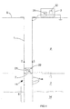
- Figure 1 shows a downhole water level detecting arrangement comprising water level detecting apparatus installed in a well installation.
- the well installation comprises production tubing 1, extending from the surface S down through the formation F to a producing region P where product (i.e. oil/gas) exists within the formation.
- product i.e. oil/gas
- the production tubing 1 has a perforated section 11 with perforations 1 Ia to allow the product to flow into the production tubing 1 and towards the surface.
- water W below the producing region P there exists water W within the formation.
- the tubing 1 will not extend down into this water bearing region of the formation during the typical operation of a producing well.
- the production tubing 1 may be provided with an extension portion E which extends beyond the perforated section 11 further than would normally be the case.
- the extension portion E would be provided without perforations and can extend into the water bearing part W of the formation at least as the water level rises towards the perforated section 11 of the production tubing 1.
- the detecting apparatus comprises a downhole tool 2 which is disposed within the production tubing 1 at a region close to the perforated section 11 of the production tubing 1 and a surface unit 3 located in the region of the well head.
- the downhole tool 2 is arranged for injecting electrical signals into the metallic tubing 1 at the downhole location. These signals are extremely low frequency alternating current signals having a high current. In a typical implementation the frequency of the signals may be in the order of 0.1 Hertz and the applied current may be in the region of 70 Amps.
- the downhole tool 2 comprises a transmitter 21 and conductive centralisers 22 which are arranged to mechanically and electrically contact with the production tubing 1 to allow signals from the transmitter 21 to be fed into the production tubing 1.
- the downhole tool 2 may comprise other components such as a receiver, sensors, and so on, but these are not of particular pertinence to the present invention.
- a signal I propagates away from the tool 2 towards the surface S.
- the strength of the signal I propagated towards the surface is influenced by how good this distributed connection to Earth is. That is to say it is influenced by the impedance seen between the downhole tool 2 and Earth.
- the present techniques use this fact in the detection of the level of water within the formation because the level of water within the formation influences the impedance between the tool 2 and Earth and thus influences the magnitude of the signal I which propagates towards the surface along the production tubing 1.
- the surface unit 3 comprises a receiver 31 which is connected between the production tubing 1 in the region of the well head and Earth for extracting the signal I from the tubing 1.
- the signal strength seen by this receiver 1 varies as the impedance of the signalling loop changes and in particular as the impedance to Earth from the tool 2 changes.
- the received signal strength at the receiver 31 varies as the water level within the formation changes.
- the surface unit 3 comprises an evaluation unit 32 which is calibrated and arranged for giving an indication of the water level relative to the metallic structure 1 of the well in dependence on the signal strength received at the receiver 31.
- the production tubing 1 may be provided with an extension portion E which extends further beyond the perforated section 1, i.e. producing region of the production tubing 1, than would normally be the case.
- This is useful in the present techniques as the degree of change in signal strength that will be seen at the receiver 31 changes much more rapidly as the water level progresses up through the formation in a region where the metallic production tubing 1 is present than when it is progressing up through the formation at a level below which the production tubing stops.
- An extension portion E can assist in signalling range towards the surface.
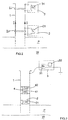
- FIG 2 schematically shows a downhole water level detecting arrangement which is similar to that shown in Figure 1 .
- insulation joints IJ are provided in the production tubing 1 at the region of the downhole tool 2 and the surface unit 3.
- the transmitter 21 of the downhole tool can be connected across an insulation joint as can the receiver 31 of the surface unit 3.
- an insulation joint is provided to electrically insulate one portion of tubing from another.
- the arrangement shown in Figure 1 is more suitable for retro-fitting operations as the downhole tool 2 in that arrangement can be deployed within the tubing 1 in an already completed well. Further it can be used where the inclusion of an insulation joint IJ is not feasible.
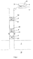
- Figure 3 schematically shows a further downhole water level detecting arrangement which is similar to that shown in Figure 1 and described above.
- a downhole relay station 4 having a receiver 41 for receiving the signals transmitted by the downhole tool 2 and a transmitter 42 for transmitting signals onwards up to the surface unit 3.
- a relay station 4 downhole can help improve the sensitivity of the system whilst giving the desired range.
- a downhole tool 2 of the present type is located close to the end of the production tubing 1 as is desirable in the present case, its range for upward transmission is smaller than when the tool 2 is spaced further from the end of the production tubing 1.
- placing the tool 2 close to the end of the production tubing 1 helps in giving good sensitivity for detecting the water level in the formation.
- the provision of a relay station 4 helps provide an improved system.
- the relay station 4 is arranged for receiving the signal transmitted by the transmitter 21 of the downhole tool 2 and then transmitting, using the transmitter 42, a signal which is indicative of the received signal strength as seen by the receiver 41. This signal which is indicative of the received signal strength at the receiver 41 of the relay station is then received by the surface unit 3 and used by the evaluating unit 32 to provide an indication of the water level.
- the evaluation unit may be provided in the relay station 4 such that a determination of the water level is made in the relay station 4 and a signal which is representative of this water level is transmitted by the relay station 4 onwards towards the surface unit 3.
- Figure 4 shows yet another alternative downhole water level detecting arrangement which is similar to that shown in Figure 3 and described above.
- each relay station 4 and 5 are included each with a receiver, 41, 51 and transmitter 42, 52.
- the functioning and operation of each relay station 4,5 is the same as described above in relation to the relay station 4 of Figure 3 , but the provision of two relay stations allows one of these to be disposed close to the downhole tool 2 to further increase the sensitivity of the detection system whilst still allowing an extended range to the surface.
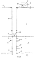
- FIG. 5 shows a further alternative downhole water level detecting arrangement which in this case is similar to that shown in Figure 1 .
- the water level detecting apparatus installed in the well installation of Figure 5 is the same as that installed in the well installation of Figure 1 .
- an extension portion E is provided to the production tubing.
- This extension portion E is a solid walled portion of tubing which extends further down into the well than the perforated portion 11.
- This extension portion E of the production tubing 1 has provided around its external surface a series of axial spaced insulating portions 12.
- each of these insulating portions comprise an insulating ceramic coating.
- These insulating bands 12 change the impedance characteristics of the tubing in terms of conduction to earth. This in turn leads to a modification of the change in signals which will be received at the receiving unit 3 as the water level progresses up the tubing.
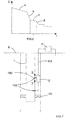
- Figure 6 schematically shows a plot of impedance Z seen between the downhole tool 2 and earth against time t as the water level rises within the well.
- the impedance will be steadily decreasing as shown by portion a of the plot.
- portion b of the plot As the water reaches the bottom of the metallic tubing the impedance will begin to much more rapidly decrease as the water progresses up the tubing and more and more of the tubing is immersed in water - this is shown by portion b of the plot.
- portion b the plot.
- the water reaches an insulated portion 12 of the tubing there will be a slower decrease in impedance as the insulated portion of the tubing does not offer such a good direct conduction path between the water and the tubing.
- Figure 7 shows a further alternative downhole water detecting arrangement which operates on a slightly different basis than those described above.
- the downhole water level detecting arrangement again comprises water level detecting apparatus installed in a well insulation. Again there is production tubing 1 within the well and signals I are applied to this tubing which in turn is connected to earth by virtue of progressing through the formation and production region as in the arrangements described above. Furthermore, this arrangement relies on the fact that the characteristics of the signal path including the production tubing 1 and the formation F will be influenced by the level of water in the formation, in the present arrangement however, power for applying a signal I to the production tubing is provided from the surface S.
- the water level detecting apparatus of the present embodiment comprises a modified downhole tool 2' and a modified surface unit 3'.
- the downhole tool 2' is arranged for injecting the signal I at an injection point 100 into the production string 1 and is arranged to be disposed above a packer 101 in a producing well.
- the modified downhole tool 2' comprises spaced contacts 102 for contacting with the production tubing 1 and is connected via a cable (for example a tubing encapsulated cable - TEC) 103 to the surface unit 3'.
- the modified downhole tool 2' is arranged for detecting the current I injected into the string and in particular flowing in a portion of conductor - ie the tubing 1 - disposed between the locations at which the spaced contacts 102 are located.
- the level of current flowing between these two contacts 102 will be dependent on the impedance between the injection point 100 and earth as via the distributed earth provided by the production tubing. Hence this current level will be dependent on the water level.
- the surface unit 3' may supply power to the downhole tool 2 which is then used to generate the signal for injection at the injection point 100.
- the cable 103 may be used to conduct the signal to be injected directly from the surface unit 3' to the injection point 100.
- readings taken at the downhole tool 2' based on the signals detected by the spaced contacts 101 may be transmitted back to the surface unit 3' via the cable 103.
- the water level detecting arrangement of Figure 7 has the advantage that it is powered from the surface such that a larger number of readings may be taken and/or the system may be operated over a longer time than the systems which make use of a downhole power source, particularly where such a downhole power source would be batteries.
- the modified downhole tool 2' would be arranged for sending back readings along the cable 103 to the surface unit 3' for processing in order to determine the current water level.
- processing can take place at the downhole tool 2' and a processed signal (such as a signal indicative of the current water level) can be passed back via the cable 103 to the surface unit 3'.
- the tubing portion in the region of, and between, the two spaced contacts 102 may be of a corrosion resistant alloy.
- a benefit of this system is that it avoids having to install components deep into the well where this can cause issues by restricting flow.
Landscapes
- Engineering & Computer Science (AREA)
- Life Sciences & Earth Sciences (AREA)
- Physics & Mathematics (AREA)
- Geology (AREA)
- Mining & Mineral Resources (AREA)
- Environmental & Geological Engineering (AREA)
- Geophysics (AREA)
- General Life Sciences & Earth Sciences (AREA)
- Fluid Mechanics (AREA)
- Geochemistry & Mineralogy (AREA)
- Remote Sensing (AREA)
- General Physics & Mathematics (AREA)
- Electromagnetism (AREA)
- Measurement Of Levels Of Liquids Or Fluent Solid Materials (AREA)
- Level Indicators Using A Float (AREA)
Applications Claiming Priority (3)
| Application Number | Priority Date | Filing Date | Title |
|---|---|---|---|
| GB1021230.6A GB2486637A (en) | 2010-12-14 | 2010-12-14 | Downhole water level detecting apparatus and method |
| EP11807962.3A EP2652263B1 (fr) | 2010-12-14 | 2011-12-08 | Surveillance de puits |
| PCT/GB2011/001703 WO2012080692A2 (fr) | 2010-12-14 | 2011-12-08 | Surveillance de puits |
Related Parent Applications (1)
| Application Number | Title | Priority Date | Filing Date |
|---|---|---|---|
| EP11807962.3A Division EP2652263B1 (fr) | 2010-12-14 | 2011-12-08 | Surveillance de puits |
Publications (3)
| Publication Number | Publication Date |
|---|---|
| EP3020914A2 true EP3020914A2 (fr) | 2016-05-18 |
| EP3020914A3 EP3020914A3 (fr) | 2016-06-15 |
| EP3020914B1 EP3020914B1 (fr) | 2019-10-30 |
Family
ID=43567203
Family Applications (2)
| Application Number | Title | Priority Date | Filing Date |
|---|---|---|---|
| EP15181434.0A Active EP3020914B1 (fr) | 2010-12-14 | 2011-12-08 | Surveillance de puits |
| EP11807962.3A Active EP2652263B1 (fr) | 2010-12-14 | 2011-12-08 | Surveillance de puits |
Family Applications After (1)
| Application Number | Title | Priority Date | Filing Date |
|---|---|---|---|
| EP11807962.3A Active EP2652263B1 (fr) | 2010-12-14 | 2011-12-08 | Surveillance de puits |
Country Status (6)
| Country | Link |
|---|---|
| US (2) | US9371727B2 (fr) |
| EP (2) | EP3020914B1 (fr) |
| BR (1) | BR112013014830B1 (fr) |
| CA (1) | CA2821030C (fr) |
| GB (1) | GB2486637A (fr) |
| WO (1) | WO2012080692A2 (fr) |
Families Citing this family (12)
| Publication number | Priority date | Publication date | Assignee | Title |
|---|---|---|---|---|
| AU2013282287A1 (en) * | 2012-06-29 | 2015-01-29 | Wellntel, Inc. | Well head water level sensor |
| US10030502B1 (en) * | 2013-06-28 | 2018-07-24 | Wellntel, Inc | System for well monitoring |
| WO2015196278A1 (fr) * | 2014-06-23 | 2015-12-30 | Evolution Engineering Inc. | Optimisation d'une communication de données de fond de trou avec des capteurs de trépan et des nœuds |
| US10208585B2 (en) | 2015-08-11 | 2019-02-19 | Intrasen, LLC | Groundwater monitoring system and method |
| GB201608765D0 (en) * | 2016-05-18 | 2016-06-29 | Adrok Ltd | Methods for determining material and/or subsurface temperatures |
| GB2553155C (en) | 2016-10-25 | 2024-09-04 | Expro North Sea Ltd | Communication systems and methods |
| WO2018178607A1 (fr) * | 2017-03-31 | 2018-10-04 | Metrol Technology Ltd | Installations de surveillance de puits |
| US10957180B2 (en) * | 2017-05-12 | 2021-03-23 | Robert Levine | Confined space failsafe access system |
| RU2752473C2 (ru) * | 2017-08-07 | 2021-07-28 | Халлибертон Энерджи Сервисез, Инк. | Автоматизированное определение закрывания задвижки и проверка трубопровода |
| CN112097853B (zh) * | 2020-09-24 | 2024-04-12 | 山东向海慧通科技有限公司 | 地下水资源在线监测系统 |
| CN113266343B (zh) * | 2021-06-29 | 2022-04-01 | 华中科技大学 | 一种无线信号传输系统 |
| US20250076239A1 (en) * | 2023-08-30 | 2025-03-06 | Saudi Arabian Oil Company | Methods of identifying types of iron scale |
Family Cites Families (19)
| Publication number | Priority date | Publication date | Assignee | Title |
|---|---|---|---|---|
| JPS6059295A (ja) * | 1983-09-07 | 1985-04-05 | 新日本製鐵株式会社 | 坑井内水位測定方法 |
| US4747451A (en) * | 1987-08-06 | 1988-05-31 | Oil Well Automation, Inc. | Level sensor |
| FR2712627B1 (fr) * | 1993-11-17 | 1996-01-05 | Schlumberger Services Petrol | Procédé et dispositif pour surveiller et/ou étudier un réservoir d'hydrocarbures traversé par un puits. |
| US5926024A (en) * | 1995-01-04 | 1999-07-20 | Atlantic Richfield Company | System and method for measuring fluid properties by forming a coaxial transmission line in a cased well |
| AU5997996A (en) * | 1995-06-08 | 1997-01-09 | Kvass, Claus | Method and apparatus for conversion of sound signals into li ght |
| JPH0996622A (ja) * | 1995-09-29 | 1997-04-08 | Matsushita Electric Ind Co Ltd | ガスセンサおよびその製造方法 |
| US6766854B2 (en) * | 1997-06-02 | 2004-07-27 | Schlumberger Technology Corporation | Well-bore sensor apparatus and method |
| GB9801010D0 (en) * | 1998-01-16 | 1998-03-18 | Flight Refueling Ltd | Data transmission systems |
| FR2807167B1 (fr) * | 2000-03-28 | 2002-12-13 | Schlumberger Services Petrol | Procede pour determiner la resistivite d'une formation traversee par un puits tube |
| US6464008B1 (en) * | 2001-04-25 | 2002-10-15 | Baker Hughes Incorporated | Well completion method and apparatus |
| US6829928B2 (en) * | 2001-08-31 | 2004-12-14 | Christopher J. Milone | Method of accurately gauging groundwater and nonaqueous phase liquid contaminants which eliminates cross contamination between wells |
| FR2830272B1 (fr) | 2001-10-01 | 2004-04-02 | Schlumberger Services Petrol | Dispositif de surveillance ou d'etude d'un reservoir traverse par un puits |
| US7626508B2 (en) * | 2002-03-05 | 2009-12-01 | Aeromesh Corporation | Monitoring system and method |
| FR2838829B1 (fr) | 2002-04-17 | 2004-06-04 | Schlumberger Services Petrol | Procede de determination de la resistivite d'une formation traversee par un puits tube |
| US20040163806A1 (en) * | 2003-02-20 | 2004-08-26 | Hadley James P. | Well monitoring system |
| US7080699B2 (en) * | 2004-01-29 | 2006-07-25 | Schlumberger Technology Corporation | Wellbore communication system |
| US7554458B2 (en) * | 2005-11-17 | 2009-06-30 | Expro North Sea Limited | Downhole communication |
| US20100101774A1 (en) * | 2008-10-29 | 2010-04-29 | Ch2M Hill, Inc. | Measurement and Control of Liquid Level in Wells |
| US8499828B2 (en) | 2009-12-16 | 2013-08-06 | Schlumberger Technology Corporation | Monitoring fluid movement in a formation |
-
2010
- 2010-12-14 GB GB1021230.6A patent/GB2486637A/en not_active Withdrawn
-
2011
- 2011-12-08 EP EP15181434.0A patent/EP3020914B1/fr active Active
- 2011-12-08 US US13/994,295 patent/US9371727B2/en active Active
- 2011-12-08 EP EP11807962.3A patent/EP2652263B1/fr active Active
- 2011-12-08 WO PCT/GB2011/001703 patent/WO2012080692A2/fr not_active Ceased
- 2011-12-08 CA CA2821030A patent/CA2821030C/fr active Active
- 2011-12-08 BR BR112013014830-6A patent/BR112013014830B1/pt active IP Right Grant
-
2016
- 2016-05-19 US US15/159,241 patent/US10704378B2/en active Active
Also Published As
| Publication number | Publication date |
|---|---|
| US20140002088A1 (en) | 2014-01-02 |
| CA2821030C (fr) | 2019-10-22 |
| BR112013014830A2 (pt) | 2016-10-04 |
| EP3020914A3 (fr) | 2016-06-15 |
| BR112013014830B1 (pt) | 2022-02-08 |
| WO2012080692A2 (fr) | 2012-06-21 |
| GB2486637A (en) | 2012-06-27 |
| WO2012080692A3 (fr) | 2013-05-30 |
| EP2652263A2 (fr) | 2013-10-23 |
| US9371727B2 (en) | 2016-06-21 |
| GB201021230D0 (en) | 2011-01-26 |
| EP3020914B1 (fr) | 2019-10-30 |
| US20160258278A1 (en) | 2016-09-08 |
| EP2652263B1 (fr) | 2015-09-09 |
| CA2821030A1 (fr) | 2012-06-21 |
| US10704378B2 (en) | 2020-07-07 |
Similar Documents
| Publication | Publication Date | Title |
|---|---|---|
| US10704378B2 (en) | Well monitoring | |
| JP5723061B2 (ja) | ボーリング孔・地表間電磁送信機 | |
| EP1953570B1 (fr) | Système de télémétrie de fond de trou | |
| US8928488B2 (en) | Signal propagation across gaps | |
| US11156062B2 (en) | Monitoring well installations | |
| WO2017048412A1 (fr) | Dispositifs et procédés pour communiquer des informations depuis le dessous d'un bouchon de surface en ciment dans un puits bouché ou abandonné | |
| US8773278B2 (en) | Apparatus for receiving and transmitting signals in electromagnetic telemetry system used in a wellbore | |
| US10858932B2 (en) | Monitoring well installations | |
| RU2660965C1 (ru) | Магнитолокация с использованием множества скважинных электродов |
Legal Events
| Date | Code | Title | Description |
|---|---|---|---|
| PUAL | Search report despatched |
Free format text: ORIGINAL CODE: 0009013 |
|
| PUAI | Public reference made under article 153(3) epc to a published international application that has entered the european phase |
Free format text: ORIGINAL CODE: 0009012 |
|
| AC | Divisional application: reference to earlier application |
Ref document number: 2652263 Country of ref document: EP Kind code of ref document: P |
|
| AK | Designated contracting states |
Kind code of ref document: A2 Designated state(s): AL AT BE BG CH CY CZ DE DK EE ES FI FR GB GR HR HU IE IS IT LI LT LU LV MC MK MT NL NO PL PT RO RS SE SI SK SM TR |
|
| AK | Designated contracting states |
Kind code of ref document: A3 Designated state(s): AL AT BE BG CH CY CZ DE DK EE ES FI FR GB GR HR HU IE IS IT LI LT LU LV MC MK MT NL NO PL PT RO RS SE SI SK SM TR |
|
| RIC1 | Information provided on ipc code assigned before grant |
Ipc: E21B 47/12 20120101ALI20160510BHEP Ipc: E21B 47/04 20120101AFI20160510BHEP |
|
| STAA | Information on the status of an ep patent application or granted ep patent |
Free format text: STATUS: REQUEST FOR EXAMINATION WAS MADE |
|
| 17P | Request for examination filed |
Effective date: 20161208 |
|
| RBV | Designated contracting states (corrected) |
Designated state(s): AL AT BE BG CH CY CZ DE DK EE ES FI FR GB GR HR HU IE IS IT LI LT LU LV MC MK MT NL NO PL PT RO RS SE SI SK SM TR |
|
| STAA | Information on the status of an ep patent application or granted ep patent |
Free format text: STATUS: EXAMINATION IS IN PROGRESS |
|
| 17Q | First examination report despatched |
Effective date: 20171123 |
|
| GRAJ | Information related to disapproval of communication of intention to grant by the applicant or resumption of examination proceedings by the epo deleted |
Free format text: ORIGINAL CODE: EPIDOSDIGR1 |
|
| STAA | Information on the status of an ep patent application or granted ep patent |
Free format text: STATUS: GRANT OF PATENT IS INTENDED |
|
| GRAP | Despatch of communication of intention to grant a patent |
Free format text: ORIGINAL CODE: EPIDOSNIGR1 |
|
| INTG | Intention to grant announced |
Effective date: 20190605 |
|
| GRAS | Grant fee paid |
Free format text: ORIGINAL CODE: EPIDOSNIGR3 |
|
| GRAA | (expected) grant |
Free format text: ORIGINAL CODE: 0009210 |
|
| STAA | Information on the status of an ep patent application or granted ep patent |
Free format text: STATUS: THE PATENT HAS BEEN GRANTED |
|
| AC | Divisional application: reference to earlier application |
Ref document number: 2652263 Country of ref document: EP Kind code of ref document: P |
|
| AK | Designated contracting states |
Kind code of ref document: B1 Designated state(s): AL AT BE BG CH CY CZ DE DK EE ES FI FR GB GR HR HU IE IS IT LI LT LU LV MC MK MT NL NO PL PT RO RS SE SI SK SM TR |
|
| REG | Reference to a national code |
Ref country code: GB Ref legal event code: FG4D |
|
| REG | Reference to a national code |
Ref country code: CH Ref legal event code: EP |
|
| REG | Reference to a national code |
Ref country code: DE Ref legal event code: R096 Ref document number: 602011063128 Country of ref document: DE |
|
| REG | Reference to a national code |
Ref country code: AT Ref legal event code: REF Ref document number: 1196335 Country of ref document: AT Kind code of ref document: T Effective date: 20191115 |
|
| REG | Reference to a national code |
Ref country code: IE Ref legal event code: FG4D |
|
| REG | Reference to a national code |
Ref country code: NO Ref legal event code: T2 Effective date: 20191030 |
|
| REG | Reference to a national code |
Ref country code: LT Ref legal event code: MG4D |
|
| PG25 | Lapsed in a contracting state [announced via postgrant information from national office to epo] |
Ref country code: GR Free format text: LAPSE BECAUSE OF FAILURE TO SUBMIT A TRANSLATION OF THE DESCRIPTION OR TO PAY THE FEE WITHIN THE PRESCRIBED TIME-LIMIT Effective date: 20200131 Ref country code: PL Free format text: LAPSE BECAUSE OF FAILURE TO SUBMIT A TRANSLATION OF THE DESCRIPTION OR TO PAY THE FEE WITHIN THE PRESCRIBED TIME-LIMIT Effective date: 20191030 Ref country code: LT Free format text: LAPSE BECAUSE OF FAILURE TO SUBMIT A TRANSLATION OF THE DESCRIPTION OR TO PAY THE FEE WITHIN THE PRESCRIBED TIME-LIMIT Effective date: 20191030 Ref country code: NL Free format text: LAPSE BECAUSE OF FAILURE TO SUBMIT A TRANSLATION OF THE DESCRIPTION OR TO PAY THE FEE WITHIN THE PRESCRIBED TIME-LIMIT Effective date: 20191030 Ref country code: PT Free format text: LAPSE BECAUSE OF FAILURE TO SUBMIT A TRANSLATION OF THE DESCRIPTION OR TO PAY THE FEE WITHIN THE PRESCRIBED TIME-LIMIT Effective date: 20200302 Ref country code: SE Free format text: LAPSE BECAUSE OF FAILURE TO SUBMIT A TRANSLATION OF THE DESCRIPTION OR TO PAY THE FEE WITHIN THE PRESCRIBED TIME-LIMIT Effective date: 20191030 Ref country code: LV Free format text: LAPSE BECAUSE OF FAILURE TO SUBMIT A TRANSLATION OF THE DESCRIPTION OR TO PAY THE FEE WITHIN THE PRESCRIBED TIME-LIMIT Effective date: 20191030 Ref country code: FI Free format text: LAPSE BECAUSE OF FAILURE TO SUBMIT A TRANSLATION OF THE DESCRIPTION OR TO PAY THE FEE WITHIN THE PRESCRIBED TIME-LIMIT Effective date: 20191030 Ref country code: BG Free format text: LAPSE BECAUSE OF FAILURE TO SUBMIT A TRANSLATION OF THE DESCRIPTION OR TO PAY THE FEE WITHIN THE PRESCRIBED TIME-LIMIT Effective date: 20200130 |
|
| REG | Reference to a national code |
Ref country code: NL Ref legal event code: MP Effective date: 20191030 |
|
| PG25 | Lapsed in a contracting state [announced via postgrant information from national office to epo] |
Ref country code: IS Free format text: LAPSE BECAUSE OF FAILURE TO SUBMIT A TRANSLATION OF THE DESCRIPTION OR TO PAY THE FEE WITHIN THE PRESCRIBED TIME-LIMIT Effective date: 20200229 Ref country code: RS Free format text: LAPSE BECAUSE OF FAILURE TO SUBMIT A TRANSLATION OF THE DESCRIPTION OR TO PAY THE FEE WITHIN THE PRESCRIBED TIME-LIMIT Effective date: 20191030 Ref country code: HR Free format text: LAPSE BECAUSE OF FAILURE TO SUBMIT A TRANSLATION OF THE DESCRIPTION OR TO PAY THE FEE WITHIN THE PRESCRIBED TIME-LIMIT Effective date: 20191030 |
|
| PG25 | Lapsed in a contracting state [announced via postgrant information from national office to epo] |
Ref country code: AL Free format text: LAPSE BECAUSE OF FAILURE TO SUBMIT A TRANSLATION OF THE DESCRIPTION OR TO PAY THE FEE WITHIN THE PRESCRIBED TIME-LIMIT Effective date: 20191030 |
|
| REG | Reference to a national code |
Ref country code: DE Ref legal event code: R119 Ref document number: 602011063128 Country of ref document: DE |
|
| PG25 | Lapsed in a contracting state [announced via postgrant information from national office to epo] |
Ref country code: ES Free format text: LAPSE BECAUSE OF FAILURE TO SUBMIT A TRANSLATION OF THE DESCRIPTION OR TO PAY THE FEE WITHIN THE PRESCRIBED TIME-LIMIT Effective date: 20191030 Ref country code: DK Free format text: LAPSE BECAUSE OF FAILURE TO SUBMIT A TRANSLATION OF THE DESCRIPTION OR TO PAY THE FEE WITHIN THE PRESCRIBED TIME-LIMIT Effective date: 20191030 Ref country code: CZ Free format text: LAPSE BECAUSE OF FAILURE TO SUBMIT A TRANSLATION OF THE DESCRIPTION OR TO PAY THE FEE WITHIN THE PRESCRIBED TIME-LIMIT Effective date: 20191030 Ref country code: EE Free format text: LAPSE BECAUSE OF FAILURE TO SUBMIT A TRANSLATION OF THE DESCRIPTION OR TO PAY THE FEE WITHIN THE PRESCRIBED TIME-LIMIT Effective date: 20191030 Ref country code: RO Free format text: LAPSE BECAUSE OF FAILURE TO SUBMIT A TRANSLATION OF THE DESCRIPTION OR TO PAY THE FEE WITHIN THE PRESCRIBED TIME-LIMIT Effective date: 20191030 |
|
| REG | Reference to a national code |
Ref country code: CH Ref legal event code: PL |
|
| REG | Reference to a national code |
Ref country code: AT Ref legal event code: MK05 Ref document number: 1196335 Country of ref document: AT Kind code of ref document: T Effective date: 20191030 |
|
| REG | Reference to a national code |
Ref country code: BE Ref legal event code: MM Effective date: 20191231 |
|
| PG25 | Lapsed in a contracting state [announced via postgrant information from national office to epo] |
Ref country code: SK Free format text: LAPSE BECAUSE OF FAILURE TO SUBMIT A TRANSLATION OF THE DESCRIPTION OR TO PAY THE FEE WITHIN THE PRESCRIBED TIME-LIMIT Effective date: 20191030 Ref country code: MC Free format text: LAPSE BECAUSE OF FAILURE TO SUBMIT A TRANSLATION OF THE DESCRIPTION OR TO PAY THE FEE WITHIN THE PRESCRIBED TIME-LIMIT Effective date: 20191030 Ref country code: SM Free format text: LAPSE BECAUSE OF FAILURE TO SUBMIT A TRANSLATION OF THE DESCRIPTION OR TO PAY THE FEE WITHIN THE PRESCRIBED TIME-LIMIT Effective date: 20191030 Ref country code: IT Free format text: LAPSE BECAUSE OF FAILURE TO SUBMIT A TRANSLATION OF THE DESCRIPTION OR TO PAY THE FEE WITHIN THE PRESCRIBED TIME-LIMIT Effective date: 20191030 |
|
| PLBE | No opposition filed within time limit |
Free format text: ORIGINAL CODE: 0009261 |
|
| STAA | Information on the status of an ep patent application or granted ep patent |
Free format text: STATUS: NO OPPOSITION FILED WITHIN TIME LIMIT |
|
| 26N | No opposition filed |
Effective date: 20200731 |
|
| PG25 | Lapsed in a contracting state [announced via postgrant information from national office to epo] |
Ref country code: DE Free format text: LAPSE BECAUSE OF NON-PAYMENT OF DUE FEES Effective date: 20200701 Ref country code: LU Free format text: LAPSE BECAUSE OF NON-PAYMENT OF DUE FEES Effective date: 20191208 Ref country code: IE Free format text: LAPSE BECAUSE OF NON-PAYMENT OF DUE FEES Effective date: 20191208 Ref country code: FR Free format text: LAPSE BECAUSE OF NON-PAYMENT OF DUE FEES Effective date: 20191230 |
|
| PG25 | Lapsed in a contracting state [announced via postgrant information from national office to epo] |
Ref country code: AT Free format text: LAPSE BECAUSE OF FAILURE TO SUBMIT A TRANSLATION OF THE DESCRIPTION OR TO PAY THE FEE WITHIN THE PRESCRIBED TIME-LIMIT Effective date: 20191030 Ref country code: BE Free format text: LAPSE BECAUSE OF NON-PAYMENT OF DUE FEES Effective date: 20191231 Ref country code: CH Free format text: LAPSE BECAUSE OF NON-PAYMENT OF DUE FEES Effective date: 20191231 Ref country code: LI Free format text: LAPSE BECAUSE OF NON-PAYMENT OF DUE FEES Effective date: 20191231 Ref country code: SI Free format text: LAPSE BECAUSE OF FAILURE TO SUBMIT A TRANSLATION OF THE DESCRIPTION OR TO PAY THE FEE WITHIN THE PRESCRIBED TIME-LIMIT Effective date: 20191030 |
|
| PG25 | Lapsed in a contracting state [announced via postgrant information from national office to epo] |
Ref country code: CY Free format text: LAPSE BECAUSE OF FAILURE TO SUBMIT A TRANSLATION OF THE DESCRIPTION OR TO PAY THE FEE WITHIN THE PRESCRIBED TIME-LIMIT Effective date: 20191030 |
|
| PG25 | Lapsed in a contracting state [announced via postgrant information from national office to epo] |
Ref country code: HU Free format text: LAPSE BECAUSE OF FAILURE TO SUBMIT A TRANSLATION OF THE DESCRIPTION OR TO PAY THE FEE WITHIN THE PRESCRIBED TIME-LIMIT; INVALID AB INITIO Effective date: 20111208 Ref country code: MT Free format text: LAPSE BECAUSE OF FAILURE TO SUBMIT A TRANSLATION OF THE DESCRIPTION OR TO PAY THE FEE WITHIN THE PRESCRIBED TIME-LIMIT Effective date: 20191030 |
|
| PG25 | Lapsed in a contracting state [announced via postgrant information from national office to epo] |
Ref country code: TR Free format text: LAPSE BECAUSE OF FAILURE TO SUBMIT A TRANSLATION OF THE DESCRIPTION OR TO PAY THE FEE WITHIN THE PRESCRIBED TIME-LIMIT Effective date: 20191030 |
|
| PG25 | Lapsed in a contracting state [announced via postgrant information from national office to epo] |
Ref country code: MK Free format text: LAPSE BECAUSE OF FAILURE TO SUBMIT A TRANSLATION OF THE DESCRIPTION OR TO PAY THE FEE WITHIN THE PRESCRIBED TIME-LIMIT Effective date: 20191030 |
|
| P01 | Opt-out of the competence of the unified patent court (upc) registered |
Effective date: 20230512 |
|
| PGFP | Annual fee paid to national office [announced via postgrant information from national office to epo] |
Ref country code: GB Payment date: 20251001 Year of fee payment: 15 |
|
| PGFP | Annual fee paid to national office [announced via postgrant information from national office to epo] |
Ref country code: NO Payment date: 20251210 Year of fee payment: 15 |