EP3020917A1 - Machine hydraulique à palettes - Google Patents
Machine hydraulique à palettes Download PDFInfo
- Publication number
- EP3020917A1 EP3020917A1 EP14193256.6A EP14193256A EP3020917A1 EP 3020917 A1 EP3020917 A1 EP 3020917A1 EP 14193256 A EP14193256 A EP 14193256A EP 3020917 A1 EP3020917 A1 EP 3020917A1
- Authority
- EP
- European Patent Office
- Prior art keywords
- rotor
- machine according
- stator
- vane machine
- wings
- Prior art date
- Legal status (The legal status is an assumption and is not a legal conclusion. Google has not performed a legal analysis and makes no representation as to the accuracy of the status listed.)
- Granted
Links
Images


Classifications
-
- F—MECHANICAL ENGINEERING; LIGHTING; HEATING; WEAPONS; BLASTING
- F01—MACHINES OR ENGINES IN GENERAL; ENGINE PLANTS IN GENERAL; STEAM ENGINES
- F01C—ROTARY-PISTON OR OSCILLATING-PISTON MACHINES OR ENGINES
- F01C21/00—Component parts, details or accessories not provided for in groups F01C1/00 - F01C20/00
- F01C21/08—Rotary pistons
- F01C21/0809—Construction of vanes or vane holders
-
- F—MECHANICAL ENGINEERING; LIGHTING; HEATING; WEAPONS; BLASTING
- F01—MACHINES OR ENGINES IN GENERAL; ENGINE PLANTS IN GENERAL; STEAM ENGINES
- F01C—ROTARY-PISTON OR OSCILLATING-PISTON MACHINES OR ENGINES
- F01C1/00—Rotary-piston machines or engines
- F01C1/30—Rotary-piston machines or engines having the characteristics covered by two or more groups F01C1/02, F01C1/08, F01C1/22, F01C1/24 or having the characteristics covered by one of these groups together with some other type of movement between co-operating members
- F01C1/34—Rotary-piston machines or engines having the characteristics covered by two or more groups F01C1/02, F01C1/08, F01C1/22, F01C1/24 or having the characteristics covered by one of these groups together with some other type of movement between co-operating members having the movement defined in group F01C1/08 or F01C1/22 and relative reciprocation between the co-operating members
- F01C1/344—Rotary-piston machines or engines having the characteristics covered by two or more groups F01C1/02, F01C1/08, F01C1/22, F01C1/24 or having the characteristics covered by one of these groups together with some other type of movement between co-operating members having the movement defined in group F01C1/08 or F01C1/22 and relative reciprocation between the co-operating members with vanes reciprocating with respect to the inner member
- F01C1/3448—Rotary-piston machines or engines having the characteristics covered by two or more groups F01C1/02, F01C1/08, F01C1/22, F01C1/24 or having the characteristics covered by one of these groups together with some other type of movement between co-operating members having the movement defined in group F01C1/08 or F01C1/22 and relative reciprocation between the co-operating members with vanes reciprocating with respect to the inner member with axially movable vanes
-
- F—MECHANICAL ENGINEERING; LIGHTING; HEATING; WEAPONS; BLASTING
- F01—MACHINES OR ENGINES IN GENERAL; ENGINE PLANTS IN GENERAL; STEAM ENGINES
- F01C—ROTARY-PISTON OR OSCILLATING-PISTON MACHINES OR ENGINES
- F01C21/00—Component parts, details or accessories not provided for in groups F01C1/00 - F01C20/00
- F01C21/08—Rotary pistons
- F01C21/0809—Construction of vanes or vane holders
- F01C21/0818—Vane tracking; control therefor
- F01C21/0827—Vane tracking; control therefor by mechanical means
- F01C21/0836—Vane tracking; control therefor by mechanical means comprising guiding means, e.g. cams, rollers
-
- F—MECHANICAL ENGINEERING; LIGHTING; HEATING; WEAPONS; BLASTING
- F01—MACHINES OR ENGINES IN GENERAL; ENGINE PLANTS IN GENERAL; STEAM ENGINES
- F01C—ROTARY-PISTON OR OSCILLATING-PISTON MACHINES OR ENGINES
- F01C21/00—Component parts, details or accessories not provided for in groups F01C1/00 - F01C20/00
- F01C21/10—Outer members for co-operation with rotary pistons; Casings
- F01C21/104—Stators; Members defining the outer boundaries of the working chamber
- F01C21/106—Stators; Members defining the outer boundaries of the working chamber with a radial surface, e.g. cam rings
-
- F—MECHANICAL ENGINEERING; LIGHTING; HEATING; WEAPONS; BLASTING
- F04—POSITIVE - DISPLACEMENT MACHINES FOR LIQUIDS; PUMPS FOR LIQUIDS OR ELASTIC FLUIDS
- F04C—ROTARY-PISTON, OR OSCILLATING-PISTON, POSITIVE-DISPLACEMENT MACHINES FOR LIQUIDS; ROTARY-PISTON, OR OSCILLATING-PISTON, POSITIVE-DISPLACEMENT PUMPS
- F04C18/00—Rotary-piston pumps specially adapted for elastic fluids
- F04C18/30—Rotary-piston pumps specially adapted for elastic fluids having the characteristics covered by two or more of groups F04C18/02, F04C18/08, F04C18/22, F04C18/24, F04C18/48, or having the characteristics covered by one of these groups together with some other type of movement between co-operating members
- F04C18/34—Rotary-piston pumps specially adapted for elastic fluids having the characteristics covered by two or more of groups F04C18/02, F04C18/08, F04C18/22, F04C18/24, F04C18/48, or having the characteristics covered by one of these groups together with some other type of movement between co-operating members having the movement defined in group F04C18/08 or F04C18/22 and relative reciprocation between the co-operating members
- F04C18/344—Rotary-piston pumps specially adapted for elastic fluids having the characteristics covered by two or more of groups F04C18/02, F04C18/08, F04C18/22, F04C18/24, F04C18/48, or having the characteristics covered by one of these groups together with some other type of movement between co-operating members having the movement defined in group F04C18/08 or F04C18/22 and relative reciprocation between the co-operating members with vanes reciprocating with respect to the inner member
- F04C18/3448—Rotary-piston pumps specially adapted for elastic fluids having the characteristics covered by two or more of groups F04C18/02, F04C18/08, F04C18/22, F04C18/24, F04C18/48, or having the characteristics covered by one of these groups together with some other type of movement between co-operating members having the movement defined in group F04C18/08 or F04C18/22 and relative reciprocation between the co-operating members with vanes reciprocating with respect to the inner member with axially movable vanes
-
- F—MECHANICAL ENGINEERING; LIGHTING; HEATING; WEAPONS; BLASTING
- F04—POSITIVE - DISPLACEMENT MACHINES FOR LIQUIDS; PUMPS FOR LIQUIDS OR ELASTIC FLUIDS
- F04C—ROTARY-PISTON, OR OSCILLATING-PISTON, POSITIVE-DISPLACEMENT MACHINES FOR LIQUIDS; ROTARY-PISTON, OR OSCILLATING-PISTON, POSITIVE-DISPLACEMENT PUMPS
- F04C2/00—Rotary-piston machines or pumps
- F04C2/30—Rotary-piston machines or pumps having the characteristics covered by two or more groups F04C2/02, F04C2/08, F04C2/22, F04C2/24 or having the characteristics covered by one of these groups together with some other type of movement between co-operating members
- F04C2/34—Rotary-piston machines or pumps having the characteristics covered by two or more groups F04C2/02, F04C2/08, F04C2/22, F04C2/24 or having the characteristics covered by one of these groups together with some other type of movement between co-operating members having the movement defined in groups F04C2/08 or F04C2/22 and relative reciprocation between the co-operating members
- F04C2/344—Rotary-piston machines or pumps having the characteristics covered by two or more groups F04C2/02, F04C2/08, F04C2/22, F04C2/24 or having the characteristics covered by one of these groups together with some other type of movement between co-operating members having the movement defined in groups F04C2/08 or F04C2/22 and relative reciprocation between the co-operating members with vanes reciprocating with respect to the inner member
- F04C2/3446—Rotary-piston machines or pumps having the characteristics covered by two or more groups F04C2/02, F04C2/08, F04C2/22, F04C2/24 or having the characteristics covered by one of these groups together with some other type of movement between co-operating members having the movement defined in groups F04C2/08 or F04C2/22 and relative reciprocation between the co-operating members with vanes reciprocating with respect to the inner member the inner and outer member being in contact along more than one line or surface
-
- F—MECHANICAL ENGINEERING; LIGHTING; HEATING; WEAPONS; BLASTING
- F04—POSITIVE - DISPLACEMENT MACHINES FOR LIQUIDS; PUMPS FOR LIQUIDS OR ELASTIC FLUIDS
- F04C—ROTARY-PISTON, OR OSCILLATING-PISTON, POSITIVE-DISPLACEMENT MACHINES FOR LIQUIDS; ROTARY-PISTON, OR OSCILLATING-PISTON, POSITIVE-DISPLACEMENT PUMPS
- F04C2/00—Rotary-piston machines or pumps
- F04C2/30—Rotary-piston machines or pumps having the characteristics covered by two or more groups F04C2/02, F04C2/08, F04C2/22, F04C2/24 or having the characteristics covered by one of these groups together with some other type of movement between co-operating members
- F04C2/34—Rotary-piston machines or pumps having the characteristics covered by two or more groups F04C2/02, F04C2/08, F04C2/22, F04C2/24 or having the characteristics covered by one of these groups together with some other type of movement between co-operating members having the movement defined in groups F04C2/08 or F04C2/22 and relative reciprocation between the co-operating members
- F04C2/344—Rotary-piston machines or pumps having the characteristics covered by two or more groups F04C2/02, F04C2/08, F04C2/22, F04C2/24 or having the characteristics covered by one of these groups together with some other type of movement between co-operating members having the movement defined in groups F04C2/08 or F04C2/22 and relative reciprocation between the co-operating members with vanes reciprocating with respect to the inner member
- F04C2/3448—Rotary-piston machines or pumps having the characteristics covered by two or more groups F04C2/02, F04C2/08, F04C2/22, F04C2/24 or having the characteristics covered by one of these groups together with some other type of movement between co-operating members having the movement defined in groups F04C2/08 or F04C2/22 and relative reciprocation between the co-operating members with vanes reciprocating with respect to the inner member with axially movable vanes
Definitions
- the invention relates to a hydraulic vane machine with a stator and a rotor having a plurality of vanes, which are each radially displaceable in a guide in the rotor, abut against an inner circumference of the stator and with the rotor, the stator and one side wall at each axial end of the rotor limit working chambers whose volumes change with rotation of the rotor relative to the stator.
- Such a vane machine is off US Pat. No. 6,684,847 B1 known.
- the wings are provided at both axial ends with projections which are respectively guided in grooves provided in the stator. The course of the grooves determines the movement of the wings.
- Such a vane machine can be used for example as a boost pump in a reverse osmosis system and then acts as a water hydraulic machine.
- the rotor is mounted eccentrically to the inner circumference of the stator. One point on the surface of the rotor then once approaches the inner circumference in one revolution until a minimum distance is reached, and then moves away from the inner circumference until a maximum distance is reached. If the vane machine is used as a pump, then an outlet opening for the respective working chamber is provided in the region of the minimum distance, from which then water can be discharged at a higher pressure. If the vane machine is used as a motor, then there is a feed or supply port in this area, can be fed to the pressurized water.
- the invention has for its object to have a certain freedom in the design of the inner circumference. This object is achieved in a hydraulic vane machine of the type mentioned above in that each wing has on its radially inner side a contact surface which rests radially outward on a cam.
- the abutment surface is formed on at least one axial end of the wings.
- the cam can arrange the cam on an axial end face of the rotor, so that the structure of the rotor is not disturbed or impaired by the use of the cam.
- the abutment surface is formed in a recess at the axial end of the wing. In this recess engages the cam. This makes it possible that the cam covers the wings slightly in the radial direction.
- the wings project axially beyond the rotor.
- the recess has a radial extent that is greater than a maximum stroke of the wing.
- the cam thus covers the wings in the region of the recess over the entire stroke.
- the cam thus serves with the axial sealing of the wings, so that leakage can be avoided or at least kept small.
- the recess has an axial extent corresponding to an axial thickness of the cam.
- the wings abut outside the recess with its axial end on the side wall and within the recess with its axial end on the cam. This results over the entire height of the wings in each angular position of the rotor relative to the stationary parts a sealing surface which extends over the entire radial length of the axial ends of the wings. This ensures a relatively good tightness.
- the cam corresponds to the inner circumference of the stator reduced by twice the radial extent the wing plus twice the radial extent of the recess. This is a relatively simple design rule. You can form the cam so to speak as a reduced copy of the inner circumference of the stator.
- the contact surface is rounded. This keeps friction between the wing and the cam small. It is practically unavoidable that the wing tilts in the guide. Although this tilting can be kept very small, problems could arise as a result of this tilting. Such problems are reliably prevented by the rounding of the contact surface.
- the rotor is mounted centrically relative to the stator and a profile of a radial distance between the stator and the rotor has in the circumferential direction at least two maxima and two minima.
- the rotor has a passage opening, which widens axially inward to a cavity, for receiving an axle.
- the cavity serves to reduce the mass of the rotor.
- the wings enter with their radial inner side in an inward stroke into the cavity. Then, while the cavity is filled with water when the machine is operated. But this is not critical, because the pressure of the water in the cavity can adjust to an average value.
- the wings on a core of a steel and a coating of a steel friction-co-operating plastic.
- the rotor and the stator can be made of steel. Since water has no lubricating properties, the friction reduction caused by a hydraulic oil in an oil-hydraulic machine is in this case effected by the friction-reducing plastic.
- materials from the group of high-strength thermoplastics based on polyaryl ether ketones in particular polyether ether ketones, polyamides, polyacetals, polyaryl ethers, polyethylene terephthalates, polyphenylene sulfides, polysulfones, polyethersulfones, polyetherimides, polyamideimides, polyacrylates, phenol resins, such as novolak, are used as the plastic for the coating Resins, or the like, wherein as fillers glass, graphite, polytetrafluoroethylene or plastic, in particular in fiber form, can be used. When using such materials, water can also be used as hydraulic fluid.
- each vane in the region of the guide has a surface formed from the plastic with a low-friction cooperating plastic surface and the abutment surface is at least partially formed of a steel, wherein the cam at least in an area in which abuts the contact surface, a from a Having formed with plastic friction co-operating plastic surface.
- the cam at least in an area in which abuts the contact surface, a from a Having formed with plastic friction co-operating plastic surface.
- the cam is formed integrally with the side plate. It may for example be formed by a projection on the side plate.
- At least one side wall has at least one opening which is bounded radially on the outside by a web on which the wings abut. Also in the region of the opening is thus achieved that the wings are supported in the axial direction radially inward and radially outward. A tilting of the wings in a direction parallel to the axis of rotation can thus be reliably avoided.
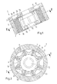
- a vane machine 1 has a stator 2 and a rotor 3, which are rotatably mounted to each other by means not shown.
- the rotor 3 has a plurality of wings 4, which are each radially displaceable in a guide 5 in the rotor 3.
- the wings 4 abut against an inner periphery 6 of the stator.
- a side wall 7 is arranged.
- openings 8, 9 may be provided, which can be used for the supply or for the discharge of water.
- Fig. 1 only one side wall 7 is shown.
- On the axially opposite end side of the stator 2 also has a side wall, which, however, is not shown. In this other side wall you can omit the openings 8, 9 under certain circumstances.
- the openings 8, 9 extend radially outward not quite to the stator 2. Rather, radially outward webs 10, 11 are provided, on which the wings 4 can rest in the axial direction when the rotor rotates. Also in the region of the openings 9, 10 so the wings are supported radially inward and radially outward in the axial direction.
- a through hole 12 is provided, through which, for example, a shaft can be guided, with which the rotor 3 is rotatably mounted relative to the stator 2.
- the passage opening 12 widens to a cavity 13.
- the wings 4 enter with their radial inner sides 14 in the cavity 13 when they are pressed by the inner periphery 6 of the stator 2 radially inward.
- a cam 15 is arranged in each case.
- the cam 15 may be fixed to the side wall 7 or formed integrally with the side wall 7. It has a shape that corresponds to the inner circumference 6 of the stator, but in a reduced version, as will be explained in more detail below.
- the wings 4 each have a recess 16 at its two axial ends. In this recess 16, the cam 15 engages. Each recess 16 has an axial extent corresponding to the axial thickness of the cam 15. The wings 4 are about this axial extent axially over the rotor 3, so that it is possible to make the wings 4 and the cam 15 in the axial direction flush with each other.
- the recesses 16 may have an extent in the radial direction, which is greater than a maximum stroke of the wing.
- the cam 15 then covers the wings 4 over their entire radial stroke in the region of the recess 16.
- the inner circumference 6 of the stator is about twice the radial Extension of the wings 4 reduced. Added twice the radial extent of the recesses 16. With such a shaped cam 15 ensures that the wings 4 always rest on the inner circumference 6 of the stator 2 and there ensure adequate sealing.
- the wings 4 abut with their front side either on the side wall 7 or on the cam 4, so that even there is given a sufficient seal.
- a seal radially inward results from the interaction of the wings 4 with the guides 5.
- the vane machine 1 shown there has two cycles per revolution.
- the result is a minimum distance between the inner periphery 6 of the stator 2 and the rotor 3 at points of the rotor 3, which point upwards and downwards, and a maximum distance at points which point to the left and to the right. Since a "delivery stroke" can always be realized when the maximum distance to the minimum distance decreases, the result in Fig. 2 illustrated embodiments two cycles per revolution. This possibility is provided by the cam 15.
- FIGS Fig. 1 and 2 show the vane machine 1 in perspective view. Same parts are denoted by the same reference numerals as in FIGS Fig. 1 and 2 Mistake.
- the cam 15 is formed here as a separate element. However, it may also be formed integrally with the side wall 7.
- cam 15 If one forms the cam 15 as a separate element, then you can dimension their two faces or pressure application surfaces on the two end faces, which can be defined for example by seals, not shown, so that there is a force balance on the rotor in the axial direction. This allows you to minimize a game and accordingly keep a small leak.
- the wings 4 have a core of a steel and a coating of a plastic friction-co-operating with steel.
- the wings 4 are designed so that they can interact with low friction with the stator 2 and the guides 5 in the rotor 3. Also at their end faces, which bear against the side wall 7 formed of steel, results in a reduced friction.
- plastics it is possible to use, for example, materials from the group of high-strength thermoplastics based on polyaryl ether ketones, in particular polyether ether ketones, Polyamides, polyacetals, polyaryl ethers, polyethylene terephthalates, polyphenylene sulfides, polysulfones, polyethersulfones, polyetherimides, polyamideimides, polyacrylates, phenolic resins such as novolak resins or the like, which may be glass, graphite, polytetrafluoroethylene or plastic, especially in fibrous form, as fillers , When using such materials, water can also be used as hydraulic fluid.
- polyaryl ether ketones polyether ether ketones
- the cam 15 should be provided with a corresponding plastic, at least in the area where the rotor 3 rests with its front side.
- the recesses 6 are expediently milled out of the wings 4 after the plastic has been applied , This results in the contact surface 17, an area which is at least partially formed of a steel and then rests against the plastic of the cam 15. Due to the rounded shape of the contact surface 17 can also be achieved that a contact between the plastic of the wing 4 and the plastic of the cam 15 can be practically avoided.
- the wing 4 then also has an end face 18, which is formed by the recess 6, which also consists essentially of the steel of the core of the wing 4 exists. This surface 18 then abuts axially on the cam 15, so that a pairing plastic - plastic is avoided and a mating steel - plastic is achieved here.
Landscapes
- Engineering & Computer Science (AREA)
- Mechanical Engineering (AREA)
- General Engineering & Computer Science (AREA)
- Rotary Pumps (AREA)
Priority Applications (4)
| Application Number | Priority Date | Filing Date | Title |
|---|---|---|---|
| EP14193256.6A EP3020917B1 (fr) | 2014-11-14 | 2014-11-14 | Machine hydraulique à palettes |
| ES14193256T ES2813957T3 (es) | 2014-11-14 | 2014-11-14 | Máquina hidráulica de aletas |
| CN201510683523.5A CN105604781B (zh) | 2014-11-14 | 2015-10-20 | 液压叶片式机器 |
| US14/930,720 US9945231B2 (en) | 2014-11-14 | 2015-11-03 | Hydraulic vane-type machine |
Applications Claiming Priority (1)
| Application Number | Priority Date | Filing Date | Title |
|---|---|---|---|
| EP14193256.6A EP3020917B1 (fr) | 2014-11-14 | 2014-11-14 | Machine hydraulique à palettes |
Publications (2)
| Publication Number | Publication Date |
|---|---|
| EP3020917A1 true EP3020917A1 (fr) | 2016-05-18 |
| EP3020917B1 EP3020917B1 (fr) | 2020-07-15 |
Family
ID=51904772
Family Applications (1)
| Application Number | Title | Priority Date | Filing Date |
|---|---|---|---|
| EP14193256.6A Active EP3020917B1 (fr) | 2014-11-14 | 2014-11-14 | Machine hydraulique à palettes |
Country Status (4)
| Country | Link |
|---|---|
| US (1) | US9945231B2 (fr) |
| EP (1) | EP3020917B1 (fr) |
| CN (1) | CN105604781B (fr) |
| ES (1) | ES2813957T3 (fr) |
Families Citing this family (2)
| Publication number | Priority date | Publication date | Assignee | Title |
|---|---|---|---|---|
| JP7037458B2 (ja) * | 2018-09-07 | 2022-03-16 | 日立Astemo株式会社 | ポンプ装置 |
| CN111550361B (zh) * | 2020-06-28 | 2022-03-18 | 河北中清永晟石油科技有限公司 | 新型容积式井下发电装置及包含其的新型油田注水系统 |
Citations (6)
| Publication number | Priority date | Publication date | Assignee | Title |
|---|---|---|---|---|
| FR1315068A (fr) * | 1961-11-09 | 1963-01-18 | Moteur à combustion interne à piston rotatif | |
| DE2316529A1 (de) * | 1973-04-03 | 1974-10-24 | Alfons Lugauer | Kraftmaschine, z.b. verbrennungsoder hydraulischer motor oder pumpe |
| US4454844A (en) * | 1980-03-03 | 1984-06-19 | Kinsey Lewis R | Four cycle rotary engine employing eccentrical mounted rotor |
| DE3524275A1 (de) * | 1985-07-06 | 1986-04-17 | Daniel 7750 Konstanz Becker | Drehkolbenartige umlauf-kolbenmaschine |
| DE10109572A1 (de) * | 2001-02-22 | 2001-10-31 | Andreas Ohl | Flügel-Kolben Motor |
| US6684847B1 (en) | 2002-07-10 | 2004-02-03 | Osama Al-Hawaj | Radial vane rotary device |
Family Cites Families (5)
| Publication number | Priority date | Publication date | Assignee | Title |
|---|---|---|---|---|
| EP0247001A3 (fr) * | 1986-05-22 | 1988-09-28 | Hans Dr. Wälchli | Pompe à palettes pour le transport d'aliments pâteux, en particulier de viande pour saucisses |
| CA2631001C (fr) * | 2005-11-23 | 2011-06-21 | Global Power Tech Inc. | Moteur a combustion interne |
| DE102011116869B4 (de) * | 2011-10-25 | 2015-07-02 | Danfoss A/S | Flügelzellenmaschine |
| CN102536801B (zh) * | 2011-12-12 | 2015-04-22 | 马燕翔 | 无定子磨损的滑片泵 |
| JP5897945B2 (ja) * | 2012-03-22 | 2016-04-06 | 日立オートモティブシステムズ株式会社 | ベーンポンプ |
-
2014
- 2014-11-14 ES ES14193256T patent/ES2813957T3/es active Active
- 2014-11-14 EP EP14193256.6A patent/EP3020917B1/fr active Active
-
2015
- 2015-10-20 CN CN201510683523.5A patent/CN105604781B/zh active Active
- 2015-11-03 US US14/930,720 patent/US9945231B2/en active Active
Patent Citations (6)
| Publication number | Priority date | Publication date | Assignee | Title |
|---|---|---|---|---|
| FR1315068A (fr) * | 1961-11-09 | 1963-01-18 | Moteur à combustion interne à piston rotatif | |
| DE2316529A1 (de) * | 1973-04-03 | 1974-10-24 | Alfons Lugauer | Kraftmaschine, z.b. verbrennungsoder hydraulischer motor oder pumpe |
| US4454844A (en) * | 1980-03-03 | 1984-06-19 | Kinsey Lewis R | Four cycle rotary engine employing eccentrical mounted rotor |
| DE3524275A1 (de) * | 1985-07-06 | 1986-04-17 | Daniel 7750 Konstanz Becker | Drehkolbenartige umlauf-kolbenmaschine |
| DE10109572A1 (de) * | 2001-02-22 | 2001-10-31 | Andreas Ohl | Flügel-Kolben Motor |
| US6684847B1 (en) | 2002-07-10 | 2004-02-03 | Osama Al-Hawaj | Radial vane rotary device |
Also Published As
| Publication number | Publication date |
|---|---|
| CN105604781B (zh) | 2018-11-27 |
| CN105604781A (zh) | 2016-05-25 |
| EP3020917B1 (fr) | 2020-07-15 |
| US9945231B2 (en) | 2018-04-17 |
| ES2813957T3 (es) | 2021-03-25 |
| US20160138398A1 (en) | 2016-05-19 |
Similar Documents
| Publication | Publication Date | Title |
|---|---|---|
| DE2443720C3 (de) | Drehkolbenpumpe für Flüssigkeiten | |
| EP2359005B1 (fr) | Pompe à palettes | |
| EP2961988B1 (fr) | Pompe à vis se composant d'au moins deux parties | |
| DE102011116869B4 (de) | Flügelzellenmaschine | |
| WO2016173798A1 (fr) | Dispositif pompe | |
| DE102011116858B4 (de) | Flügelzellenmaschine | |
| DE102006057364B4 (de) | Wasserhydraulische Maschine | |
| EP0659237B1 (fr) | Machine a cellules semi-rotative | |
| DE102007039172B4 (de) | Flügelzellenpumpe | |
| EP1861623B1 (fr) | Machine rotative à palettes, notamment pompe rotative à palettes | |
| DE1653801A1 (de) | Kapselpumpe | |
| EP2510192B1 (fr) | Machine hydrostatique à pistons radiaux | |
| EP3020917A1 (fr) | Machine hydraulique à palettes | |
| DE102018100614B4 (de) | Strömungsoptimierte Flügelzellenpumpe | |
| EP3430263B1 (fr) | Pompe a diaphragme | |
| DE1812251B2 (de) | Flügelzellenpumpe | |
| DE1728268A1 (de) | Fluegelzellenpumpe oder- motor | |
| DE19529806C2 (de) | Flügelzellenpumpe | |
| DE2015610A1 (de) | Mit einer Steuervorrichtung versehene Pumpe | |
| WO2014191175A1 (fr) | Pompe volumétrique, en particulier pompe rotative à palettes | |
| DE102019127389A1 (de) | Flügelzellenpumpe | |
| WO2009019095A1 (fr) | Pompe cellulaire à aubes à pression réduite sur les aubes | |
| DE102013224660A1 (de) | Flügelzellenmaschine mit definiertem Druck in den Hinterflügelräumen | |
| DE102016117802A1 (de) | Pumpenvorrichtung | |
| DE102014226799A1 (de) | Hydrostatische Flügelzellenmaschine |
Legal Events
| Date | Code | Title | Description |
|---|---|---|---|
| PUAI | Public reference made under article 153(3) epc to a published international application that has entered the european phase |
Free format text: ORIGINAL CODE: 0009012 |
|
| AK | Designated contracting states |
Kind code of ref document: A1 Designated state(s): AL AT BE BG CH CY CZ DE DK EE ES FI FR GB GR HR HU IE IS IT LI LT LU LV MC MK MT NL NO PL PT RO RS SE SI SK SM TR |
|
| AX | Request for extension of the european patent |
Extension state: BA ME |
|
| STAA | Information on the status of an ep patent application or granted ep patent |
Free format text: STATUS: REQUEST FOR EXAMINATION WAS MADE |
|
| 17P | Request for examination filed |
Effective date: 20161116 |
|
| RBV | Designated contracting states (corrected) |
Designated state(s): AL AT BE BG CH CY CZ DE DK EE ES FI FR GB GR HR HU IE IS IT LI LT LU LV MC MK MT NL NO PL PT RO RS SE SI SK SM TR |
|
| STAA | Information on the status of an ep patent application or granted ep patent |
Free format text: STATUS: EXAMINATION IS IN PROGRESS |
|
| 17Q | First examination report despatched |
Effective date: 20181116 |
|
| GRAJ | Information related to disapproval of communication of intention to grant by the applicant or resumption of examination proceedings by the epo deleted |
Free format text: ORIGINAL CODE: EPIDOSDIGR1 |
|
| STAA | Information on the status of an ep patent application or granted ep patent |
Free format text: STATUS: GRANT OF PATENT IS INTENDED |
|
| GRAP | Despatch of communication of intention to grant a patent |
Free format text: ORIGINAL CODE: EPIDOSNIGR1 |
|
| INTG | Intention to grant announced |
Effective date: 20200227 |
|
| RIN1 | Information on inventor provided before grant (corrected) |
Inventor name: HAUGAARD, ERIK Inventor name: PETERSEN, HANS CHRISTIAN |
|
| GRAJ | Information related to disapproval of communication of intention to grant by the applicant or resumption of examination proceedings by the epo deleted |
Free format text: ORIGINAL CODE: EPIDOSDIGR1 |
|
| STAA | Information on the status of an ep patent application or granted ep patent |
Free format text: STATUS: EXAMINATION IS IN PROGRESS |
|
| GRAR | Information related to intention to grant a patent recorded |
Free format text: ORIGINAL CODE: EPIDOSNIGR71 |
|
| GRAS | Grant fee paid |
Free format text: ORIGINAL CODE: EPIDOSNIGR3 |
|
| STAA | Information on the status of an ep patent application or granted ep patent |
Free format text: STATUS: GRANT OF PATENT IS INTENDED |
|
| GRAA | (expected) grant |
Free format text: ORIGINAL CODE: 0009210 |
|
| STAA | Information on the status of an ep patent application or granted ep patent |
Free format text: STATUS: THE PATENT HAS BEEN GRANTED |
|
| INTC | Intention to grant announced (deleted) | ||
| AK | Designated contracting states |
Kind code of ref document: B1 Designated state(s): AL AT BE BG CH CY CZ DE DK EE ES FI FR GB GR HR HU IE IS IT LI LT LU LV MC MK MT NL NO PL PT RO RS SE SI SK SM TR |
|
| INTG | Intention to grant announced |
Effective date: 20200605 |
|
| REG | Reference to a national code |
Ref country code: CH Ref legal event code: EP Ref country code: GB Ref legal event code: FG4D Free format text: NOT ENGLISH |
|
| REG | Reference to a national code |
Ref country code: IE Ref legal event code: FG4D Free format text: LANGUAGE OF EP DOCUMENT: GERMAN |
|
| REG | Reference to a national code |
Ref country code: DE Ref legal event code: R096 Ref document number: 502014014450 Country of ref document: DE |
|
| REG | Reference to a national code |
Ref country code: AT Ref legal event code: REF Ref document number: 1291248 Country of ref document: AT Kind code of ref document: T Effective date: 20200815 |
|
| REG | Reference to a national code |
Ref country code: LT Ref legal event code: MG4D |
|
| REG | Reference to a national code |
Ref country code: NL Ref legal event code: MP Effective date: 20200715 |
|
| PG25 | Lapsed in a contracting state [announced via postgrant information from national office to epo] |
Ref country code: FI Free format text: LAPSE BECAUSE OF FAILURE TO SUBMIT A TRANSLATION OF THE DESCRIPTION OR TO PAY THE FEE WITHIN THE PRESCRIBED TIME-LIMIT Effective date: 20200715 Ref country code: LT Free format text: LAPSE BECAUSE OF FAILURE TO SUBMIT A TRANSLATION OF THE DESCRIPTION OR TO PAY THE FEE WITHIN THE PRESCRIBED TIME-LIMIT Effective date: 20200715 Ref country code: PT Free format text: LAPSE BECAUSE OF FAILURE TO SUBMIT A TRANSLATION OF THE DESCRIPTION OR TO PAY THE FEE WITHIN THE PRESCRIBED TIME-LIMIT Effective date: 20201116 Ref country code: HR Free format text: LAPSE BECAUSE OF FAILURE TO SUBMIT A TRANSLATION OF THE DESCRIPTION OR TO PAY THE FEE WITHIN THE PRESCRIBED TIME-LIMIT Effective date: 20200715 Ref country code: SE Free format text: LAPSE BECAUSE OF FAILURE TO SUBMIT A TRANSLATION OF THE DESCRIPTION OR TO PAY THE FEE WITHIN THE PRESCRIBED TIME-LIMIT Effective date: 20200715 Ref country code: BG Free format text: LAPSE BECAUSE OF FAILURE TO SUBMIT A TRANSLATION OF THE DESCRIPTION OR TO PAY THE FEE WITHIN THE PRESCRIBED TIME-LIMIT Effective date: 20201015 Ref country code: GR Free format text: LAPSE BECAUSE OF FAILURE TO SUBMIT A TRANSLATION OF THE DESCRIPTION OR TO PAY THE FEE WITHIN THE PRESCRIBED TIME-LIMIT Effective date: 20201016 Ref country code: NO Free format text: LAPSE BECAUSE OF FAILURE TO SUBMIT A TRANSLATION OF THE DESCRIPTION OR TO PAY THE FEE WITHIN THE PRESCRIBED TIME-LIMIT Effective date: 20201015 |
|
| PG25 | Lapsed in a contracting state [announced via postgrant information from national office to epo] |
Ref country code: PL Free format text: LAPSE BECAUSE OF FAILURE TO SUBMIT A TRANSLATION OF THE DESCRIPTION OR TO PAY THE FEE WITHIN THE PRESCRIBED TIME-LIMIT Effective date: 20200715 Ref country code: RS Free format text: LAPSE BECAUSE OF FAILURE TO SUBMIT A TRANSLATION OF THE DESCRIPTION OR TO PAY THE FEE WITHIN THE PRESCRIBED TIME-LIMIT Effective date: 20200715 Ref country code: LV Free format text: LAPSE BECAUSE OF FAILURE TO SUBMIT A TRANSLATION OF THE DESCRIPTION OR TO PAY THE FEE WITHIN THE PRESCRIBED TIME-LIMIT Effective date: 20200715 Ref country code: IS Free format text: LAPSE BECAUSE OF FAILURE TO SUBMIT A TRANSLATION OF THE DESCRIPTION OR TO PAY THE FEE WITHIN THE PRESCRIBED TIME-LIMIT Effective date: 20201115 |
|
| REG | Reference to a national code |
Ref country code: ES Ref legal event code: FG2A Ref document number: 2813957 Country of ref document: ES Kind code of ref document: T3 Effective date: 20210325 |
|
| PG25 | Lapsed in a contracting state [announced via postgrant information from national office to epo] |
Ref country code: NL Free format text: LAPSE BECAUSE OF FAILURE TO SUBMIT A TRANSLATION OF THE DESCRIPTION OR TO PAY THE FEE WITHIN THE PRESCRIBED TIME-LIMIT Effective date: 20200715 |
|
| REG | Reference to a national code |
Ref country code: DE Ref legal event code: R097 Ref document number: 502014014450 Country of ref document: DE |
|
| PG25 | Lapsed in a contracting state [announced via postgrant information from national office to epo] |
Ref country code: RO Free format text: LAPSE BECAUSE OF FAILURE TO SUBMIT A TRANSLATION OF THE DESCRIPTION OR TO PAY THE FEE WITHIN THE PRESCRIBED TIME-LIMIT Effective date: 20200715 Ref country code: SM Free format text: LAPSE BECAUSE OF FAILURE TO SUBMIT A TRANSLATION OF THE DESCRIPTION OR TO PAY THE FEE WITHIN THE PRESCRIBED TIME-LIMIT Effective date: 20200715 Ref country code: IT Free format text: LAPSE BECAUSE OF FAILURE TO SUBMIT A TRANSLATION OF THE DESCRIPTION OR TO PAY THE FEE WITHIN THE PRESCRIBED TIME-LIMIT Effective date: 20200715 Ref country code: DK Free format text: LAPSE BECAUSE OF FAILURE TO SUBMIT A TRANSLATION OF THE DESCRIPTION OR TO PAY THE FEE WITHIN THE PRESCRIBED TIME-LIMIT Effective date: 20200715 Ref country code: EE Free format text: LAPSE BECAUSE OF FAILURE TO SUBMIT A TRANSLATION OF THE DESCRIPTION OR TO PAY THE FEE WITHIN THE PRESCRIBED TIME-LIMIT Effective date: 20200715 Ref country code: CZ Free format text: LAPSE BECAUSE OF FAILURE TO SUBMIT A TRANSLATION OF THE DESCRIPTION OR TO PAY THE FEE WITHIN THE PRESCRIBED TIME-LIMIT Effective date: 20200715 |
|
| PLBE | No opposition filed within time limit |
Free format text: ORIGINAL CODE: 0009261 |
|
| STAA | Information on the status of an ep patent application or granted ep patent |
Free format text: STATUS: NO OPPOSITION FILED WITHIN TIME LIMIT |
|
| PG25 | Lapsed in a contracting state [announced via postgrant information from national office to epo] |
Ref country code: AL Free format text: LAPSE BECAUSE OF FAILURE TO SUBMIT A TRANSLATION OF THE DESCRIPTION OR TO PAY THE FEE WITHIN THE PRESCRIBED TIME-LIMIT Effective date: 20200715 |
|
| 26N | No opposition filed |
Effective date: 20210416 |
|
| PG25 | Lapsed in a contracting state [announced via postgrant information from national office to epo] |
Ref country code: MC Free format text: LAPSE BECAUSE OF FAILURE TO SUBMIT A TRANSLATION OF THE DESCRIPTION OR TO PAY THE FEE WITHIN THE PRESCRIBED TIME-LIMIT Effective date: 20200715 Ref country code: SK Free format text: LAPSE BECAUSE OF FAILURE TO SUBMIT A TRANSLATION OF THE DESCRIPTION OR TO PAY THE FEE WITHIN THE PRESCRIBED TIME-LIMIT Effective date: 20200715 |
|
| REG | Reference to a national code |
Ref country code: CH Ref legal event code: PL |
|
| PG25 | Lapsed in a contracting state [announced via postgrant information from national office to epo] |
Ref country code: LU Free format text: LAPSE BECAUSE OF NON-PAYMENT OF DUE FEES Effective date: 20201114 |
|
| REG | Reference to a national code |
Ref country code: BE Ref legal event code: MM Effective date: 20201130 |
|
| PG25 | Lapsed in a contracting state [announced via postgrant information from national office to epo] |
Ref country code: LI Free format text: LAPSE BECAUSE OF NON-PAYMENT OF DUE FEES Effective date: 20201130 Ref country code: SI Free format text: LAPSE BECAUSE OF FAILURE TO SUBMIT A TRANSLATION OF THE DESCRIPTION OR TO PAY THE FEE WITHIN THE PRESCRIBED TIME-LIMIT Effective date: 20200715 Ref country code: CH Free format text: LAPSE BECAUSE OF NON-PAYMENT OF DUE FEES Effective date: 20201130 |
|
| PG25 | Lapsed in a contracting state [announced via postgrant information from national office to epo] |
Ref country code: FR Free format text: LAPSE BECAUSE OF NON-PAYMENT OF DUE FEES Effective date: 20201130 Ref country code: IE Free format text: LAPSE BECAUSE OF NON-PAYMENT OF DUE FEES Effective date: 20201114 |
|
| REG | Reference to a national code |
Ref country code: AT Ref legal event code: MM01 Ref document number: 1291248 Country of ref document: AT Kind code of ref document: T Effective date: 20201114 |
|
| PG25 | Lapsed in a contracting state [announced via postgrant information from national office to epo] |
Ref country code: AT Free format text: LAPSE BECAUSE OF NON-PAYMENT OF DUE FEES Effective date: 20201114 |
|
| PG25 | Lapsed in a contracting state [announced via postgrant information from national office to epo] |
Ref country code: TR Free format text: LAPSE BECAUSE OF FAILURE TO SUBMIT A TRANSLATION OF THE DESCRIPTION OR TO PAY THE FEE WITHIN THE PRESCRIBED TIME-LIMIT Effective date: 20200715 Ref country code: MT Free format text: LAPSE BECAUSE OF FAILURE TO SUBMIT A TRANSLATION OF THE DESCRIPTION OR TO PAY THE FEE WITHIN THE PRESCRIBED TIME-LIMIT Effective date: 20200715 Ref country code: CY Free format text: LAPSE BECAUSE OF FAILURE TO SUBMIT A TRANSLATION OF THE DESCRIPTION OR TO PAY THE FEE WITHIN THE PRESCRIBED TIME-LIMIT Effective date: 20200715 |
|
| PG25 | Lapsed in a contracting state [announced via postgrant information from national office to epo] |
Ref country code: MK Free format text: LAPSE BECAUSE OF FAILURE TO SUBMIT A TRANSLATION OF THE DESCRIPTION OR TO PAY THE FEE WITHIN THE PRESCRIBED TIME-LIMIT Effective date: 20200715 |
|
| PG25 | Lapsed in a contracting state [announced via postgrant information from national office to epo] |
Ref country code: BE Free format text: LAPSE BECAUSE OF NON-PAYMENT OF DUE FEES Effective date: 20201130 |
|
| P01 | Opt-out of the competence of the unified patent court (upc) registered |
Effective date: 20230617 |
|
| PGFP | Annual fee paid to national office [announced via postgrant information from national office to epo] |
Ref country code: DE Payment date: 20251007 Year of fee payment: 12 |
|
| PGFP | Annual fee paid to national office [announced via postgrant information from national office to epo] |
Ref country code: GB Payment date: 20251016 Year of fee payment: 12 |
|
| PGFP | Annual fee paid to national office [announced via postgrant information from national office to epo] |
Ref country code: ES Payment date: 20251211 Year of fee payment: 12 |