EP3020918B1 - Verstärkte gasturbinenmotorrotorscheibe - Google Patents
Verstärkte gasturbinenmotorrotorscheibe Download PDFInfo
- Publication number
- EP3020918B1 EP3020918B1 EP15195023.5A EP15195023A EP3020918B1 EP 3020918 B1 EP3020918 B1 EP 3020918B1 EP 15195023 A EP15195023 A EP 15195023A EP 3020918 B1 EP3020918 B1 EP 3020918B1
- Authority
- EP
- European Patent Office
- Prior art keywords
- rotor disk
- bore
- structurally
- section
- annular
- Prior art date
- Legal status (The legal status is an assumption and is not a legal conclusion. Google has not performed a legal analysis and makes no representation as to the accuracy of the status listed.)
- Active
Links
Images



Classifications
-
- F—MECHANICAL ENGINEERING; LIGHTING; HEATING; WEAPONS; BLASTING
- F01—MACHINES OR ENGINES IN GENERAL; ENGINE PLANTS IN GENERAL; STEAM ENGINES
- F01D—NON-POSITIVE DISPLACEMENT MACHINES OR ENGINES, e.g. STEAM TURBINES
- F01D5/00—Blades; Blade-carrying members; Heating, heat-insulating, cooling or antivibration means on the blades or the members
- F01D5/02—Blade-carrying members, e.g. rotors
-
- F—MECHANICAL ENGINEERING; LIGHTING; HEATING; WEAPONS; BLASTING
- F01—MACHINES OR ENGINES IN GENERAL; ENGINE PLANTS IN GENERAL; STEAM ENGINES
- F01D—NON-POSITIVE DISPLACEMENT MACHINES OR ENGINES, e.g. STEAM TURBINES
- F01D5/00—Blades; Blade-carrying members; Heating, heat-insulating, cooling or antivibration means on the blades or the members
- F01D5/02—Blade-carrying members, e.g. rotors
- F01D5/06—Rotors for more than one axial stage, e.g. of drum or multiple disc type; Details thereof, e.g. shafts, shaft connections
-
- F—MECHANICAL ENGINEERING; LIGHTING; HEATING; WEAPONS; BLASTING
- F01—MACHINES OR ENGINES IN GENERAL; ENGINE PLANTS IN GENERAL; STEAM ENGINES
- F01D—NON-POSITIVE DISPLACEMENT MACHINES OR ENGINES, e.g. STEAM TURBINES
- F01D5/00—Blades; Blade-carrying members; Heating, heat-insulating, cooling or antivibration means on the blades or the members
- F01D5/34—Rotor-blade aggregates of unitary construction, e.g. formed of sheet laminae
-
- F—MECHANICAL ENGINEERING; LIGHTING; HEATING; WEAPONS; BLASTING
- F02—COMBUSTION ENGINES; HOT-GAS OR COMBUSTION-PRODUCT ENGINE PLANTS
- F02C—GAS-TURBINE PLANTS; AIR INTAKES FOR JET-PROPULSION PLANTS; CONTROLLING FUEL SUPPLY IN AIR-BREATHING JET-PROPULSION PLANTS
- F02C3/00—Gas-turbine plants characterised by the use of combustion products as the working fluid
- F02C3/04—Gas-turbine plants characterised by the use of combustion products as the working fluid having a turbine driving a compressor
-
- F—MECHANICAL ENGINEERING; LIGHTING; HEATING; WEAPONS; BLASTING
- F05—INDEXING SCHEMES RELATING TO ENGINES OR PUMPS IN VARIOUS SUBCLASSES OF CLASSES F01-F04
- F05D—INDEXING SCHEME FOR ASPECTS RELATING TO NON-POSITIVE-DISPLACEMENT MACHINES OR ENGINES, GAS-TURBINES OR JET-PROPULSION PLANTS
- F05D2220/00—Application
- F05D2220/30—Application in turbines
- F05D2220/32—Application in turbines in gas turbines
-
- F—MECHANICAL ENGINEERING; LIGHTING; HEATING; WEAPONS; BLASTING
- F05—INDEXING SCHEMES RELATING TO ENGINES OR PUMPS IN VARIOUS SUBCLASSES OF CLASSES F01-F04
- F05D—INDEXING SCHEME FOR ASPECTS RELATING TO NON-POSITIVE-DISPLACEMENT MACHINES OR ENGINES, GAS-TURBINES OR JET-PROPULSION PLANTS
- F05D2230/00—Manufacture
- F05D2230/30—Manufacture with deposition of material
- F05D2230/31—Layer deposition
-
- F—MECHANICAL ENGINEERING; LIGHTING; HEATING; WEAPONS; BLASTING
- F05—INDEXING SCHEMES RELATING TO ENGINES OR PUMPS IN VARIOUS SUBCLASSES OF CLASSES F01-F04
- F05D—INDEXING SCHEME FOR ASPECTS RELATING TO NON-POSITIVE-DISPLACEMENT MACHINES OR ENGINES, GAS-TURBINES OR JET-PROPULSION PLANTS
- F05D2230/00—Manufacture
- F05D2230/60—Assembly methods
-
- F—MECHANICAL ENGINEERING; LIGHTING; HEATING; WEAPONS; BLASTING
- F05—INDEXING SCHEMES RELATING TO ENGINES OR PUMPS IN VARIOUS SUBCLASSES OF CLASSES F01-F04
- F05D—INDEXING SCHEME FOR ASPECTS RELATING TO NON-POSITIVE-DISPLACEMENT MACHINES OR ENGINES, GAS-TURBINES OR JET-PROPULSION PLANTS
- F05D2240/00—Components
- F05D2240/20—Rotors
-
- F—MECHANICAL ENGINEERING; LIGHTING; HEATING; WEAPONS; BLASTING
- F05—INDEXING SCHEMES RELATING TO ENGINES OR PUMPS IN VARIOUS SUBCLASSES OF CLASSES F01-F04
- F05D—INDEXING SCHEME FOR ASPECTS RELATING TO NON-POSITIVE-DISPLACEMENT MACHINES OR ENGINES, GAS-TURBINES OR JET-PROPULSION PLANTS
- F05D2240/00—Components
- F05D2240/35—Combustors or associated equipment
-
- F—MECHANICAL ENGINEERING; LIGHTING; HEATING; WEAPONS; BLASTING
- F05—INDEXING SCHEMES RELATING TO ENGINES OR PUMPS IN VARIOUS SUBCLASSES OF CLASSES F01-F04
- F05D—INDEXING SCHEME FOR ASPECTS RELATING TO NON-POSITIVE-DISPLACEMENT MACHINES OR ENGINES, GAS-TURBINES OR JET-PROPULSION PLANTS
- F05D2300/00—Materials; Properties thereof
- F05D2300/20—Oxide or non-oxide ceramics
- F05D2300/22—Non-oxide ceramics
- F05D2300/224—Carbon, e.g. graphite
-
- F—MECHANICAL ENGINEERING; LIGHTING; HEATING; WEAPONS; BLASTING
- F05—INDEXING SCHEMES RELATING TO ENGINES OR PUMPS IN VARIOUS SUBCLASSES OF CLASSES F01-F04
- F05D—INDEXING SCHEME FOR ASPECTS RELATING TO NON-POSITIVE-DISPLACEMENT MACHINES OR ENGINES, GAS-TURBINES OR JET-PROPULSION PLANTS
- F05D2300/00—Materials; Properties thereof
- F05D2300/40—Organic materials
- F05D2300/48—Organic materials other organic materials
-
- F—MECHANICAL ENGINEERING; LIGHTING; HEATING; WEAPONS; BLASTING
- F05—INDEXING SCHEMES RELATING TO ENGINES OR PUMPS IN VARIOUS SUBCLASSES OF CLASSES F01-F04
- F05D—INDEXING SCHEME FOR ASPECTS RELATING TO NON-POSITIVE-DISPLACEMENT MACHINES OR ENGINES, GAS-TURBINES OR JET-PROPULSION PLANTS
- F05D2300/00—Materials; Properties thereof
- F05D2300/60—Properties or characteristics given to material by treatment or manufacturing
- F05D2300/603—Composites; e.g. fibre-reinforced
-
- F—MECHANICAL ENGINEERING; LIGHTING; HEATING; WEAPONS; BLASTING
- F05—INDEXING SCHEMES RELATING TO ENGINES OR PUMPS IN VARIOUS SUBCLASSES OF CLASSES F01-F04
- F05D—INDEXING SCHEME FOR ASPECTS RELATING TO NON-POSITIVE-DISPLACEMENT MACHINES OR ENGINES, GAS-TURBINES OR JET-PROPULSION PLANTS
- F05D2300/00—Materials; Properties thereof
- F05D2300/60—Properties or characteristics given to material by treatment or manufacturing
- F05D2300/603—Composites; e.g. fibre-reinforced
- F05D2300/6032—Metal matrix composites [MMC]
-
- F—MECHANICAL ENGINEERING; LIGHTING; HEATING; WEAPONS; BLASTING
- F05—INDEXING SCHEMES RELATING TO ENGINES OR PUMPS IN VARIOUS SUBCLASSES OF CLASSES F01-F04
- F05D—INDEXING SCHEME FOR ASPECTS RELATING TO NON-POSITIVE-DISPLACEMENT MACHINES OR ENGINES, GAS-TURBINES OR JET-PROPULSION PLANTS
- F05D2300/00—Materials; Properties thereof
- F05D2300/60—Properties or characteristics given to material by treatment or manufacturing
- F05D2300/614—Fibres or filaments
-
- Y—GENERAL TAGGING OF NEW TECHNOLOGICAL DEVELOPMENTS; GENERAL TAGGING OF CROSS-SECTIONAL TECHNOLOGIES SPANNING OVER SEVERAL SECTIONS OF THE IPC; TECHNICAL SUBJECTS COVERED BY FORMER USPC CROSS-REFERENCE ART COLLECTIONS [XRACs] AND DIGESTS
- Y02—TECHNOLOGIES OR APPLICATIONS FOR MITIGATION OR ADAPTATION AGAINST CLIMATE CHANGE
- Y02T—CLIMATE CHANGE MITIGATION TECHNOLOGIES RELATED TO TRANSPORTATION
- Y02T50/00—Aeronautics or air transport
- Y02T50/60—Efficient propulsion technologies, e.g. for aircraft
Definitions
- the present disclosure generally relates to gas turbine engines, and more specifically, relates to structurally-reinforced rotor disks in gas turbine engines.
- Gas turbine engines such as those used to provide thrust to an aircraft, are internal combustion engines that use air as the working fluid.
- gas turbine engines may include a fan section and a core engine located downstream of the fan section. In operation, air may be drawn into the engine and accelerated by the fan section, and a fraction of the indrawn air may be routed through the core engine where the air may be combusted with fuel to provide energy to drive the engine and provide forward thrust to an associated aircraft.
- the core engine may include a compressor section, one or more combustors, a turbine section, and an exhaust nozzle.
- the fan section, the compressor section, and the turbine section may each have one or more rotors with rotating airfoils (or blades).
- the rotor includes a disk having three main sections: 1) a rim supporting the airfoils, 2) a bore radially inboard of the rim, and 3) a web connecting the bore to the rim.
- the rim may be positioned radially outward of the self-sustaining radius (SSR) of the rotor, while the bore may be positioned radially inward of the SSR.
- SSR of the rotor is the radius with respect to the rotational axis of the rotor outside of which the rotor cannot control its own deflection, or sustain itself, under a given rotational loading.
- the bore may constrain and control stresses in rotor material positioned radially outward of the SSR (primarily the rim), and the web may transfer the bore's restraint to the rim.
- Rotor disks in gas turbine engines are often formed from heavy materials, such as metal, and may require significant amounts of material and space to accomplish their structural requirements.
- IBRs integrally bladed rotors
- IBR designs may still require a disk of significant cross-section and mass, and may take up considerable space in the engine.
- US 6213720 B1 discloses a rotor disk having a rink of composite fibers disposed concentrically about a flange.
- EP 1843044 A1 and FR 2893093 A1 disclose rotor disks having structurally reinforcing annular rings.
- the present invention provides a structurally-reinforced rotor disk according to claim 1.
- the structurally-reinforced rotor disk may comprise a body including a rim configured to support airfoils, an axially-extending bore disposed radially inward of the rim, and a radially-extending web connecting the rim and the bore.
- the bore may include an axial outer edge and two circumferentially-extending annular recesses formed on opposing sides of the web axially between the outer edge and the web.
- the rotor disk may further comprise an annular ring retained in each of the annular recesses.
- the annular rings may be formed from a different material than the body of the rotor disk so as to increase a self-sustaining radius of the rotor disk.
- the annular rings may be formed from a composite material including continuous fibers wound circumferentially through the annular recesses.
- the annular recess may have a semi-circular shape or a semi-elliptical shape in cross-section.
- the annular recesses may include radially extending edges, and the radially extending edges may assist in retaining the annular ring in the annular recess.
- the composite material is an organic matrix composite.
- the continuous filaments may be carbon fibers.
- the body of the rotor disk may be formed from a metallic material.
- the composite material is a metal matrix composite.
- the rotor disk may be part of an integrally bladed rotor.
- a gas turbine engine may comprise: 1) a fan section, 2) a compressor section downstream of the fan section, 3) a combustor downstream of the compressor section, and 4) a turbine section downstream of the combustor.
- the gas turbine engine may further comprise a structurally-reinforced rotor disk in at least one of the fan section, the compressor section, and the turbine section.
- the rotor disk may include a body including a rim supporting an airfoil, an axially-extending bore disposed radially inward of the rim, and a radially-extending web connecting the rim and the bore.
- the bore may include an axial outer edge and at least one circumferentially-extending annular recess formed axially between the outer edge and the web.
- the rotor disk may further comprise an annular ring retained in the annular recess.
- the annular ring may be formed from a different material than the body of the rotor disk so as to increase a self-sustaining radius of the rotor disk.
- the body may be formed from a metallic material, and the annular ring may be formed from a composite material.
- the composite material is an organic matrix composite.
- the organic matrix composite includes continuous filaments wound circumferentially through the annular recess.
- the composite material is a metal matrix composite.
- the annular recess may include radially extending edges, and the radially extending edges may assist in retaining the annular ring in the annular recess.
- the bore may include two of the annular recesses each disposed on opposing sides of the web, and the rotor disk may include two of the annular rings each retained by a respective one of the annular recesses.
- the present invention provides a method for fabricating a structurally-reinforced rotor disk for a gas turbine engine according to claim 10.
- the method may comprise providing a rotor disk including a rim, an axially-extending bore disposed radially inward of the rim, and a radially-extending web connecting the rim and the bore.
- the bore may include an axial outer edge and a circumferentially-extending annular recess formed axially between the outer edge and the rim.
- the method may further comprise winding one or more continuous filaments circumferentially through the annular recess of the bore, and optionally injecting a curable matrix into the annular recess.
- the method may further comprise curing the matrix to provide an annular ring in the annular recess.
- the annular ring may structurally reinforce the rotor disk and the continuous filaments are embedded and spaced apart within the matrix.
- the gas turbine engine 10 may be associated with an aircraft to provide thrust, or it may be used to provide power in other applications.
- the gas turbine engine 10 includes a fan section 12 having a fan 14 surrounded by a fan case 16, as well as a core engine 18 surrounded by an engine case 20 that is located axially downstream of the fan 14 with respect to an engine centerline 21.
- the core engine 18 includes: 1) a compressor section 22 which includes a low pressure compressor (LPC) upstream from a high pressure compressor (HPC), 2) one or more combustors 24, and 3) a turbine section 26 which includes a high pressure turbine (HPT) upstream from a low pressure turbine (LPT).
- LPC low pressure compressor
- HPC high pressure compressor
- HPT high pressure turbine
- the fan section 12, the compressor section 22, and the turbine section 26 each include one or more rotors 28 having rotatable airfoils or blades.
- air 30 is drawn into the engine 10 and is accelerated by the rotating blades of the fan 14. After passing the fan section 12, a fraction of the indrawn air is routed through a primary flow path 32 defined by the core engine 18.
- the air 30 is first compressed and pressurized in the compressor section 22, and it then enters the combustor(s) 24 where it is mixed with fuel and combusted to generate hot combustion gases.
- the hot combustion gases then expand through and drive the rotation of the turbine section 26 which, in turn, drives the rotation of the compressor section 22 and the fan section 12, as all are mounted on one or more common shafts 34.
- the gases are then exhausted through an exhaust nozzle 36 to provide forward thrust to an associated aircraft.
- the engine 10 may have other architectures as well, such as a three-spool turbofan with mid-pressure compressor and turbine sections.
- Other alternative gas turbine engine arrangements include a multi-stage fan section without a low pressure compressor.
- a gas turbine engine rotor 38 in accordance with the prior art is depicted in FIG. 2 .
- the rotor 38 is symmetrical about the engine centerline such that only a portion of the rotor above the engine centerline is shown.
- the rotor 38 includes a plurality of airfoils 40 and a disk 42 formed from a metallic material that supports the airfoils 40.
- the disk 42 includes a rim 44 to which the airfoils 40 are mechanically connected or integrally formed.
- the rim 44 is located radially outward of a self-sustaining radius (SSR) of the rotor 38 with respect to a rotational axis 46 of the rotor 38.
- SSR self-sustaining radius
- the SSR of a rotor is the radius inside of which the rotor can control its own deflection, but outside of which the rotor cannot control its own deflection.
- the SSR of a rotor is proportional to the ultimate strength of the rotor and inversely proportional to the density of the rotor according to relation (1) below, where X is the ultimate strength of the rotor material, G is the gravitational constant, D is the density of the rotor material, and S is the rotational speed of the rotor.
- the disk 42 further includes a bore 48 located radially inward of the rim 44 and the SSR.
- the bore 48 is responsible for restraining and controlling the deflection of rotor material that is radially outward of the SSR (e.g., the rim 44).
- the rotor 38 also includes a web 50 that connects the bore 48 to the rim 44 and transmits the restraint of the bore 48 to the rim 44.
- the web 50 of the prior art rotor is long in order to position the bore 48 far radially inward of the SSR as the ability of the bore 48 to restrain the rotor 38 is proportional to how far radially inward the bore is with respect to the SSR.
- the rotor 52 may be incorporated in the gas turbine engine 10 of FIG. 1 as one or more of the rotors 28 of the fan section 12, the compressor section 22, and/or the turbine section 26.
- the rotor 52 includes airfoils 54 and a structurally-reinforced disk 56 that supports the airfoils 54.
- a body 57 of the disk 56 is formed from a metallic material, such as, but not limited to, nickel, a nickel alloy, titanium, or steel.
- the disk 56 has a rim 58 to which the airfoils 54 are mechanically attached as in a classic bladed rotor, or integrally formed if the rotor 52 is an integrally bladed rotor.
- the disk 56 further includes an axially-extending bore 60 configured to restrain the rotor 52 that is positioned radially inward of the rim 58 with respect to a rotational axis 62 of the rotor 52.
- the disk 56 also has a radially-extending web 64 that connects the bore 60 to the rim 58 and transmits the restraint of the bore 60 to the rim 58.
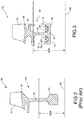
- the bore 60 has two circumferentially-extending annular rings 68 each positioned in a circumferentially-extending annular recess 70 of the bore 60, as shown.
- the annular rings 68 are formed from a different material than the body 57 of the disk 56.
- the annular rings 68 are formed from a composite material which has a higher yield strength and a lower density than the metallic material forming the body 57 of the disk 56. Consequently, the annular rings 68 effectively raise the SSR of the rotor 52/rotor disk 56 of the present disclosure relative to the SSR of the all-metallic rotor disk 42 of the prior art.
- the term "rotor disk” refers to both the metallic rotor disk 42 and the annular rings 68.
- the annular rings 68 may effectively increase the SSR of the rotor disk 56 relative to the prior art rotor disk 42 by several orders of magnitude or more.
- the increase of the SSR of the rotor disk 56 allows the bore 60 to be positioned further radially outward of the rotational axis 62 compared to the prior art rotor disk 42, while providing at least an equivalent or comparable rotor restraint.
- the web 64 and the bore 60 of the rotor disk 56 of the present disclosure may be radially shorter and formed of significantly less material than the all-metallic rotor disk of FIG. 2 . Consequently, the rotor disk 56 may be lighter in weight and may free up a significant amount of space in the gas turbine engine for the placement other components, if desired.
- the annular ring 68 extends circumferentially through the annular recess 70 of the bore 60 to strengthen the rotor 52 in the circumferential direction, as best shown in FIG. 5 .
- the composite material of the annular ring 68 includes filaments 72 embedded in a matrix 74.
- the filaments 72 are continuous filaments having a filament length to diameter ratio of 200 or more.
- the filaments 72 are non-woven and are wound circumferentially through the annular recess 70 and about the rotational axis 62, as shown in FIG. 5 .
- the composite material is an organic matrix composite (O.M.C.) and the matrix 74 is a cured organic resin matrix.
- the filaments 72 may be organic fibers such as carbon fibers, although many other types of fibers may also be used.
- the composite material is a metal matrix composite (M.M.C.) in which case the matrix 74 is a metallic matrix.
- M.M.C. metal matrix composite
- those skilled in the art will understand that other types of filaments and composite materials may be used such as, but not limited to, woven fiber fabrics, metallic wire filaments, ceramic filaments, ceramic matrix composites, and hybrid composites composed of at least three different types of materials.
- the bore 60 has an axial outer edge 76 that is the surface of the bore 60 that is the furthest radially outward of the rotational axis 62.
- the annular recess 70 is formed along the outer edge 76 and axially between the outer edge 76 and the web 64.
- the bore 60 has two annular recesses 70, with each annular recess 70 disposed on opposing sides of the web 64, as shown.
- the annular recess 70 has radially extending edges 78 that assist in retaining the annular ring 68 in the recess 70, such that the ring 68 may be retained in the recess 70 without the need for mechanical fasteners.
- the bore 60 has a shape that is axial wide enough along the outer edge 76 to provide sufficient material axially forward of or axially aft of the edges 78 to assist in retaining the annular ring 68.
- the dimensions and cross-sectional shape of the annular recess 70 is configured to accommodate a shear stress 80 and/or a bending stress 82 that may be imposed on the metallic material of the bore 60 by the annular ring 68.
- the shear stress 80 and the bending stress 82 may result, in part, from the lower thermal expansion coefficient of the composite material of the ring 68 compared to the metallic material of the bore 60.
- the ring 68 may expand to a lesser degree than the bore 60 in response to thermal and/or structural loads, thereby imposing possible stresses 80, 82 on the bore 60.
- the depth (d 1 ) of the annular recess 70 may be designed to ensure that the metallic bore material beneath the recess 70 is thick enough to withstand the shear stress 80.
- the shape of the radially extending edges 78 may be designed to ensure that the bore 60 is capable of withstanding the bending stress 82 imposed by the ring 68.
- the annular recess 70 has a semi-circular shape or a semi-elliptical shape in cross-section with the radially extending edges 78 curving toward the outer edge 76 to accommodate the bending stress 82, as shown in FIG. 4 .
- the overall shape of the bore 60 may also be designed to suitably handle shear and bending stresses applied by the ring 68.
- the bore 60 has a rectangular shape in cross-section as shown in FIGs. 3-4 .
- the bore 60 has an anchor-shape in cross-section as shown in FIG. 6 .
- FIG. 7 A series of steps which may be used to fabricate the reinforced rotor disk 56 of the present disclosure are shown in FIG. 7 .
- the rotor 52 or disk 56 is provided with one or more annular recesses formed along the outer edge 76 of the bore 60.
- the filaments 72 are then wound through each of the recesses 70 by wrapping the filaments 72 circumferentially about the rotational axis 62 to build up the filament material in each recess 70 to a desired level.
- the step 92 may be achieved by wrapping dry filaments through the recess 70, or by wrapping pre-preg layers of the filaments through the recess 70 as described above.
- an uncured resin matrix may then be injected into the recess 70 to embed the filaments 72 in the resin according to an optional step 94. In either case, the resin is then cured in place using the recess 70 as a mold to shape the annular ring 68 according to a next step 96, as shown. In some cases, an additional mold may also be used to shape a top surface 97 of the ring 68 as well.
- the structurally-reinforced disk 56 is then provided according to a next step 98.
- the structurally-reinforced rotor disk of the present disclosure may have a significantly increased SSR than comparable all-metallic rotor systems of the prior art due to the higher strength and lower density provided by the composite material.
- the increased SSR may permit the web to be shortened radially and the bore to be positioned further radially outward than comparable all-metallic rotor designs of the prior art, with minimal impacts on rotor performance.
- the smaller and lighter weight reinforced rotor disk disclosed herein may free up space in the gas turbine engine for the placement of other components such as gears or hubs, as well as lead to valuable improvements in engine fuel efficiency.
- the bore annular recess for holding the structurally-reinforcing annular ring is designed to retain the ring without the need for additional mechanical fasteners which could otherwise counteract some of the weight reduction provided by the smaller rotor disk.
- the reinforced rotor disk disclosed herein may have a reduced tendency to expand under thermal or structural load due to the lower coefficient of thermal expansion of the composite material of the annular ring. The reduced tendency to expand may improve the ability to control and maintain tight clearance between the rotor blades and abradable material radially outside of the tips of the blades, thereby minimizing leakage and providing additional improvements in engine efficiency. It is expected that the technology disclosed herein may find wide industrial applicability in a wide range of areas such as, but not limited to, aerospace technologies.
Landscapes
- Engineering & Computer Science (AREA)
- Mechanical Engineering (AREA)
- General Engineering & Computer Science (AREA)
- Chemical & Material Sciences (AREA)
- Combustion & Propulsion (AREA)
- Ceramic Engineering (AREA)
- Turbine Rotor Nozzle Sealing (AREA)
- Structures Of Non-Positive Displacement Pumps (AREA)
Claims (8)
- Strukturell verstärkte Rotorscheibe (56) für einen Gasturbinenmotor (10), umfassend:einen Körper (57), der einen Kranz (58) beinhaltet, der konfiguriert ist, um Schaufeln (54) zu stützen, wobei eine sich axial erstreckende Bohrung (60) radial innen von dem Kranz (58) angeordnet ist und wobei ein sich radial erstreckender Steg (64) den Kranz (58) und die Bohrung (60) verbindet;zwei sich in Umfangsrichtung erstreckende kreisförmige Aussparungen (70), die an gegenüberliegenden Seiten des Stegs (64) gebildet werden; undzwei kreisförmige Ringe (68), die in den zwei kreisförmigen Aussparungen (70) gehalten werden, wobei die kreisförmigen Ringe (68) aus einem sich von dem Körper (57) der Rotorscheibe (56) unterscheidenden Material gebildet sind, um einen selbsterhaltenden Radius (Self-sustaining Radius - SSR) der Rotorscheibe (56) zu erhöhen, wobei die kreisförmigen Ringe (68) aus einem Verbundwerkstoff gebildet sind, der Endlosfilamente (72) beinhaltet, die in Umfangsrichtung durch die kreisförmigen Aussparungen (70) gewickelt sind, und die Endlosfilamente (72) innerhalb einer Matrix des Verbundwerkstoffs eingebettet sind;dadurch gekennzeichnet, dass:
die Bohrung (60) im Querschnitt eine rechteckige Form oder eine Ankerform aufweist und eine axial äußere Kante (76) beinhaltet, wobei die zwei sich in Umfangsrichtung erstreckenden kreisförmigen Aussparungen (70) in der Bohrung (60) axial zwischen der äußeren Kante (76) und dem Steg (64) gebildet sind und die kreisförmigen Aussparungen (70) im Querschnitt mit den sich radial erstreckenden Kanten (78) eine halbkreisförmige oder halbelliptische Form aufweisen. - Strukturell verstärkte Rotorscheibe (56) nach Anspruch 1, wobei der Verbundwerkstoff ein organischer Matrixverbundwerkstoff ist.
- Strukturell verstärkte Rotorscheibe (56) nach Anspruch 1 oder 2, wobei die Endlosfilamente (72) Kohlestofffasern sind.
- Strukturell verstärkte Rotorscheibe (56) nach Anspruch 1, wobei der Verbundwerkstoff ein Metall-Matrix-Verbundwerkstoff ist.
- Strukturell verstärkte Rotorscheibe (56) nach einem der vorhergehenden Ansprüche, wobei der Körper (57) aus einem metallischen Werkstoff gebildet ist.
- Strukturell verstärkte Rotorscheibe (56) nach einem der vorhergehenden Ansprüche, wobei die Rotorscheibe (56) Teil eines Rotors mit integrierten Schaufeln ist.
- Gasturbinenmotor, umfassend:einen Gebläseabschnitt (12);einen Verdichterabschnitt (22) stromabwärts des Gebläseabschnitts (12);eine Brennkammer (24) stromabwärts des Verdichterabschnitts (22);einen Turbinenabschnitt (26) stromabwärts der Brennkammer (24); undeine strukturell verstärkte Rotorscheibe (56) in mindestens einem von dem Gebläseabschnitt (12), dem Verdichterabschnitt (22) und dem Turbinenabschnitt (26), wobei die Rotorscheibe eine strukturell verstärkte Rotorscheibe (56) nach einem der Ansprüche 1 bis 6 umfasst.
- Verfahren zur Herstellung einer strukturell verstärkten Rotorscheibe (56) für einen Gasturbinenmotor (10), umfassend:Bereitstellen einer Rotorscheibe (56), die einen Kranz (58), eine sich axial erstreckenden Bohrung (60), die im Querschnitt eine rechteckige Form oder Ankerform aufweist, wobei die Bohrung radial innen von dem Kranz (58) angeordnet ist, und einen sich radial erstreckenden Steg (64) beinhaltet, der den Kranz (58) und die Bohrung (60) verbindet, wobei die Bohrung (60) eine axial äußere Kante (76) und zwei sich in Umfangsrichtung erstreckende kreisförmige Aussparungen (70) beinhaltet, die auf gegenüberliegenden Seiten des Stegs (64) axial zwischen der äußeren Kante (76) und dem Steg (64) gebildet sind, wobei die kreisförmigen Aussparungen (70) im Querschnitt mit den sich radial erstreckenden Kanten (78) eine halbkreisförmige oder halbelliptische Form aufweisen;Wickeln eines oder mehr Endlosfilamente (72) in Umfangsrichtung durch die kreisförmigen Aussparungen (70) der Bohrung (60);optional, Einspritzen einer härtbaren Matrix (74) in die kreisförmigen Aussparungen (70);Aushärten der Matrix (74), um einen kreisförmigen Ring (68) in den kreisförmigen Aussparungen (70) bereitzustellen, wobei der kreisförmige Ring (68) die Rotorscheibe (56) strukturell verstärkt, wobei die Endlosfilamente (72) innerhalb der Matrix (74) eingebettet sind.
Applications Claiming Priority (1)
| Application Number | Priority Date | Filing Date | Title |
|---|---|---|---|
| US201462080811P | 2014-11-17 | 2014-11-17 |
Publications (2)
| Publication Number | Publication Date |
|---|---|
| EP3020918A1 EP3020918A1 (de) | 2016-05-18 |
| EP3020918B1 true EP3020918B1 (de) | 2018-11-14 |
Family
ID=54548088
Family Applications (1)
| Application Number | Title | Priority Date | Filing Date |
|---|---|---|---|
| EP15195023.5A Active EP3020918B1 (de) | 2014-11-17 | 2015-11-17 | Verstärkte gasturbinenmotorrotorscheibe |
Country Status (2)
| Country | Link |
|---|---|
| US (1) | US10370971B2 (de) |
| EP (1) | EP3020918B1 (de) |
Families Citing this family (5)
| Publication number | Priority date | Publication date | Assignee | Title |
|---|---|---|---|---|
| DE102016118779A1 (de) * | 2016-10-04 | 2018-04-05 | Rolls-Royce Deutschland Ltd & Co Kg | Turbofan-Triebwerk für ein ziviles Überschallflugzeug |
| EP3495612B1 (de) * | 2017-12-06 | 2021-05-12 | Ansaldo Energia IP UK Limited | Verfahren zur herstellung einer verbundkomponente |
| US10876429B2 (en) | 2019-03-21 | 2020-12-29 | Pratt & Whitney Canada Corp. | Shroud segment assembly intersegment end gaps control |
| US11268388B2 (en) * | 2020-04-17 | 2022-03-08 | Raytheon Technologies Corporation | Composite reinforced rotor |
| EP4717877A1 (de) * | 2023-12-19 | 2026-04-01 | Lilium GmbH | Beschaufelte laufscheibe für einen angetriebenen rotor eines triebwerks einer flugzeugantriebseinheit, antriebseinheit für ein flugzeug und flugzeug |
Family Cites Families (14)
| Publication number | Priority date | Publication date | Assignee | Title |
|---|---|---|---|---|
| US3610777A (en) | 1970-05-15 | 1971-10-05 | Gen Motors Corp | Composite drum rotor |
| GB1553038A (en) | 1977-04-28 | 1979-09-19 | Snecma | Drum for an axial flow compressor rotor and process for its manufacture |
| DE3037388C1 (de) * | 1980-10-03 | 1982-06-16 | Deutsche Forschungs- und Versuchsanstalt für Luft- und Raumfahrt e.V., 5300 Bonn | Bandage zur radialen Spannung der Segmente eines aus Einzelsegmenten aufgebauten Verdichterlaufrades fuer Gasturbinen |
| DE4319727C2 (de) * | 1993-06-15 | 1996-08-29 | Mtu Muenchen Gmbh | Verfahren zur Herstellung eines Schaufelringes für einen trommelartig aufgebauten Rotor, insbesondere Verdichterrotor einer Turbomaschine |
| DE4324755C1 (de) * | 1993-07-23 | 1994-09-22 | Mtu Muenchen Gmbh | Verfahren zur Herstellung faserverstärkter Triebwerkskomponenten |
| FR2755468B1 (fr) | 1996-11-07 | 1998-12-04 | Snecma | Etage de rotor de turbomachine renforce par des fibres |
| GB2456637B (en) | 1997-06-03 | 2010-01-13 | Rolls Royce Plc | A fibre reinforced metal rotor |
| US6213720B1 (en) | 1999-06-11 | 2001-04-10 | Alliedsignal, Inc. | High strength composite reinforced turbomachinery disk |
| DE10163951C1 (de) | 2001-12-22 | 2002-12-19 | Mtu Aero Engines Gmbh | Rotorscheibe aus Metall mit örtlichen Faserverstärkungen |
| DE10218459B3 (de) | 2002-04-25 | 2004-01-15 | Mtu Aero Engines Gmbh | Verdichter in mehrstufiger Axialbauart |
| DE10358421A1 (de) | 2003-12-13 | 2005-07-07 | Mtu Aero Engines Gmbh | Rotor für eine Turbomaschine |
| FR2893093B1 (fr) | 2005-11-08 | 2008-02-08 | Snecma Sa | Montage d'un anneau composite sur un disque de rotor d'une turbomachine. |
| DE102006015838A1 (de) | 2006-04-03 | 2007-10-04 | Rolls-Royce Deutschland Ltd & Co Kg | Axialkompressor für ein Gasturbinentriebwerk |
| FR2922587B1 (fr) | 2007-10-22 | 2010-02-26 | Snecma | Roue de turbomachine |
-
2015
- 2015-11-02 US US14/929,771 patent/US10370971B2/en active Active
- 2015-11-17 EP EP15195023.5A patent/EP3020918B1/de active Active
Non-Patent Citations (1)
| Title |
|---|
| None * |
Also Published As
| Publication number | Publication date |
|---|---|
| EP3020918A1 (de) | 2016-05-18 |
| US10370971B2 (en) | 2019-08-06 |
| US20160138399A1 (en) | 2016-05-19 |
Similar Documents
| Publication | Publication Date | Title |
|---|---|---|
| EP2363574B1 (de) | Rotorschaufelherstellung unter Verwendung von keramischen Matrixverbundwerkstoffen | |
| EP2613015B1 (de) | Äußere hybride Laufschaufelluftdichtung für einen Gasturbinenmotor | |
| EP3611349B1 (de) | Schaufelaussenluftdichtung aus einem keramikmatrixverbundwerkstoff | |
| EP2820251B1 (de) | Zusammengesetzter rotor und schaufelanordnungen mit integrierten schaufelblättern | |
| US10370971B2 (en) | Reinforced gas turbine engine rotor disk | |
| EP3181814B1 (de) | Faserverstärkte schaufel | |
| EP2570601B1 (de) | Rotorscheibe aus keramischem Faserverbundwerkstoff für ein Gasturbinentriebwerk und zugehörige Rotorbaugruppe | |
| EP2932052B1 (de) | Bläsergehäuse mit thermisch konformer auskleidung | |
| EP3800327B1 (de) | Axial geneigter schaufel-stirnflansch | |
| GB2427658A (en) | Organic matrix integrally bladed rotor | |
| US11220924B2 (en) | Double box composite seal assembly with insert for gas turbine engine | |
| EP2956625B1 (de) | Stressminderung für vorderkante einer verbundschaufel | |
| EP3951137A1 (de) | Effizienter propulsor mit niedrigem druckverhältnis für gasturbinenmotoren | |
| US20190186271A1 (en) | CMC Component with Flowpath Surface Ribs | |
| EP4219908B1 (de) | Doppelkastenverbunddichtungsanordnung mit faserdichteanordnung für gasturbinenmotor | |
| EP3798420B1 (de) | Doppelkastenverbunddichtungsanordnung für gasturbinenmotor, gasturbinenmotor und verfahren | |
| EP3059390B1 (de) | Schaufelanordnung für einen gasturbinenmotor, profil und herstellungsverfahren | |
| US11668317B2 (en) | Airfoil arrangement for a gas turbine engine utilizing a shape memory alloy | |
| US11674399B2 (en) | Airfoil arrangement for a gas turbine engine utilizing a shape memory alloy | |
| US11821319B2 (en) | Frangible airfoil with shape memory alloy | |
| EP2966270B1 (de) | Komponente | |
| EP3029271B1 (de) | Rotor mit schaufeln, die durch ein befestigungssystem aus gewebten fasern abgesichert sind | |
| EP3252294B1 (de) | Torusförmiger einlaufkonus-hinterflansch |
Legal Events
| Date | Code | Title | Description |
|---|---|---|---|
| PUAI | Public reference made under article 153(3) epc to a published international application that has entered the european phase |
Free format text: ORIGINAL CODE: 0009012 |
|
| AK | Designated contracting states |
Kind code of ref document: A1 Designated state(s): AL AT BE BG CH CY CZ DE DK EE ES FI FR GB GR HR HU IE IS IT LI LT LU LV MC MK MT NL NO PL PT RO RS SE SI SK SM TR |
|
| AX | Request for extension of the european patent |
Extension state: BA ME |
|
| RAP1 | Party data changed (applicant data changed or rights of an application transferred) |
Owner name: UNITED TECHNOLOGIES CORPORATION |
|
| STAA | Information on the status of an ep patent application or granted ep patent |
Free format text: STATUS: REQUEST FOR EXAMINATION WAS MADE |
|
| 17P | Request for examination filed |
Effective date: 20161116 |
|
| RBV | Designated contracting states (corrected) |
Designated state(s): AL AT BE BG CH CY CZ DE DK EE ES FI FR GB GR HR HU IE IS IT LI LT LU LV MC MK MT NL NO PL PT RO RS SE SI SK SM TR |
|
| STAA | Information on the status of an ep patent application or granted ep patent |
Free format text: STATUS: EXAMINATION IS IN PROGRESS |
|
| 17Q | First examination report despatched |
Effective date: 20170510 |
|
| REG | Reference to a national code |
Ref country code: DE Ref legal event code: R079 Ref document number: 602015019757 Country of ref document: DE Free format text: PREVIOUS MAIN CLASS: F01D0005020000 Ipc: F01D0005340000 |
|
| RIC1 | Information provided on ipc code assigned before grant |
Ipc: F01D 5/34 20060101AFI20180319BHEP Ipc: F01D 5/06 20060101ALI20180319BHEP Ipc: F02C 3/04 20060101ALI20180319BHEP Ipc: F01D 5/02 20060101ALI20180319BHEP |
|
| GRAP | Despatch of communication of intention to grant a patent |
Free format text: ORIGINAL CODE: EPIDOSNIGR1 |
|
| STAA | Information on the status of an ep patent application or granted ep patent |
Free format text: STATUS: GRANT OF PATENT IS INTENDED |
|
| GRAJ | Information related to disapproval of communication of intention to grant by the applicant or resumption of examination proceedings by the epo deleted |
Free format text: ORIGINAL CODE: EPIDOSDIGR1 |
|
| GRAP | Despatch of communication of intention to grant a patent |
Free format text: ORIGINAL CODE: EPIDOSNIGR1 |
|
| INTG | Intention to grant announced |
Effective date: 20180511 |
|
| INTG | Intention to grant announced |
Effective date: 20180522 |
|
| GRAS | Grant fee paid |
Free format text: ORIGINAL CODE: EPIDOSNIGR3 |
|
| GRAA | (expected) grant |
Free format text: ORIGINAL CODE: 0009210 |
|
| STAA | Information on the status of an ep patent application or granted ep patent |
Free format text: STATUS: THE PATENT HAS BEEN GRANTED |
|
| AK | Designated contracting states |
Kind code of ref document: B1 Designated state(s): AL AT BE BG CH CY CZ DE DK EE ES FI FR GB GR HR HU IE IS IT LI LT LU LV MC MK MT NL NO PL PT RO RS SE SI SK SM TR |
|
| REG | Reference to a national code |
Ref country code: CH Ref legal event code: EP Ref country code: AT Ref legal event code: REF Ref document number: 1065065 Country of ref document: AT Kind code of ref document: T Effective date: 20181115 |
|
| REG | Reference to a national code |
Ref country code: DE Ref legal event code: R096 Ref document number: 602015019757 Country of ref document: DE |
|
| REG | Reference to a national code |
Ref country code: IE Ref legal event code: FG4D |
|
| REG | Reference to a national code |
Ref country code: NL Ref legal event code: MP Effective date: 20181114 |
|
| REG | Reference to a national code |
Ref country code: LT Ref legal event code: MG4D |
|
| REG | Reference to a national code |
Ref country code: AT Ref legal event code: MK05 Ref document number: 1065065 Country of ref document: AT Kind code of ref document: T Effective date: 20181114 |
|
| PG25 | Lapsed in a contracting state [announced via postgrant information from national office to epo] |
Ref country code: FI Free format text: LAPSE BECAUSE OF FAILURE TO SUBMIT A TRANSLATION OF THE DESCRIPTION OR TO PAY THE FEE WITHIN THE PRESCRIBED TIME-LIMIT Effective date: 20181114 Ref country code: BG Free format text: LAPSE BECAUSE OF FAILURE TO SUBMIT A TRANSLATION OF THE DESCRIPTION OR TO PAY THE FEE WITHIN THE PRESCRIBED TIME-LIMIT Effective date: 20190214 Ref country code: NO Free format text: LAPSE BECAUSE OF FAILURE TO SUBMIT A TRANSLATION OF THE DESCRIPTION OR TO PAY THE FEE WITHIN THE PRESCRIBED TIME-LIMIT Effective date: 20190214 Ref country code: LT Free format text: LAPSE BECAUSE OF FAILURE TO SUBMIT A TRANSLATION OF THE DESCRIPTION OR TO PAY THE FEE WITHIN THE PRESCRIBED TIME-LIMIT Effective date: 20181114 Ref country code: IS Free format text: LAPSE BECAUSE OF FAILURE TO SUBMIT A TRANSLATION OF THE DESCRIPTION OR TO PAY THE FEE WITHIN THE PRESCRIBED TIME-LIMIT Effective date: 20190314 Ref country code: ES Free format text: LAPSE BECAUSE OF FAILURE TO SUBMIT A TRANSLATION OF THE DESCRIPTION OR TO PAY THE FEE WITHIN THE PRESCRIBED TIME-LIMIT Effective date: 20181114 Ref country code: AT Free format text: LAPSE BECAUSE OF FAILURE TO SUBMIT A TRANSLATION OF THE DESCRIPTION OR TO PAY THE FEE WITHIN THE PRESCRIBED TIME-LIMIT Effective date: 20181114 Ref country code: HR Free format text: LAPSE BECAUSE OF FAILURE TO SUBMIT A TRANSLATION OF THE DESCRIPTION OR TO PAY THE FEE WITHIN THE PRESCRIBED TIME-LIMIT Effective date: 20181114 Ref country code: LV Free format text: LAPSE BECAUSE OF FAILURE TO SUBMIT A TRANSLATION OF THE DESCRIPTION OR TO PAY THE FEE WITHIN THE PRESCRIBED TIME-LIMIT Effective date: 20181114 |
|
| PG25 | Lapsed in a contracting state [announced via postgrant information from national office to epo] |
Ref country code: SE Free format text: LAPSE BECAUSE OF FAILURE TO SUBMIT A TRANSLATION OF THE DESCRIPTION OR TO PAY THE FEE WITHIN THE PRESCRIBED TIME-LIMIT Effective date: 20181114 Ref country code: AL Free format text: LAPSE BECAUSE OF FAILURE TO SUBMIT A TRANSLATION OF THE DESCRIPTION OR TO PAY THE FEE WITHIN THE PRESCRIBED TIME-LIMIT Effective date: 20181114 Ref country code: RS Free format text: LAPSE BECAUSE OF FAILURE TO SUBMIT A TRANSLATION OF THE DESCRIPTION OR TO PAY THE FEE WITHIN THE PRESCRIBED TIME-LIMIT Effective date: 20181114 Ref country code: GR Free format text: LAPSE BECAUSE OF FAILURE TO SUBMIT A TRANSLATION OF THE DESCRIPTION OR TO PAY THE FEE WITHIN THE PRESCRIBED TIME-LIMIT Effective date: 20190215 Ref country code: NL Free format text: LAPSE BECAUSE OF FAILURE TO SUBMIT A TRANSLATION OF THE DESCRIPTION OR TO PAY THE FEE WITHIN THE PRESCRIBED TIME-LIMIT Effective date: 20181114 Ref country code: PT Free format text: LAPSE BECAUSE OF FAILURE TO SUBMIT A TRANSLATION OF THE DESCRIPTION OR TO PAY THE FEE WITHIN THE PRESCRIBED TIME-LIMIT Effective date: 20190314 |
|
| REG | Reference to a national code |
Ref country code: CH Ref legal event code: PL |
|
| PG25 | Lapsed in a contracting state [announced via postgrant information from national office to epo] |
Ref country code: LU Free format text: LAPSE BECAUSE OF NON-PAYMENT OF DUE FEES Effective date: 20181117 Ref country code: IT Free format text: LAPSE BECAUSE OF FAILURE TO SUBMIT A TRANSLATION OF THE DESCRIPTION OR TO PAY THE FEE WITHIN THE PRESCRIBED TIME-LIMIT Effective date: 20181114 Ref country code: DK Free format text: LAPSE BECAUSE OF FAILURE TO SUBMIT A TRANSLATION OF THE DESCRIPTION OR TO PAY THE FEE WITHIN THE PRESCRIBED TIME-LIMIT Effective date: 20181114 Ref country code: PL Free format text: LAPSE BECAUSE OF FAILURE TO SUBMIT A TRANSLATION OF THE DESCRIPTION OR TO PAY THE FEE WITHIN THE PRESCRIBED TIME-LIMIT Effective date: 20181114 Ref country code: CZ Free format text: LAPSE BECAUSE OF FAILURE TO SUBMIT A TRANSLATION OF THE DESCRIPTION OR TO PAY THE FEE WITHIN THE PRESCRIBED TIME-LIMIT Effective date: 20181114 |
|
| REG | Reference to a national code |
Ref country code: DE Ref legal event code: R097 Ref document number: 602015019757 Country of ref document: DE |
|
| REG | Reference to a national code |
Ref country code: BE Ref legal event code: MM Effective date: 20181130 |
|
| REG | Reference to a national code |
Ref country code: IE Ref legal event code: MM4A |
|
| PG25 | Lapsed in a contracting state [announced via postgrant information from national office to epo] |
Ref country code: SM Free format text: LAPSE BECAUSE OF FAILURE TO SUBMIT A TRANSLATION OF THE DESCRIPTION OR TO PAY THE FEE WITHIN THE PRESCRIBED TIME-LIMIT Effective date: 20181114 Ref country code: EE Free format text: LAPSE BECAUSE OF FAILURE TO SUBMIT A TRANSLATION OF THE DESCRIPTION OR TO PAY THE FEE WITHIN THE PRESCRIBED TIME-LIMIT Effective date: 20181114 Ref country code: RO Free format text: LAPSE BECAUSE OF FAILURE TO SUBMIT A TRANSLATION OF THE DESCRIPTION OR TO PAY THE FEE WITHIN THE PRESCRIBED TIME-LIMIT Effective date: 20181114 Ref country code: SK Free format text: LAPSE BECAUSE OF FAILURE TO SUBMIT A TRANSLATION OF THE DESCRIPTION OR TO PAY THE FEE WITHIN THE PRESCRIBED TIME-LIMIT Effective date: 20181114 Ref country code: CH Free format text: LAPSE BECAUSE OF NON-PAYMENT OF DUE FEES Effective date: 20181130 Ref country code: MC Free format text: LAPSE BECAUSE OF FAILURE TO SUBMIT A TRANSLATION OF THE DESCRIPTION OR TO PAY THE FEE WITHIN THE PRESCRIBED TIME-LIMIT Effective date: 20181114 Ref country code: LI Free format text: LAPSE BECAUSE OF NON-PAYMENT OF DUE FEES Effective date: 20181130 |
|
| PLBE | No opposition filed within time limit |
Free format text: ORIGINAL CODE: 0009261 |
|
| STAA | Information on the status of an ep patent application or granted ep patent |
Free format text: STATUS: NO OPPOSITION FILED WITHIN TIME LIMIT |
|
| 26N | No opposition filed |
Effective date: 20190815 |
|
| PG25 | Lapsed in a contracting state [announced via postgrant information from national office to epo] |
Ref country code: IE Free format text: LAPSE BECAUSE OF NON-PAYMENT OF DUE FEES Effective date: 20181117 Ref country code: SI Free format text: LAPSE BECAUSE OF FAILURE TO SUBMIT A TRANSLATION OF THE DESCRIPTION OR TO PAY THE FEE WITHIN THE PRESCRIBED TIME-LIMIT Effective date: 20181114 |
|
| PG25 | Lapsed in a contracting state [announced via postgrant information from national office to epo] |
Ref country code: BE Free format text: LAPSE BECAUSE OF NON-PAYMENT OF DUE FEES Effective date: 20181130 |
|
| PG25 | Lapsed in a contracting state [announced via postgrant information from national office to epo] |
Ref country code: MT Free format text: LAPSE BECAUSE OF NON-PAYMENT OF DUE FEES Effective date: 20181117 |
|
| PG25 | Lapsed in a contracting state [announced via postgrant information from national office to epo] |
Ref country code: TR Free format text: LAPSE BECAUSE OF FAILURE TO SUBMIT A TRANSLATION OF THE DESCRIPTION OR TO PAY THE FEE WITHIN THE PRESCRIBED TIME-LIMIT Effective date: 20181114 |
|
| PG25 | Lapsed in a contracting state [announced via postgrant information from national office to epo] |
Ref country code: MK Free format text: LAPSE BECAUSE OF NON-PAYMENT OF DUE FEES Effective date: 20181114 Ref country code: HU Free format text: LAPSE BECAUSE OF FAILURE TO SUBMIT A TRANSLATION OF THE DESCRIPTION OR TO PAY THE FEE WITHIN THE PRESCRIBED TIME-LIMIT; INVALID AB INITIO Effective date: 20151117 Ref country code: CY Free format text: LAPSE BECAUSE OF FAILURE TO SUBMIT A TRANSLATION OF THE DESCRIPTION OR TO PAY THE FEE WITHIN THE PRESCRIBED TIME-LIMIT Effective date: 20181114 |
|
| REG | Reference to a national code |
Ref country code: DE Ref legal event code: R081 Ref document number: 602015019757 Country of ref document: DE Owner name: RAYTHEON TECHNOLOGIES CORPORATION (N.D.GES.D.S, US Free format text: FORMER OWNER: UNITED TECHNOLOGIES CORP., FARMINGTON, CONN., US Ref country code: DE Ref legal event code: R081 Ref document number: 602015019757 Country of ref document: DE Owner name: RTX CORPORATION (N.D.GES.D. STAATES DELAWARE),, US Free format text: FORMER OWNER: UNITED TECHNOLOGIES CORP., FARMINGTON, CONN., US |
|
| P01 | Opt-out of the competence of the unified patent court (upc) registered |
Effective date: 20230520 |
|
| REG | Reference to a national code |
Ref country code: DE Ref legal event code: R081 Ref document number: 602015019757 Country of ref document: DE Owner name: RTX CORPORATION (N.D.GES.D. STAATES DELAWARE),, US Free format text: FORMER OWNER: RAYTHEON TECHNOLOGIES CORPORATION (N.D.GES.D.STAATES DELAWARE), ARLINGTON, VA, US |
|
| PGFP | Annual fee paid to national office [announced via postgrant information from national office to epo] |
Ref country code: DE Payment date: 20251022 Year of fee payment: 11 |
|
| PGFP | Annual fee paid to national office [announced via postgrant information from national office to epo] |
Ref country code: GB Payment date: 20251022 Year of fee payment: 11 |
|
| PGFP | Annual fee paid to national office [announced via postgrant information from national office to epo] |
Ref country code: FR Payment date: 20251022 Year of fee payment: 11 |