EP3020922B1 - Système de pale de turbomachine avec élément amorti - Google Patents
Système de pale de turbomachine avec élément amorti Download PDFInfo
- Publication number
- EP3020922B1 EP3020922B1 EP15190023.0A EP15190023A EP3020922B1 EP 3020922 B1 EP3020922 B1 EP 3020922B1 EP 15190023 A EP15190023 A EP 15190023A EP 3020922 B1 EP3020922 B1 EP 3020922B1
- Authority
- EP
- European Patent Office
- Prior art keywords
- guide housing
- recess
- locking plate
- tuning element
- element guide
- Prior art date
- Legal status (The legal status is an assumption and is not a legal conclusion. Google has not performed a legal analysis and makes no representation as to the accuracy of the status listed.)
- Active
Links
- 238000003780 insertion Methods 0.000 claims description 33
- 230000037431 insertion Effects 0.000 claims description 33
- 238000003466 welding Methods 0.000 claims description 6
- 238000004519 manufacturing process Methods 0.000 claims description 3
- 238000000034 method Methods 0.000 claims description 2
- 239000011800 void material Substances 0.000 description 9
- 238000011161 development Methods 0.000 description 6
- 230000018109 developmental process Effects 0.000 description 6
- 238000005452 bending Methods 0.000 description 4
- 238000013461 design Methods 0.000 description 4
- 239000000463 material Substances 0.000 description 3
- 230000001755 vocal effect Effects 0.000 description 3
- 230000001419 dependent effect Effects 0.000 description 2
- 238000005476 soldering Methods 0.000 description 2
- 238000004026 adhesive bonding Methods 0.000 description 1
- 238000010276 construction Methods 0.000 description 1
- 230000000694 effects Effects 0.000 description 1
- 238000005516 engineering process Methods 0.000 description 1
- 229910000856 hastalloy Inorganic materials 0.000 description 1
- 238000012986 modification Methods 0.000 description 1
- 230000004048 modification Effects 0.000 description 1
Images


Classifications
-
- F—MECHANICAL ENGINEERING; LIGHTING; HEATING; WEAPONS; BLASTING
- F01—MACHINES OR ENGINES IN GENERAL; ENGINE PLANTS IN GENERAL; STEAM ENGINES
- F01D—NON-POSITIVE DISPLACEMENT MACHINES OR ENGINES, e.g. STEAM TURBINES
- F01D5/00—Blades; Blade-carrying members; Heating, heat-insulating, cooling or antivibration means on the blades or the members
- F01D5/12—Blades
- F01D5/14—Form or construction
-
- F—MECHANICAL ENGINEERING; LIGHTING; HEATING; WEAPONS; BLASTING
- F01—MACHINES OR ENGINES IN GENERAL; ENGINE PLANTS IN GENERAL; STEAM ENGINES
- F01D—NON-POSITIVE DISPLACEMENT MACHINES OR ENGINES, e.g. STEAM TURBINES
- F01D5/00—Blades; Blade-carrying members; Heating, heat-insulating, cooling or antivibration means on the blades or the members
- F01D5/12—Blades
- F01D5/14—Form or construction
- F01D5/16—Form or construction for counteracting blade vibration
-
- F—MECHANICAL ENGINEERING; LIGHTING; HEATING; WEAPONS; BLASTING
- F01—MACHINES OR ENGINES IN GENERAL; ENGINE PLANTS IN GENERAL; STEAM ENGINES
- F01D—NON-POSITIVE DISPLACEMENT MACHINES OR ENGINES, e.g. STEAM TURBINES
- F01D5/00—Blades; Blade-carrying members; Heating, heat-insulating, cooling or antivibration means on the blades or the members
- F01D5/12—Blades
- F01D5/26—Antivibration means not restricted to blade form or construction or to blade-to-blade connections or to the use of particular materials
-
- F—MECHANICAL ENGINEERING; LIGHTING; HEATING; WEAPONS; BLASTING
- F01—MACHINES OR ENGINES IN GENERAL; ENGINE PLANTS IN GENERAL; STEAM ENGINES
- F01D—NON-POSITIVE DISPLACEMENT MACHINES OR ENGINES, e.g. STEAM TURBINES
- F01D9/00—Stators
- F01D9/02—Nozzles; Nozzle boxes; Stator blades; Guide conduits, e.g. individual nozzles
- F01D9/04—Nozzles; Nozzle boxes; Stator blades; Guide conduits, e.g. individual nozzles forming ring or sector
- F01D9/041—Nozzles; Nozzle boxes; Stator blades; Guide conduits, e.g. individual nozzles forming ring or sector using blades
-
- F—MECHANICAL ENGINEERING; LIGHTING; HEATING; WEAPONS; BLASTING
- F04—POSITIVE - DISPLACEMENT MACHINES FOR LIQUIDS; PUMPS FOR LIQUIDS OR ELASTIC FLUIDS
- F04D—NON-POSITIVE-DISPLACEMENT PUMPS
- F04D29/00—Details, component parts, or accessories
- F04D29/08—Sealings
- F04D29/083—Sealings especially adapted for elastic fluid pumps
-
- F—MECHANICAL ENGINEERING; LIGHTING; HEATING; WEAPONS; BLASTING
- F04—POSITIVE - DISPLACEMENT MACHINES FOR LIQUIDS; PUMPS FOR LIQUIDS OR ELASTIC FLUIDS
- F04D—NON-POSITIVE-DISPLACEMENT PUMPS
- F04D29/00—Details, component parts, or accessories
- F04D29/66—Combating cavitation, whirls, noise, vibration or the like; Balancing
- F04D29/661—Combating cavitation, whirls, noise, vibration or the like; Balancing especially adapted for elastic fluid pumps
- F04D29/666—Combating cavitation, whirls, noise, vibration or the like; Balancing especially adapted for elastic fluid pumps by means of rotor construction or layout, e.g. unequal distribution of blades or vanes
-
- F—MECHANICAL ENGINEERING; LIGHTING; HEATING; WEAPONS; BLASTING
- F16—ENGINEERING ELEMENTS AND UNITS; GENERAL MEASURES FOR PRODUCING AND MAINTAINING EFFECTIVE FUNCTIONING OF MACHINES OR INSTALLATIONS; THERMAL INSULATION IN GENERAL
- F16F—SPRINGS; SHOCK-ABSORBERS; MEANS FOR DAMPING VIBRATION
- F16F15/00—Suppression of vibrations in systems; Means or arrangements for avoiding or reducing out-of-balance forces, e.g. due to motion
- F16F15/32—Correcting- or balancing-weights or equivalent means for balancing rotating bodies, e.g. vehicle wheels
-
- F—MECHANICAL ENGINEERING; LIGHTING; HEATING; WEAPONS; BLASTING
- F05—INDEXING SCHEMES RELATING TO ENGINES OR PUMPS IN VARIOUS SUBCLASSES OF CLASSES F01-F04
- F05D—INDEXING SCHEME FOR ASPECTS RELATING TO NON-POSITIVE-DISPLACEMENT MACHINES OR ENGINES, GAS-TURBINES OR JET-PROPULSION PLANTS
- F05D2230/00—Manufacture
- F05D2230/20—Manufacture essentially without removing material
- F05D2230/23—Manufacture essentially without removing material by permanently joining parts together
- F05D2230/232—Manufacture essentially without removing material by permanently joining parts together by welding
-
- F—MECHANICAL ENGINEERING; LIGHTING; HEATING; WEAPONS; BLASTING
- F05—INDEXING SCHEMES RELATING TO ENGINES OR PUMPS IN VARIOUS SUBCLASSES OF CLASSES F01-F04
- F05D—INDEXING SCHEME FOR ASPECTS RELATING TO NON-POSITIVE-DISPLACEMENT MACHINES OR ENGINES, GAS-TURBINES OR JET-PROPULSION PLANTS
- F05D2230/00—Manufacture
- F05D2230/20—Manufacture essentially without removing material
- F05D2230/23—Manufacture essentially without removing material by permanently joining parts together
- F05D2230/232—Manufacture essentially without removing material by permanently joining parts together by welding
- F05D2230/237—Brazing
-
- F—MECHANICAL ENGINEERING; LIGHTING; HEATING; WEAPONS; BLASTING
- F05—INDEXING SCHEMES RELATING TO ENGINES OR PUMPS IN VARIOUS SUBCLASSES OF CLASSES F01-F04
- F05D—INDEXING SCHEME FOR ASPECTS RELATING TO NON-POSITIVE-DISPLACEMENT MACHINES OR ENGINES, GAS-TURBINES OR JET-PROPULSION PLANTS
- F05D2250/00—Geometry
- F05D2250/20—Three-dimensional
- F05D2250/24—Three-dimensional ellipsoidal
- F05D2250/241—Three-dimensional ellipsoidal spherical
-
- F—MECHANICAL ENGINEERING; LIGHTING; HEATING; WEAPONS; BLASTING
- F05—INDEXING SCHEMES RELATING TO ENGINES OR PUMPS IN VARIOUS SUBCLASSES OF CLASSES F01-F04
- F05D—INDEXING SCHEME FOR ASPECTS RELATING TO NON-POSITIVE-DISPLACEMENT MACHINES OR ENGINES, GAS-TURBINES OR JET-PROPULSION PLANTS
- F05D2260/00—Function
- F05D2260/30—Retaining components in desired mutual position
-
- F—MECHANICAL ENGINEERING; LIGHTING; HEATING; WEAPONS; BLASTING
- F05—INDEXING SCHEMES RELATING TO ENGINES OR PUMPS IN VARIOUS SUBCLASSES OF CLASSES F01-F04
- F05D—INDEXING SCHEME FOR ASPECTS RELATING TO NON-POSITIVE-DISPLACEMENT MACHINES OR ENGINES, GAS-TURBINES OR JET-PROPULSION PLANTS
- F05D2260/00—Function
- F05D2260/96—Preventing, counteracting or reducing vibration or noise
-
- F—MECHANICAL ENGINEERING; LIGHTING; HEATING; WEAPONS; BLASTING
- F05—INDEXING SCHEMES RELATING TO ENGINES OR PUMPS IN VARIOUS SUBCLASSES OF CLASSES F01-F04
- F05D—INDEXING SCHEME FOR ASPECTS RELATING TO NON-POSITIVE-DISPLACEMENT MACHINES OR ENGINES, GAS-TURBINES OR JET-PROPULSION PLANTS
- F05D2260/00—Function
- F05D2260/96—Preventing, counteracting or reducing vibration or noise
- F05D2260/961—Preventing, counteracting or reducing vibration or noise by mistuning rotor blades or stator vanes with irregular interblade spacing, airfoil shape
Definitions
- the work leading to this invention has been funded under the Seventh Framework Program of the European Union (FP7 / 2007-2013) for the Clean Sky Joint Technology Initiative under Grant Agreement No. CSJU-GAM-SAGE-2008-001.
- the present invention relates to a turbomachine blade assembly, a turbomachine, in particular a gas turbine, with a turbomachine blade assembly and a method of manufacturing a turbomachine blade assembly.
- a turbomachine blade assembly having a turbomachinery blade and a multi-part void guide housing having a cavity in which a void body provided for butting contact with the void lead housing is received, wherein the void lead housing is disposed in a recess of the turbomachine blade.
- An object of an embodiment of the present invention is to improve a turbomachine. This object is achieved by a turbomachine blade arrangement having the features of claim 1.
- Claims 3, 4 provide protection for a turbomachine having a turbomachine blade assembly described herein or a method of making a turbomachine blade assembly described herein.
- Advantageous embodiments of the invention are the subject of the dependent claims.
- a turbomachinery vane assembly includes a turbomachinery blade and one or more void guide housings each having one or more cavities in each of which one or more vane bodies provided for abutting contact with the voxel guide housing are received, the void body guide housing (s) each being a recess of the turbomachinery blade arranged are, in particular in each case completely or entirely within the turbomachinery blade.
- the turbomachine blade may be a rotor or vane of a turbomachine, in particular a gas turbine, in particular an aircraft engine gas turbine and / or a compressor or turbine stage of the gas turbine.
- One or more of the tuning body guide housing or the recesses may be arranged in each case, preferably completely, in a radially inner or radially outer shroud, in particular a blade root, or an airfoil of the turbomachine blade.
- At least one cavity of at least one voice body guide housing, in which at least one voice element is accommodated is gas-tightly closed, in a development several, in particular all cavities of one or more voice body guide housing of the turbomachine blade arrangement.
- the voice element and its guides can advantageously be protected from a working gas of the turbomachine, in particular an air stream of a compressor stage or an exhaust gas stream of a turbine stage, and thus improve its effect and / or lifetime.
- a tuning body guide housing has two or more parts, in particular a base body and a lid, which are or are welded together and together define one or more of the gas-tight cavities, in particular all gas-tight cavities of the voice body guide housing.
- a Greater life of the voice guide housing, in particular the gas-tightness achieved become.
- one or more parts of the tuning body guide housing are Haynes 230, Hastelloy X, or the like.
- one or more of the voice body guide housings are integrally connected, in particular soldered, to the turbomachine blade.
- the voice body guide housing in turn can not be (permanently) gas-tight in the recess of the turbomachine blade or be, in particular by soldering, which is advantageous especially in non-or poorly weldable turbomachinery material can be.
- one or more of the vocal body guide housings are fastened by a locking plate in the respective recess, in particular with positive and / or frictional engagement. This may be particularly useful when a design life of the turbomachinery blade is above a design life of the tuning body guide housing and this is therefore one or more times to be replaced. Accordingly, or in one embodiment, the or the tuning body guide housing are fixed without material connection with the respective recess in this.
- a voice guide housing is secured by a locking plate in a recess by first sequentially or successively inserted the Stimm emotions involvedsgeophuse and then or previously the locking plate through an insertion of the recess in the recess and in a development then the Stimm stresses involvedsgeophuse and the Locking plate can be connected to each other in the recess, wherein the insertion, in particular its contour is designed such that it allows the sequential insertion of the voice body guide housing and the locking plate, but positively prevents execution of the locking plate together with, in particular connected to this, the voice guide housing.
- the voice body guide housing and the locking plate in the recess are connected together to form a structural unit, the outer dimension of which is greater than the insertion opening, so that this is an execution of the assembly positively prevented and thus fixed voice housing guide housing and locking plate in the recess or fixed with or without movement play.
- the locking plate can be inserted after the voice body guide housing in the recess and in this, in particular frictionally or positively, be attached or be.
- a tuning body guide housing can be secured by a locking plate in a recess or be by the locking plate in the recess frictionally and / or positively, in particular by one or more bent tabs of the locking plate, attached and locking plate and Stimm stresses Entitiesgephaseuse in advance, this or subsequently connected together be or are.
- the locking plate is on the one hand connected to the tuning body guide housing and on the other hand fixed in the recess with or without movement play.
- the safety plate is or is secured against rotation in the recess, in particular by the bent tab (s).
- the tuning body guide housing in particular together with the tuning body guide housing or in advance, be introduced by a rotational movement in the recess and then fixed in this or fixed with or without movement play.
- the locking plate for this purpose at least partially on a circular contour in order to facilitate the rotational movement, in particular to guide positively.
- a locking plate is positively connected to a voice body guide housing, in particular by one or more bent tabs of the locking plate.
- the locking plate is or frictionally engaged with the voice body guide housing, in particular by one or more bent tabs of the locking plate connected.
- a locking plate is integrally connected to a Stimm emotions enclosuresgebliuse, in particular soldered or welded.
- this material connection can be separated in one embodiment, in particular, when together securely connected to a unit locking washer and voice housing guide housing can not be performed together from an insertion of the recess.
- connected to a unit locking plate and voice guide housing can also be removed as a unit from the recess by, for example, by bending back one or more bent tabs of the locking plate whose attachment is released in the recess.
- the locking plate is elastically deformed in the recess and / or frictionally clamped against the recess by the voice body guide housing connected to it.
- two legs of a U-shaped locking plate are elastically spread in the recess by the tuning body guide housing inserted in its groove between the legs.
- one or more voice bodies in each case individually or alone, arranged in a cavity of a voice body guide housing, this, in particular by welding two or more parts of the voice body guide housing, gas-tight, and the vocal body guide housing, in particular subsequently, in a recess of the turbomachinery blade arranged.
- Fig. 1B 1 is a sectional view of a portion of a turbomachine blade assembly of a turbomachine according to an embodiment of the present invention having a turbomachinery blade 10 and a two-part, multi-cavity, void guide housing 21, 22, each receiving a single void body 3 provided for abutting contact with the void guide housing ,
- the voice body guide housing has a base body 21 and a lid 22, which are welded together and together define the cavities, which are thereby sealed gas-tight.
- the voice body guide housing 21, 22 is or is completely disposed in a recess 12 of the turbomachine blade and fixed therein by a locking plate 40 positively with movement play.
- Fig. 1A indicated that the voice body guide housing 21, 22 inserted through an insertion opening 13 of the recess 12 in this.
- the locking plate 40 is inserted through the insertion opening 13 and connected to the voice body guide housing 21, 22 by welding cohesively to form a unit, as in Fig. 1B indicated by a weld.
- the insertion opening 13 is formed, in particular dimensioned, that it allows this sequential insertion of the voice body guide housing 21, 22 and the locking plate 40, but positively prevents execution of the locking plate together with the welded thereto voids body housing, as an outer dimension of each other to a Assembly connected voice body guide housing 21, 22 and locking plate 40 is greater than the insertion 13th
- Fig. 2A shows a turbomachine blade assembly of a turbomachine according to another embodiment of the present invention in a plan view of an insertion opening 13, Fig. 2B a section along the line BB in Fig. 2A , Corresponding features are identified by identical reference numerals, so that reference is made to the remainder of the description and will be discussed below only differences.
- Fig. 2 In the execution of Fig. 2 are the Stimm emotions unitsgekoruse 21, 22 and the locking plate 40 positively connected to form a unit by a tab 41 of the locking plate 40 is bent after the sequential insertion of locking plate 40 and then Stimm stresses Operationssgephaseuse 21, 22 through the insertion opening 13 into the recess 12 ,
- the insertion opening 13 has projections or stops 14, which form-fit the assembly of mutually positively connected to form a unit voice body guide housing 21, 22 and locking plate 40 with movement play in the recess 12.
- the tab 41 can be bent back and then first the voice body guide housing 21, 22 and then the locking plate 40 are removed from the recess 12.
- Fig. 3A shows in Fig. 2A
- a turbomachine blade assembly of a turbomachine according to another embodiment of the present invention in a plan view of an insertion opening 13, Fig. 3B in Fig. 2B corresponding manner a section along the line BB in Fig. 3A
- Corresponding features are again identified by identical reference numerals, so that reference is made to the rest of the description and will be discussed below only differences.
- voice body guide housing 21, 22 and locking plate 40 are welded or pre-welded together. Additionally or alternatively, the voice body guide housing 21, 22 and locking plate 40 are positively connected to each other by a bent tab 41 of the locking plate 40.
- the assembly of locking plate 40 and the tuning body guide housing 21, 22 can be removed from the recess 12 by 40 its attachment in the recess 12 is released by bending back the tab 42 of the locking plate.
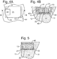
- Fig. 4A shows in Fig. 2A, 3A
- a turbomachine blade assembly of a turbomachine according to another embodiment of the present invention in a plan view of an insertion opening 13, Fig. 4B in Fig. 2B, 3B corresponding manner a section along the line BB in Fig. 4A
- Corresponding features are again identified by identical reference numerals, so that reference is made to the rest of the description and will be discussed below only differences.
- Fig. 4 In the execution of Fig. 4 are two legs 43, 44 of the U-shaped locking plate 40 by the advantageous wedge-shaped and introduced into the defined by the legs 43, 44 groove tuning body guide housing 21, 22 in the recess 12 elastically spreads. As a result, they are on the one hand clamped frictionally against the recess. On the other hand, they thus engage behind the insertion opening 13, so that the securing plate 40, which is spread by the voice guide housing 21, 22 connected to it, is also fixed in a form-fitting manner in the recess 12, since its insertion opening carries out the securing plate 40 together with the latter connected voice body guide housing 21, 22 positively prevented.
- Fig. 5 shows a section through a turbomachine blade assembly of a turbomachine according to another embodiment of the present invention. Corresponding features are again identified by identical reference numerals, so that reference is made to the rest of the description and will be discussed below only differences.
- the voice body guide housing 21, 22 is inserted through the insertion opening 13 in the recess 12 and lowered in this.
- the locking plate 40 is inserted through the insertion opening 13 in the recess 12 and in this frictionally and / or positively, for example by one or more bent tabs (not shown) attached.
- Figs. 6A-6F show sections through a turbomachine blade assembly of a turbomachine according to a further embodiment, which facilitates the understanding of the invention, but is not part of the invention. Corresponding features are again identified by identical reference numerals, so that reference is made to the rest of the description and will be discussed below only differences. In the execution of Fig.
- the voice body guide housing 21, 22 is received in a recess 12 in an inner shroud of the turbomachine blade 10 and secured by a locking plate 40 positively.
- a locking plate 40 positively.
- tabs 41 of the locking plate 40 are introduced by bending into undercuts of the recess 12 and secured there form-fitting manner, in particular from the sequence of figures Fig. 6E ⁇ Fig. 6D and the cuts Fig. 6D, Fig. 6F recognizable.
Landscapes
- Engineering & Computer Science (AREA)
- General Engineering & Computer Science (AREA)
- Mechanical Engineering (AREA)
- Physics & Mathematics (AREA)
- Acoustics & Sound (AREA)
- Aviation & Aerospace Engineering (AREA)
- Structures Of Non-Positive Displacement Pumps (AREA)
- Turbine Rotor Nozzle Sealing (AREA)
Claims (5)
- Système de pale de turbomachine avec une pale de turbomachine (10) et au moins un carter de conduite d'élément amorti (21, 22) avec au moins une cavité (11) dans laquelle au moins un élément amorti (3) prévu pour le contact par impact avec le carter de conduite d'élément amorti est incorporé, dans lequel le carter de conduite d'élément amorti est disposé dans une encoche (12) de la pale de turbomachine,
dans lequel la cavité (11) du carter de conduite d'élément amorti (21, 22) dans lequel l'élément amorti (3) est incorporé est obturée de manière à être étanche au gaz, caractérisé en ce que le carter de conduite d'élément amorti présente au moins deux parties (21, 22) qui sont soudées entre elles et définissent la cavité (11) obturée de manière à être étanche au gaz,
caractérisé en outre par une plaque de verrouillage (40) à travers laquelle le carter de conduite d'élément amorti (21, 22) est fixé dans l'encoche (12),
dans lequel la plaque de verrouillage (40) est reliée avec le carter de conduite d'élément amorti (21, 22) par liaison de forme, en particulier par au moins une languette recourbée (41), ou par liaison par friction, ou par liaison de matière, en particulier brasée ou soudée, dans lequel l'encoche (12) présente une ouverture d'introduction (13) qui permet une introduction séquentielle du carter de conduite d'élément amorti (21, 22) et de la plaque de verrouillage (40) et empêche par liaison de forme une sortie de la plaque de verrouillage avec le carter de conduite d'élément amorti relié avec celui-ci. - Système de pale de turbomachine selon la revendication 1, caractérisé en ce que la plaque de verrouillage (40) est déformée élastiquement par le carter de conduite d'élément amorti (21, 22) relié avec celui-ci et/ou est tendue par liaison par friction contre l'encoche (12).
- Turbomachine, en particulier turbine à gaz, avec au moins un système de pale de turbomachine selon l'une des revendications précédentes.
- Procédé de production d'un système de pale de turbomachine, dans lequel un système de pale de turbomachine est produit selon l'une des revendications précédentes, en ce que l'au moins un élément amorti (3) est disposé dans la cavité (11) de l'au moins un carter de conduite d'élément amorti (21, 22), que la cavité (11) est obturée de manière à être étanche au gaz par soudure des au moins deux parties (21, 22) du carter de conduite d'élément amorti, et que le carter de conduite d'élément amorti est disposé dans l'encoche (12) de la pale de turbomachine,
dans lequel la plaque de verrouillage (40) est introduite par une ouverture d'introduction (13) de l'encoche (12) et fixée dans l'encoche par liaison par friction, de forme ou de matière avec le carter de conduite d'élément amorti (21, 22). - Procédé selon la revendication précédente, caractérisé en ce que la plaque de verrouillage (40) est disposée dans l'encoche (12) et fixée dans celle-ci par liaison de forme et/ou par friction, en particulier par recourbement d'une languette (42).
Applications Claiming Priority (1)
| Application Number | Priority Date | Filing Date | Title |
|---|---|---|---|
| DE102014223231.7A DE102014223231B4 (de) | 2014-11-13 | 2014-11-13 | Turbomaschinenschaufelanordnung |
Publications (2)
| Publication Number | Publication Date |
|---|---|
| EP3020922A1 EP3020922A1 (fr) | 2016-05-18 |
| EP3020922B1 true EP3020922B1 (fr) | 2018-12-12 |
Family
ID=54337141
Family Applications (1)
| Application Number | Title | Priority Date | Filing Date |
|---|---|---|---|
| EP15190023.0A Active EP3020922B1 (fr) | 2014-11-13 | 2015-10-15 | Système de pale de turbomachine avec élément amorti |
Country Status (4)
| Country | Link |
|---|---|
| US (1) | US10247005B2 (fr) |
| EP (1) | EP3020922B1 (fr) |
| DE (1) | DE102014223231B4 (fr) |
| ES (1) | ES2704892T3 (fr) |
Families Citing this family (17)
| Publication number | Priority date | Publication date | Assignee | Title |
|---|---|---|---|---|
| EP3138996B1 (fr) | 2015-09-07 | 2019-12-11 | MTU Aero Engines GmbH | Pale de turbocompresseur |
| DE102016204281A1 (de) * | 2016-03-16 | 2017-09-21 | MTU Aero Engines AG | Turbomaschinenschaufelanordnung |
| EP3239461B1 (fr) | 2016-04-27 | 2021-09-08 | MTU Aero Engines AG | Ensemble de pale de turbomachine |
| DE102016207874A1 (de) * | 2016-05-09 | 2017-11-09 | MTU Aero Engines AG | Impulskörpermodul für eine Strömungsmaschine |
| DE102016214234A1 (de) * | 2016-08-02 | 2018-02-08 | MTU Aero Engines AG | Laufschaufel mit Impulskörper |
| DE102016221069A1 (de) * | 2016-10-26 | 2018-04-26 | MTU Aero Engines AG | Impulskörpermodul mit Lagesicherung |
| DE102017208631A1 (de) * | 2017-05-22 | 2018-11-22 | Siemens Aktiengesellschaft | Verfahren zum Herstellen einer schwingungsdämpfenden Strukturkombination zur Dämpfung von Schwingungen bewegbarer Massen |
| EP3477048B1 (fr) * | 2017-10-27 | 2021-08-18 | MTU Aero Engines AG | Agencement d'étanchéité d'une interstice entre aubes de turbomachine et de réduction des vibrations des aubes de turbomachine |
| JP7178874B2 (ja) * | 2018-11-01 | 2022-11-28 | 三菱重工航空エンジン株式会社 | 回転機械の翼の制振装置及びこれを備えた回転機械 |
| DE102018221533A1 (de) | 2018-12-12 | 2020-06-18 | MTU Aero Engines AG | Turbomaschinen Schaufelanordnung |
| DE102018221668A1 (de) | 2018-12-13 | 2020-06-18 | MTU Aero Engines AG | Gasturbinenschaufel-Impulskörpermodul |
| DE102019209973A1 (de) * | 2019-07-08 | 2021-01-14 | MTU Aero Engines AG | Reduzierung von Turbomaschinenschaufelschwingungen |
| DE102019210753A1 (de) * | 2019-07-19 | 2021-01-21 | MTU Aero Engines AG | Integral beschaufelter Turbomaschinen Rotor |
| JP7599361B2 (ja) * | 2021-03-24 | 2024-12-13 | 三菱重工航空エンジン株式会社 | タービン動翼及びタービン |
| DE202021103804U1 (de) | 2021-07-15 | 2021-07-23 | MTU Aero Engines AG | Turbomaschinenschaufel für eine Strömungsmaschine, Impulskörpermodul, Set und Turbomaschine |
| DE102023107888A1 (de) * | 2023-03-28 | 2024-10-02 | MTU Aero Engines AG | Dämpferring zur Reduzierung von unerwünschten Schwingungen einer Blisk, sowie Blisk und Turbomaschine |
| DE202023103424U1 (de) | 2023-06-21 | 2023-06-28 | MTU Aero Engines AG | Reibdämpfer zur Aufnahme in einer Turbomaschinenschaufel für eine Strömungsmaschine |
Family Cites Families (16)
| Publication number | Priority date | Publication date | Assignee | Title |
|---|---|---|---|---|
| US2349187A (en) * | 1941-03-08 | 1944-05-16 | Westinghouse Electric & Mfg Co | Vibration dampener |
| US2462961A (en) * | 1945-01-24 | 1949-03-01 | United Aircraft Corp | Propeller blade vibration absorber |
| DE7701540U1 (de) * | 1977-01-20 | 1977-04-28 | Alno-Moebelwerke Gmbh & Co Kg, 7798 Pfullendorf | InstallaHonslelste |
| US4455122A (en) * | 1981-12-14 | 1984-06-19 | United Technologies Corporation | Blade to blade vibration damper |
| FR2522364B1 (fr) * | 1982-03-01 | 1986-06-13 | Snecma | Dispositif d'amortissement des vibrations d'aubes de turbomachines |
| US4649712A (en) * | 1985-12-17 | 1987-03-17 | Whirlpool Corporation | Thermostat mounting |
| JP3337402B2 (ja) * | 1996-10-22 | 2002-10-21 | 三菱重工業株式会社 | 自己同調型制振装置 |
| DE19913265A1 (de) | 1999-03-24 | 2000-09-28 | Asea Brown Boveri | Turbomaschinenschaufel |
| JP3846208B2 (ja) * | 2000-09-08 | 2006-11-15 | 東海ゴム工業株式会社 | 車両用制振装置 |
| EP1892377A1 (fr) * | 2006-08-16 | 2008-02-27 | Siemens Aktiengesellschaft | Aube de turbomachine |
| DE102010051529A1 (de) | 2010-11-16 | 2012-05-16 | Mtu Aero Engines Gmbh | Laufschaufelanordnung für eine Turbomaschine |
| WO2012065595A1 (fr) * | 2010-11-16 | 2012-05-24 | Mtu Aero Engines Gmbh | Ensemble d'aube mobile pour une turbomachine |
| EP2568117A1 (fr) * | 2011-09-06 | 2013-03-13 | ALSTOM Technology Ltd | Composant rotatif pour une turbomachine avec amortisseur de vibrations, turbomachine associée et utilisation d'un métal liquide pour un amortisseur de vibrations |
| US9121288B2 (en) * | 2012-05-04 | 2015-09-01 | Siemens Energy, Inc. | Turbine blade with tuned damping structure |
| US9765625B2 (en) * | 2013-05-23 | 2017-09-19 | MTU Aero Engines AG | Turbomachine blade |
| EP2966262B1 (fr) * | 2014-07-11 | 2017-06-28 | MTU Aero Engines GmbH | Aube de turbomachine |
-
2014
- 2014-11-13 DE DE102014223231.7A patent/DE102014223231B4/de active Active
-
2015
- 2015-10-15 ES ES15190023T patent/ES2704892T3/es active Active
- 2015-10-15 EP EP15190023.0A patent/EP3020922B1/fr active Active
- 2015-11-06 US US14/934,970 patent/US10247005B2/en active Active
Also Published As
| Publication number | Publication date |
|---|---|
| ES2704892T3 (es) | 2019-03-20 |
| DE102014223231B4 (de) | 2017-09-07 |
| US20160138401A1 (en) | 2016-05-19 |
| DE102014223231A1 (de) | 2016-06-02 |
| US10247005B2 (en) | 2019-04-02 |
| EP3020922A1 (fr) | 2016-05-18 |
Similar Documents
| Publication | Publication Date | Title |
|---|---|---|
| EP3020922B1 (fr) | Système de pale de turbomachine avec élément amorti | |
| EP2966262B1 (fr) | Aube de turbomachine | |
| EP1678410A2 (fr) | Procede de liaison d'aubes a des emplantures ou a des disques de rotor lors de la fabrication et / ou de la reparation d'aubes de turbines a gaz ou de rotors de turbines a gaz a aubes constituees d'un seul tenant avec le rotor | |
| DE112013001838B4 (de) | Leitschaufelsegment und dieses enthaltende Axialströmungsfluidmaschine | |
| EP2722486A1 (fr) | Support d'étanchéité pour ensemble statorique | |
| EP3130757B1 (fr) | Rotor de turbine à gaz à aubage | |
| EP2960555B1 (fr) | Système de joint à brosse pour sceller un intervalle entre les éléments d'une turbomachine qui peuvent être déplacés les uns par rapport aux autres | |
| DE102013214933A1 (de) | Verfahren zum Montieren einer Gasturbinenschaufel in einer zugeordneten Aufnahme eines Rotorgrundkörpers | |
| EP3330485A1 (fr) | Système de pale de turbomachine | |
| WO2008052699A1 (fr) | Dispositif de guidage d'une turbomachine et aube directrice pour un dispositif de guidage de ce type | |
| EP2851518A1 (fr) | Modules d'une turbomachine | |
| EP3181918B1 (fr) | Dispositif de fixation | |
| EP3219917A1 (fr) | Agencement d'aubes de turbomachine, turbomachine et procédé de fabrication associés | |
| EP3409899A1 (fr) | Dispositif de joint d'étanchéité pourvu de tôle d'étanchéité assemblée par soudage, turbomachine et procédé de fabrication | |
| EP3241995A1 (fr) | Segment d'aube directrice pour une turbo-machine | |
| DE102013219832B3 (de) | Bürstendichtung für eine Turbomaschine | |
| DE102016214234A1 (de) | Laufschaufel mit Impulskörper | |
| EP3091181A1 (fr) | Aube pour une turbomachine et procédé de fabrication associé | |
| EP3239461A1 (fr) | Système de pale de turbomachine | |
| EP3287608A1 (fr) | Bague intérieure d'une couronne d'aubes directrices d'une turbomachine | |
| EP3051063A1 (fr) | Aube statorique à calage variable, turbo-machine et procédé de fabrication associés | |
| EP3425170A2 (fr) | Élément d'étanchéité pour turbomachines | |
| EP3115554A1 (fr) | Système d'aube avec des éléments de support élastiques pour une turbomachine thermique | |
| DE102013205948B4 (de) | Sicherungssystem und Verfahren zur Sicherung eines Befestigungsbereichs wenigstens einer Rotorschaufel oder eines Rotorschaufelsegments in einem Montagebereich eines Rotorgrundkörpers | |
| EP3477048A1 (fr) | Agencement d'étanchéification d'une interstice entre aubes de turbomachine et de réduction des vibrations des aubes de turbomachine |
Legal Events
| Date | Code | Title | Description |
|---|---|---|---|
| PUAI | Public reference made under article 153(3) epc to a published international application that has entered the european phase |
Free format text: ORIGINAL CODE: 0009012 |
|
| AK | Designated contracting states |
Kind code of ref document: A1 Designated state(s): AL AT BE BG CH CY CZ DE DK EE ES FI FR GB GR HR HU IE IS IT LI LT LU LV MC MK MT NL NO PL PT RO RS SE SI SK SM TR |
|
| AX | Request for extension of the european patent |
Extension state: BA ME |
|
| STAA | Information on the status of an ep patent application or granted ep patent |
Free format text: STATUS: REQUEST FOR EXAMINATION WAS MADE |
|
| 17P | Request for examination filed |
Effective date: 20161114 |
|
| RBV | Designated contracting states (corrected) |
Designated state(s): AL AT BE BG CH CY CZ DE DK EE ES FI FR GB GR HR HU IE IS IT LI LT LU LV MC MK MT NL NO PL PT RO RS SE SI SK SM TR |
|
| GRAP | Despatch of communication of intention to grant a patent |
Free format text: ORIGINAL CODE: EPIDOSNIGR1 |
|
| STAA | Information on the status of an ep patent application or granted ep patent |
Free format text: STATUS: GRANT OF PATENT IS INTENDED |
|
| INTG | Intention to grant announced |
Effective date: 20180607 |
|
| RBV | Designated contracting states (corrected) |
Designated state(s): AL AT BE BG CH CY CZ DK EE ES FI FR GB GR HR HU IE IS IT LI LT LU LV MC MK MT NL NO PL PT RO RS SE SI SK SM TR |
|
| REG | Reference to a national code |
Ref country code: DE Ref legal event code: R108 |
|
| GRAS | Grant fee paid |
Free format text: ORIGINAL CODE: EPIDOSNIGR3 |
|
| GRAA | (expected) grant |
Free format text: ORIGINAL CODE: 0009210 |
|
| STAA | Information on the status of an ep patent application or granted ep patent |
Free format text: STATUS: THE PATENT HAS BEEN GRANTED |
|
| AK | Designated contracting states |
Kind code of ref document: B1 Designated state(s): AL AT BE BG CH CY CZ DK EE ES FI FR GB GR HR HU IE IS IT LI LT LU LV MC MK MT NL NO PL PT RO RS SE SI SK SM TR |
|
| REG | Reference to a national code |
Ref country code: GB Ref legal event code: FG4D Free format text: NOT ENGLISH |
|
| REG | Reference to a national code |
Ref country code: CH Ref legal event code: EP |
|
| REG | Reference to a national code |
Ref country code: AT Ref legal event code: REF Ref document number: 1076246 Country of ref document: AT Kind code of ref document: T Effective date: 20181215 |
|
| REG | Reference to a national code |
Ref country code: IE Ref legal event code: FG4D Free format text: LANGUAGE OF EP DOCUMENT: GERMAN |
|
| REG | Reference to a national code |
Ref country code: ES Ref legal event code: FG2A Ref document number: 2704892 Country of ref document: ES Kind code of ref document: T3 Effective date: 20190320 |
|
| REG | Reference to a national code |
Ref country code: NL Ref legal event code: MP Effective date: 20181212 |
|
| REG | Reference to a national code |
Ref country code: LT Ref legal event code: MG4D |
|
| PG25 | Lapsed in a contracting state [announced via postgrant information from national office to epo] |
Ref country code: BG Free format text: LAPSE BECAUSE OF FAILURE TO SUBMIT A TRANSLATION OF THE DESCRIPTION OR TO PAY THE FEE WITHIN THE PRESCRIBED TIME-LIMIT Effective date: 20190312 Ref country code: LT Free format text: LAPSE BECAUSE OF FAILURE TO SUBMIT A TRANSLATION OF THE DESCRIPTION OR TO PAY THE FEE WITHIN THE PRESCRIBED TIME-LIMIT Effective date: 20181212 Ref country code: FI Free format text: LAPSE BECAUSE OF FAILURE TO SUBMIT A TRANSLATION OF THE DESCRIPTION OR TO PAY THE FEE WITHIN THE PRESCRIBED TIME-LIMIT Effective date: 20181212 Ref country code: NO Free format text: LAPSE BECAUSE OF FAILURE TO SUBMIT A TRANSLATION OF THE DESCRIPTION OR TO PAY THE FEE WITHIN THE PRESCRIBED TIME-LIMIT Effective date: 20190312 Ref country code: LV Free format text: LAPSE BECAUSE OF FAILURE TO SUBMIT A TRANSLATION OF THE DESCRIPTION OR TO PAY THE FEE WITHIN THE PRESCRIBED TIME-LIMIT Effective date: 20181212 Ref country code: HR Free format text: LAPSE BECAUSE OF FAILURE TO SUBMIT A TRANSLATION OF THE DESCRIPTION OR TO PAY THE FEE WITHIN THE PRESCRIBED TIME-LIMIT Effective date: 20181212 |
|
| PG25 | Lapsed in a contracting state [announced via postgrant information from national office to epo] |
Ref country code: AL Free format text: LAPSE BECAUSE OF FAILURE TO SUBMIT A TRANSLATION OF THE DESCRIPTION OR TO PAY THE FEE WITHIN THE PRESCRIBED TIME-LIMIT Effective date: 20181212 Ref country code: RS Free format text: LAPSE BECAUSE OF FAILURE TO SUBMIT A TRANSLATION OF THE DESCRIPTION OR TO PAY THE FEE WITHIN THE PRESCRIBED TIME-LIMIT Effective date: 20181212 Ref country code: SE Free format text: LAPSE BECAUSE OF FAILURE TO SUBMIT A TRANSLATION OF THE DESCRIPTION OR TO PAY THE FEE WITHIN THE PRESCRIBED TIME-LIMIT Effective date: 20181212 Ref country code: GR Free format text: LAPSE BECAUSE OF FAILURE TO SUBMIT A TRANSLATION OF THE DESCRIPTION OR TO PAY THE FEE WITHIN THE PRESCRIBED TIME-LIMIT Effective date: 20190313 |
|
| PG25 | Lapsed in a contracting state [announced via postgrant information from national office to epo] |
Ref country code: NL Free format text: LAPSE BECAUSE OF FAILURE TO SUBMIT A TRANSLATION OF THE DESCRIPTION OR TO PAY THE FEE WITHIN THE PRESCRIBED TIME-LIMIT Effective date: 20181212 |
|
| PG25 | Lapsed in a contracting state [announced via postgrant information from national office to epo] |
Ref country code: PL Free format text: LAPSE BECAUSE OF FAILURE TO SUBMIT A TRANSLATION OF THE DESCRIPTION OR TO PAY THE FEE WITHIN THE PRESCRIBED TIME-LIMIT Effective date: 20181212 Ref country code: CZ Free format text: LAPSE BECAUSE OF FAILURE TO SUBMIT A TRANSLATION OF THE DESCRIPTION OR TO PAY THE FEE WITHIN THE PRESCRIBED TIME-LIMIT Effective date: 20181212 Ref country code: PT Free format text: LAPSE BECAUSE OF FAILURE TO SUBMIT A TRANSLATION OF THE DESCRIPTION OR TO PAY THE FEE WITHIN THE PRESCRIBED TIME-LIMIT Effective date: 20190412 Ref country code: IT Free format text: LAPSE BECAUSE OF FAILURE TO SUBMIT A TRANSLATION OF THE DESCRIPTION OR TO PAY THE FEE WITHIN THE PRESCRIBED TIME-LIMIT Effective date: 20181212 |
|
| PG25 | Lapsed in a contracting state [announced via postgrant information from national office to epo] |
Ref country code: EE Free format text: LAPSE BECAUSE OF FAILURE TO SUBMIT A TRANSLATION OF THE DESCRIPTION OR TO PAY THE FEE WITHIN THE PRESCRIBED TIME-LIMIT Effective date: 20181212 Ref country code: SM Free format text: LAPSE BECAUSE OF FAILURE TO SUBMIT A TRANSLATION OF THE DESCRIPTION OR TO PAY THE FEE WITHIN THE PRESCRIBED TIME-LIMIT Effective date: 20181212 Ref country code: SK Free format text: LAPSE BECAUSE OF FAILURE TO SUBMIT A TRANSLATION OF THE DESCRIPTION OR TO PAY THE FEE WITHIN THE PRESCRIBED TIME-LIMIT Effective date: 20181212 Ref country code: RO Free format text: LAPSE BECAUSE OF FAILURE TO SUBMIT A TRANSLATION OF THE DESCRIPTION OR TO PAY THE FEE WITHIN THE PRESCRIBED TIME-LIMIT Effective date: 20181212 Ref country code: IS Free format text: LAPSE BECAUSE OF FAILURE TO SUBMIT A TRANSLATION OF THE DESCRIPTION OR TO PAY THE FEE WITHIN THE PRESCRIBED TIME-LIMIT Effective date: 20190412 |
|
| PLBE | No opposition filed within time limit |
Free format text: ORIGINAL CODE: 0009261 |
|
| STAA | Information on the status of an ep patent application or granted ep patent |
Free format text: STATUS: NO OPPOSITION FILED WITHIN TIME LIMIT |
|
| PG25 | Lapsed in a contracting state [announced via postgrant information from national office to epo] |
Ref country code: DK Free format text: LAPSE BECAUSE OF FAILURE TO SUBMIT A TRANSLATION OF THE DESCRIPTION OR TO PAY THE FEE WITHIN THE PRESCRIBED TIME-LIMIT Effective date: 20181212 Ref country code: SI Free format text: LAPSE BECAUSE OF FAILURE TO SUBMIT A TRANSLATION OF THE DESCRIPTION OR TO PAY THE FEE WITHIN THE PRESCRIBED TIME-LIMIT Effective date: 20181212 |
|
| 26N | No opposition filed |
Effective date: 20190913 |
|
| PG25 | Lapsed in a contracting state [announced via postgrant information from national office to epo] |
Ref country code: TR Free format text: LAPSE BECAUSE OF FAILURE TO SUBMIT A TRANSLATION OF THE DESCRIPTION OR TO PAY THE FEE WITHIN THE PRESCRIBED TIME-LIMIT Effective date: 20181212 |
|
| PG25 | Lapsed in a contracting state [announced via postgrant information from national office to epo] |
Ref country code: MC Free format text: LAPSE BECAUSE OF FAILURE TO SUBMIT A TRANSLATION OF THE DESCRIPTION OR TO PAY THE FEE WITHIN THE PRESCRIBED TIME-LIMIT Effective date: 20181212 |
|
| REG | Reference to a national code |
Ref country code: CH Ref legal event code: PL |
|
| PG25 | Lapsed in a contracting state [announced via postgrant information from national office to epo] |
Ref country code: LU Free format text: LAPSE BECAUSE OF NON-PAYMENT OF DUE FEES Effective date: 20191015 Ref country code: LI Free format text: LAPSE BECAUSE OF NON-PAYMENT OF DUE FEES Effective date: 20191031 Ref country code: CH Free format text: LAPSE BECAUSE OF NON-PAYMENT OF DUE FEES Effective date: 20191031 |
|
| REG | Reference to a national code |
Ref country code: BE Ref legal event code: MM Effective date: 20191031 |
|
| PG25 | Lapsed in a contracting state [announced via postgrant information from national office to epo] |
Ref country code: BE Free format text: LAPSE BECAUSE OF NON-PAYMENT OF DUE FEES Effective date: 20191031 |
|
| PG25 | Lapsed in a contracting state [announced via postgrant information from national office to epo] |
Ref country code: IE Free format text: LAPSE BECAUSE OF NON-PAYMENT OF DUE FEES Effective date: 20191015 |
|
| PG25 | Lapsed in a contracting state [announced via postgrant information from national office to epo] |
Ref country code: CY Free format text: LAPSE BECAUSE OF FAILURE TO SUBMIT A TRANSLATION OF THE DESCRIPTION OR TO PAY THE FEE WITHIN THE PRESCRIBED TIME-LIMIT Effective date: 20181212 |
|
| PG25 | Lapsed in a contracting state [announced via postgrant information from national office to epo] |
Ref country code: MT Free format text: LAPSE BECAUSE OF FAILURE TO SUBMIT A TRANSLATION OF THE DESCRIPTION OR TO PAY THE FEE WITHIN THE PRESCRIBED TIME-LIMIT Effective date: 20181212 Ref country code: HU Free format text: LAPSE BECAUSE OF FAILURE TO SUBMIT A TRANSLATION OF THE DESCRIPTION OR TO PAY THE FEE WITHIN THE PRESCRIBED TIME-LIMIT; INVALID AB INITIO Effective date: 20151015 |
|
| REG | Reference to a national code |
Ref country code: AT Ref legal event code: MM01 Ref document number: 1076246 Country of ref document: AT Kind code of ref document: T Effective date: 20201015 |
|
| PG25 | Lapsed in a contracting state [announced via postgrant information from national office to epo] |
Ref country code: AT Free format text: LAPSE BECAUSE OF NON-PAYMENT OF DUE FEES Effective date: 20201015 |
|
| PG25 | Lapsed in a contracting state [announced via postgrant information from national office to epo] |
Ref country code: MK Free format text: LAPSE BECAUSE OF FAILURE TO SUBMIT A TRANSLATION OF THE DESCRIPTION OR TO PAY THE FEE WITHIN THE PRESCRIBED TIME-LIMIT Effective date: 20181212 |
|
| PGFP | Annual fee paid to national office [announced via postgrant information from national office to epo] |
Ref country code: GB Payment date: 20241024 Year of fee payment: 10 |
|
| PGFP | Annual fee paid to national office [announced via postgrant information from national office to epo] |
Ref country code: FR Payment date: 20241025 Year of fee payment: 10 |
|
| PGFP | Annual fee paid to national office [announced via postgrant information from national office to epo] |
Ref country code: ES Payment date: 20241118 Year of fee payment: 10 |