EP3020924A1 - Gasturbinen bauteil mit kühlgitter-struktur - Google Patents
Gasturbinen bauteil mit kühlgitter-struktur Download PDFInfo
- Publication number
- EP3020924A1 EP3020924A1 EP15192779.5A EP15192779A EP3020924A1 EP 3020924 A1 EP3020924 A1 EP 3020924A1 EP 15192779 A EP15192779 A EP 15192779A EP 3020924 A1 EP3020924 A1 EP 3020924A1
- Authority
- EP
- European Patent Office
- Prior art keywords
- branches
- component
- lattice structure
- gas turbine
- section
- Prior art date
- Legal status (The legal status is an assumption and is not a legal conclusion. Google has not performed a legal analysis and makes no representation as to the accuracy of the status listed.)
- Granted
Links
Images



Classifications
-
- F—MECHANICAL ENGINEERING; LIGHTING; HEATING; WEAPONS; BLASTING
- F01—MACHINES OR ENGINES IN GENERAL; ENGINE PLANTS IN GENERAL; STEAM ENGINES
- F01D—NON-POSITIVE DISPLACEMENT MACHINES OR ENGINES, e.g. STEAM TURBINES
- F01D5/00—Blades; Blade-carrying members; Heating, heat-insulating, cooling or antivibration means on the blades or the members
- F01D5/12—Blades
- F01D5/14—Form or construction
- F01D5/18—Hollow blades, i.e. blades with cooling or heating channels or cavities; Heating, heat-insulating or cooling means on blades
- F01D5/187—Convection cooling
- F01D5/188—Convection cooling with an insert in the blade cavity to guide the cooling fluid, e.g. forming a separation wall
- F01D5/189—Convection cooling with an insert in the blade cavity to guide the cooling fluid, e.g. forming a separation wall the insert having a tubular cross-section, e.g. airfoil shape
-
- F—MECHANICAL ENGINEERING; LIGHTING; HEATING; WEAPONS; BLASTING
- F01—MACHINES OR ENGINES IN GENERAL; ENGINE PLANTS IN GENERAL; STEAM ENGINES
- F01D—NON-POSITIVE DISPLACEMENT MACHINES OR ENGINES, e.g. STEAM TURBINES
- F01D5/00—Blades; Blade-carrying members; Heating, heat-insulating, cooling or antivibration means on the blades or the members
- F01D5/12—Blades
- F01D5/14—Form or construction
- F01D5/18—Hollow blades, i.e. blades with cooling or heating channels or cavities; Heating, heat-insulating or cooling means on blades
- F01D5/187—Convection cooling
- F01D5/188—Convection cooling with an insert in the blade cavity to guide the cooling fluid, e.g. forming a separation wall
-
- F—MECHANICAL ENGINEERING; LIGHTING; HEATING; WEAPONS; BLASTING
- F02—COMBUSTION ENGINES; HOT-GAS OR COMBUSTION-PRODUCT ENGINE PLANTS
- F02C—GAS-TURBINE PLANTS; AIR INTAKES FOR JET-PROPULSION PLANTS; CONTROLLING FUEL SUPPLY IN AIR-BREATHING JET-PROPULSION PLANTS
- F02C7/00—Features, components parts, details or accessories, not provided for in, or of interest apart form groups F02C1/00 - F02C6/00; Air intakes for jet-propulsion plants
- F02C7/12—Cooling of plants
-
- F—MECHANICAL ENGINEERING; LIGHTING; HEATING; WEAPONS; BLASTING
- F02—COMBUSTION ENGINES; HOT-GAS OR COMBUSTION-PRODUCT ENGINE PLANTS
- F02C—GAS-TURBINE PLANTS; AIR INTAKES FOR JET-PROPULSION PLANTS; CONTROLLING FUEL SUPPLY IN AIR-BREATHING JET-PROPULSION PLANTS
- F02C7/00—Features, components parts, details or accessories, not provided for in, or of interest apart form groups F02C1/00 - F02C6/00; Air intakes for jet-propulsion plants
- F02C7/28—Arrangement of seals
-
- F—MECHANICAL ENGINEERING; LIGHTING; HEATING; WEAPONS; BLASTING
- F05—INDEXING SCHEMES RELATING TO ENGINES OR PUMPS IN VARIOUS SUBCLASSES OF CLASSES F01-F04
- F05D—INDEXING SCHEME FOR ASPECTS RELATING TO NON-POSITIVE-DISPLACEMENT MACHINES OR ENGINES, GAS-TURBINES OR JET-PROPULSION PLANTS
- F05D2220/00—Application
- F05D2220/30—Application in turbines
- F05D2220/32—Application in turbines in gas turbines
-
- F—MECHANICAL ENGINEERING; LIGHTING; HEATING; WEAPONS; BLASTING
- F05—INDEXING SCHEMES RELATING TO ENGINES OR PUMPS IN VARIOUS SUBCLASSES OF CLASSES F01-F04
- F05D—INDEXING SCHEME FOR ASPECTS RELATING TO NON-POSITIVE-DISPLACEMENT MACHINES OR ENGINES, GAS-TURBINES OR JET-PROPULSION PLANTS
- F05D2260/00—Function
- F05D2260/20—Heat transfer, e.g. cooling
Definitions
- the present disclosure relates generally to components of gas turbine engines and, more specifically, to components of gas turbine engines cooled by lattice structures having branches and/or nodes of varied configurations.
- Gas turbine engines typically include a compressor section, a combustor section and a turbine section.
- air is pressurized in the compressor section and is mixed with fuel and burned in the combustor section to generate hot combustion gases.
- the hot combustion gases flow through the turbine section, which extracts energy from the hot combustion gases to power the compressor section and other gas turbine engine loads.
- cooling schemes that circulate airflow to cool the component during engine operation. Thermal energy is transferred from the component to the airflow as the airflow circulates through the cooling scheme to cool the component.
- Known cooling schemes may be inefficient and lack structural integrity.
- a component in accordance with the present disclosure may comprise a wall and a lattice structure formed inside of the wall and configured to communicate a cooling fluid therethrough, the lattice structure including a plurality of nodes and a plurality of branches connected to the plurality of the nodes, wherein at least one of the branches includes at least one of a non-uniform surface, a bend, or a non-circular cross section.
- the component may comprise an airfoil, a blade, a stator vane, a blade outer air seal, a combustor panel, or an augmentor panel.
- One of the branches may have a taper along a length thereof, and/or an oval, a square, or a rectangular cross section.
- One of the branches may include an inner surface having a non-uniform surface profile and/or an outer surface having a non-uniform surface profile.
- a gas turbine engine in accordance with the present disclosure may comprise a component comprising one of an airfoil, a blade, a stator vane, a blade outer air seal, or a combustor panel having a wall, and a lattice structure inside the component comprising a plurality of nodes and a plurality of branches connected to the plurality of nodes, wherein at least one of the branches includes at least one of a non-uniform surface profile, a bend, or a non-circular cross section.
- One of the branches may have a taper along a length thereof, and/or an oval, a square, or a rectangular cross section.
- One of the branches may include an inner surface having a non-uniform surface profile and/or an outer surface having a non-uniform surface profile.
- a method may comprise the steps of evaluating the cooling need of a portion of a component and forming a lattice structure to meet the cooling need of the portion of the component, wherein the lattice structure comprises a plurality of nodes and a plurality of branches having at least one of a non-uniform surface, a bend, or a non-circular cross section.
- the lattice structure may be formed using an additive manufacturing process.
- the lattice structure may be a solid vascular structure.
- the branch may comprise a along a length thereof.
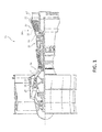
- gas turbine engine 20 may comprise a compressor section 24. Air may flow through compressor section 24 and into a combustion section 26, where it is mixed with a fuel source and ignited to produce hot combustion gasses. These hot combustion gasses may drive a series of turbine blades within a turbine section 28, which in turn drive, for example, one or more compressor section blades mechanically coupled thereto.
- Each of compressor section 24 and turbine section 28 may include alternating rows of rotor assemblies and vane assemblies (shown schematically) that carry airfoils that extend into core flow path C.
- the rotor assemblies may carry a plurality of rotating blades 25, while each vane assembly may carry a plurality of vanes 27 that extend into core flow path C.
- Blades 25 create or extract energy (in the form of pressure) from the core airflow that is communicated through gas turbine engine 20 along core flow path C.
- Vanes 27 direct the core airflow to blades 25 to either add or extract energy.
- gas turbine engine 20 including but not limited to airfoils of blades 25 and vanes 27 of compressor section 24 and turbine section 28, may be subjected to repetitive thermal cycling under widely ranging temperatures and pressures.
- the hardware of turbine section 28 is particularly subjected to relatively extreme operating conditions. Therefore, some components may require internal cooling schemes for cooling the parts during engine operation.
- this disclosure relates to gas turbine engine component cooling schemes that include lattice structures inside the walls of the gas turbine engine component.
- the exemplary structures described herein provide effective localized convective cooling for gas turbine engine components that may be subject to the hot combustion gases that are communicated through the core flow path C.
- Figure 2 illustrates a component 50 that may be incorporated into a gas turbine engine, such as gas turbine engine 20 of Figure 1 .
- component 50 is an airfoil.
- airfoil 50 may include a body portion 52 that extends between a leading edge portion 54 and a trailing edge portion 56.
- Body portion 52 may further include a first (pressure) side wall 58 and a second (suction) side wall 60 that are spaced apart from one another and axially extend between leading edge portion 54 and trailing edge portion 56.
- body portion 52 would also extend radially within gas turbine engine 20.
- a gas path 62 is communicated axially downstream through gas turbine engine 20 in a direction that extends from leading edge portion 54 toward trailing edge portion 56 of body portion 52.
- Gas path 62 represents the communication of core airflow along the core flow path C (see Figure 1 ).
- an airflow 68 can be circulated through a cooling scheme 64 within body portion 52.
- Airflow 68 may comprise a bleed airflow that sourced from gas path 62 or an air source provided from the compressor section 24 or any other portion of gas turbine engine 20.
- airflow 68 is communicated to cooling scheme 64 through a root portion of airfoil 50 (e.g., where the airfoil is a blade).
- Airflow 68 is generally of a lower temperature than the airflow of gas path 62 that is communicated across body portion 52.
- Airflow 68 may be circulated through cooling scheme 64 to transfer thermal energy from airfoil 50 to airflow 68 thereby cooling airfoil 50.
- Cooling scheme 64 may be disposed inside body portion 52 for cooling the internal and external surface areas of airfoil 50.
- cooling scheme 64 may include one or more cavities 72 that may extend inside of body portion 52 to establish cooling passages for receiving airflow 68 (or some other fluid).
- cooling scheme 64 is not necessarily limited to the configuration shown, and it will be appreciated that a greater or fewer number of cavities, including only a single cavity, may be defined inside of body portion 52.
- Cavities 72 communicate airflow 68 through cooling scheme 64, such as along a serpentine or linear path, to cool body portion 52.
- one or more lattice structures 80 may be incorporated into any section or sections of airfoil 50 as part of cooling scheme 64.
- the term "lattice structure" denotes a structure of known surface and flow areas.
- discrete portions of airfoil 50 may embody a lattice structure, or the entire airfoil 50 may be constructed of a lattice structure.
- lattice structures 80 can embody a hollow configuration in which cooling airflow 68 may be circulated inside various branches (e.g., passages) thereof.
- Lattice structure 80 can also comprise a solid configuration in which airflow 68 is communicated over and around such branches, which may be formed hollow or solid.
- Lattice structure 80 may be created using additive manufacturing processes such as direct metal laser sintering (DMLS), electron beam melting (EBM), select laser sintering (SLS), select laser melting (SLM), or the like.
- DMLS direct metal laser sintering
- EBM electron beam melting
- SLS select laser sintering
- SLM select laser melting
- Casting processes and additive manufacturing process used to produce a molybdenum core e.g., a refractory metal core
- Such additive manufacturing processes can include a powder bed technology and such casting processes can include a leaching process.
- a first exemplary lattice structure 180 extends between a first wall 182 and a second wall 184 of airfoil 50.
- first wall 182 is spaced from second wall 184.
- First wall 182 may be exposed to gas path 62, whereas second wall 184 may be remotely positioned from gas path 62.
- Airflow 68 may enter lattice structure 180 to convectively cool airfoil 50.
- Lattice structure 180 may comprise a plurality of nodes 192, a plurality of branches 194 that extend between the nodes 192, and a plurality of passages 196 between the branches 194 and the nodes 192.
- the number, size and distribution of nodes 192, branches 194, and passages 196 may vary from the specific configuration shown. Stated another way, the configuration illustrated by Figures 3A and 3B is but one possible design in accordance with various embodiments.
- nodes 192 and branches 194 of lattice structure 180 may be tailored to the specific cooling and structural needs of any given airfoil.
- nodes 192 and branches 194 may act as structural members that may be tailored to "tune" steady and unsteady airfoil vibration responses in order to resist and optimally manage steady and unsteady pressure forces, centrifugal bending and curling stresses, as well as provide for improved airfoil local and section average creep and untwist characteristics and capability.
- particular branches 194a may comprise a tapered configuration with, for example, a diameter d1 at a first portion thereof (along section A-A) that differs from a diameter d2 at a second portion thereof (along section B-B).
- Such a tapered configuration may, for example, increase or decrease the convective surface area of branches 194a, as well as altering the velocity of airflow within (in hollow configurations) branches 194a.
- Lattice structure 180 also includes a branch 194b with a non-linear (e.g., non-straight) configuration.
- branch 194b may comprise a bend or concavity between two nodes 192.
- a non-linear configuration provides increased convective cooling surface area along a particular direction (for example, the x or y axis) for a branch of respective diameter compared to that of a linearly configured (e.g., straight) branch of the same diameter.
- the non-linear configuration of branch 194b may provide tuning and/or structural benefits, such as improved vibration damping.
- Branches having any non-linear shape or configuration including a bent, curved, spiral, twist, or other non-linear configuration may be utilized. While nodes 192 and branches 194 are shown uniformly distributed throughout lattice structure 180, it will be appreciated that nodes 192 and branches 194 may alternatively be non-uniformly distributed.
- airflow 68 may be circulated through the open passages 196 to cool airfoil 50 in the space between walls 182, 184.
- airflow 68 is circulated through open passages 196, where it contacts and provides convective cooling to both solid nodes 192 and branches 194.
- nodes 192 and branches 194 may additionally act as structural members that resist pressure, rotation forces, vibration, and loads.
- airflow 68 may be circulated inside hollow nodes 192 and hollow branches 194 to cool airfoil 50 in the space between first wall 182 and second wall 184. Airflow 68 flows from each of the hollow branches 194 and coalesces into nodes 192, which serve as a plenum for the airflow 68 to be redistributed to the next set of hollow branches 194 and hollow nodes 192.
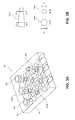
- a second exemplary embodiment of a solid lattice structure 280 includes a plurality of nodes 292, a plurality of branches 294 that extend between nodes 292, and a plurality of open passages 296 between branches 294 and nodes 292.
- Lattice structure 280 includes branches and/or nodes with different sizes and/or shapes.
- lattice structure 280 comprises a branch 294a with a generally cylindrical configuration having a uniform diameter d3 along the entire length thereof, and branch 284b with a generally cylindrical configuration having a diameter d4 along the entire length thereof.
- d4 is different from d3. Any number of branches having different diameters from one other may be utilized.
- branch 294a may, for example, comprise a generally hollow cylindrical configuration having an inner surface with a non-uniform surface profile 297.
- Non-uniform surface profile 297 may increase turbulence of the air passing through the inside of branch 294a.
- non-uniform surface profile 297 may comprise protrusions, bumps, or other textured structure configured to provide a non-uniform surface profile to the inside surface of branch 294a.
- branch 294a may comprise an outer surface having a non-uniform surface profile 298. Similar to profile 297, non-uniform surface profile 298 may comprise protrusions, bumps, or other textured structure.
- Non-uniform surface profiles may increase turbulence of the air passing along the inner and/or outer surfaces of branch 294a.
- structure 280 may comprise a branch 294c having a cross section 299.
- cross section 299 comprises a non-circular, closed curve shape such as an oval.
- cross section 299 comprises a non-circular, polygonal shape, such as a rectangle, square, trapezoid, or any other polygon.
- cross section 299 may comprise any shape.
- solid lattice structures 80, 180, 280 establish a ratio of cooling volume to structural area.
- the cooling volume is determined by open passages, while the structural area is the total surface area of nodes and branches.
- the amount of cooling volume exceeds the structural area (cooling volume > structural area).
- a ratio of the cooling volume to the structural volume is less than 1 (cooling volume ⁇ structural area).
- a ratio of the cooling volume to the structural area is between 1 and 4.
- Other configurations are also contemplated.
- lattice structures of Figures 3A-3B and 4A-4C are not intended to be limiting. It will be appreciated that because these lattice structures are engineered structures, the characteristics of the components of these structures may be tailored to the specific cooling and structural needs of any given gas turbine engine component. Stated another way, lattice structures may be tailored to match external heat load, local cooling flow pressure and local life requirements by changing the design and density of the lattice structure components, such as the nodes and branches. The actual design of any given lattice structure may depend on geometry specifications, pressure loss, local cooling flow, cooling air heat pickup, thermal efficiency, overall cooling effectiveness, aerodynamic mixing, and produceability considerations, among other gas turbine engine specific parameters. In various embodiments, lattice structures are sized based on a minimum size that may be effectively manufactured and that is not susceptible to becoming plugged by dirt or other debris.
- the component of gas turbine engine 20 which incorporates the lattice structures described above may include a non-airfoil component, including but not limited to, a blade outer air seal (BOAS), a combustor, an augmentor panel, a turbine exhaust case liner, or any other part that may require dedicated cooling.
- a non-airfoil component including but not limited to, a blade outer air seal (BOAS), a combustor, an augmentor panel, a turbine exhaust case liner, or any other part that may require dedicated cooling.
- the exemplary lattice structures described in this disclosure may be incorporated into any relatively high heat load gas turbine engine applications where convective cooling is desired.
- the lattice structures of this disclosure may be implemented as a co-flow or counter-flow configurations to more efficiently provide localized convective cooling to achieve extended component operating life.
- references to "one embodiment,” “an embodiment,” “an example embodiment,” etc. indicate that the embodiment described may include a particular feature, structure, or characteristic, but every embodiment may not necessarily include the particular feature, structure, or characteristic. Moreover, such phrases are not necessarily referring to the same embodiment. Further, when a particular feature, structure, or characteristic is described in connection with an embodiment, it is submitted that it is within the knowledge of one skilled in the art to affect such feature, structure, or characteristic in connection with other embodiments whether or not explicitly described. After reading the description, it will be apparent to one skilled in the relevant art(s) how to implement the disclosure in alternative embodiments.
Landscapes
- Engineering & Computer Science (AREA)
- Mechanical Engineering (AREA)
- General Engineering & Computer Science (AREA)
- Chemical & Material Sciences (AREA)
- Combustion & Propulsion (AREA)
- Turbine Rotor Nozzle Sealing (AREA)
Applications Claiming Priority (1)
| Application Number | Priority Date | Filing Date | Title |
|---|---|---|---|
| US201462078608P | 2014-11-12 | 2014-11-12 |
Publications (2)
| Publication Number | Publication Date |
|---|---|
| EP3020924A1 true EP3020924A1 (de) | 2016-05-18 |
| EP3020924B1 EP3020924B1 (de) | 2020-10-14 |
Family
ID=54366078
Family Applications (1)
| Application Number | Title | Priority Date | Filing Date |
|---|---|---|---|
| EP15192779.5A Active EP3020924B1 (de) | 2014-11-12 | 2015-11-03 | Gasturbinen bauteil und verfahren mit kühlgitter-struktur |
Country Status (2)
| Country | Link |
|---|---|
| US (1) | US9982544B2 (de) |
| EP (1) | EP3020924B1 (de) |
Cited By (4)
| Publication number | Priority date | Publication date | Assignee | Title |
|---|---|---|---|---|
| EP3056671A1 (de) * | 2015-02-10 | 2016-08-17 | United Technologies Corporation | Gasturbinenmotorkomponente mit vaskulärem kühlungssystem |
| EP3301367A1 (de) * | 2016-09-30 | 2018-04-04 | Siemens Aktiengesellschaft | Maschinenteil, insbesondere eine turbomaschinenkomponente mit kühlenden eigenschaften und verfahren für die herstellung und den betrieb |
| CN108733868A (zh) * | 2017-03-17 | 2018-11-02 | 通用电气公司 | 用于基于飞行数据的参数调谐和配置的方法和系统 |
| US10774653B2 (en) | 2018-12-11 | 2020-09-15 | Raytheon Technologies Corporation | Composite gas turbine engine component with lattice structure |
Families Citing this family (5)
| Publication number | Priority date | Publication date | Assignee | Title |
|---|---|---|---|---|
| EP2977679B1 (de) * | 2014-07-22 | 2019-08-28 | United Technologies Corporation | Brennkammerwand für einen gasturbinenmotor und verfahren zur akustischen dämpfung |
| DE102015219530A1 (de) * | 2015-10-08 | 2017-04-13 | Rolls-Royce Deutschland Ltd & Co Kg | Schaufel für eine Strömungsmaschine, Turbofantriebwerk und ein Verfahren zur Herstellung einer Schaufel |
| GB2567445B (en) * | 2017-10-11 | 2020-07-29 | Fokker Aerostructures Bv | Noise attenuation panel |
| US10502093B2 (en) * | 2017-12-13 | 2019-12-10 | Pratt & Whitney Canada Corp. | Turbine shroud cooling |
| US11702992B2 (en) * | 2021-12-03 | 2023-07-18 | Raytheon Company | Combustor wall core with resonator and/or damper elements |
Citations (3)
| Publication number | Priority date | Publication date | Assignee | Title |
|---|---|---|---|---|
| EP2011970A2 (de) * | 2007-07-06 | 2009-01-07 | United Technologies Corporation | Verstärkte Profile |
| US20130276461A1 (en) * | 2012-04-24 | 2013-10-24 | Sergio M. Loureiro | Airfoil having internal lattice network |
| WO2014105108A1 (en) * | 2012-12-28 | 2014-07-03 | United Technologies Corporation | Gas turbine engine component having vascular engineered lattice structure |
Family Cites Families (1)
| Publication number | Priority date | Publication date | Assignee | Title |
|---|---|---|---|---|
| US6402470B1 (en) * | 1999-10-05 | 2002-06-11 | United Technologies Corporation | Method and apparatus for cooling a wall within a gas turbine engine |
-
2015
- 2015-09-14 US US14/852,956 patent/US9982544B2/en active Active
- 2015-11-03 EP EP15192779.5A patent/EP3020924B1/de active Active
Patent Citations (3)
| Publication number | Priority date | Publication date | Assignee | Title |
|---|---|---|---|---|
| EP2011970A2 (de) * | 2007-07-06 | 2009-01-07 | United Technologies Corporation | Verstärkte Profile |
| US20130276461A1 (en) * | 2012-04-24 | 2013-10-24 | Sergio M. Loureiro | Airfoil having internal lattice network |
| WO2014105108A1 (en) * | 2012-12-28 | 2014-07-03 | United Technologies Corporation | Gas turbine engine component having vascular engineered lattice structure |
Cited By (9)
| Publication number | Priority date | Publication date | Assignee | Title |
|---|---|---|---|---|
| EP3056671A1 (de) * | 2015-02-10 | 2016-08-17 | United Technologies Corporation | Gasturbinenmotorkomponente mit vaskulärem kühlungssystem |
| US10094287B2 (en) | 2015-02-10 | 2018-10-09 | United Technologies Corporation | Gas turbine engine component with vascular cooling scheme |
| EP3301367A1 (de) * | 2016-09-30 | 2018-04-04 | Siemens Aktiengesellschaft | Maschinenteil, insbesondere eine turbomaschinenkomponente mit kühlenden eigenschaften und verfahren für die herstellung und den betrieb |
| WO2018060200A1 (en) * | 2016-09-30 | 2018-04-05 | Siemens Aktiengesellschaft | Machine component, particularly a turbomachine component, with cooling features and a method for manufacturing and of operation |
| US11371438B2 (en) | 2016-09-30 | 2022-06-28 | Siemens Energy Global GmbH & Co. KG | Machine component, particularly a turbomachine component, with cooling features and a method for manufacturing and of operation |
| CN108733868A (zh) * | 2017-03-17 | 2018-11-02 | 通用电气公司 | 用于基于飞行数据的参数调谐和配置的方法和系统 |
| CN108733868B (zh) * | 2017-03-17 | 2022-05-13 | 通用电气公司 | 用于基于飞行数据的参数调谐和配置的方法和系统 |
| US10774653B2 (en) | 2018-12-11 | 2020-09-15 | Raytheon Technologies Corporation | Composite gas turbine engine component with lattice structure |
| US11168568B2 (en) | 2018-12-11 | 2021-11-09 | Raytheon Technologies Corporation | Composite gas turbine engine component with lattice |
Also Published As
| Publication number | Publication date |
|---|---|
| US9982544B2 (en) | 2018-05-29 |
| US20160194967A1 (en) | 2016-07-07 |
| EP3020924B1 (de) | 2020-10-14 |
Similar Documents
| Publication | Publication Date | Title |
|---|---|---|
| EP3020924B1 (de) | Gasturbinen bauteil und verfahren mit kühlgitter-struktur | |
| US10662781B2 (en) | Gas turbine engine component having vascular engineered lattice structure | |
| US10731473B2 (en) | Gas turbine engine component having engineered vascular structure | |
| EP3179042B1 (de) | Gasturbinenmotorkomponente mit konstruierter vaskulärer gitterstruktur | |
| US8668453B2 (en) | Cooling system having reduced mass pin fins for components in a gas turbine engine | |
| US10221694B2 (en) | Gas turbine engine component having vascular engineered lattice structure | |
| US7824150B1 (en) | Multiple piece turbine airfoil | |
| US7828515B1 (en) | Multiple piece turbine airfoil | |
| KR102323269B1 (ko) | 에어포일 리딩 에지 후미의 나팔형 중앙 공동 | |
| US11339669B2 (en) | Turbine blade and gas turbine | |
| EP2434096A2 (de) | Gasturbinenschaufel mit einem Leitungssockel | |
| EP3056671B1 (de) | Gasturbinenmotorkomponente mit vaskulärem kühlungssystem | |
| JP6329657B2 (ja) | タービンシュラウドの密封冷却 | |
| JP6870964B2 (ja) | Cmc熱クランプ | |
| EP3064712A1 (de) | Ablenkplatteneinsatz | |
| EP3441568B1 (de) | Turbomaschinenprallkühleinsatz | |
| WO2017039568A1 (en) | Turbine airfoil cooling channel with fenced pedestals | |
| EP3170980B1 (de) | Gasturbinenkomponenten mit gitterkühlstruktur und zugehöriges herstellungsverfahren |
Legal Events
| Date | Code | Title | Description |
|---|---|---|---|
| PUAI | Public reference made under article 153(3) epc to a published international application that has entered the european phase |
Free format text: ORIGINAL CODE: 0009012 |
|
| AK | Designated contracting states |
Kind code of ref document: A1 Designated state(s): AL AT BE BG CH CY CZ DE DK EE ES FI FR GB GR HR HU IE IS IT LI LT LU LV MC MK MT NL NO PL PT RO RS SE SI SK SM TR |
|
| AX | Request for extension of the european patent |
Extension state: BA ME |
|
| RAP1 | Party data changed (applicant data changed or rights of an application transferred) |
Owner name: UNITED TECHNOLOGIES CORPORATION |
|
| STAA | Information on the status of an ep patent application or granted ep patent |
Free format text: STATUS: REQUEST FOR EXAMINATION WAS MADE |
|
| 17P | Request for examination filed |
Effective date: 20161117 |
|
| RBV | Designated contracting states (corrected) |
Designated state(s): AL AT BE BG CH CY CZ DE DK EE ES FI FR GB GR HR HU IE IS IT LI LT LU LV MC MK MT NL NO PL PT RO RS SE SI SK SM TR |
|
| STAA | Information on the status of an ep patent application or granted ep patent |
Free format text: STATUS: EXAMINATION IS IN PROGRESS |
|
| 17Q | First examination report despatched |
Effective date: 20180803 |
|
| GRAP | Despatch of communication of intention to grant a patent |
Free format text: ORIGINAL CODE: EPIDOSNIGR1 |
|
| STAA | Information on the status of an ep patent application or granted ep patent |
Free format text: STATUS: GRANT OF PATENT IS INTENDED |
|
| INTG | Intention to grant announced |
Effective date: 20200519 |
|
| GRAS | Grant fee paid |
Free format text: ORIGINAL CODE: EPIDOSNIGR3 |
|
| GRAA | (expected) grant |
Free format text: ORIGINAL CODE: 0009210 |
|
| STAA | Information on the status of an ep patent application or granted ep patent |
Free format text: STATUS: THE PATENT HAS BEEN GRANTED |
|
| AK | Designated contracting states |
Kind code of ref document: B1 Designated state(s): AL AT BE BG CH CY CZ DE DK EE ES FI FR GB GR HR HU IE IS IT LI LT LU LV MC MK MT NL NO PL PT RO RS SE SI SK SM TR |
|
| REG | Reference to a national code |
Ref country code: GB Ref legal event code: FG4D |
|
| REG | Reference to a national code |
Ref country code: AT Ref legal event code: REF Ref document number: 1323787 Country of ref document: AT Kind code of ref document: T Effective date: 20201015 Ref country code: CH Ref legal event code: EP |
|
| REG | Reference to a national code |
Ref country code: DE Ref legal event code: R096 Ref document number: 602015060392 Country of ref document: DE |
|
| REG | Reference to a national code |
Ref country code: IE Ref legal event code: FG4D |
|
| REG | Reference to a national code |
Ref country code: AT Ref legal event code: MK05 Ref document number: 1323787 Country of ref document: AT Kind code of ref document: T Effective date: 20201014 |
|
| REG | Reference to a national code |
Ref country code: NL Ref legal event code: MP Effective date: 20201014 |
|
| RAP2 | Party data changed (patent owner data changed or rights of a patent transferred) |
Owner name: RAYTHEON TECHNOLOGIES CORPORATION |
|
| PG25 | Lapsed in a contracting state [announced via postgrant information from national office to epo] |
Ref country code: PT Free format text: LAPSE BECAUSE OF FAILURE TO SUBMIT A TRANSLATION OF THE DESCRIPTION OR TO PAY THE FEE WITHIN THE PRESCRIBED TIME-LIMIT Effective date: 20210215 Ref country code: NL Free format text: LAPSE BECAUSE OF FAILURE TO SUBMIT A TRANSLATION OF THE DESCRIPTION OR TO PAY THE FEE WITHIN THE PRESCRIBED TIME-LIMIT Effective date: 20201014 Ref country code: NO Free format text: LAPSE BECAUSE OF FAILURE TO SUBMIT A TRANSLATION OF THE DESCRIPTION OR TO PAY THE FEE WITHIN THE PRESCRIBED TIME-LIMIT Effective date: 20210114 Ref country code: RS Free format text: LAPSE BECAUSE OF FAILURE TO SUBMIT A TRANSLATION OF THE DESCRIPTION OR TO PAY THE FEE WITHIN THE PRESCRIBED TIME-LIMIT Effective date: 20201014 Ref country code: FI Free format text: LAPSE BECAUSE OF FAILURE TO SUBMIT A TRANSLATION OF THE DESCRIPTION OR TO PAY THE FEE WITHIN THE PRESCRIBED TIME-LIMIT Effective date: 20201014 Ref country code: GR Free format text: LAPSE BECAUSE OF FAILURE TO SUBMIT A TRANSLATION OF THE DESCRIPTION OR TO PAY THE FEE WITHIN THE PRESCRIBED TIME-LIMIT Effective date: 20210115 |
|
| REG | Reference to a national code |
Ref country code: LT Ref legal event code: MG4D |
|
| PG25 | Lapsed in a contracting state [announced via postgrant information from national office to epo] |
Ref country code: AT Free format text: LAPSE BECAUSE OF FAILURE TO SUBMIT A TRANSLATION OF THE DESCRIPTION OR TO PAY THE FEE WITHIN THE PRESCRIBED TIME-LIMIT Effective date: 20201014 Ref country code: ES Free format text: LAPSE BECAUSE OF FAILURE TO SUBMIT A TRANSLATION OF THE DESCRIPTION OR TO PAY THE FEE WITHIN THE PRESCRIBED TIME-LIMIT Effective date: 20201014 Ref country code: BG Free format text: LAPSE BECAUSE OF FAILURE TO SUBMIT A TRANSLATION OF THE DESCRIPTION OR TO PAY THE FEE WITHIN THE PRESCRIBED TIME-LIMIT Effective date: 20210114 Ref country code: IS Free format text: LAPSE BECAUSE OF FAILURE TO SUBMIT A TRANSLATION OF THE DESCRIPTION OR TO PAY THE FEE WITHIN THE PRESCRIBED TIME-LIMIT Effective date: 20210214 Ref country code: PL Free format text: LAPSE BECAUSE OF FAILURE TO SUBMIT A TRANSLATION OF THE DESCRIPTION OR TO PAY THE FEE WITHIN THE PRESCRIBED TIME-LIMIT Effective date: 20201014 Ref country code: LV Free format text: LAPSE BECAUSE OF FAILURE TO SUBMIT A TRANSLATION OF THE DESCRIPTION OR TO PAY THE FEE WITHIN THE PRESCRIBED TIME-LIMIT Effective date: 20201014 Ref country code: SE Free format text: LAPSE BECAUSE OF FAILURE TO SUBMIT A TRANSLATION OF THE DESCRIPTION OR TO PAY THE FEE WITHIN THE PRESCRIBED TIME-LIMIT Effective date: 20201014 |
|
| PG25 | Lapsed in a contracting state [announced via postgrant information from national office to epo] |
Ref country code: HR Free format text: LAPSE BECAUSE OF FAILURE TO SUBMIT A TRANSLATION OF THE DESCRIPTION OR TO PAY THE FEE WITHIN THE PRESCRIBED TIME-LIMIT Effective date: 20201014 |
|
| REG | Reference to a national code |
Ref country code: CH Ref legal event code: PL |
|
| REG | Reference to a national code |
Ref country code: DE Ref legal event code: R097 Ref document number: 602015060392 Country of ref document: DE |
|
| PG25 | Lapsed in a contracting state [announced via postgrant information from national office to epo] |
Ref country code: SM Free format text: LAPSE BECAUSE OF FAILURE TO SUBMIT A TRANSLATION OF THE DESCRIPTION OR TO PAY THE FEE WITHIN THE PRESCRIBED TIME-LIMIT Effective date: 20201014 Ref country code: CZ Free format text: LAPSE BECAUSE OF FAILURE TO SUBMIT A TRANSLATION OF THE DESCRIPTION OR TO PAY THE FEE WITHIN THE PRESCRIBED TIME-LIMIT Effective date: 20201014 Ref country code: EE Free format text: LAPSE BECAUSE OF FAILURE TO SUBMIT A TRANSLATION OF THE DESCRIPTION OR TO PAY THE FEE WITHIN THE PRESCRIBED TIME-LIMIT Effective date: 20201014 Ref country code: SK Free format text: LAPSE BECAUSE OF FAILURE TO SUBMIT A TRANSLATION OF THE DESCRIPTION OR TO PAY THE FEE WITHIN THE PRESCRIBED TIME-LIMIT Effective date: 20201014 Ref country code: RO Free format text: LAPSE BECAUSE OF FAILURE TO SUBMIT A TRANSLATION OF THE DESCRIPTION OR TO PAY THE FEE WITHIN THE PRESCRIBED TIME-LIMIT Effective date: 20201014 Ref country code: LT Free format text: LAPSE BECAUSE OF FAILURE TO SUBMIT A TRANSLATION OF THE DESCRIPTION OR TO PAY THE FEE WITHIN THE PRESCRIBED TIME-LIMIT Effective date: 20201014 Ref country code: MC Free format text: LAPSE BECAUSE OF FAILURE TO SUBMIT A TRANSLATION OF THE DESCRIPTION OR TO PAY THE FEE WITHIN THE PRESCRIBED TIME-LIMIT Effective date: 20201014 Ref country code: LU Free format text: LAPSE BECAUSE OF NON-PAYMENT OF DUE FEES Effective date: 20201103 |
|
| REG | Reference to a national code |
Ref country code: BE Ref legal event code: MM Effective date: 20201130 |
|
| PLBE | No opposition filed within time limit |
Free format text: ORIGINAL CODE: 0009261 |
|
| STAA | Information on the status of an ep patent application or granted ep patent |
Free format text: STATUS: NO OPPOSITION FILED WITHIN TIME LIMIT |
|
| PG25 | Lapsed in a contracting state [announced via postgrant information from national office to epo] |
Ref country code: LI Free format text: LAPSE BECAUSE OF NON-PAYMENT OF DUE FEES Effective date: 20201130 Ref country code: CH Free format text: LAPSE BECAUSE OF NON-PAYMENT OF DUE FEES Effective date: 20201130 Ref country code: DK Free format text: LAPSE BECAUSE OF FAILURE TO SUBMIT A TRANSLATION OF THE DESCRIPTION OR TO PAY THE FEE WITHIN THE PRESCRIBED TIME-LIMIT Effective date: 20201014 |
|
| 26N | No opposition filed |
Effective date: 20210715 |
|
| PG25 | Lapsed in a contracting state [announced via postgrant information from national office to epo] |
Ref country code: AL Free format text: LAPSE BECAUSE OF FAILURE TO SUBMIT A TRANSLATION OF THE DESCRIPTION OR TO PAY THE FEE WITHIN THE PRESCRIBED TIME-LIMIT Effective date: 20201014 Ref country code: IE Free format text: LAPSE BECAUSE OF NON-PAYMENT OF DUE FEES Effective date: 20201103 Ref country code: IT Free format text: LAPSE BECAUSE OF FAILURE TO SUBMIT A TRANSLATION OF THE DESCRIPTION OR TO PAY THE FEE WITHIN THE PRESCRIBED TIME-LIMIT Effective date: 20201014 |
|
| PG25 | Lapsed in a contracting state [announced via postgrant information from national office to epo] |
Ref country code: SI Free format text: LAPSE BECAUSE OF FAILURE TO SUBMIT A TRANSLATION OF THE DESCRIPTION OR TO PAY THE FEE WITHIN THE PRESCRIBED TIME-LIMIT Effective date: 20201014 |
|
| PG25 | Lapsed in a contracting state [announced via postgrant information from national office to epo] |
Ref country code: IS Free format text: LAPSE BECAUSE OF FAILURE TO SUBMIT A TRANSLATION OF THE DESCRIPTION OR TO PAY THE FEE WITHIN THE PRESCRIBED TIME-LIMIT Effective date: 20210214 Ref country code: TR Free format text: LAPSE BECAUSE OF FAILURE TO SUBMIT A TRANSLATION OF THE DESCRIPTION OR TO PAY THE FEE WITHIN THE PRESCRIBED TIME-LIMIT Effective date: 20201014 Ref country code: MT Free format text: LAPSE BECAUSE OF FAILURE TO SUBMIT A TRANSLATION OF THE DESCRIPTION OR TO PAY THE FEE WITHIN THE PRESCRIBED TIME-LIMIT Effective date: 20201014 Ref country code: CY Free format text: LAPSE BECAUSE OF FAILURE TO SUBMIT A TRANSLATION OF THE DESCRIPTION OR TO PAY THE FEE WITHIN THE PRESCRIBED TIME-LIMIT Effective date: 20201014 |
|
| PG25 | Lapsed in a contracting state [announced via postgrant information from national office to epo] |
Ref country code: MK Free format text: LAPSE BECAUSE OF FAILURE TO SUBMIT A TRANSLATION OF THE DESCRIPTION OR TO PAY THE FEE WITHIN THE PRESCRIBED TIME-LIMIT Effective date: 20201014 |
|
| PG25 | Lapsed in a contracting state [announced via postgrant information from national office to epo] |
Ref country code: BE Free format text: LAPSE BECAUSE OF NON-PAYMENT OF DUE FEES Effective date: 20201130 |
|
| P01 | Opt-out of the competence of the unified patent court (upc) registered |
Effective date: 20230520 |
|
| REG | Reference to a national code |
Ref country code: DE Ref legal event code: R081 Ref document number: 602015060392 Country of ref document: DE Owner name: RTX CORPORATION (N.D.GES.D. STAATES DELAWARE),, US Free format text: FORMER OWNER: UNITED TECHNOLOGIES CORPORATION, FARMINGTON, CONN., US |
|
| PGFP | Annual fee paid to national office [announced via postgrant information from national office to epo] |
Ref country code: DE Payment date: 20251022 Year of fee payment: 11 |
|
| PGFP | Annual fee paid to national office [announced via postgrant information from national office to epo] |
Ref country code: GB Payment date: 20251023 Year of fee payment: 11 |
|
| PGFP | Annual fee paid to national office [announced via postgrant information from national office to epo] |
Ref country code: FR Payment date: 20251022 Year of fee payment: 11 |