EP3020930A1 - Plate-forme avec des caractéristiques de bord d'attaque - Google Patents
Plate-forme avec des caractéristiques de bord d'attaque Download PDFInfo
- Publication number
- EP3020930A1 EP3020930A1 EP15194388.3A EP15194388A EP3020930A1 EP 3020930 A1 EP3020930 A1 EP 3020930A1 EP 15194388 A EP15194388 A EP 15194388A EP 3020930 A1 EP3020930 A1 EP 3020930A1
- Authority
- EP
- European Patent Office
- Prior art keywords
- platform
- base surface
- upstream
- extending flange
- axial position
- Prior art date
- Legal status (The legal status is an assumption and is not a legal conclusion. Google has not performed a legal analysis and makes no representation as to the accuracy of the status listed.)
- Granted
Links
Images


Classifications
-
- F—MECHANICAL ENGINEERING; LIGHTING; HEATING; WEAPONS; BLASTING
- F01—MACHINES OR ENGINES IN GENERAL; ENGINE PLANTS IN GENERAL; STEAM ENGINES
- F01D—NON-POSITIVE DISPLACEMENT MACHINES OR ENGINES, e.g. STEAM TURBINES
- F01D11/00—Preventing or minimising internal leakage of working-fluid, e.g. between stages
- F01D11/02—Preventing or minimising internal leakage of working-fluid, e.g. between stages by non-contact sealings, e.g. of labyrinth type
- F01D11/04—Preventing or minimising internal leakage of working-fluid, e.g. between stages by non-contact sealings, e.g. of labyrinth type using sealing fluid, e.g. steam
-
- F—MECHANICAL ENGINEERING; LIGHTING; HEATING; WEAPONS; BLASTING
- F01—MACHINES OR ENGINES IN GENERAL; ENGINE PLANTS IN GENERAL; STEAM ENGINES
- F01D—NON-POSITIVE DISPLACEMENT MACHINES OR ENGINES, e.g. STEAM TURBINES
- F01D11/00—Preventing or minimising internal leakage of working-fluid, e.g. between stages
- F01D11/001—Preventing or minimising internal leakage of working-fluid, e.g. between stages for sealing space between stator blade and rotor
-
- F—MECHANICAL ENGINEERING; LIGHTING; HEATING; WEAPONS; BLASTING
- F01—MACHINES OR ENGINES IN GENERAL; ENGINE PLANTS IN GENERAL; STEAM ENGINES
- F01D—NON-POSITIVE DISPLACEMENT MACHINES OR ENGINES, e.g. STEAM TURBINES
- F01D11/00—Preventing or minimising internal leakage of working-fluid, e.g. between stages
- F01D11/005—Sealing means between non relatively rotating elements
-
- F—MECHANICAL ENGINEERING; LIGHTING; HEATING; WEAPONS; BLASTING
- F01—MACHINES OR ENGINES IN GENERAL; ENGINE PLANTS IN GENERAL; STEAM ENGINES
- F01D—NON-POSITIVE DISPLACEMENT MACHINES OR ENGINES, e.g. STEAM TURBINES
- F01D9/00—Stators
- F01D9/02—Nozzles; Nozzle boxes; Stator blades; Guide conduits, e.g. individual nozzles
-
- F—MECHANICAL ENGINEERING; LIGHTING; HEATING; WEAPONS; BLASTING
- F05—INDEXING SCHEMES RELATING TO ENGINES OR PUMPS IN VARIOUS SUBCLASSES OF CLASSES F01-F04
- F05D—INDEXING SCHEME FOR ASPECTS RELATING TO NON-POSITIVE-DISPLACEMENT MACHINES OR ENGINES, GAS-TURBINES OR JET-PROPULSION PLANTS
- F05D2240/00—Components
- F05D2240/10—Stators
- F05D2240/12—Fluid guiding means, e.g. vanes
- F05D2240/127—Vortex generators, turbulators, or the like, for mixing
-
- F—MECHANICAL ENGINEERING; LIGHTING; HEATING; WEAPONS; BLASTING
- F05—INDEXING SCHEMES RELATING TO ENGINES OR PUMPS IN VARIOUS SUBCLASSES OF CLASSES F01-F04
- F05D—INDEXING SCHEME FOR ASPECTS RELATING TO NON-POSITIVE-DISPLACEMENT MACHINES OR ENGINES, GAS-TURBINES OR JET-PROPULSION PLANTS
- F05D2240/00—Components
- F05D2240/55—Seals
- F05D2240/57—Leaf seals
-
- F—MECHANICAL ENGINEERING; LIGHTING; HEATING; WEAPONS; BLASTING
- F05—INDEXING SCHEMES RELATING TO ENGINES OR PUMPS IN VARIOUS SUBCLASSES OF CLASSES F01-F04
- F05D—INDEXING SCHEME FOR ASPECTS RELATING TO NON-POSITIVE-DISPLACEMENT MACHINES OR ENGINES, GAS-TURBINES OR JET-PROPULSION PLANTS
- F05D2240/00—Components
- F05D2240/80—Platforms for stationary or moving blades
Definitions
- the present disclosure relates to airfoil platforms, such as rotor blade platforms and vane platforms.
- turbomachines as in gas turbine engines, include multiple stages of rotor blades and vanes to condition and guide fluid flow through the compressor and/or turbine sections.
- Stages in some engine sections can include alternating rotor blade stages and stator vane stages.
- Each respective stage includes at least one platform for mounting the rotors and stators.
- the platforms of a given stage are generally mounted circumferentially together using a feather seal. Feather seals between the platforms in a given stage can help to prevent ingestion of unwanted fluid flow at the axial interfaces between the platforms.
- Ingestion of unwanted fluid flow can also occur at the circumferential interface between the platforms of two separate stages.
- high pressure purge flow from the compressor can be used to reduce ingestion, but can potentially cause performance losses as a trade off.
- a platform includes a platform body.
- the platform body has an airfoil support surface, an axially extending base surface opposite the airfoil support surface, and a leading edge.
- the leading edge includes an upstream extending flange with a raised portion and a trough portion downstream of and radially inward from the raised portion.
- the raised portion and the trough portion are for holding a vortex of fluid flow.
- the upstream extending flange includes a converging surface connecting the upstream extending flange to the base surface. The converging surface converges in a direction toward the axially extending base surface and is at an angle relative to (i.e. inclined relative to) the base surface.
- the raised portion of the leading edge can be configured to be axially overlapped by a downstream extending flange of an upstream platform.
- the platform can include an axially extending feather seal opening defined between the airfoil support surface and the base surface.
- the axial position of the upstream edge of the feather seal opening can be substantially equal to the axial position of the intersection of the base surface and the converging surface, and/or the axial position of the upstream edge of the feather seal opening can be substantially equal to the axial position of the upstream edge of the base surface.
- the axial length of the raised portion can be substantially equal to the axial length of the opening of the trough portion.
- the airfoil support surface can be operatively connected to a stator vane.
- a turbomachine includes a first platform including a downstream extending flange and a second platform downstream of the first platform.
- the second platform includes an airfoil support surface and an axially extending base surface opposite the airfoil support surface, and a leading edge.
- the leading edge is similar to the leading edge described above.
- the downstream extending flange of the first platform axially overlaps the raised portion of the leading edge of the second platform. When at equilibrium temperature, the axial position of the downstream edge of the downstream extending flange is substantially equal to the axial position of the intersection of the raised portion and the trough portion.
- the second platform can include a feather seal opening, similar to the feather seal opening described above.
- the radial distance between a bottom of the trough portion and an outer surface of the downstream extending flange can be approximately two times the radius of curvature of the trough portion.
- the first platform can be a blade platform operatively connected to a rotor blade.
- the blade platform can be configured to move circumferentially with respect to the second platform while still maintaining an axial overlap between the downstream extending flange of the blade platform and the raised portion of the leading edge of the second platform.
- the second platform can be a vane platform operatively connected to a stator vane.
- a platform having: a platform body having: an airfoil support surface; an axially extending base surface opposite the airfoil support surface; and a leading edge including an upstream extending flange with a raised portion and a trough portion downstream of and radially inward from the raised portion for holding a vortex of fluid flow, and wherein the upstream extending flange includes a converging surface connecting the upstream extending flange to the base surface, wherein the converging surface converges in a direction toward the axially extending base surface and is at an angle relative to (i.e. inclined relative to) the base surface.
- the raised portion of the leading edge may be configured to be axially overlapped by a downstream extending flange of an upstream platform.
- further embodiments may include an axially extending feather seal opening defined between the airfoil support surface and the base surface.
- an axial position of an upstream edge of the feather seal opening may be substantially equal to an axial position of an intersection of the base surface and the converging surface.
- an axial position of an upstream edge of the feather seal opening may be substantially equal to an axial position of the upstream edge of the base surface.
- an axial length of the raised portion may be substantially equal to an axial length of an opening of the trough portion.
- the airfoil support surface may be operatively connected to a stator vane.
- a platform having: a platform body having: an airfoil support surface; an axially extending base surface opposite the airfoil support surface; an axially extending feather seal opening defined between the airfoil support surface and the base surface; and a leading edge including an upstream extending flange with a raised portion and a trough portion downstream of and radially inward from the raised portion for holding a vortex of fluid flow, wherein an axial position of an upstream edge of the feather seal opening is substantially equal to an axial position of the upstream edge of the base surface.
- the upstream extending flange includes a converging surface connecting the upstream extending flange to the base surface, wherein the converging surface converges in a direction toward the axially extending base surface and is at an angle relative to the base surface.
- the axial position of the upstream edge of the feather seal opening may be substantially equal to an axial position of an intersection of the base surface and the converging surface.
- a turbomachine having: a first platform including a downstream extending flange; and a second platform downstream of the first platform, wherein the second platform includes: an airfoil support surface; an axially extending base surface opposite the airfoil support surface; and a leading edge including an upstream extending flange with a raised portion and a trough portion downstream of and radially inward from the raised portion for holding a vortex of fluid flow, wherein the downstream extending flange of the first platform axially overlaps the raised portion of the leading edge of the second platform, and wherein, when at equilibrium temperature, an axial position of a downstream edge of the downstream extending flange is substantially equal to an axial position of an intersection of the raised portion and the trough portion.
- the upstream extending flange includes a converging surface connecting the upstream extending flange to the base surface, wherein the converging surface converges in a direction toward the axially extending base surface and is at an angle relative to the base surface.
- further embodiments may include an axially extending feather seal opening defined between the airfoil support surface and the base surface, wherein an upstream edge of the feather seal opening is defined at an axial position substantially equal to an axial position of an intersection of the base surface and the converging surface.
- further embodiments may include an axially extending feather seal opening defined between the airfoil support surface and the base surface.
- an axial position of an upstream edge of the feather seal opening may be substantially equal to an axial position of the upstream edge of the base surface.
- an axial length of the raised portion may be substantially equal to an axial length of an opening of the trough portion.
- a radial distance between a bottom of the trough portion and an outer surface of the downstream extending flange is approximately two times a radius of curvature of the trough portion.
- the first platform is a blade platform operatively connected to a rotor blade, wherein the blade platform is configured to move circumferentially with respect to the second platform while still maintaining an axial overlap between the downstream extending flange of the blade platform and the raised portion of the leading edge of the second platform.
- the second platform is a vane platform operatively connected to a stator vane.
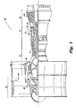
- FIG. 1 a schematic side elevation view of an exemplary embodiment of a turbomachine constructed in accordance with the disclosure is shown in Fig. 1 and is designated generally by reference character 100.
- FIG. 2 Other embodiments of turbomachines constructed in accordance with the disclosure, or aspects thereof, are provided in Fig. 2 , as will be described.
- a turbomachine 100 for example, a gas turbine engine, includes a fan section 22, a compressor section 24, a combustor section 26 and a turbine section 28.
- the fan section 22 drives air along a bypass flow path 21, while the compressor section 24 drives air along a core flow path, e.g. main gas path 111, for compression and communication into the combustor section 26 then expansion through the turbine section 28.
- the core airflow is compressed by a low pressure compressor 44 then a high pressure compressor 52, mixed and burned with fuel in a combustor 56, then expanded over a high pressure turbine 54 and a low pressure turbine 46.
- Gas turbine engine 100 includes a plurality of airfoil stages, for example blade stages 23 and vane stages 25, which are in main gas path 111.
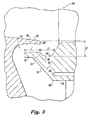
- gas turbine engine 100 includes a first platform 102, e.g. a blade platform, and a second platform 104, e.g. a vane platform, downstream of first platform 102.
- first and second platforms has respective platform bodies 103 and 105, respectively.
- First platform 102 is operatively connected to a rotor blade 107, for example a rotor blade in rotor blade stage 23, shown in Fig. 1 .
- Second platform 104 is a vane platform operatively connected to a stator vane 109. Both first and second platforms, 102 and 104, respectively, and their respective blade and vane, 107 and 109, respectively, are defined within a main gas path 111 of gas turbine engine 100.
- first and second platforms are shown and described herein as blade and vane platforms, respectively, first and second platforms can be just blade platforms or just vane platforms, the first platform can be a vane platform and the second platform can be a blade platform, and/or any other suitable variations thereof.
- first platform 102 includes a downstream extending flange 106.
- Second platform 104 includes an airfoil support surface 108 and an axially extending base surface 110, e.g. along longitudinal axis A, opposite airfoil support surface 108, and a leading edge 112.
- Leading edge 112 includes an upstream extending flange 114 with a raised portion 116 and a trough portion 118 downstream of and radially inward from raised portion 116.
- Raised portion 116 and trough portion 118 are configured to hold a vortex of fluid flow, as shown schematically with the swirling arrow, inhibiting ingestion of fluid from main gas path 111 into a rim cavity 113.
- Rim cavity 113 is defined radially inward from leading edge 112. It is contemplated that the discourager and trough configurations described above can be used in conjunction with purge flow, shown schematically by an arrow 115.
- first platform 102 Downstream extending flange 106 of first platform 102 axially overlaps raised portion 116 of leading edge 112 of second platform 104.
- first and second platforms, 102 and 104, respectively, are at equilibrium temperature an axial position of a downstream edge 120 of downstream extending flange 106 is substantially equal to an axial position of an intersection 121 of raised portion 116 and trough portion 118. Due to the axial position of raised portion 116, and the length of raised portion 116, described below, first platform 102 is configured to move circumferentially with respect to second platform 104 while still maintaining the axial overlap between downstream extending flange 106 of first platform 102 and raised portion 116 of leading edge 112 of second platform 104.
- second platform 104 includes an axially extending feather seal opening 124 defined between airfoil support surface 108 and base surface 110.
- An axial position of an upstream edge 126 of feather seal opening 124 is substantially equal to an axial position of an upstream edge 128 of base surface 110, e.g. at an intersection of base surface 110 and a converging surface 122.
- the axial position of feather seal opening 124 consequently affects the placement of a feather seal, not shown.
- This axial position of upstream edge 126 of feather seal opening 124 tends to reduce leakage of purge flow 115 at the axial interfaces between platforms in the same stage compared to traditional platform interfaces. This reduction increases the effectiveness of purge flow 115 in reducing the ingestion at the interface between blade platform 102 and vane platform 104, potentially reducing the amount of purge flow 115 required and reducing losses.
- Upstream extending flange 114 includes a converging surface 122 at an angle relative to axially extending base surface 110 and converges in a direction toward axially extending base surface 110, e.g. toward longitudinal axis A.
- Converging surface 122 connects upstream extending flange 114 to base surface 110.
- the increased thickness created by converging surface 122 allows for feather seal opening 124 to be defined farther upstream than feather seal openings found on traditional airfoil platforms, for example, a feather seal opening 324 as shown in Fig. 5 .
- a height H of raised portion 116 is can be as thin as manufacturing allows, for example 0.010 inches (0.025 cm) but can be thicker as needed to meet various design requirements, such as structural and thermal requirements.
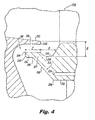
- turbomachine 200 is substantially similar to turbomachine 100, except that raised portion 216 is different from raised portion 116.
- Raised portion 216 has a break-edge 202 on the bottom radially inward corner, a rounded corner 204 on the top radially outward corner, and a blended surface 206 between raised portion 216 and converging surface 222.
- Break-edges, rounded corners and blended surfaces can be used in a variety of suitable locations throughout the platforms and are not limited to the specific corners and locations shown in Fig. 4 .
- the top radially outward corner can have a break-edge 202, and/or bottom radially inward corner can have a rounded corner 204.
- converging surface 122 also contributes to feather seal opening 124 being able to be defined further upstream than a traditional feather seal opening, e.g. a feather seal opening 324 of traditional second platform 304, shown in Fig. 5 .
- the incorporation of trough 118 tends to push feather seal opening 124 aft.
- the increase in the height E of the platform that converging surface 122 creates allows feather seal opening 124 to be moved forward, while still including trough 118.
- converging surface 122 is shown as an angled linear surface, converging surface 122 can be curved, stepped, or rounded. It is also contemplated that the average slope may be near radial (very steep) to near axial (very shallow), as needed to maintain a minimum gap between converging surface 122 and first platform 103.
- a radial distance B between a bottom 130 of trough portion 118 and an outer surface 132 of downstream extending flange 106 is approximately two times the radius of curvature of trough portion 118.
- An axial length C of raised portion 116 is substantially equal to an axial length D of an opening of the trough portion. It is contemplated that radial distance B can be approximately equal to axial length D in order to develop a vortex that acts to block the radial gap between downstream extending flange 106 and leading edge 112.
Landscapes
- Engineering & Computer Science (AREA)
- Mechanical Engineering (AREA)
- General Engineering & Computer Science (AREA)
- Structures Of Non-Positive Displacement Pumps (AREA)
Applications Claiming Priority (1)
| Application Number | Priority Date | Filing Date | Title |
|---|---|---|---|
| US201462078609P | 2014-11-12 | 2014-11-12 |
Publications (2)
| Publication Number | Publication Date |
|---|---|
| EP3020930A1 true EP3020930A1 (fr) | 2016-05-18 |
| EP3020930B1 EP3020930B1 (fr) | 2018-08-29 |
Family
ID=54540988
Family Applications (1)
| Application Number | Title | Priority Date | Filing Date |
|---|---|---|---|
| EP15194388.3A Active EP3020930B1 (fr) | 2014-11-12 | 2015-11-12 | Plate-forme avec des caractéristiques de bord d'attaque |
Country Status (2)
| Country | Link |
|---|---|
| US (2) | US10132182B2 (fr) |
| EP (1) | EP3020930B1 (fr) |
Cited By (1)
| Publication number | Priority date | Publication date | Assignee | Title |
|---|---|---|---|---|
| EP3037627B1 (fr) * | 2014-12-22 | 2020-02-05 | United Technologies Corporation | Géométrie matérielle permettant d'augmenter le chevauchement de pièce et de maintien du jeu |
Families Citing this family (3)
| Publication number | Priority date | Publication date | Assignee | Title |
|---|---|---|---|---|
| US10590781B2 (en) | 2016-12-21 | 2020-03-17 | General Electric Company | Turbine engine assembly with a component having a leading edge trough |
| US10633992B2 (en) * | 2017-03-08 | 2020-04-28 | Pratt & Whitney Canada Corp. | Rim seal |
| US12055044B1 (en) * | 2023-10-06 | 2024-08-06 | Pratt & Whitney Canada Corp. | Undercut groove and chamfer for rim seal |
Citations (4)
| Publication number | Priority date | Publication date | Assignee | Title |
|---|---|---|---|---|
| GB780382A (en) * | 1954-07-08 | 1957-07-31 | Rolls Royce | Improvements in or relating to multi-stage axial-flow compressors |
| US6152690A (en) * | 1997-06-18 | 2000-11-28 | Mitsubishi Heavy Industries, Ltd. | Sealing apparatus for gas turbine |
| WO2013130181A2 (fr) * | 2012-02-29 | 2013-09-06 | United Technologies Corporation | Bord de fuite de plateforme de profil à faible perte |
| EP2687682A2 (fr) * | 2012-07-19 | 2014-01-22 | Mitsubishi Heavy Industries, Ltd. | Turbine à gaz |
Family Cites Families (20)
| Publication number | Priority date | Publication date | Assignee | Title |
|---|---|---|---|---|
| US5429478A (en) * | 1994-03-31 | 1995-07-04 | United Technologies Corporation | Airfoil having a seal and an integral heat shield |
| US7249928B2 (en) * | 2005-04-01 | 2007-07-31 | General Electric Company | Turbine nozzle with purge cavity blend |
| US7189056B2 (en) * | 2005-05-31 | 2007-03-13 | Pratt & Whitney Canada Corp. | Blade and disk radial pre-swirlers |
| US7465152B2 (en) * | 2005-09-16 | 2008-12-16 | General Electric Company | Angel wing seals for turbine blades and methods for selecting stator, rotor and wing seal profiles |
| US20080145208A1 (en) * | 2006-12-19 | 2008-06-19 | General Electric Company | Bullnose seal turbine stage |
| US7578653B2 (en) * | 2006-12-19 | 2009-08-25 | General Electric Company | Ovate band turbine stage |
| US8262342B2 (en) * | 2008-07-10 | 2012-09-11 | Honeywell International Inc. | Gas turbine engine assemblies with recirculated hot gas ingestion |
| US8240987B2 (en) * | 2008-08-15 | 2012-08-14 | United Technologies Corp. | Gas turbine engine systems involving baffle assemblies |
| US8419356B2 (en) * | 2008-09-25 | 2013-04-16 | Siemens Energy, Inc. | Turbine seal assembly |
| US20120051930A1 (en) * | 2010-08-31 | 2012-03-01 | General Electric Company | Shrouded turbine blade with contoured platform and axial dovetail |
| US8727716B2 (en) * | 2010-08-31 | 2014-05-20 | General Electric Company | Turbine nozzle with contoured band |
| GB201112880D0 (en) * | 2011-07-27 | 2011-09-07 | Rolls Royce Plc | Blade cooling and sealing system |
| US8834122B2 (en) * | 2011-10-26 | 2014-09-16 | General Electric Company | Turbine bucket angel wing features for forward cavity flow control and related method |
| US8827643B2 (en) * | 2011-10-26 | 2014-09-09 | General Electric Company | Turbine bucket platform leading edge scalloping for performance and secondary flow and related method |
| US9022728B2 (en) * | 2011-10-28 | 2015-05-05 | United Technologies Corporation | Feather seal slot |
| US8967957B2 (en) * | 2011-11-03 | 2015-03-03 | General Electric Company | Rotating airfoil component of a turbomachine |
| US20130170983A1 (en) * | 2012-01-04 | 2013-07-04 | General Electric Company | Turbine assembly and method for reducing fluid flow between turbine components |
| US9097128B2 (en) * | 2012-02-28 | 2015-08-04 | General Electric Company | Seals for rotary devices and methods of producing the same |
| US9103213B2 (en) * | 2012-02-29 | 2015-08-11 | General Electric Company | Scalloped surface turbine stage with purge trough |
| US20140083113A1 (en) * | 2012-09-27 | 2014-03-27 | General Electric Company | Flow control tab for turbine section flow cavity |
-
2015
- 2015-11-10 US US14/937,360 patent/US10132182B2/en active Active
- 2015-11-12 EP EP15194388.3A patent/EP3020930B1/fr active Active
-
2018
- 2018-11-19 US US16/195,316 patent/US10844739B2/en active Active
Patent Citations (4)
| Publication number | Priority date | Publication date | Assignee | Title |
|---|---|---|---|---|
| GB780382A (en) * | 1954-07-08 | 1957-07-31 | Rolls Royce | Improvements in or relating to multi-stage axial-flow compressors |
| US6152690A (en) * | 1997-06-18 | 2000-11-28 | Mitsubishi Heavy Industries, Ltd. | Sealing apparatus for gas turbine |
| WO2013130181A2 (fr) * | 2012-02-29 | 2013-09-06 | United Technologies Corporation | Bord de fuite de plateforme de profil à faible perte |
| EP2687682A2 (fr) * | 2012-07-19 | 2014-01-22 | Mitsubishi Heavy Industries, Ltd. | Turbine à gaz |
Cited By (1)
| Publication number | Priority date | Publication date | Assignee | Title |
|---|---|---|---|---|
| EP3037627B1 (fr) * | 2014-12-22 | 2020-02-05 | United Technologies Corporation | Géométrie matérielle permettant d'augmenter le chevauchement de pièce et de maintien du jeu |
Also Published As
| Publication number | Publication date |
|---|---|
| US10844739B2 (en) | 2020-11-24 |
| US20190153885A1 (en) | 2019-05-23 |
| US20160130968A1 (en) | 2016-05-12 |
| EP3020930B1 (fr) | 2018-08-29 |
| US10132182B2 (en) | 2018-11-20 |
Similar Documents
| Publication | Publication Date | Title |
|---|---|---|
| US20240159151A1 (en) | Airfoil for a turbine engine | |
| US10822957B2 (en) | Fillet optimization for turbine airfoil | |
| US10436038B2 (en) | Turbine engine with an airfoil having a tip shelf outlet | |
| US7520726B2 (en) | HP turbine blade airfoil profile | |
| US7559746B2 (en) | LP turbine blade airfoil profile | |
| US7625183B2 (en) | LP turbine van airfoil profile | |
| US7559748B2 (en) | LP turbine blade airfoil profile | |
| US9581029B2 (en) | High pressure turbine blade cooling hole distribution | |
| US10502132B2 (en) | Gas turbine engine with an offtake | |
| US10233775B2 (en) | Engine component for a gas turbine engine | |
| US10844739B2 (en) | Platforms with leading edge features | |
| US10267161B2 (en) | Gas turbine engine with fillet film holes | |
| US11852034B2 (en) | Tandem rotor blades | |
| US20170306768A1 (en) | Turbine engine shroud assembly | |
| CN107709707A (zh) | 带罩涡轮机叶片 | |
| EP3090143B1 (fr) | Ensemble de composants dans un moteur à turbine à gaz | |
| EP3214269A1 (fr) | Aube de moteur à turbine à gaz | |
| US10329922B2 (en) | Gas turbine engine airfoil | |
| WO2018004766A1 (fr) | Profil et pale pour moteur à turbine et procédé correspondant de circulation d'un liquide de refroidissement |
Legal Events
| Date | Code | Title | Description |
|---|---|---|---|
| PUAI | Public reference made under article 153(3) epc to a published international application that has entered the european phase |
Free format text: ORIGINAL CODE: 0009012 |
|
| AK | Designated contracting states |
Kind code of ref document: A1 Designated state(s): AL AT BE BG CH CY CZ DE DK EE ES FI FR GB GR HR HU IE IS IT LI LT LU LV MC MK MT NL NO PL PT RO RS SE SI SK SM TR |
|
| AX | Request for extension of the european patent |
Extension state: BA ME |
|
| RAP1 | Party data changed (applicant data changed or rights of an application transferred) |
Owner name: UNITED TECHNOLOGIES CORPORATION |
|
| STAA | Information on the status of an ep patent application or granted ep patent |
Free format text: STATUS: REQUEST FOR EXAMINATION WAS MADE |
|
| 17P | Request for examination filed |
Effective date: 20161118 |
|
| RBV | Designated contracting states (corrected) |
Designated state(s): AL AT BE BG CH CY CZ DE DK EE ES FI FR GB GR HR HU IE IS IT LI LT LU LV MC MK MT NL NO PL PT RO RS SE SI SK SM TR |
|
| GRAP | Despatch of communication of intention to grant a patent |
Free format text: ORIGINAL CODE: EPIDOSNIGR1 |
|
| STAA | Information on the status of an ep patent application or granted ep patent |
Free format text: STATUS: GRANT OF PATENT IS INTENDED |
|
| INTG | Intention to grant announced |
Effective date: 20180307 |
|
| GRAS | Grant fee paid |
Free format text: ORIGINAL CODE: EPIDOSNIGR3 |
|
| GRAA | (expected) grant |
Free format text: ORIGINAL CODE: 0009210 |
|
| STAA | Information on the status of an ep patent application or granted ep patent |
Free format text: STATUS: THE PATENT HAS BEEN GRANTED |
|
| AK | Designated contracting states |
Kind code of ref document: B1 Designated state(s): AL AT BE BG CH CY CZ DE DK EE ES FI FR GB GR HR HU IE IS IT LI LT LU LV MC MK MT NL NO PL PT RO RS SE SI SK SM TR |
|
| REG | Reference to a national code |
Ref country code: GB Ref legal event code: FG4D |
|
| REG | Reference to a national code |
Ref country code: CH Ref legal event code: EP |
|
| REG | Reference to a national code |
Ref country code: AT Ref legal event code: REF Ref document number: 1035359 Country of ref document: AT Kind code of ref document: T Effective date: 20180915 |
|
| REG | Reference to a national code |
Ref country code: IE Ref legal event code: FG4D |
|
| REG | Reference to a national code |
Ref country code: DE Ref legal event code: R096 Ref document number: 602015015390 Country of ref document: DE |
|
| REG | Reference to a national code |
Ref country code: FR Ref legal event code: PLFP Year of fee payment: 4 |
|
| REG | Reference to a national code |
Ref country code: NL Ref legal event code: MP Effective date: 20180829 |
|
| REG | Reference to a national code |
Ref country code: LT Ref legal event code: MG4D |
|
| PG25 | Lapsed in a contracting state [announced via postgrant information from national office to epo] |
Ref country code: FI Free format text: LAPSE BECAUSE OF FAILURE TO SUBMIT A TRANSLATION OF THE DESCRIPTION OR TO PAY THE FEE WITHIN THE PRESCRIBED TIME-LIMIT Effective date: 20180829 Ref country code: LT Free format text: LAPSE BECAUSE OF FAILURE TO SUBMIT A TRANSLATION OF THE DESCRIPTION OR TO PAY THE FEE WITHIN THE PRESCRIBED TIME-LIMIT Effective date: 20180829 Ref country code: GR Free format text: LAPSE BECAUSE OF FAILURE TO SUBMIT A TRANSLATION OF THE DESCRIPTION OR TO PAY THE FEE WITHIN THE PRESCRIBED TIME-LIMIT Effective date: 20181130 Ref country code: BG Free format text: LAPSE BECAUSE OF FAILURE TO SUBMIT A TRANSLATION OF THE DESCRIPTION OR TO PAY THE FEE WITHIN THE PRESCRIBED TIME-LIMIT Effective date: 20181129 Ref country code: NL Free format text: LAPSE BECAUSE OF FAILURE TO SUBMIT A TRANSLATION OF THE DESCRIPTION OR TO PAY THE FEE WITHIN THE PRESCRIBED TIME-LIMIT Effective date: 20180829 Ref country code: SE Free format text: LAPSE BECAUSE OF FAILURE TO SUBMIT A TRANSLATION OF THE DESCRIPTION OR TO PAY THE FEE WITHIN THE PRESCRIBED TIME-LIMIT Effective date: 20180829 Ref country code: RS Free format text: LAPSE BECAUSE OF FAILURE TO SUBMIT A TRANSLATION OF THE DESCRIPTION OR TO PAY THE FEE WITHIN THE PRESCRIBED TIME-LIMIT Effective date: 20180829 Ref country code: IS Free format text: LAPSE BECAUSE OF FAILURE TO SUBMIT A TRANSLATION OF THE DESCRIPTION OR TO PAY THE FEE WITHIN THE PRESCRIBED TIME-LIMIT Effective date: 20181229 Ref country code: NO Free format text: LAPSE BECAUSE OF FAILURE TO SUBMIT A TRANSLATION OF THE DESCRIPTION OR TO PAY THE FEE WITHIN THE PRESCRIBED TIME-LIMIT Effective date: 20181129 |
|
| REG | Reference to a national code |
Ref country code: AT Ref legal event code: MK05 Ref document number: 1035359 Country of ref document: AT Kind code of ref document: T Effective date: 20180829 |
|
| PG25 | Lapsed in a contracting state [announced via postgrant information from national office to epo] |
Ref country code: LV Free format text: LAPSE BECAUSE OF FAILURE TO SUBMIT A TRANSLATION OF THE DESCRIPTION OR TO PAY THE FEE WITHIN THE PRESCRIBED TIME-LIMIT Effective date: 20180829 Ref country code: HR Free format text: LAPSE BECAUSE OF FAILURE TO SUBMIT A TRANSLATION OF THE DESCRIPTION OR TO PAY THE FEE WITHIN THE PRESCRIBED TIME-LIMIT Effective date: 20180829 Ref country code: AL Free format text: LAPSE BECAUSE OF FAILURE TO SUBMIT A TRANSLATION OF THE DESCRIPTION OR TO PAY THE FEE WITHIN THE PRESCRIBED TIME-LIMIT Effective date: 20180829 |
|
| PG25 | Lapsed in a contracting state [announced via postgrant information from national office to epo] |
Ref country code: ES Free format text: LAPSE BECAUSE OF FAILURE TO SUBMIT A TRANSLATION OF THE DESCRIPTION OR TO PAY THE FEE WITHIN THE PRESCRIBED TIME-LIMIT Effective date: 20180829 Ref country code: EE Free format text: LAPSE BECAUSE OF FAILURE TO SUBMIT A TRANSLATION OF THE DESCRIPTION OR TO PAY THE FEE WITHIN THE PRESCRIBED TIME-LIMIT Effective date: 20180829 Ref country code: AT Free format text: LAPSE BECAUSE OF FAILURE TO SUBMIT A TRANSLATION OF THE DESCRIPTION OR TO PAY THE FEE WITHIN THE PRESCRIBED TIME-LIMIT Effective date: 20180829 Ref country code: IT Free format text: LAPSE BECAUSE OF FAILURE TO SUBMIT A TRANSLATION OF THE DESCRIPTION OR TO PAY THE FEE WITHIN THE PRESCRIBED TIME-LIMIT Effective date: 20180829 Ref country code: RO Free format text: LAPSE BECAUSE OF FAILURE TO SUBMIT A TRANSLATION OF THE DESCRIPTION OR TO PAY THE FEE WITHIN THE PRESCRIBED TIME-LIMIT Effective date: 20180829 Ref country code: CZ Free format text: LAPSE BECAUSE OF FAILURE TO SUBMIT A TRANSLATION OF THE DESCRIPTION OR TO PAY THE FEE WITHIN THE PRESCRIBED TIME-LIMIT Effective date: 20180829 Ref country code: PL Free format text: LAPSE BECAUSE OF FAILURE TO SUBMIT A TRANSLATION OF THE DESCRIPTION OR TO PAY THE FEE WITHIN THE PRESCRIBED TIME-LIMIT Effective date: 20180829 |
|
| PG25 | Lapsed in a contracting state [announced via postgrant information from national office to epo] |
Ref country code: DK Free format text: LAPSE BECAUSE OF FAILURE TO SUBMIT A TRANSLATION OF THE DESCRIPTION OR TO PAY THE FEE WITHIN THE PRESCRIBED TIME-LIMIT Effective date: 20180829 Ref country code: SK Free format text: LAPSE BECAUSE OF FAILURE TO SUBMIT A TRANSLATION OF THE DESCRIPTION OR TO PAY THE FEE WITHIN THE PRESCRIBED TIME-LIMIT Effective date: 20180829 Ref country code: SM Free format text: LAPSE BECAUSE OF FAILURE TO SUBMIT A TRANSLATION OF THE DESCRIPTION OR TO PAY THE FEE WITHIN THE PRESCRIBED TIME-LIMIT Effective date: 20180829 |
|
| REG | Reference to a national code |
Ref country code: DE Ref legal event code: R097 Ref document number: 602015015390 Country of ref document: DE |
|
| REG | Reference to a national code |
Ref country code: CH Ref legal event code: PL |
|
| PLBE | No opposition filed within time limit |
Free format text: ORIGINAL CODE: 0009261 |
|
| STAA | Information on the status of an ep patent application or granted ep patent |
Free format text: STATUS: NO OPPOSITION FILED WITHIN TIME LIMIT |
|
| PG25 | Lapsed in a contracting state [announced via postgrant information from national office to epo] |
Ref country code: MC Free format text: LAPSE BECAUSE OF FAILURE TO SUBMIT A TRANSLATION OF THE DESCRIPTION OR TO PAY THE FEE WITHIN THE PRESCRIBED TIME-LIMIT Effective date: 20180829 Ref country code: LU Free format text: LAPSE BECAUSE OF NON-PAYMENT OF DUE FEES Effective date: 20181112 |
|
| 26N | No opposition filed |
Effective date: 20190531 |
|
| REG | Reference to a national code |
Ref country code: BE Ref legal event code: MM Effective date: 20181130 |
|
| REG | Reference to a national code |
Ref country code: IE Ref legal event code: MM4A |
|
| PG25 | Lapsed in a contracting state [announced via postgrant information from national office to epo] |
Ref country code: CH Free format text: LAPSE BECAUSE OF NON-PAYMENT OF DUE FEES Effective date: 20181130 Ref country code: SI Free format text: LAPSE BECAUSE OF FAILURE TO SUBMIT A TRANSLATION OF THE DESCRIPTION OR TO PAY THE FEE WITHIN THE PRESCRIBED TIME-LIMIT Effective date: 20180829 Ref country code: LI Free format text: LAPSE BECAUSE OF NON-PAYMENT OF DUE FEES Effective date: 20181130 |
|
| PG25 | Lapsed in a contracting state [announced via postgrant information from national office to epo] |
Ref country code: IE Free format text: LAPSE BECAUSE OF NON-PAYMENT OF DUE FEES Effective date: 20181112 |
|
| PG25 | Lapsed in a contracting state [announced via postgrant information from national office to epo] |
Ref country code: BE Free format text: LAPSE BECAUSE OF NON-PAYMENT OF DUE FEES Effective date: 20181130 |
|
| PG25 | Lapsed in a contracting state [announced via postgrant information from national office to epo] |
Ref country code: MT Free format text: LAPSE BECAUSE OF NON-PAYMENT OF DUE FEES Effective date: 20181112 |
|
| PG25 | Lapsed in a contracting state [announced via postgrant information from national office to epo] |
Ref country code: TR Free format text: LAPSE BECAUSE OF FAILURE TO SUBMIT A TRANSLATION OF THE DESCRIPTION OR TO PAY THE FEE WITHIN THE PRESCRIBED TIME-LIMIT Effective date: 20180829 |
|
| PG25 | Lapsed in a contracting state [announced via postgrant information from national office to epo] |
Ref country code: PT Free format text: LAPSE BECAUSE OF FAILURE TO SUBMIT A TRANSLATION OF THE DESCRIPTION OR TO PAY THE FEE WITHIN THE PRESCRIBED TIME-LIMIT Effective date: 20180829 |
|
| PG25 | Lapsed in a contracting state [announced via postgrant information from national office to epo] |
Ref country code: HU Free format text: LAPSE BECAUSE OF FAILURE TO SUBMIT A TRANSLATION OF THE DESCRIPTION OR TO PAY THE FEE WITHIN THE PRESCRIBED TIME-LIMIT; INVALID AB INITIO Effective date: 20151112 Ref country code: MK Free format text: LAPSE BECAUSE OF NON-PAYMENT OF DUE FEES Effective date: 20180829 Ref country code: CY Free format text: LAPSE BECAUSE OF FAILURE TO SUBMIT A TRANSLATION OF THE DESCRIPTION OR TO PAY THE FEE WITHIN THE PRESCRIBED TIME-LIMIT Effective date: 20180829 |
|
| REG | Reference to a national code |
Ref country code: DE Ref legal event code: R081 Ref document number: 602015015390 Country of ref document: DE Owner name: RAYTHEON TECHNOLOGIES CORPORATION (N.D.GES.D.S, US Free format text: FORMER OWNER: UNITED TECHNOLOGIES CORPORATION, FARMINGTON, CONN., US Ref country code: DE Ref legal event code: R081 Ref document number: 602015015390 Country of ref document: DE Owner name: RTX CORPORATION (N.D.GES.D. STAATES DELAWARE),, US Free format text: FORMER OWNER: UNITED TECHNOLOGIES CORPORATION, FARMINGTON, CONN., US |
|
| P01 | Opt-out of the competence of the unified patent court (upc) registered |
Effective date: 20230520 |
|
| REG | Reference to a national code |
Ref country code: DE Ref legal event code: R081 Ref document number: 602015015390 Country of ref document: DE Owner name: RTX CORPORATION (N.D.GES.D. STAATES DELAWARE),, US Free format text: FORMER OWNER: RAYTHEON TECHNOLOGIES CORPORATION (N.D.GES.D.STAATES DELAWARE), ARLINGTON, VA, US |
|
| PGFP | Annual fee paid to national office [announced via postgrant information from national office to epo] |
Ref country code: DE Payment date: 20251022 Year of fee payment: 11 |
|
| PGFP | Annual fee paid to national office [announced via postgrant information from national office to epo] |
Ref country code: GB Payment date: 20251023 Year of fee payment: 11 |
|
| PGFP | Annual fee paid to national office [announced via postgrant information from national office to epo] |
Ref country code: FR Payment date: 20251022 Year of fee payment: 11 |