EP3020949A1 - Anomaliendiagnosesystem eines luft-kraftstoff-verhältnis-sensors - Google Patents
Anomaliendiagnosesystem eines luft-kraftstoff-verhältnis-sensors Download PDFInfo
- Publication number
- EP3020949A1 EP3020949A1 EP15193867.7A EP15193867A EP3020949A1 EP 3020949 A1 EP3020949 A1 EP 3020949A1 EP 15193867 A EP15193867 A EP 15193867A EP 3020949 A1 EP3020949 A1 EP 3020949A1
- Authority
- EP
- European Patent Office
- Prior art keywords
- fuel ratio
- air
- ratio sensor
- limit current
- voltage
- Prior art date
- Legal status (The legal status is an assumption and is not a legal conclusion. Google has not performed a legal analysis and makes no representation as to the accuracy of the status listed.)
- Granted
Links
- 239000000446 fuel Substances 0.000 title claims abstract description 898
- 230000005856 abnormality Effects 0.000 title claims abstract description 122
- 238000003745 diagnosis Methods 0.000 title claims abstract description 57
- 238000002485 combustion reaction Methods 0.000 claims abstract description 46
- 239000007789 gas Substances 0.000 claims description 137
- 239000003054 catalyst Substances 0.000 claims description 93
- 238000011144 upstream manufacturing Methods 0.000 claims description 93
- 238000000746 purification Methods 0.000 claims description 89
- 239000001301 oxygen Substances 0.000 claims description 51
- 229910052760 oxygen Inorganic materials 0.000 claims description 51
- QVGXLLKOCUKJST-UHFFFAOYSA-N atomic oxygen Chemical compound [O] QVGXLLKOCUKJST-UHFFFAOYSA-N 0.000 claims description 43
- 239000010410 layer Substances 0.000 description 48
- 230000002159 abnormal effect Effects 0.000 description 36
- 238000009792 diffusion process Methods 0.000 description 28
- 230000033228 biological regulation Effects 0.000 description 27
- 239000007784 solid electrolyte Substances 0.000 description 21
- BASFCYQUMIYNBI-UHFFFAOYSA-N platinum Chemical compound [Pt] BASFCYQUMIYNBI-UHFFFAOYSA-N 0.000 description 9
- -1 oxygen ion Chemical class 0.000 description 8
- 238000002347 injection Methods 0.000 description 5
- 239000007924 injection Substances 0.000 description 5
- CPLXHLVBOLITMK-UHFFFAOYSA-N Magnesium oxide Chemical compound [Mg]=O CPLXHLVBOLITMK-UHFFFAOYSA-N 0.000 description 4
- MCMNRKCIXSYSNV-UHFFFAOYSA-N Zirconium dioxide Chemical compound O=[Zr]=O MCMNRKCIXSYSNV-UHFFFAOYSA-N 0.000 description 4
- 238000001514 detection method Methods 0.000 description 4
- 229910052697 platinum Inorganic materials 0.000 description 4
- 230000003247 decreasing effect Effects 0.000 description 3
- 238000000034 method Methods 0.000 description 3
- VYPSYNLAJGMNEJ-UHFFFAOYSA-N Silicium dioxide Chemical compound O=[Si]=O VYPSYNLAJGMNEJ-UHFFFAOYSA-N 0.000 description 2
- WMWLMWRWZQELOS-UHFFFAOYSA-N bismuth(iii) oxide Chemical compound O=[Bi]O[Bi]=O WMWLMWRWZQELOS-UHFFFAOYSA-N 0.000 description 2
- CETPSERCERDGAM-UHFFFAOYSA-N ceric oxide Chemical compound O=[Ce]=O CETPSERCERDGAM-UHFFFAOYSA-N 0.000 description 2
- 229910000422 cerium(IV) oxide Inorganic materials 0.000 description 2
- 230000007423 decrease Effects 0.000 description 2
- 238000002474 experimental method Methods 0.000 description 2
- 239000000395 magnesium oxide Substances 0.000 description 2
- 239000010970 precious metal Substances 0.000 description 2
- 239000000126 substance Substances 0.000 description 2
- 229910004369 ThO2 Inorganic materials 0.000 description 1
- 230000001133 acceleration Effects 0.000 description 1
- PNEYBMLMFCGWSK-UHFFFAOYSA-N aluminium oxide Inorganic materials [O-2].[O-2].[O-2].[Al+3].[Al+3] PNEYBMLMFCGWSK-UHFFFAOYSA-N 0.000 description 1
- 230000002457 bidirectional effect Effects 0.000 description 1
- ODINCKMPIJJUCX-UHFFFAOYSA-N calcium oxide Inorganic materials [Ca]=O ODINCKMPIJJUCX-UHFFFAOYSA-N 0.000 description 1
- 230000015556 catabolic process Effects 0.000 description 1
- 230000003197 catalytic effect Effects 0.000 description 1
- 239000000919 ceramic Substances 0.000 description 1
- 238000007796 conventional method Methods 0.000 description 1
- 238000005336 cracking Methods 0.000 description 1
- 230000000593 degrading effect Effects 0.000 description 1
- 238000000151 deposition Methods 0.000 description 1
- KZHJGOXRZJKJNY-UHFFFAOYSA-N dioxosilane;oxo(oxoalumanyloxy)alumane Chemical compound O=[Si]=O.O=[Si]=O.O=[Al]O[Al]=O.O=[Al]O[Al]=O.O=[Al]O[Al]=O KZHJGOXRZJKJNY-UHFFFAOYSA-N 0.000 description 1
- 230000000694 effects Effects 0.000 description 1
- 230000006870 function Effects 0.000 description 1
- CJNBYAVZURUTKZ-UHFFFAOYSA-N hafnium(IV) oxide Inorganic materials O=[Hf]=O CJNBYAVZURUTKZ-UHFFFAOYSA-N 0.000 description 1
- 239000007788 liquid Substances 0.000 description 1
- 230000007257 malfunction Effects 0.000 description 1
- 229910052863 mullite Inorganic materials 0.000 description 1
- 239000011241 protective layer Substances 0.000 description 1
- 230000000630 rising effect Effects 0.000 description 1
- 239000000377 silicon dioxide Substances 0.000 description 1
- 239000000243 solution Substances 0.000 description 1
- 229910052596 spinel Inorganic materials 0.000 description 1
- 239000011029 spinel Substances 0.000 description 1
- 239000003381 stabilizer Substances 0.000 description 1
- ZCUFMDLYAMJYST-UHFFFAOYSA-N thorium dioxide Chemical compound O=[Th]=O ZCUFMDLYAMJYST-UHFFFAOYSA-N 0.000 description 1
- FIXNOXLJNSSSLJ-UHFFFAOYSA-N ytterbium(III) oxide Inorganic materials O=[Yb]O[Yb]=O FIXNOXLJNSSSLJ-UHFFFAOYSA-N 0.000 description 1
- RUDFQVOCFDJEEF-UHFFFAOYSA-N yttrium(III) oxide Inorganic materials [O-2].[O-2].[O-2].[Y+3].[Y+3] RUDFQVOCFDJEEF-UHFFFAOYSA-N 0.000 description 1
Images






Classifications
-
- F—MECHANICAL ENGINEERING; LIGHTING; HEATING; WEAPONS; BLASTING
- F02—COMBUSTION ENGINES; HOT-GAS OR COMBUSTION-PRODUCT ENGINE PLANTS
- F02D—CONTROLLING COMBUSTION ENGINES
- F02D41/00—Electrical control of supply of combustible mixture or its constituents
- F02D41/02—Circuit arrangements for generating control signals
- F02D41/14—Introducing closed-loop corrections
- F02D41/1438—Introducing closed-loop corrections using means for determining characteristics of the combustion gases; Sensors therefor
- F02D41/1493—Details
- F02D41/1495—Detection of abnormalities in the air/fuel ratio feedback system
-
- F—MECHANICAL ENGINEERING; LIGHTING; HEATING; WEAPONS; BLASTING
- F02—COMBUSTION ENGINES; HOT-GAS OR COMBUSTION-PRODUCT ENGINE PLANTS
- F02D—CONTROLLING COMBUSTION ENGINES
- F02D41/00—Electrical control of supply of combustible mixture or its constituents
- F02D41/22—Safety or indicating devices for abnormal conditions
- F02D41/222—Safety or indicating devices for abnormal conditions relating to the failure of sensors or parameter detection devices
-
- F—MECHANICAL ENGINEERING; LIGHTING; HEATING; WEAPONS; BLASTING
- F02—COMBUSTION ENGINES; HOT-GAS OR COMBUSTION-PRODUCT ENGINE PLANTS
- F02D—CONTROLLING COMBUSTION ENGINES
- F02D41/00—Electrical control of supply of combustible mixture or its constituents
- F02D41/02—Circuit arrangements for generating control signals
- F02D41/04—Introducing corrections for particular operating conditions
- F02D41/12—Introducing corrections for particular operating conditions for deceleration
- F02D41/123—Introducing corrections for particular operating conditions for deceleration the fuel injection being cut-off
-
- F—MECHANICAL ENGINEERING; LIGHTING; HEATING; WEAPONS; BLASTING
- F02—COMBUSTION ENGINES; HOT-GAS OR COMBUSTION-PRODUCT ENGINE PLANTS
- F02D—CONTROLLING COMBUSTION ENGINES
- F02D41/00—Electrical control of supply of combustible mixture or its constituents
- F02D41/02—Circuit arrangements for generating control signals
- F02D41/04—Introducing corrections for particular operating conditions
- F02D41/12—Introducing corrections for particular operating conditions for deceleration
- F02D41/123—Introducing corrections for particular operating conditions for deceleration the fuel injection being cut-off
- F02D41/126—Introducing corrections for particular operating conditions for deceleration the fuel injection being cut-off transitional corrections at the end of the cut-off period
-
- F—MECHANICAL ENGINEERING; LIGHTING; HEATING; WEAPONS; BLASTING
- F02—COMBUSTION ENGINES; HOT-GAS OR COMBUSTION-PRODUCT ENGINE PLANTS
- F02D—CONTROLLING COMBUSTION ENGINES
- F02D41/00—Electrical control of supply of combustible mixture or its constituents
- F02D41/02—Circuit arrangements for generating control signals
- F02D41/14—Introducing closed-loop corrections
- F02D41/1438—Introducing closed-loop corrections using means for determining characteristics of the combustion gases; Sensors therefor
- F02D41/1439—Introducing closed-loop corrections using means for determining characteristics of the combustion gases; Sensors therefor characterised by the position of the sensor
- F02D41/1441—Plural sensors
-
- F—MECHANICAL ENGINEERING; LIGHTING; HEATING; WEAPONS; BLASTING
- F02—COMBUSTION ENGINES; HOT-GAS OR COMBUSTION-PRODUCT ENGINE PLANTS
- F02D—CONTROLLING COMBUSTION ENGINES
- F02D41/00—Electrical control of supply of combustible mixture or its constituents
- F02D41/02—Circuit arrangements for generating control signals
- F02D41/14—Introducing closed-loop corrections
- F02D41/1438—Introducing closed-loop corrections using means for determining characteristics of the combustion gases; Sensors therefor
- F02D41/1444—Introducing closed-loop corrections using means for determining characteristics of the combustion gases; Sensors therefor characterised by the characteristics of the combustion gases
- F02D41/1454—Introducing closed-loop corrections using means for determining characteristics of the combustion gases; Sensors therefor characterised by the characteristics of the combustion gases the characteristics being an oxygen content or concentration or the air-fuel ratio
-
- F—MECHANICAL ENGINEERING; LIGHTING; HEATING; WEAPONS; BLASTING
- F02—COMBUSTION ENGINES; HOT-GAS OR COMBUSTION-PRODUCT ENGINE PLANTS
- F02D—CONTROLLING COMBUSTION ENGINES
- F02D41/00—Electrical control of supply of combustible mixture or its constituents
- F02D41/02—Circuit arrangements for generating control signals
- F02D41/14—Introducing closed-loop corrections
- F02D41/1438—Introducing closed-loop corrections using means for determining characteristics of the combustion gases; Sensors therefor
- F02D41/1444—Introducing closed-loop corrections using means for determining characteristics of the combustion gases; Sensors therefor characterised by the characteristics of the combustion gases
- F02D41/1454—Introducing closed-loop corrections using means for determining characteristics of the combustion gases; Sensors therefor characterised by the characteristics of the combustion gases the characteristics being an oxygen content or concentration or the air-fuel ratio
- F02D41/1456—Introducing closed-loop corrections using means for determining characteristics of the combustion gases; Sensors therefor characterised by the characteristics of the combustion gases the characteristics being an oxygen content or concentration or the air-fuel ratio with sensor output signal being linear or quasi-linear with the concentration of oxygen
-
- F—MECHANICAL ENGINEERING; LIGHTING; HEATING; WEAPONS; BLASTING
- F02—COMBUSTION ENGINES; HOT-GAS OR COMBUSTION-PRODUCT ENGINE PLANTS
- F02D—CONTROLLING COMBUSTION ENGINES
- F02D41/00—Electrical control of supply of combustible mixture or its constituents
- F02D41/22—Safety or indicating devices for abnormal conditions
- F02D41/222—Safety or indicating devices for abnormal conditions relating to the failure of sensors or parameter detection devices
- F02D2041/223—Diagnosis of fuel pressure sensors
Definitions
- the present invention relates to an abnormality diagnosis system of an air-fuel ratio sensor arranged in an exhaust passage of an internal combustion engine.
- an abnormality diagnosis system for detecting a cracked element of an air-fuel ratio sensor has been known in the past (for example, PLT 1).
- PLT 1 usually the voltage applied to the air-fuel ratio sensor is set to a center of a limit current region. If the sensor element of the air-fuel ratio sensor has cracked or the platinum on the electrodes has shrunken, it is believed that the voltage applied to the air-fuel ratio sensor will deviate to the high voltage side from the center part of the limit current region.
- various abnormalities may be mentioned as occurring at the air-fuel ratio sensor.
- the diffusion regulation layer constituting the air-fuel ratio sensor clogging or otherwise degrading, a circuit connected to the air-fuel ratio sensor malfunctioning, etc. may be mentioned.
- the diffusion regulation layer clogs or otherwise deteriorates, the change of the output current of the air-fuel ratio sensor deviates from the change of the air-fuel ratio of the exhaust gas around the air-fuel ratio sensor, that is, "slope type deviation" occurs.
- an object of the present invention is to provide a system for detecting abnormality able to differentiate a type of abnormality occurring at an air-fuel ratio sensor.
- an abnormality diagnosis system of an air-fuel ratio sensor provided in an exhaust passage of an internal combustion engine and generating a limit current corresponding to an air-fuel ratio
- the system comprises a current detecting part detecting an output current of the air-fuel ratio sensor and an applied voltage control device controlling a voltage applied to the air-fuel ratio sensor, the system applies a voltage inside a limit current region where a limit current is generated and a voltage outside the limit current region to the air-fuel ratio sensor when the air-fuel ratio of the exhaust gas circulating around the air-fuel ratio sensor is made a predetermined constant air-fuel ratio, and judges a type of abnormality occurring at the air-fuel ratio sensor based on an output current of the air-fuel ratio sensor detected by the current detecting part at this time.
- the voltage outside the limit current region is a voltage lower than the limit current region and inside a proportional region where the output current rises along with a rise of applied voltage in a first invention.
- an output current when applying the voltage inside the limit current region to the air-fuel ratio sensor and an output current when applying the voltage outside the limit current region to the air-fuel ratio sensor in the state where the air-fuel ratio of the exhaust gas circulating around the air-fuel ratio sensor is maintained at the predetermined constant air-fuel ratio when the air-fuel ratio sensor is normal are respectively detected or calculated in advance as a normal value inside the limit current region and a normal value outside the limit current region, and the type of abnormality occurring at the air-fuel ratio sensor is judged based on the differences between detected values of the output currents of the air-fuel ratio sensor when applying the voltage inside the limit current region and the voltage outside the limit current to the air-fuel ratio sensor in the state where the air-fuel ratio of the exhaust gas circulating around the air-fuel ratio sensor is maintained at the predetermined constant air-fuel ratio, and the normal value inside the limit current region and normal value outside the limit current region in the first or second invention.
- the difference between the detected value of the output current of the air-fuel ratio sensor when applying a voltage inside the limit current region to the air-fuel ratio sensor in the state where the air-fuel ratio of the exhaust gas circulating around the air-fuel ratio sensor is maintained at the predetermined constant air-fuel ratio and the normal value inside the limit current region is a predetermined reference value inside the limit current region or more
- the difference between the detected value of the output current of the air-fuel ratio sensor when applying a voltage outside the limit current region to the air-fuel ratio sensor in the state where the air-fuel ratio of the exhaust gas circulating around the air-fuel ratio sensor is maintained at the predetermined constant air-fuel ratio and the normal value outside the limit current region is a predetermined reference value outside the limit current region or more
- a predetermined reference value inside the limit current region or more when the difference between the detected value of the output current of the air-fuel ratio sensor when applying a voltage inside the limit current region to the air-fuel ratio sensor in the state where the air-fuel ratio of the exhaust gas circulating around the air-fuel ratio sensor is maintained at the predetermined constant air-fuel ratio and the normal value inside the limit current region is a predetermined reference value inside the limit current region or more, and the difference between the detected value of the output current of the air-fuel ratio sensor when applying a voltage outside the limit current region to the air-fuel ratio sensor in the state where the air-fuel ratio of the exhaust gas circulating around the air-fuel ratio sensor is maintained at the predetermined constant air-fuel ratio and the normal value outside the limit current region is less than a predetermined reference value outside the limit current region or more, it is judged that a slope type deviation where the change of the output current of the air-fuel ratio sensor is deviated from the change of the air-fuel ratio of the exhaust gas circulating around the air-fuel ratio sensor has occurred at the air
- the internal combustion engine comprises an exhaust purification catalyst arranged in the exhaust passage, an upstream side air-fuel ratio sensor arranged at an upstream side of the exhaust purification catalyst in the direction of exhaust flow in the exhaust passage, and a downstream side air-fuel ratio sensor arranged at a downstream side of the exhaust purification catalyst in the direction of exhaust flow in the exhaust passage and wherein the downstream side air-fuel ratio sensor is comprised of the limit current type air-fuel ratio sensor in any one of the first to fifth inventions.
- the internal combustion engine comprises an exhaust purification catalyst arranged in the exhaust passage, an upstream side air-fuel ratio sensor arranged at an upstream side of the exhaust purification catalyst in the direction of exhaust flow in the exhaust passage, and a downstream side air-fuel ratio sensor arranged at a downstream side of the exhaust purification catalyst in the direction of exhaust flow in the exhaust passage and wherein the upstream side air-fuel ratio sensor is comprised of the limit current type air-fuel ratio sensor in any one of the first to fifth inventions.
- the internal combustion engine can carry out fuel cut control wherein feed of fuel to a combustion chamber is stopped during operation of the internal combustion engine, and the time when the air-fuel ratio of the exhaust gas circulating around the air-fuel ratio sensor is maintained at the predetermined constant air-fuel ratio is during the fuel cut control in any one of the first to seventh inventions.
- the internal combustion engine can carry out fuel cut control wherein feed of fuel to a combustion chamber is stopped during operation of the internal combustion engine as fuel cut control and, post-reset rich control wherein the air-fuel ratio of the exhaust gas flowing into the exhaust purification catalyst is made a rich air-fuel ratio richer than the stoichiometric air-fuel ratio after the end of the fuel cut control, and the time when the air-fuel ratio of the exhaust gas circulating around the air-fuel ratio sensor is maintained at the predetermined constant air-fuel ratio is during the post-reset rich control in the seventh invention.
- the internal combustion engine performs feedback control so that the output air-fuel ratio of the upstream side air-fuel ratio sensor becomes a target air-fuel ratio, and the time when the air-fuel ratio of the exhaust gas circulating around the air-fuel ratio sensor is maintained at the predetermined constant air-fuel ratio is the time when the target air-fuel ratio is maintained constant at a predetermined air-fuel ratio in the seventh invention.
- the internal combustion engine performs feedback control so that the output air-fuel ratio of the upstream side air-fuel ratio sensor becomes a target air-fuel ratio, and the time when the air-fuel ratio of the exhaust gas circulating around the air-fuel ratio sensor is maintained at the predetermined constant air-fuel ratio is the time when the target air-fuel ratio is alternately changed between a rich air-fuel ratio richer than the stoichiometric air-fuel ratio and a lean air-fuel ratio leaner than the stoichiometric air-fuel ratio so that an oxygen storage amount of the exhaust purification catalyst is maintained at an amount greater than zero and less than the maximum storable amount of oxygen in the seventh invention.
- FIG. 1 is a view which schematically shows an internal combustion engine in which an abnormality diagnosis system according to a first embodiment of the present invention is used.
- 1 indicates an engine body, 2 a cylinder block, 3 a piston which reciprocates inside the cylinder block 2, 4 a cylinder head which is fastened to the cylinder block 2, 5 a combustion chamber which is formed between the piston 3 and the cylinder head 4, 6 an intake valve, 7 an intake port, 8 an exhaust valve, and 9 an exhaust port.
- the intake valve 6 opens and closes the intake port 7, while the exhaust valve 8 opens and closes the exhaust port 9.
- a spark plug 10 is arranged at a center part of an inside wall surface of the cylinder head 4, while a fuel injector 11 is arranged at a side part of the inner wall surface of the cylinder head 4.
- the spark plug 10 is configured to generate a spark in accordance with an ignition signal.
- the fuel injector 11 injects a predetermined amount of fuel into the combustion chamber 5 in accordance with an injection signal.
- the fuel injector 11 may also be arranged so as to inject fuel into the intake port 7.
- the fuel gasoline with a stoichiometric air-fuel ratio of 14.6 is used.
- the internal combustion engine using the abnormality diagnosis system of the present invention may also use fuel other than gasoline, or mixed fuel with gasoline.
- the intake port 7 of each cylinder is connected to a surge tank 14 through a corresponding intake runner 13, while the surge tank 14 is connected to an air cleaner 16 through an intake pipe 15.
- the intake port 7, intake runner 13, surge tank 14, and intake pipe 15 form an intake passage.
- a throttle valve 18 which is driven by a throttle valve drive actuator 17 is arranged inside the intake pipe 15.
- the throttle valve 18 can be operated by the throttle valve drive actuator 17 to thereby change the aperture area of the intake passage.
- the exhaust port 9 of each cylinder is connected to an exhaust manifold 19.
- the exhaust manifold 19 has a plurality of runners which are connected to the exhaust ports 9 and a header at which these runners are collected.
- the header of the exhaust manifold 19 is connected to an upstream side casing 21 which houses an upstream side exhaust purification catalyst 20.
- the upstream side casing 21 is connected through an exhaust pipe 22 to a downstream side casing 23 which houses a downstream side exhaust purification catalyst 24.
- the exhaust port 9, exhaust manifold 19, upstream side casing 21, exhaust pipe 22, and downstream side casing 23 form an exhaust passage.
- the electronic control unit (ECU) 31 is comprised of a digital computer which is provided with components which are connected together through a bidirectional bus 32 such as a RAM (random access memory) 33, ROM (read only memory) 34, CPU (microprocessor) 35, input port 36, and output port 37.
- a RAM random access memory
- ROM read only memory
- CPU microprocessor
- input port 36 input port 36
- output port 37 output port 37
- an air flow meter 39 is arranged for detecting the flow rate of air which flows through the intake pipe 15. The output of this air flow meter 39 is input through a corresponding AD converter 38 to the input port 36.
- an upstream side air-fuel ratio sensor 40 is arranged which detects the air-fuel ratio of the exhaust gas which flows through the inside of the exhaust manifold 19 (that is, the exhaust gas which flows into the upstream side exhaust purification catalyst 20).
- a downstream side air-fuel ratio sensor 41 is arranged which detects the air-fuel ratio of the exhaust gas which flows through the inside of the exhaust pipe 22 (that is, the exhaust gas which flows out from the upstream side exhaust purification catalyst 20 and flows into the downstream side exhaust purification catalyst 24).
- the outputs of these air-fuel ratio sensors 40 and 41 are also input through the corresponding AD converters 38 to the input port 36. Note that, the configurations of these air-fuel ratio sensors 40 and 41 will be explained later.
- an accelerator pedal 42 has a load sensor 43 connected to it which generates an output voltage which is proportional to the amount of depression of the accelerator pedal 42.
- the output voltage of the load sensor 43 is input to the input port 36 through a corresponding AD converter 38.
- the crank angle sensor 44 generates an output pulse every time, for example, a crankshaft rotates by 15 degrees. This output pulse is input to the input port 36.
- the CPU 35 calculates the engine speed from the output pulse of this crank angle sensor 44.
- the output port 37 is connected through corresponding drive circuits 45 to the spark plugs 10, fuel injectors 11, and throttle valve drive actuator 17.
- ECU 31 acts as abnormality diagnosis system for diagnosing abnormality of the downstream side air-fuel ratio sensor 41.
- the upstream side exhaust purification catalyst 20 and the downstream side exhaust purification catalyst 24 are three-way catalysts which has an oxygen storage ability.
- the upstream side exhaust purification catalyst 20 and the downstream side exhaust purification catalyst 24 are formed from three-way catalysts which comprises a carrier made of ceramic on which a precious metal (for example, platinum Pt) having catalystic action and a substance which has an oxygen storage ability (for example, ceria CeO 2 ) are carried.
- a three-way catalyst has the function of simultaneously purifying unburned HC, CO and NO X when the air-fuel ratio of the exhaust gas flowing into the three-way catalyst is maintained at the stoichiometric air-fuel ratio.
- the exhaust purification catalysts 20 and 24 have an oxygen storage ability, the unburned HC and CO and NO X are simultaneously purified even if the air-fuel ratio of the exhaust gas flowing into the exhaust purification catalysts 20 and 24 somewhat deviates from the stoichiometric air-fuel ratio to the rich side or lean side.
- the exhaust purification catalysts 20 and 24 have an oxygen storage ability, when the air-fuel ratio of the exhaust gas flowing into the exhaust purification catalysts 20, 24 becomes somewhat lean with respect to the stoichiometric air-fuel ratio, the excess oxygen contained in the exhaust gas is stored in the exhaust purification catalysts 20, 24 and thus the surfaces of the exhaust purification catalysts 20 and 24 are maintained at the stoichiometric air-fuel ratio. As a result, on the surfaces of the exhaust purification catalysts 20 and 24, the unburned HC, CO and NO X are simultaneously purified. At this time, the air-fuel ratio of the exhaust gas flowing out from the exhaust purification catalysts 20 and 24 becomes the stoichiometric air-fuel ratio.
- FIG. 2 will be used to simply explain the structures of the air-fuel ratio sensors 40 and 41.
- Each of the air-fuel ratio sensors 40 and 41 is provided with a solid electrolyte layer 51, an exhaust side electrode 52 which is arranged on one side surface of the solid electrolyte layer 51, an atmosphere side electrode 53 which is arranged on the other side surface of the solid electrolyte layer 51, a diffusion regulation layer 54 which regulates the diffusion of the flowing exhaust gas, a reference gas chamber 55, and a heater part 56 which heats the air-fuel ratio sensor 40 or 41, in particular, heats the solid electrolyte layer 51.
- the solid electrolyte layer 51 is formed into a cylindrical shape with one closed end.
- atmospheric gas air
- the heater part 56 is arranged inside of the reference gas chamber 55 which is defined inside of the solid electrolyte layer 51.
- an atmosphere side electrode 53 is arranged on the inside surface of the solid electrolyte layer 51.
- an exhaust side electrode 52 is arranged on the outside surface of the solid electrolyte layer 51.
- a diffusion regulation layer 54 is arranged to cover the outside surfaces. Note that, at the outside of the diffusion regulation layer 54, a protective layer (not shown) may be provided for preventing a liquid, etc. from depositing on the surface of the diffusion regulation layer 54.
- the solid electrolyte layer 51 is formed by a sintered body of ZrO 2 (zirconia), HfO 2 , ThO 2 , Bi 2 O 3 , or other oxygen ion conducting oxide in which CaO, MgO, Y 2 O 3 , Yb 2 O 3 , etc. is blended as a stabilizer.
- the diffusion regulation layer 54 is formed by a porous sintered body of alumina, magnesia, silica, spinel, mullite, or another heat resistant inorganic substance.
- the exhaust side electrode 52 and atmosphere side electrode 53 are formed by platinum or other precious metal with a high catalytic activity.
- sensor applied voltage V is supplied by the voltage control device 60 which is mounted on the ECU 31.
- the ECU 31 is provided with a current detection part 61 which detects the current I which flows between these electrodes 52 and 53 through the solid electrolyte layer 51 when sensor applied voltage V is supplied.
- the current which is detected by this current detection part 61 is the output current I of the air-fuel ratio sensors 40 and 41.
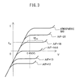
- the thus configured air-fuel ratio sensors 40 and 41 have the voltage-current (V-I) characteristic such as shown in FIG. 3 .
- V-I voltage-current
- the limit current region there is a region parallel to the sensor applied voltage V axis, that is, a region where the output current I does not change much at all even if the sensor applied voltage V changes. This voltage region is called the "limit current region”.
- the current at this time is called the "limit current”.
- the limit current region and limit current when the exhaust air-fuel ratio is 18 are shown by W 18 and I 18 .
- the output current rises substantially proportionally along with the rise of the sensor applied voltage.
- a region is called a "proportional region".
- the slope at this time is determined by the DC element resistance of the solid electrolyte layer 51.
- the output current also increases along with the increase in the sensor applied voltage. In this region, the output voltage changes according to the change in sensor applied voltage due to the breakdown of moisture contained in the exhaust gas at the exhaust side electrode 52 etc.
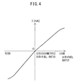
- FIG. 4 shows the relationship between the exhaust air-fuel ratio and the output current I when making the applied voltage V constant at about 0.45V ( FIG. 3 ).
- the output current changes linearly (proportionally) changes with respect to the exhaust air-fuel ratio so that the higher (that is, the leaner) the exhaust air-fuel ratio, the greater the output current I from the air-fuel ratio sensors 40 and 41.
- the air-fuel ratio sensors 40 and 41 are configured so that the output current I becomes zero when the exhaust air-fuel ratio is the stoichiometric air-fuel ratio.
- the air-fuel ratio sensors 40 and 41 instead of the limit current type air-fuel ratio sensor having the structure shown in FIG. 2 , it is also possible to use a layered-type limit current type air-fuel ratio sensor.
- the amount of fuel injection from the fuel injector 11 is set based on the outputs of the upstream side air-fuel ratio sensor 40 and the downstream side air-fuel ratio sensor 41 so that the air-fuel ratio of the exhaust gas flowing into the upstream side exhaust purification catalyst 20 becomes the optimal air-fuel ratio based on the engine operating state.
- the method may be mentioned of controlling the air-fuel ratio of the exhaust gas flowing into the upstream side exhaust purification catalyst 20 (or the target air-fuel ratio of the exhaust gas flowing out from the engine body) by feedback based on the output of the upstream side air-fuel ratio sensor 40 to become the target air-fuel ratio and correcting the output of the upstream side air-fuel ratio sensor 40 or changing the target air-fuel ratio etc. based on the output of the downstream side air-fuel ratio sensor 41.
- FIG. 5 is a time chart of the oxygen storage amount of the upstream side exhaust purification catalyst, the target air-fuel ratio, the output air-fuel ratio of the upstream side air-fuel ratio sensor, and the output air-fuel ratio of the downstream side air-fuel ratio sensor at the time of normal operation of the internal combustion engine.
- the "output air-fuel ratio” means the air-fuel ratio corresponding to the output of the air-fuel ratio sensor.
- "at the time of normal operation” means the operating state (control state) when not performing control for adjusting the amount of fuel injection corresponding to a specific operating state of the internal combustion engine (for example, control for increasing the amount of fuel injection at the time of acceleration of a vehicle mounting an internal combustion engine or fuel cut control for stopping the feed of fuel to a combustion chamber etc.
- the target air-fuel ratio is set to and maintained at a lean set air-fuel ratio AFTlean (for example, 15).
- the oxygen storage amount of the upstream side exhaust purification catalyst 20 is estimated.
- this estimated value becomes a predetermined judged reference storage amount Cref (amount smaller than maximum oxygen storage amount Cmax) or more, the target air-fuel ratio is set to and maintained at a rich set air-fuel ratio AFTrich (for example, 14.4). In the example shown in FIG. 5 , such an operation is repeated.
- the target air-fuel ratio is made a rich set air-fuel ratio AFTrich.
- the output air-fuel ratio of the upstream side air-fuel ratio sensor 40 also becomes an air-fuel ratio richer than the stoichiometric air-fuel ratio (below, "rich air-fuel ratio").
- the upstream side exhaust purification catalyst 20 stores oxygen, therefore the output air-fuel ratio of the downstream side air-fuel ratio sensor 41 becomes a substantially stoichiometric air-fuel ratio (14.6).
- the air-fuel ratio of the exhaust gas flowing into the upstream side exhaust purification catalyst 20 becomes a rich air-fuel ratio; therefore the oxygen storage amount of the upstream side exhaust purification catalyst 20 gradually falls.
- the oxygen storage amount of the upstream side exhaust purification catalyst 20 approaching zero part of the unburned gas (unburned HC and CO) flowing into the upstream side exhaust purification catalyst 20 starts to flow out without being removed by the upstream side exhaust purification catalyst 20.
- the output air-fuel ratio of the downstream side air-fuel ratio sensor 41 becomes a rich judged air-fuel ratio AFrich slightly richer than the stoichiometric air-fuel ratio.
- the target air-fuel ratio is switched from a rich set air-fuel ratio AFTrich to a lean set air-fuel ratio AFTlean.
- the air-fuel ratio of the exhaust gas flowing into the upstream side exhaust purification catalyst 20 becomes an air-fuel ratio leaner than the stoichiometric air-fuel ratio (below, referred to as "lean air-fuel ratio") and the outflow of unburned gas decreases and stops.
- the oxygen storage amount of the upstream side exhaust purification catalyst 20b gradually increases and, at the time t 3 , reaches a judged reference storage amount Cref. In this way when the oxygen storage amount reaches a judged reference storage amount Cref, the target air-fuel ratio is again switched from a lean set air-fuel ratio AFlean to a rich set air-fuel ratio AFTrich.
- the air-fuel ratio of the exhaust gas flowing into the upstream side exhaust purification catalyst 20 again becomes a rich air-fuel ratio.
- the oxygen storage amount of the upstream side exhaust purification catalyst 20 gradually decreases. Afterward, such an operation is repeatedly performed. By performing such control, it is possible to prevent outflow of NO X from the upstream side exhaust purification catalyst 20.
- control of the target air-fuel ratio based on the outputs of the upstream side air-fuel ratio sensor 40 and the downstream side air-fuel ratio sensor 41 performed as normal control is not limited to the above-mentioned such control. So long as control based on output of these air-fuel ratio sensors 40 and 41, any control is possible. Therefore, for example, as normal control, it is also possible to fix the target air-fuel ratio at the stoichiometric air-fuel ratio, control the output air-fuel ratio of the upstream side air-fuel ratio sensor 40 by feedback to become the stoichiometric air-fuel ratio, and correct the output air-fuel ratio of the upstream side air-fuel ratio sensor 40 based on the output air-fuel ratio of the downstream side air-fuel ratio sensor 41.
- FIG. 6 shows the relationship between the exhaust air-fuel ratio and the output current of an air-fuel ratio sensor 40 or 41 in the case where the air-fuel ratio sensor 40 or 41 is normal and the case where it is abnormal.
- the broken line in FIG. 6 shows the relationship in the case where the air-fuel ratio sensor 40 or 41 is not abnormal.
- the solid line in FIG. 6 shows the case where the air-fuel ratio sensor 40 or 41 is abnormal.
- the slope of the output current I to the exhaust air-fuel ratio in the example shown in FIG. 6 by Y becomes a value larger than the slope at a normal air-fuel ratio sensor 40 or 41. Therefore, in this case, the absolute value of the output current of an air-fuel ratio sensor 40 or 41 indicates a rich degree or lean degree larger (or smaller) than the rich degree or lean degree of the actual air-fuel ratio.
- the upstream side air-fuel ratio sensor 40 can accurately detect if the air-fuel ratio of the exhaust gas flowing into the upstream side exhaust purification catalyst 20 is a rich air-fuel ratio or a lean air-fuel ratio. This is because if the target air-fuel ratio is a rich air-fuel ratio, but the actual air-fuel ratio of the exhaust gas flowing into the upstream side exhaust purification catalyst 20 is a lean air-fuel ratio, the normal control such as shown in FIG. 5 no longer works.
- the downstream side air-fuel ratio sensor 41 can detect if the air-fuel ratio of the exhaust gas flowing out from the upstream side exhaust purification catalyst 20 is near the stoichiometric air-fuel ratio or is a rich air-fuel ratio or lean air-fuel ratio. This is because regardless of the actual air-fuel ratio of the exhaust gas flowing out from the upstream side exhaust purification catalyst 20 being the stoichiometric air-fuel ratio, if the air-fuel ratio detected by the downstream side air-fuel ratio sensor 41 becomes a rich air-fuel ratio, the normal control such as shown in FIG. 5 no longer works.
- FIG. 7 shows the relationship the voltage V applied to the air-fuel ratio sensor 40 or 41 and the output current I in the state where atmospheric gas circulates around the air-fuel ratio sensor 40 or 41 (that is, the state where exhaust gas of an air-fuel ratio corresponding to the atmospheric gas circulates).
- the solid line shows the relationship in the case where a circuit of the applied voltage control device 60 or current detecting part 61 etc. of the air-fuel ratio sensor 40 or 41 has become abnormal.
- the broken line shows the relationship in the case where the air-fuel ratio sensor 40 or 41 does not become abnormal, that is, the normal case.
- the output current I at the time when the air-fuel ratio sensor 40 or 41 is abnormal rises from the output current I at the time when it is normal by exactly a constant value.
- the limit current region Wlc indicates the limit current region which is formed in the state where atmospheric gas circulates around the air-fuel ratio sensor 40 or 41 when the air-fuel ratio sensor 40 or 41 is not abnormal in any way.
- the proportional region Wip indicates a proportional region which is formed in the state where atmospheric gas circulates around the air-fuel ratio sensor 40 or 41 when the air-fuel ratio sensor 40 or 41 is not abnormal in any way.
- the output current I rises compared with the normal case both if a voltage V applied to the air-fuel ratio sensor 40 or 41 is a voltage inside the limit current region Wlc or is a voltage inside the proportional region Wip. Note that, in the illustrated example, the example is shown where the output current I rises due to an abnormality in a circuit etc. of the air-fuel ratio sensor 40 or 41, but sometimes abnormality of a circuit etc. of the air-fuel ratio sensor 40 or 41 causes the output current I to fall over the entire region.
- the output current I of the air-fuel ratio sensor 40 or 41 always becomes a value deviated from the inherent value by a constant value.
- the output current I deviates from a suitable value to a smaller value in the entire region of the exhaust air-fuel ratio, that is, offset type deviation occurs.
- FIG. 8 also shows the relationship between the voltage V applied to the air-fuel ratio sensor 40 or 41 and the output current I in the state where atmospheric gas is circulating around the air-fuel ratio sensor 40 or 41.
- the solid line in the figure shows the relationship in the case where the diffusion regulation layer 54 of the air-fuel ratio sensor 40 or 41 becomes partially clogged or cracked or otherwise abnormal, or the case where an electrode 52 or 53 of the air-fuel ratio sensor 40 or 41 deteriorates or otherwise becomes abnormal.
- the broken line in the figure shows the relationship in the case where the air-fuel ratio sensor 40 or 41 does not become abnormal.
- the output current I at the time when the air-fuel ratio sensor 40 or 41 becomes abnormal and the output current I at the time when it is normal become substantially the same value.
- the case is shown where abnormality of the diffusion regulation layer 54 or electrode 52 or 53 etc. of the air-fuel ratio sensor 40 or 41 causes the output current I to rise, but sometimes abnormality of the diffusion regulation layer 54 or electrode 52 or 53 etc. of the air-fuel ratio sensor 40 or 41 also causes the output current I to fall.
- the slope at the V-I graph at this time is determined in accordance with the DC element resistance of the solid electrolyte layer 51.
- the amount of unburned gas or oxygen passing through the diffusion regulation layer 54 and reaching the electrode 52 is smaller than the amount of oxygen ions able to pass through the solid electrolyte layer 51 per unit time.
- the amount of oxygen ions moving through the solid electrolyte layer 51 remains constant as the amount of flow of unburned gas or oxygen passing through the diffusion regulation layer 54 and reaching the electrode 52.
- the amount of oxygen ions moving through the inside of the solid electrolyte layer 51 does not change and therefore the output current I also does not change.
- the amount of flow of the unburned gas or oxygen reaching an electrode through the diffusion regulation layer 54 changes.
- the output current I is determined by the amount of flow of the unburned gas or oxygen passing through the diffusion regulation layer 54 and reaching the electrode 52, and therefore the output current I changes.
- the amount of oxygen ions which can move through the inside of the solid electrolyte layer 51 per unit time is greater than the amount of flow of the unburned gas or oxygen passing through the diffusion regulation layer 54 and reaching the electrode 52. As a result, even if the diffusion regulation layer 54 is clogged or cracked etc. the output current I inside the proportional region does not change.
- the diffusion regulation layer 54 is clogged or cracked etc. compared with when this does not arise, the extent by which the output current I changes becomes greater the larger the difference of the exhaust air-fuel ratio from the stoichiometric air-fuel ratio. This is because the larger the difference of the exhaust air-fuel ratio from the stoichiometric air-fuel ratio, the greater the amount of oxygen or unburned gas included in the unit exhaust gas, therefore the more the amount of unburned gas or oxygen reaching the electrode 52 changes if the amount of exhaust gas passing through the diffusion regulation layer 54 changes. As a result, if the diffusion regulation layer 54 or electrode 52 or 53 etc. of an air-fuel ratio sensor 40 or 41 becomes abnormal, a slope type deviation such as shown in FIG. 6 by Y occurs.
- FIG. 9 shows the relationship between the voltage V applied to an air-fuel ratio sensor 40 or 41 and the output current I in the state where atmospheric gas is circulating around the air-fuel ratio sensor 40 or 41.
- the solid line shows the relationship in the case where the air-fuel ratio sensor 40 or 41 has a cracked element or is otherwise abnormal.
- a "cracked element" of the air-fuel ratio sensor 40 or 41 specifically means a crack passing through the solid electrolyte layer 51 and diffusion regulation layer 54 ( FIG. 10 , C1) or a crack passing through not only the solid electrolyte layer 51 and diffusion regulation layer 54, but also the two electrodes 52 and 53 ( FIG. 10 , C2).
- the broken line shows the relationship in the case where the air-fuel ratio sensor 40 or 41 is not abnormal. If the air-fuel ratio sensor 40 or 41 has a cracked element, the reference gas in the reference gas chamber 55 (usually, atmospheric gas) becomes abnormal (abnormality of reference gas).
- Table 1 Rise in output current inside proportional region No change in output current inside proportional region Fall in output current inside proportional region Rise in output current inside limit current region Offset type deviation Slope type deviation - No change in output current inside limit current region Abnormality of reference gas Normal Abnormality of reference gas Fall in output current inside limit current region output - Slope type deviation Offset type deviation
- an abnormality diagnosis system of an air-fuel ratio sensor provided in an exhaust passage of an internal combustion engine and generating a limit current corresponding to an air-fuel ratio
- the system comprises a current detecting part 61 detecting an output current I of an air-fuel ratio sensor 40 or 41 and an applied voltage control device 60 controlling a voltage applied to the air-fuel ratio sensor 40 or 41
- the system applies a voltage inside a limit current region where a limit current is generated and a voltage outside the limit current region (in particular, a proportional region) to the air-fuel ratio sensor 40 or 41 when the air-fuel ratio of the exhaust gas circulating around the air-fuel ratio sensor 40 or 41 is made a predetermined constant air-fuel ratio, and judges a type of abnormality occurring at the air-fuel ratio sensor 40 or 41 based on an output current I of the air-fuel ratio sensor 40 or 41 detected by the current detecting part at this time.
- the voltage inside the limit current region and the voltage outside the limit current region are applied, for example, by changing the voltage applied to the air-fuel ratio sensor 40 or 41 by the applied voltage control device 60 in the state maintaining the air-fuel ratio of the exhaust gas circulating around the air-fuel ratio sensor 40 or 41 at a constant air-fuel ratio.
- the output currents when applying a voltage inside the limit current region and when applying a voltage outside the limit current region to the air-fuel ratio sensor 40 or 41 in the state where the air-fuel ratio of the exhaust gas circulating around the air-fuel ratio sensor 40 or 41 is maintained at a predetermined constant air-fuel ratio are respectively detected or calculated in advance as a normal value inside the limit current region and a normal value outside the limit current region, and the type of abnormality occurring at the air-fuel ratio sensor 40 or 41 is judged based on the difference between the detected value of the output current of the air-fuel ratio sensor 40 or 41 when applying a voltage inside the limit current region to the air-fuel ratio sensor 40 or 41 in the state where the air-fuel ratio of the exhaust gas circulating around the air-fuel ratio sensor 40 or 41 is maintained at the predetermined constant air-fuel ratio and the normal value inside the limit current region ,and the difference between the detected value of the output current of the air-fuel ratio sensor 40 or 41 when applying the
- the diagnosis of abnormality of an air-fuel ratio sensor in the present embodiment will be explained using as an example the case of diagnosing abnormality of the downstream side air-fuel ratio sensor 41.
- the target air-fuel ratio is alternately changed between a rich set air-fuel ratio AFTrich and a lean set air-fuel ratio AFTlean.
- Such control alternately changing the target air-fuel ratio between the rich set air-fuel ratio AFTrich and the lean set air-fuel ratio AFTlean will be called "normal control".
- the feed of fuel from a fuel injector 11 to a combustion chamber 5 is stopped as fuel cut control.
- the oxygen storage amount of the exhaust purification catalyst 20 or 24 reaches the maximum storable amount of oxygen. For this reason, to release the oxygen stored in the exhaust purification catalyst 20 or 24 after the end of fuel cut control, the target air-fuel ratio is made richer than the rich set air-fuel ratio AFTrich at the time of the above-mentioned normal control as post-reset rich control.
- the downstream side air-fuel ratio sensor 41 is diagnosed for abnormality in the present embodiment when the air-fuel ratio of the exhaust gas around the downstream side air-fuel ratio sensor 41 is maintained at a constant air-fuel ratio.
- abnormality is diagnosed during fuel cut control where the air-fuel ratio of the exhaust gas around the downstream side air-fuel ratio sensor 41 is maintained at an air-fuel ratio corresponding to the atmospheric gas.
- abnormality is diagnosed also during post-reset rich control where the air-fuel ratio of the exhaust gas around the downstream side air-fuel ratio sensor 41 becomes substantially the stoichiometric air-fuel ratio.
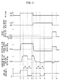
- FIG. 11 is a time chart of the presence of these fuel cut control and post-reset rich control, the target air-fuel ratio, the output air-fuel ratio of the upstream side air-fuel ratio sensor 40, the output air-fuel ratio of the downstream side air-fuel ratio sensor 41, and the voltage applied to the downstream side air-fuel ratio sensor 41.
- the target air-fuel ratio is the rich set air-fuel ratio AFTrich at the time of normal control alternately changing the target air-fuel ratio between the rich air-fuel ratio and the lean air-fuel ratio.
- the output air-fuel ratio of the upstream side air-fuel ratio sensor 40 becomes a rich air-fuel ratio.
- the unburned gas in the exhaust gas flowing into the upstream side exhaust purification catalyst 20 is removed by the upstream side exhaust purification catalyst 20, therefore the output air-fuel ratio of the downstream side air-fuel ratio sensor 41 becomes the stoichiometric air-fuel ratio.
- the output air-fuel ratio AFup of the upstream side air-fuel ratio sensor 40 changes to a lean air-fuel ratio with an extremely large lean degree corresponding to atmospheric gas. Further, atmospheric gas also flows into the upstream side exhaust purification catalyst 20, but the oxygen in the atmospheric gas flowing into the upstream side exhaust purification catalyst 20 is stored in the upstream side exhaust purification catalyst 20. For this reason, right after the start of the fuel cut control, the output air-fuel ratio of the downstream side air-fuel ratio sensor 41 is maintained at substantially the stoichiometric air-fuel ratio.
- the oxygen storage amount of the upstream side exhaust purification catalyst 20 immediately reaches the maximum storable amount of oxygen, and atmospheric gas flows out from the upstream side exhaust purification catalyst 20.
- the output air-fuel ratio of the downstream side air-fuel ratio sensor 41 also changes to a lean air-fuel ratio with an extremely large lean degree corresponding to the atmospheric gas.
- the voltage V applied to the downstream side air-fuel ratio sensor 41 is made to rise to a second voltage V 2 (for example, 1.0V).
- V 2 is the voltage in the limit current region Wlc formed in the state where atmospheric gas circulates around the downstream side air-fuel ratio sensor 41 in the case where the downstream side air-fuel ratio sensor 41 is not abnormal.
- the output air-fuel ratio of the downstream side air-fuel ratio sensor 41 stops rising and converges to a constant value.
- the diagnosis of abnormality is started at the time t 2 when the output air-fuel ratio of the downstream side air-fuel ratio sensor 41 settles down, and the voltage applied to the downstream side air-fuel ratio sensor 41 is maintained constant over a predetermined constant time ⁇ t from the time t 2 .
- the voltage V applied to the downstream side air-fuel ratio sensor 41 is lowered to a first voltage V 1 (for example, 0.2V).
- the first voltage V 1 is the voltage inside the proportional region Wip formed in the state where atmospheric gas circulates around the downstream side air-fuel ratio sensor 41 when the downstream side air-fuel ratio sensor 41 is not abnormal.
- the voltage applied to the downstream side air-fuel ratio sensor 41 is maintained constant over a predetermined constant time ⁇ t from the time t 3 when the voltage V applied to the downstream side air-fuel ratio sensor 41 is changed to the first voltage V 1 .
- the voltage applied to the downstream side air-fuel ratio sensor 41 is made to rise to the voltage for normal control (for example, 0.45V).
- the fuel cut control is made to end at the time t 5 .
- the target air-fuel ratio is made a post-reset rich set air-fuel ratio AFTrt richer than the rich set air-fuel ratio AFTrich. If the target air-fuel ratio becomes the post-reset rich set air-fuel ratio, along with this, the output air-fuel ratio of the upstream side air-fuel ratio sensor 40 also changes to an air-fuel ratio corresponding to the post-reset rich set air-fuel ratio AFTrt.
- exhaust gas of a rich air-fuel ratio flows into the upstream side exhaust purification catalyst 20 as well, but the unburned gas in the exhaust gas flowing into the upstream side exhaust purification catalyst 20 reacts with the oxygen stored in the upstream side exhaust purification catalyst 20 to be removed.
- the output air-fuel ratio of the downstream side air-fuel ratio sensor 41 is decreased if post-reset rich control is started at the time t 5 and finally becomes substantially the stoichiometric air-fuel ratio.
- the voltage V applied to the downstream side air-fuel ratio sensor 41 is made a fourth voltage V 4 (for example, 0.45V).
- the fourth voltage V 4 is the voltage inside the limit current region formed in the state where exhaust gas of the stoichiometric air-fuel ratio circulates around the downstream side air-fuel ratio sensor 41 when the downstream side air-fuel ratio sensor 41 is not abnormal.
- the output air-fuel ratio of the downstream side air-fuel ratio sensor 41 finishes falling and converges to a constant value.
- the voltage applied to the downstream side air-fuel ratio sensor 41 is maintained constant over a predetermined constant time ⁇ t from the time t 6 at which the output air-fuel ratio of the downstream side air-fuel ratio sensor 41 settles down.
- the voltage V applied to the downstream side air-fuel ratio sensor 41 is made to fall to a third applied voltage V 3 (for example, 0.1V) at the time t 7 after a predetermined constant time ⁇ t elapses from the time t 6 .
- the third voltage V 3 is a voltage inside the proportional region formed in the state where exhaust gas of the stoichiometric air-fuel ratio circulates around the downstream side air-fuel ratio sensor 41 when the downstream side air-fuel ratio sensor 41 is not abnormal.
- the voltage applied to the downstream side air-fuel ratio sensor 41 is maintained constant over a predetermined constant time ⁇ t from the time t 7 at which the voltage V applied to the downstream side air-fuel ratio sensor 41 is changed to the third voltage V 3 .
- the diagnosis of abnormality is ended. Therefore, at the time t 8 , the voltage applied to the downstream side air-fuel ratio sensor 41 is made to rise to the normal control voltage (for example, 0.45V). Further, in the example shown in FIG. 11 , even at the time t 8 , the post-reset rich control has not ended, therefore the target air-fuel ratio is maintained at the post-reset rich set air-fuel ratio AFTrt. Due to this, the output air-fuel ratio of the upstream side air-fuel ratio sensor 40 is made the rich air-fuel ratio, and the oxygen storage amount of the upstream side exhaust purification catalyst 20 is gradually decreased.
- the normal control voltage for example 0.45V
- the oxygen storage amount of the upstream side exhaust purification catalyst 20 is gradually decreased and finally becomes substantially zero, and exhaust gas of a rich air-fuel ratio starts to flow out from the upstream side exhaust purification catalyst 20. Due to this, at the time t 9 , the output air-fuel ratio of the downstream side air-fuel ratio sensor 41 becomes the rich judged air-fuel ratio AFrich or less. In the present embodiment, in this way, if the output air-fuel ratio of the downstream side air-fuel ratio sensor 41 becomes the rich judged air-fuel ratio AFrich or less, post-reset rich control is made to end and the normal control shown in FIG. 5 is resumed.
- the output current at the time when the voltage V applied to the downstream side air-fuel ratio sensor 41 in the state where the exhaust air-fuel ratio around the downstream side air-fuel ratio sensor 41 is an air-fuel ratio corresponding to atmospheric gas is a voltage V 2 inside the limit current region Wlc is detected or calculated in advance experimentally or by computation as a normal value.
- the output current when the voltage V applied to the downstream side air-fuel ratio sensor 41 in the state where the exhaust air-fuel ratio around the downstream side air-fuel ratio sensor 41 is an air-fuel ratio corresponding to atmospheric gas is a voltage V 1 inside the proportional region Wip is detected or calculated in advance experimentally or by computation as a normal value.
- the downstream side air-fuel ratio sensor 41 when performing control such as shown in FIG. 11 , if the downstream side air-fuel ratio sensor 41 is normal, as explained above, the detected value of the output current I by the current detecting part 61 in the state applying a voltage V 2 inside a limit current region to the downstream side air-fuel ratio sensor 41 substantially matches the normal value in such a state (normal value inside the limit current region). Similarly, when the downstream side air-fuel ratio sensor 41 is normal, as explained above, the detected value of the output current I by the current detecting part 61 in the state applying a voltage V 1 inside the proportional region to the downstream side air-fuel ratio sensor 41 substantially matches the normal value in such a state (normal value outside the limit current region).
- the downstream side air-fuel ratio sensor 41 when the detected value of the output current I of the downstream side air-fuel ratio sensor 41 at the times t 2 to t 3 substantially matches the corresponding normal value inside a limit current region and the detected value of the output current I of the downstream side air-fuel ratio sensor 41 at the times t 3 to t 4 substantially matches the corresponding normal value outside the limit current region, it is judged the downstream side air-fuel ratio sensor 41 is normal.
- the detected value of the output current I by the current detecting part 61 in the state applying a voltage V 2 inside the limit current region to the downstream side air-fuel ratio sensor 41 becomes a value whereby the difference from the corresponding normal value inside the limit current region becomes a predetermined reference value (reference value inside the limit current region) or more.
- the detected value of the output current I by the current detecting part 61 in the state applying a voltage V 1 inside the proportional region to the downstream side air-fuel ratio sensor 41 becomes a value whereby the difference from the corresponding normal value outside the limit current region becomes a predetermined reference value (reference value outside the limit current region) or more.
- the difference between the detected value of the output current I of the downstream side air-fuel ratio sensor 41 at the times t 2 to t 3 and the corresponding normal value inside the limit current region is the reference value or more and the difference between the detected value of the output current I of the downstream side air-fuel ratio sensor 41 at the times t 3 to t 4 and the corresponding normal value outside the limit current region is the reference value or more, it is judged that offset type deviation has occurred at the downstream side air-fuel ratio sensor 41.
- the diffusion regulation layer 54 or electrode 52 etc. of the downstream side air-fuel ratio sensor 41 becomes abnormal, that is, if the downstream side air-fuel ratio sensor 41 suffers from a slope type deviation, as explained above, the detected value of the output current I by the current detecting part 61 in the state applying a voltage V 2 inside the limit current region to the downstream side air-fuel ratio sensor 41 becomes a value whereby the difference from the corresponding normal value inside the limit current region becomes a predetermined reference value (reference value inside the limit current region) or more.
- the downstream side air-fuel ratio sensor 41 suffers from a slope type deviation, as explained above, the detected value of the output current I by the current detecting part 61 in the state applying a voltage V 1 inside the proportional region to the downstream side air-fuel ratio sensor 41 substantially matches the corresponding normal value outside the limit current region.
- the downstream side air-fuel ratio sensor 41 when the difference between the detected value of the output current I of the downstream side air-fuel ratio sensor 41 at the times t 2 to t 3 and the corresponding normal value inside the limit current region is the reference value or more and the detected value of the output current I of the downstream side air-fuel ratio sensor 41 at the times t 3 to t 4 substantially matches the corresponding normal value outside the limit current region, it is judged that the downstream side air-fuel ratio sensor 41 suffers from slope type deviation.
- the downstream side air-fuel ratio sensor 41 has a cracked element or is otherwise abnormal, that is, when the downstream side air-fuel ratio sensor 41 has an abnormality of the reference gas, as explained above, the detected value of the output current I by the current detecting part 61 in the state applying a voltage V 2 inside the limit current region to the downstream side air-fuel ratio sensor 41 substantially matches the corresponding normal value inside the limit current region.
- the downstream side air-fuel ratio sensor 41 suffers from a slope type deviation, as explained above, the detected value of the output current I by the current detecting part 61 in the state applying a voltage V 1 inside the proportional region to the downstream side air-fuel ratio sensor 41 becomes a value whereby the difference from the corresponding normal value outside the limit current region becomes a predetermined reference value (reference value outside the limit current region) or more.
- the downstream side air-fuel ratio sensor 41 at the times t 2 to t 3 substantially matches the corresponding normal value inside the limit current region and the difference between the detected value of the output current I of the downstream side air-fuel ratio sensor 41 at the times t 3 to t 4 and the corresponding normal value outside the limit current region is the reference value or more, it is judged that the downstream side air-fuel ratio sensor 41 suffers from an abnormality of the reference gas.
- the downstream side air-fuel ratio sensor 41 when the downstream side air-fuel ratio sensor 41 is normal, in the state where the exhaust air-fuel ratio around the downstream side air-fuel ratio sensor 41 is the stoichiometric air-fuel ratio, the output current when the voltage V applied to the downstream side air-fuel ratio sensor 41 is a voltage V 3 inside the proportional region Wip is detected or calculated in advance experimentally or by computation as a normal value outside the limit current region.
- the difference between the detected value of the output current I by the current detecting part 61 in the state applying a voltage V 4 inside the limit current region to the downstream side air-fuel ratio sensor 41 and the corresponding normal value inside the limit current region is calculated.
- the difference of the detected value of the output current I by the current detecting part 61 in the state applying a voltage V 3 inside the proportional region to the downstream side air-fuel ratio sensor 41 and the corresponding normal value outside the limit current region is calculated. Based on the difference of the output current I calculated in this way, the same technique as in the case of the above-mentioned times t 2 to t 4 is used to diagnose the mode of abnormality of the downstream side air-fuel ratio sensor 41.
- diagnosis of abnormality is performed two times.
- the downstream side air-fuel ratio sensor 41 may be diagnosed for abnormality at just one of these.
- the diagnosis of abnormality of the downstream side air-fuel ratio sensor 41 was used as an example for the explanation, but the upstream side air-fuel ratio sensor 40 can also be similarly diagnosed for abnormality.
- exhaust gas before flowing into the upstream side exhaust purification catalyst 20 circulates around the upstream side air-fuel ratio sensor 40. Therefore, during post-reset rich control, what kind of air-fuel ratio the air-fuel ratio of the exhaust gas circulating around the upstream side air-fuel ratio sensor 40 becomes is unknown. For this reason, the upstream side air-fuel ratio sensor 40 is not diagnosed for abnormality during post-reset rich control.
- the above embodiment applies one voltage inside the limit current region and one voltage inside the proportional region to the downstream side air-fuel ratio sensor 41 and judges the type of abnormality of an air-fuel ratio sensor 40 or 41 based on the output current I of the air-fuel ratio sensor 40 or 41 at this time.
- inside the limit current region basically, even if the applied voltage V changes, the output current I does not change, but inside the proportional region, if the applied voltage V changes, the output current I also changes.
- the number of times of application of different voltage inside the proportional region is preferably greater than the number of times of application of different voltage in the limit current region.
- the present embodiment by detecting the output current of an air-fuel ratio sensor in the state applying a voltage inside the limit current region and a voltage inside the proportional region to the air-fuel ratio sensor 40 or 41, it is possible to differentiate the different modes of abnormality in particular as abnormalities due to offset type deviation and abnormalities due to other causes.
- FIG. 12 shows a flow chart of the control routine for diagnosis of abnormality of the downstream side air-fuel ratio sensor 41.
- FIG. 12 shows a flow chart in the case of diagnosing abnormality during fuel cut control, that is, in the case of diagnosing abnormality at the times t 2 to t 4 of FIG. 11 .
- the illustrated control routine is performed by interruption at every constant time interval.
- step S11 it is judged if the condition for diagnosis of abnormality stands.
- the case where the condition for diagnosis of abnormality stands is, for example, when the temperature of the downstream side air-fuel ratio sensor 41 becomes the active temperature or more and the diagnosis of the downstream side air-fuel ratio sensor 41 for abnormality has not yet finished after the internal combustion engine has been started up or the ignition key of the vehicle mounting the internal combustion engine has been turned on. If at step S11 it is judged that the condition for diagnosis of abnormality does not stand, the routine proceeds to step S12. At step S12, the later explained number of times "i" of application of different voltage is reset to 1, the output currents I(1) to I(n) at the time of the first to n-th applications of voltage are reset to 0, and the control routine is made to end.
- step S11 determines whether the condition for diagnosis of abnormality stands. If at step S11 it is judged that the condition for diagnosis of abnormality stands, the routine proceeds to step S13. At step S13, it is judged if fuel cut control (FC) is underway. If at step S13 it is judged fuel cut control is not underway, the routine proceeds to step S12 where the number of times "i" of application of voltage is reset to 1, the output currents at the time of the first to n-th applications of voltage are reset to 0, and the control routine is made to end.
- FC fuel cut control
- step S14 the voltage V applied to the downstream side air-fuel ratio sensor 41 is made the i-th applied voltage V(i).
- the i-th applied voltage V(i) is set in advance.
- the first applied voltage V(1) is made a voltage inside the limit current region occurring in a state where atmospheric gas circulates around an air-fuel ratio sensor 40 or 41 in the case where no abnormality occurs in the air-fuel ratio sensor 40 or 41.
- the second applied voltage V(2) is made a voltage inside the proportional region formed in the state where atmospheric gas circulates around the air-fuel ratio sensor 40 or 41 in the case where no abnormality occurs at the air-fuel ratio sensor 40 or 41.
- the number of times "i" of application of different voltage and the i-th applied voltage V(i) may be set to any number and voltage if applying a voltage inside the limit current region at least one time and applying a voltage inside the proportional region at least one time.
- step S12 the number of times "i" of application of the voltage is set to 1 by step S12. Therefore, right after the start of fuel cut control, at step S14, the number of times "i" of application of the voltage is set to 1. For this reason, right after the start of fuel cut control, the applied voltage V is made the first applied voltage V(1), for example, is made a voltage V 2 inside the limit current region.
- step S15 it is judged if the output current I of the downstream side air-fuel ratio sensor 41 has stabilized.
- Whether the output current I of the downstream side air-fuel ratio sensor 41 has stabilized is judged based on, for example, whether the amount of change of the output current I of the downstream side air-fuel ratio sensor 41 per unit time has become a constant amount or less. Alternatively, whether the output current I of the downstream side air-fuel ratio sensor 41 has stabilized may be judged based on whether the time elapsed from changing the applied voltage V is a predetermined time or more.
- step S15 it is judged that the output current I of the downstream side air-fuel ratio sensor 41 has not stabilized
- the routine proceeds from step S15 to step S16.
- step S16 it is judged that the elapsed time from when it is judged at step S15 that the output current I of the downstream side air-fuel ratio sensor 41 has stabilized is a predetermined constant time ⁇ t or more.
- step S16 it is judged that the elapsed time is shorter than the constant time ⁇ t, the control routine is made to end.
- step S17 the average value of the output current I of the downstream side air-fuel ratio sensor 41 from when it is judged that the output current I of the downstream side air-fuel ratio sensor 41 has stabilized to when the constant time ⁇ t has elapsed is calculated, then this average value is made the output current I(i) when applying the i-th applied voltage V(i). Therefore, when the first applied voltage V(1) is applied, the output current I(1) when applying the first applied voltage V(1) is calculated.
- step S18 it is judged if the number of times "i" of application of different voltage is "n" times or more. "n” is made a value of 2 or more.
- the routine proceeds to step S19.
- step S19 the number of times "i" of application of different voltage is incremented by 1, then the control routine is made to end.
- step S14 the applied voltage V is made the second applied voltage V(2). After that, if it is judged if the elapsed time from when it is judged the output current I of the downstream side air-fuel ratio sensor 41 has stabilized after the applied voltage V is made the second applied voltage V(2) has become the constant time ⁇ t or more, the routine proceeds again to step S17.
- step S17 the average value of the output current I of the downstream side air-fuel ratio sensor 41 from when it is judged that the output current I of the downstream side air-fuel ratio sensor 41 has stabilized to when a constant time ⁇ t elapses is calculated and this average value is made the output current I(2) when applying the second applied voltage V(2).
- step S18 it is judged if the number of times "i" of application of different voltage is "n" times or more.
- “n” is 2
- steps S11 to S17 are repeated until the number of times of application of different voltage becomes “n” times.
- step S20 based on the output currents I(0) to I(n) calculated at step S17, these are compared with the normal value as explained above and the mode of abnormality of the downstream side air-fuel ratio sensor 41 is judged.
- step S21 the number of times "i" of application of different voltage is reset to 1, the output currents at the times of the first to n-th applications of voltage are reset to 0, and the control routine is made to end.
- control routine shown in FIG. 12 shows the case of diagnosing abnormality during fuel cut control, but a similar control routine can be used for diagnosis of abnormality when diagnosing abnormality during post-reset rich control as well.
- step S13 it is judged not if fuel cut control is underway, but if post-reset rich control is underway. Further, in this case, the i-th applied voltage V(i) is also made a voltage different from the applied voltage in the case during fuel cut control.
- an abnormality diagnosis system according to a second embodiment of the present invention will be explained.
- the configuration and control in the abnormality diagnosis system according to second embodiment are basically the same as the configuration and control in the abnormality diagnosis system according to the first embodiment except for the parts explained below.
- the upstream side air-fuel ratio sensor 40 when the upstream side air-fuel ratio sensor 40 is not abnormal, if the output air-fuel ratio of the upstream side air-fuel ratio sensor 40 is controlled by feedback to become the target air-fuel ratio, the air-fuel ratio of the exhaust gas flowing into the upstream side exhaust purification catalyst 20 becomes an air-fuel ratio the same as the target air-fuel ratio. Therefore, if maintaining the target air-fuel ratio constant at the stoichiometric air-fuel ratio, the air-fuel ratio of the exhaust gas flowing into the upstream side exhaust purification catalyst 20 becomes the stoichiometric air-fuel ratio, and the air-fuel ratio of the exhaust gas circulating around the downstream side air-fuel ratio sensor 41 is also maintained constant at the stoichiometric air-fuel ratio.
- the air-fuel ratio of the exhaust gas circulating around the downstream side air-fuel ratio sensor 41 becomes substantially the stoichiometric air-fuel ratio.
- the oxygen storage amount of the upstream side exhaust purification catalyst 20 becomes zero, the unburned gas will no longer be removed at the upstream side exhaust purification catalyst 20.
- the air-fuel ratio of the exhaust gas circulating around the downstream side air-fuel ratio sensor 41 is maintained constant at the rich air-fuel ratio of the target air-fuel ratio.
- the downstream side air-fuel ratio sensor 41 is diagnosed for abnormality when the air-fuel ratio of the exhaust gas circulating around the downstream side air-fuel ratio sensor 41 is maintained at a predetermined constant air-fuel ratio by maintaining the target air-fuel ratio constant at a predetermined air-fuel ratio.
- FIG. 13 is a time chart of the abnormality diagnosis flag, the target air-fuel ratio, the output air-fuel ratio of the upstream side air-fuel ratio sensor 40, the output air-fuel ratio of the downstream side air-fuel ratio sensor 41, and voltage applied to the downstream side air-fuel ratio sensor 41.
- the target air-fuel ratio is alternately changed between the rich set air-fuel ratio AFTrich and the lean set air-fuel ratio AFTlean.
- the target air-fuel ratio becomes the rich set air-fuel ratio AFTrich at the time of normal control alternately changing the target air-fuel ratio between the rich air-fuel ratio and the lean air-fuel ratio.
- the target air-fuel ratio is changed from the rich set air-fuel ratio AFTrich to the stoichiometric air-fuel ratio (14.6).
- the output air-fuel ratio AFup of the upstream side air-fuel ratio sensor is changed to the stoichiometric air-fuel ratio.
- the output air-fuel ratio AFdwn of the downstream side air-fuel ratio sensor 41 is maintained at the stoichiometric air-fuel ratio.
- the voltage V applied to the downstream side air-fuel ratio sensor 41 is made a fourth voltage V 4 (for example, 0.45V).
- the fourth voltage V 4 is the voltage in the limit current region formed in the state where exhaust gas of a stoichiometric air-fuel ratio circulates around the downstream side air-fuel ratio sensor 41 when the downstream side air-fuel ratio sensor 41 is not abnormal.
- the voltage applied to the downstream side air-fuel ratio sensor 41 is maintained constant over a predetermined constant time ⁇ t from the time t 2 after the elapse of a predetermined time ⁇ t 0 from the time t 1 .
- the time ⁇ t 0 is made the time required for the output air-fuel ratio of the downstream side air-fuel ratio sensor 41 to converge at the stoichiometric air-fuel ratio as a result of the target air-fuel ratio being changed to the stoichiometric air-fuel ratio even if for example the output air-fuel ratio of the downstream side air-fuel ratio sensor 41 had become a rich air-fuel ratio at the time t 1 .
- the voltage V applied to the downstream side air-fuel ratio sensor 41 is lowered to a third voltage V 3 (for example, 0.1V).
- the third voltage V 3 is the voltage inside the proportional region Wip occurring in the state where exhaust gas of the stoichiometric air-fuel ratio circulates around the downstream side air-fuel ratio sensor 41 when the downstream side air-fuel ratio sensor 41 is not abnormal.
- the voltage applied to the downstream side air-fuel ratio sensor 41 is maintained constant over a predetermined constant time ⁇ t from the time t 3 when the voltage V applied to the downstream side air-fuel ratio sensor 41 is changed to the third voltage V 3 .
- the diagnosis of abnormality is ended at the time t 4 after a predetermined constant time ⁇ t elapses from the time t 3 . Therefore, at the time t 4 , the voltage applied to the downstream side air-fuel ratio sensor 41 is made to rise to the voltage for normal control (for example, 0.45V), and the target air-fuel ratio is returned to the rich set air-fuel ratio AFTrich, then the normal control shown in FIG. 5 is performed.
- the voltage for normal control for example, 0.45V
- the output current at the time when the voltage V applied to the downstream side air-fuel ratio sensor 41 in the state where the exhaust air-fuel ratio around the downstream side air-fuel ratio sensor 41 is the stoichiometric air-fuel ratio is a voltage V 4 inside the limit current region is detected or calculated in advance by experiments or by computation as the normal value inside the limit current region.
- the output current at the time when the voltage V applied to the downstream side air-fuel ratio sensor 41 in the state where the exhaust air-fuel ratio around the downstream side air-fuel ratio sensor 41 is the stoichiometric air-fuel ratio is a voltage V 3 inside the proportional region is detected or calculated in advance by experiments or by computation as the normal value outside the limit current region.
- the downstream side air-fuel ratio sensor 41 has an offset type deviation.
- the downstream side air-fuel ratio sensor 41 has a slope type deviation.
- the downstream side air-fuel ratio sensor 41 has an abnormality of the reference gas.
- FIG. 13 shows the case of maintaining the target air-fuel ratio constant at the stoichiometric air-fuel ratio, but the target air-fuel ratio may also be maintained at an air-fuel ratio other than the stoichiometric air-fuel ratio.
- the oxygen storage amount of the upstream side exhaust purification catalyst 20 has to reach the maximum storable amount of oxygen or zero before the air-fuel ratio of the exhaust gas circulating around the downstream side air-fuel ratio sensor 41 stabilizes. For this reason, the time required for the air-fuel ratio of the exhaust gas circulating around the downstream side air-fuel ratio sensor 41 to settle down, that is, the time ⁇ t 0 , is made a relatively long time.
- abnormality is diagnosed during fuel cut control or during post-reset rich control.
- fuel cut control and post-reset rich control are performed in accordance with the engine operating state. In some cases, they are not performed for a long period of time. For this reason, sometimes it is not possible to diagnose abnormality over a long period of time.
- the target air-fuel ratio in diagnosis of abnormality, is maintained at a predetermined constant air-fuel ratio.
- the target air-fuel ratio may also be switched between the rich air-fuel ratio and the lean air-fuel ratio alternately at short intervals. If alternately switching the target air-fuel ratio between the rich air-fuel ratio and the lean air-fuel ratio at short intervals in this way, the unburned gas and air in the exhaust gas are removed at the upstream side exhaust purification catalyst 20. For this reason, the air-fuel ratio of the exhaust gas circulating around the downstream side air-fuel ratio sensor 41 is maintained constant at the stoichiometric air-fuel ratio.
- the target air-fuel ratio has to be alternately changed between the rich air-fuel ratio and the lean air-fuel ratio so that the oxygen storage amount of the upstream side exhaust purification catalyst 20 is maintained at an amount greater than zero and smaller than the maximum storable amount of oxygen.
- FIG. 14 is a flow chart of the control routine for diagnosis of abnormality of the downstream side air-fuel ratio sensor 41.
- the illustrated control routine is performed by interruption at every constant time interval.
- step S31 it is judged if the condition for diagnosis of abnormality stands. If at step S31 it is judged if the condition for diagnosis of abnormality does not stand, the routine proceeds to step S32. At step S32, the number of times "i" of application of different voltage is reset to 1, the output currents I(0) to I(n) at the time of the first to n-th applications of voltage are reset to 0, then the control routine is made to end.
- step S32 determines whether the condition for diagnosis of abnormality stands. If at step S32 it is judged that the condition for diagnosis of abnormality stands, the routine proceeds to step S33.
- the target air-fuel ratio is made the stoichiometric air-fuel ratio (14.6).
- step S34 in the same way as step S14, the voltage V applied to the downstream side air-fuel ratio sensor 41 is made the i-th applied voltage V(i).
- step S35 it is judged if the number of times "i" of application of different voltage is 2 or more. When the number of times "i" of application is 1, the routine proceeds to step S36.
- step S36 it is judged if the elapsed time from when setting the target air-fuel ratio to the stoichiometric air-fuel ratio is the above-mentioned predetermined time ⁇ t 0 or more. If at step S36 it is judged that the elapsed time from when setting the target air-fuel ratio to the stoichiometric air-fuel ratio is less than the above-mentioned predetermined time ⁇ t 0 , that is, if it is judged that sometimes the air-fuel ratio of the exhaust gas circulating around the downstream side air-fuel ratio sensor 41 has not stabilized, the control routine is made to end.
- step S36 determines whether the elapsed time is a predetermined time ⁇ t 0 or more. If at step S37 it is judged that the elapsed time is a predetermined time ⁇ t 0 or more, the routine proceeds from step S36 to step S37.
- step S37 it is judged if the elapsed time from when it was judged the elapsed time from when the target air-fuel ratio was set to the stoichiometric air-fuel ratio is the predetermined time ⁇ t 0 or more is a predetermined constant time ⁇ t or more. If at step S37 it is judged that the elapsed time is a constant time ⁇ t or more, the routine proceeds from step S37 to step S38.
- step S38 the average value of the output current I of the downstream side air-fuel ratio sensor 41 in the period until a constant time ⁇ t elapses is calculated. This average value is made the output current I(i) when applying the i-th applied voltage V(i).
- step S39 it is judged if the number of times "i" of application of different voltage is "n" or more. If the current number of times "i" of application of different voltage is smaller than "n”, the routine proceeds to step S40.
- step S40 the number of times "i" of application of different voltage is incremented by 1, then the control routine is made to end.
- step S35 it is judged if the output current I of the downstream side air-fuel ratio sensor 41 has stabilized from when the applied voltage was changed. If at step S35 it is judged that the output current I of the downstream side air-fuel ratio sensor 41 has not stabilized, the control routine is made to end. On the other hand, if the output current I of the downstream side air-fuel ratio sensor 41 stabilizes, the routine proceeds from step S41 to step S37. After that, the routine proceeds through steps S37 and S38 to step S39.
- step S39 it is again judged if the number of times "i" of application of different voltage is "n" times or more.
- “n” is 2, it is judged that the number of times "i” of application of different voltage is “n” times or more.
- steps S31 to S38 are repeated until the number of times of application of different voltage becomes “n” times. If at step S39 it is judged that the number of times "i" of application of different voltage is "n" times or more, the routine proceeds to step S42.
- step S42 the mode of abnormality of the downstream side air-fuel ratio sensor 41 is judged by comparing these with the normal values explained above based on the output currents I(0) to I(n) calculated at step S38.
- step S43 the number of times "i" of application of different voltage is reset to 1 and the output currents at the time of the first to n-th applications of voltage are reset to 0.
- step S44 the target air-fuel ratio is set to the target air-fuel ratio at normal control, then the control routine is made to end.
Landscapes
- Engineering & Computer Science (AREA)
- Chemical & Material Sciences (AREA)
- Combustion & Propulsion (AREA)
- Mechanical Engineering (AREA)
- General Engineering & Computer Science (AREA)
- Electrical Control Of Air Or Fuel Supplied To Internal-Combustion Engine (AREA)
- Combined Controls Of Internal Combustion Engines (AREA)
Applications Claiming Priority (1)
| Application Number | Priority Date | Filing Date | Title |
|---|---|---|---|
| JP2014228870A JP6311578B2 (ja) | 2014-11-11 | 2014-11-11 | 空燃比センサの異常診断装置 |
Publications (2)
| Publication Number | Publication Date |
|---|---|
| EP3020949A1 true EP3020949A1 (de) | 2016-05-18 |
| EP3020949B1 EP3020949B1 (de) | 2019-01-02 |
Family
ID=54539909
Family Applications (1)
| Application Number | Title | Priority Date | Filing Date |
|---|---|---|---|
| EP15193867.7A Not-in-force EP3020949B1 (de) | 2014-11-11 | 2015-11-10 | Anomaliendiagnosesystem eines luft-kraftstoff-verhältnis-sensors |
Country Status (4)
| Country | Link |
|---|---|
| US (1) | US10180112B2 (de) |
| EP (1) | EP3020949B1 (de) |
| JP (1) | JP6311578B2 (de) |
| CN (1) | CN105587419B (de) |
Cited By (2)
| Publication number | Priority date | Publication date | Assignee | Title |
|---|---|---|---|---|
| EP3650848A1 (de) * | 2018-11-07 | 2020-05-13 | Toyota Jidosha Kabushiki Kaisha | Fehlerdetektionsvorrichtung für gassensor und fehlerdetektionsverfahren für gassensor |
| EP3686416A1 (de) * | 2019-01-23 | 2020-07-29 | Toyota Jidosha Kabushiki Kaisha | Steuerungssystem einer brennkraftmaschine |
Families Citing this family (16)
| Publication number | Priority date | Publication date | Assignee | Title |
|---|---|---|---|---|
| US10330040B2 (en) * | 2016-06-14 | 2019-06-25 | Ford Global Technologies, Llc | Method and system for air-fuel ratio control |
| JP6562047B2 (ja) * | 2017-08-10 | 2019-08-21 | トヨタ自動車株式会社 | 内燃機関の排気浄化装置 |
| JP6733648B2 (ja) | 2017-12-12 | 2020-08-05 | トヨタ自動車株式会社 | 触媒劣化検出装置 |
| JP6624321B1 (ja) * | 2019-03-22 | 2019-12-25 | トヨタ自動車株式会社 | 空燃比センサの異常検出装置、空燃比センサの異常検出システム、データ解析装置、内燃機関の制御装置、および空燃比センサの異常検出方法 |
| JP6998416B2 (ja) * | 2020-03-30 | 2022-01-18 | 本田技研工業株式会社 | 空燃比センサの劣化判定装置 |
| US11828210B2 (en) | 2020-08-20 | 2023-11-28 | Denso International America, Inc. | Diagnostic systems and methods of vehicles using olfaction |
| US11760169B2 (en) | 2020-08-20 | 2023-09-19 | Denso International America, Inc. | Particulate control systems and methods for olfaction sensors |
| US11932080B2 (en) | 2020-08-20 | 2024-03-19 | Denso International America, Inc. | Diagnostic and recirculation control systems and methods |
| US12017506B2 (en) | 2020-08-20 | 2024-06-25 | Denso International America, Inc. | Passenger cabin air control systems and methods |
| US12251991B2 (en) | 2020-08-20 | 2025-03-18 | Denso International America, Inc. | Humidity control for olfaction sensors |
| US11881093B2 (en) | 2020-08-20 | 2024-01-23 | Denso International America, Inc. | Systems and methods for identifying smoking in vehicles |
| US12269315B2 (en) | 2020-08-20 | 2025-04-08 | Denso International America, Inc. | Systems and methods for measuring and managing odor brought into rental vehicles |
| US11760170B2 (en) | 2020-08-20 | 2023-09-19 | Denso International America, Inc. | Olfaction sensor preservation systems and methods |
| US11813926B2 (en) | 2020-08-20 | 2023-11-14 | Denso International America, Inc. | Binding agent and olfaction sensor |
| US12377711B2 (en) | 2020-08-20 | 2025-08-05 | Denso International America, Inc. | Vehicle feature control systems and methods based on smoking |
| US11636870B2 (en) | 2020-08-20 | 2023-04-25 | Denso International America, Inc. | Smoking cessation systems and methods |
Citations (8)
| Publication number | Priority date | Publication date | Assignee | Title |
|---|---|---|---|---|
| US4886028A (en) * | 1988-02-26 | 1989-12-12 | Mitsubishi Denki Kabushiki Kaisha | Apparatus for controlling air-fuel ratio of internal combustion engine |
| US4938194A (en) * | 1988-06-30 | 1990-07-03 | Honda Giken Kogyo K. K. | Method of determining deterioration of oxygen concentration sensor |
| EP0811759A2 (de) * | 1996-06-05 | 1997-12-10 | Toyota Jidosha Kabushiki Kaisha | Fehlererkennungsgerät für einen Luft-Kraftstoffverhältnissensor |
| JPH1062376A (ja) | 1996-06-05 | 1998-03-06 | Toyota Motor Corp | 空燃比センサの異常検出装置 |
| US5781878A (en) * | 1995-06-05 | 1998-07-14 | Nippondenso Co., Ltd. | Apparatus and method for diagnosing degradation or malfunction of oxygen sensor |
| JP2000055861A (ja) | 1998-08-06 | 2000-02-25 | Denso Corp | ガス濃度センサの異常診断装置 |
| JP2007017191A (ja) | 2005-07-05 | 2007-01-25 | Toyota Motor Corp | 空燃比センサの異常検出装置 |
| JP2010174790A (ja) | 2009-01-30 | 2010-08-12 | Toyota Motor Corp | 空燃比センサの制御装置 |
Family Cites Families (18)
| Publication number | Priority date | Publication date | Assignee | Title |
|---|---|---|---|---|
| US3938075A (en) * | 1974-09-30 | 1976-02-10 | The Bendix Corporation | Exhaust gas sensor failure detection system |
| JPH01262460A (ja) * | 1988-04-13 | 1989-10-19 | Fujikura Ltd | 酸素センサの劣化自己診断方法 |
| US4947818A (en) * | 1988-04-28 | 1990-08-14 | Toyota Jidosha Kabushiki Kaisha | Internal combustion engine with device for warning of malfunction in an air-fuel ratio control system |
| US5230320A (en) * | 1991-06-27 | 1993-07-27 | Mazda Motor Corporation | Intake and exhaust control system for automobile engine |
| US5964208A (en) * | 1995-03-31 | 1999-10-12 | Denso Corporation | Abnormality diagnosing system for air/fuel ratio feedback control system |
| JP3711582B2 (ja) * | 1995-03-31 | 2005-11-02 | 株式会社デンソー | 酸素濃度検出装置 |
| JP3562030B2 (ja) * | 1995-06-05 | 2004-09-08 | 株式会社デンソー | 酸素センサの異常診断装置 |
| JP3487050B2 (ja) * | 1995-12-15 | 2004-01-13 | 株式会社デンソー | 空燃比センサ異常検出装置 |
| US5845489A (en) | 1995-11-08 | 1998-12-08 | Denso Corporation | Abnormality detector for air-fuel ratio control system |
| JP4134480B2 (ja) * | 2000-02-25 | 2008-08-20 | 日産自動車株式会社 | 空燃比センサの劣化診断装置 |
| JP4069887B2 (ja) * | 2004-03-19 | 2008-04-02 | 株式会社デンソー | 酸素濃度検出装置 |
| JP2006017078A (ja) * | 2004-07-05 | 2006-01-19 | Toyota Industries Corp | 内燃機関における触媒の劣化判定装置 |
| JP4470661B2 (ja) * | 2004-09-09 | 2010-06-02 | 株式会社デンソー | 排出ガスセンサの異常診断装置 |
| JP2007239491A (ja) * | 2006-03-06 | 2007-09-20 | Toyota Motor Corp | 内燃機関の空燃比制御装置 |
| JP4803502B2 (ja) * | 2007-06-22 | 2011-10-26 | トヨタ自動車株式会社 | 空燃比センサの異常診断装置 |
| JP4947019B2 (ja) * | 2008-09-22 | 2012-06-06 | トヨタ自動車株式会社 | 内燃機関の空燃比制御装置 |
| JP2012068150A (ja) * | 2010-09-24 | 2012-04-05 | Toyota Motor Corp | 酸素センサの異常診断装置 |
| JP6056864B2 (ja) | 2012-09-20 | 2017-01-11 | トヨタ自動車株式会社 | 内燃機関の制御装置 |
-
2014
- 2014-11-11 JP JP2014228870A patent/JP6311578B2/ja not_active Expired - Fee Related
-
2015
- 2015-11-09 US US14/935,714 patent/US10180112B2/en active Active
- 2015-11-10 CN CN201510763511.3A patent/CN105587419B/zh not_active Expired - Fee Related
- 2015-11-10 EP EP15193867.7A patent/EP3020949B1/de not_active Not-in-force
Patent Citations (8)
| Publication number | Priority date | Publication date | Assignee | Title |
|---|---|---|---|---|
| US4886028A (en) * | 1988-02-26 | 1989-12-12 | Mitsubishi Denki Kabushiki Kaisha | Apparatus for controlling air-fuel ratio of internal combustion engine |
| US4938194A (en) * | 1988-06-30 | 1990-07-03 | Honda Giken Kogyo K. K. | Method of determining deterioration of oxygen concentration sensor |
| US5781878A (en) * | 1995-06-05 | 1998-07-14 | Nippondenso Co., Ltd. | Apparatus and method for diagnosing degradation or malfunction of oxygen sensor |
| EP0811759A2 (de) * | 1996-06-05 | 1997-12-10 | Toyota Jidosha Kabushiki Kaisha | Fehlererkennungsgerät für einen Luft-Kraftstoffverhältnissensor |
| JPH1062376A (ja) | 1996-06-05 | 1998-03-06 | Toyota Motor Corp | 空燃比センサの異常検出装置 |
| JP2000055861A (ja) | 1998-08-06 | 2000-02-25 | Denso Corp | ガス濃度センサの異常診断装置 |
| JP2007017191A (ja) | 2005-07-05 | 2007-01-25 | Toyota Motor Corp | 空燃比センサの異常検出装置 |
| JP2010174790A (ja) | 2009-01-30 | 2010-08-12 | Toyota Motor Corp | 空燃比センサの制御装置 |
Cited By (3)
| Publication number | Priority date | Publication date | Assignee | Title |
|---|---|---|---|---|
| EP3650848A1 (de) * | 2018-11-07 | 2020-05-13 | Toyota Jidosha Kabushiki Kaisha | Fehlerdetektionsvorrichtung für gassensor und fehlerdetektionsverfahren für gassensor |
| EP3686416A1 (de) * | 2019-01-23 | 2020-07-29 | Toyota Jidosha Kabushiki Kaisha | Steuerungssystem einer brennkraftmaschine |
| US11092100B2 (en) | 2019-01-23 | 2021-08-17 | Toyota Jidosha Kabushiki Kaisha | Control system of internal combustion engine |
Also Published As
| Publication number | Publication date |
|---|---|
| JP2016089799A (ja) | 2016-05-23 |
| EP3020949B1 (de) | 2019-01-02 |
| CN105587419A (zh) | 2016-05-18 |
| US20160131064A1 (en) | 2016-05-12 |
| US10180112B2 (en) | 2019-01-15 |
| CN105587419B (zh) | 2018-11-27 |
| JP6311578B2 (ja) | 2018-04-18 |
Similar Documents
| Publication | Publication Date | Title |
|---|---|---|
| EP3020949B1 (de) | Anomaliendiagnosesystem eines luft-kraftstoff-verhältnis-sensors | |
| US10365183B2 (en) | Abnormality diagnosis system of air-fuel ratio sensor | |
| EP3023620B1 (de) | Anomaliendiagnosesystem eines luft-kraftstoff-verhältnis-sensors | |
| US10626819B2 (en) | Diagnosis system of internal combustion engine | |
| US10151262B2 (en) | Abnormality diagnosis system of air-fuel ratio sensors | |
| US9835104B2 (en) | Exhaust purification system of internal combustion engine | |
| US9624808B2 (en) | Abnormality diagnosis system of air-fuel ratio sensor | |
| US10316779B2 (en) | Abnormality diagnosis system of air-fuel ratio sensor | |
| US10156200B2 (en) | Abnormality diagnosis system of downstream side air-fuel ratio sensor | |
| US9719449B2 (en) | Diagnosis system of internal combustion engine | |
| US9863354B2 (en) | Exhaust purification system of internal combustion engine | |
| US10066534B2 (en) | Internal combustion engine | |
| US20170342927A1 (en) | Abnormality diagnosis system of air-fuel ratio sensor | |
| JPWO2015029166A1 (ja) | 内燃機関の制御装置 | |
| US10519839B2 (en) | Exhaust purification system of internal combustion engine | |
| JP2016196854A (ja) | 空燃比センサの異常診断装置 |
Legal Events
| Date | Code | Title | Description |
|---|---|---|---|
| PUAI | Public reference made under article 153(3) epc to a published international application that has entered the european phase |
Free format text: ORIGINAL CODE: 0009012 |
|
| 17P | Request for examination filed |
Effective date: 20151110 |
|
| AK | Designated contracting states |
Kind code of ref document: A1 Designated state(s): AL AT BE BG CH CY CZ DE DK EE ES FI FR GB GR HR HU IE IS IT LI LT LU LV MC MK MT NL NO PL PT RO RS SE SI SK SM TR |
|
| AX | Request for extension of the european patent |
Extension state: BA ME |
|
| STAA | Information on the status of an ep patent application or granted ep patent |
Free format text: STATUS: EXAMINATION IS IN PROGRESS |
|
| 17Q | First examination report despatched |
Effective date: 20170612 |
|
| GRAP | Despatch of communication of intention to grant a patent |
Free format text: ORIGINAL CODE: EPIDOSNIGR1 |
|
| STAA | Information on the status of an ep patent application or granted ep patent |
Free format text: STATUS: GRANT OF PATENT IS INTENDED |
|
| INTG | Intention to grant announced |
Effective date: 20180719 |
|
| GRAS | Grant fee paid |
Free format text: ORIGINAL CODE: EPIDOSNIGR3 |
|
| GRAA | (expected) grant |
Free format text: ORIGINAL CODE: 0009210 |
|
| STAA | Information on the status of an ep patent application or granted ep patent |
Free format text: STATUS: THE PATENT HAS BEEN GRANTED |
|
| AK | Designated contracting states |
Kind code of ref document: B1 Designated state(s): AL AT BE BG CH CY CZ DE DK EE ES FI FR GB GR HR HU IE IS IT LI LT LU LV MC MK MT NL NO PL PT RO RS SE SI SK SM TR |
|
| REG | Reference to a national code |
Ref country code: GB Ref legal event code: FG4D |
|
| REG | Reference to a national code |
Ref country code: CH Ref legal event code: EP Ref country code: AT Ref legal event code: REF Ref document number: 1084687 Country of ref document: AT Kind code of ref document: T Effective date: 20190115 |
|
| REG | Reference to a national code |
Ref country code: IE Ref legal event code: FG4D |
|
| REG | Reference to a national code |
Ref country code: DE Ref legal event code: R096 Ref document number: 602015022667 Country of ref document: DE |
|
| REG | Reference to a national code |
Ref country code: DE Ref legal event code: R084 Ref document number: 602015022667 Country of ref document: DE |
|
| REG | Reference to a national code |
Ref country code: GB Ref legal event code: 746 Effective date: 20190402 |
|
| REG | Reference to a national code |
Ref country code: NL Ref legal event code: MP Effective date: 20190102 |
|
| REG | Reference to a national code |
Ref country code: LT Ref legal event code: MG4D |
|
| REG | Reference to a national code |
Ref country code: AT Ref legal event code: MK05 Ref document number: 1084687 Country of ref document: AT Kind code of ref document: T Effective date: 20190102 |
|
| PG25 | Lapsed in a contracting state [announced via postgrant information from national office to epo] |
Ref country code: NL Free format text: LAPSE BECAUSE OF FAILURE TO SUBMIT A TRANSLATION OF THE DESCRIPTION OR TO PAY THE FEE WITHIN THE PRESCRIBED TIME-LIMIT Effective date: 20190102 |
|
| PG25 | Lapsed in a contracting state [announced via postgrant information from national office to epo] |
Ref country code: LT Free format text: LAPSE BECAUSE OF FAILURE TO SUBMIT A TRANSLATION OF THE DESCRIPTION OR TO PAY THE FEE WITHIN THE PRESCRIBED TIME-LIMIT Effective date: 20190102 Ref country code: PL Free format text: LAPSE BECAUSE OF FAILURE TO SUBMIT A TRANSLATION OF THE DESCRIPTION OR TO PAY THE FEE WITHIN THE PRESCRIBED TIME-LIMIT Effective date: 20190102 Ref country code: FI Free format text: LAPSE BECAUSE OF FAILURE TO SUBMIT A TRANSLATION OF THE DESCRIPTION OR TO PAY THE FEE WITHIN THE PRESCRIBED TIME-LIMIT Effective date: 20190102 Ref country code: SE Free format text: LAPSE BECAUSE OF FAILURE TO SUBMIT A TRANSLATION OF THE DESCRIPTION OR TO PAY THE FEE WITHIN THE PRESCRIBED TIME-LIMIT Effective date: 20190102 Ref country code: PT Free format text: LAPSE BECAUSE OF FAILURE TO SUBMIT A TRANSLATION OF THE DESCRIPTION OR TO PAY THE FEE WITHIN THE PRESCRIBED TIME-LIMIT Effective date: 20190502 Ref country code: NO Free format text: LAPSE BECAUSE OF FAILURE TO SUBMIT A TRANSLATION OF THE DESCRIPTION OR TO PAY THE FEE WITHIN THE PRESCRIBED TIME-LIMIT Effective date: 20190402 Ref country code: ES Free format text: LAPSE BECAUSE OF FAILURE TO SUBMIT A TRANSLATION OF THE DESCRIPTION OR TO PAY THE FEE WITHIN THE PRESCRIBED TIME-LIMIT Effective date: 20190102 |
|
| PG25 | Lapsed in a contracting state [announced via postgrant information from national office to epo] |
Ref country code: RS Free format text: LAPSE BECAUSE OF FAILURE TO SUBMIT A TRANSLATION OF THE DESCRIPTION OR TO PAY THE FEE WITHIN THE PRESCRIBED TIME-LIMIT Effective date: 20190102 Ref country code: BG Free format text: LAPSE BECAUSE OF FAILURE TO SUBMIT A TRANSLATION OF THE DESCRIPTION OR TO PAY THE FEE WITHIN THE PRESCRIBED TIME-LIMIT Effective date: 20190402 Ref country code: IS Free format text: LAPSE BECAUSE OF FAILURE TO SUBMIT A TRANSLATION OF THE DESCRIPTION OR TO PAY THE FEE WITHIN THE PRESCRIBED TIME-LIMIT Effective date: 20190502 Ref country code: LV Free format text: LAPSE BECAUSE OF FAILURE TO SUBMIT A TRANSLATION OF THE DESCRIPTION OR TO PAY THE FEE WITHIN THE PRESCRIBED TIME-LIMIT Effective date: 20190102 Ref country code: HR Free format text: LAPSE BECAUSE OF FAILURE TO SUBMIT A TRANSLATION OF THE DESCRIPTION OR TO PAY THE FEE WITHIN THE PRESCRIBED TIME-LIMIT Effective date: 20190102 Ref country code: GR Free format text: LAPSE BECAUSE OF FAILURE TO SUBMIT A TRANSLATION OF THE DESCRIPTION OR TO PAY THE FEE WITHIN THE PRESCRIBED TIME-LIMIT Effective date: 20190403 |
|
| REG | Reference to a national code |
Ref country code: DE Ref legal event code: R097 Ref document number: 602015022667 Country of ref document: DE |
|
| PG25 | Lapsed in a contracting state [announced via postgrant information from national office to epo] |
Ref country code: AL Free format text: LAPSE BECAUSE OF FAILURE TO SUBMIT A TRANSLATION OF THE DESCRIPTION OR TO PAY THE FEE WITHIN THE PRESCRIBED TIME-LIMIT Effective date: 20190102 Ref country code: AT Free format text: LAPSE BECAUSE OF FAILURE TO SUBMIT A TRANSLATION OF THE DESCRIPTION OR TO PAY THE FEE WITHIN THE PRESCRIBED TIME-LIMIT Effective date: 20190102 Ref country code: DK Free format text: LAPSE BECAUSE OF FAILURE TO SUBMIT A TRANSLATION OF THE DESCRIPTION OR TO PAY THE FEE WITHIN THE PRESCRIBED TIME-LIMIT Effective date: 20190102 Ref country code: SK Free format text: LAPSE BECAUSE OF FAILURE TO SUBMIT A TRANSLATION OF THE DESCRIPTION OR TO PAY THE FEE WITHIN THE PRESCRIBED TIME-LIMIT Effective date: 20190102 Ref country code: IT Free format text: LAPSE BECAUSE OF FAILURE TO SUBMIT A TRANSLATION OF THE DESCRIPTION OR TO PAY THE FEE WITHIN THE PRESCRIBED TIME-LIMIT Effective date: 20190102 Ref country code: EE Free format text: LAPSE BECAUSE OF FAILURE TO SUBMIT A TRANSLATION OF THE DESCRIPTION OR TO PAY THE FEE WITHIN THE PRESCRIBED TIME-LIMIT Effective date: 20190102 Ref country code: CZ Free format text: LAPSE BECAUSE OF FAILURE TO SUBMIT A TRANSLATION OF THE DESCRIPTION OR TO PAY THE FEE WITHIN THE PRESCRIBED TIME-LIMIT Effective date: 20190102 Ref country code: RO Free format text: LAPSE BECAUSE OF FAILURE TO SUBMIT A TRANSLATION OF THE DESCRIPTION OR TO PAY THE FEE WITHIN THE PRESCRIBED TIME-LIMIT Effective date: 20190102 |
|
| PLBE | No opposition filed within time limit |
Free format text: ORIGINAL CODE: 0009261 |
|
| STAA | Information on the status of an ep patent application or granted ep patent |
Free format text: STATUS: NO OPPOSITION FILED WITHIN TIME LIMIT |
|
| PG25 | Lapsed in a contracting state [announced via postgrant information from national office to epo] |
Ref country code: SM Free format text: LAPSE BECAUSE OF FAILURE TO SUBMIT A TRANSLATION OF THE DESCRIPTION OR TO PAY THE FEE WITHIN THE PRESCRIBED TIME-LIMIT Effective date: 20190102 |
|
| 26N | No opposition filed |
Effective date: 20191003 |
|
| PG25 | Lapsed in a contracting state [announced via postgrant information from national office to epo] |
Ref country code: SI Free format text: LAPSE BECAUSE OF FAILURE TO SUBMIT A TRANSLATION OF THE DESCRIPTION OR TO PAY THE FEE WITHIN THE PRESCRIBED TIME-LIMIT Effective date: 20190102 |
|
| PG25 | Lapsed in a contracting state [announced via postgrant information from national office to epo] |
Ref country code: TR Free format text: LAPSE BECAUSE OF FAILURE TO SUBMIT A TRANSLATION OF THE DESCRIPTION OR TO PAY THE FEE WITHIN THE PRESCRIBED TIME-LIMIT Effective date: 20190102 |
|
| REG | Reference to a national code |
Ref country code: CH Ref legal event code: PL |
|
| PG25 | Lapsed in a contracting state [announced via postgrant information from national office to epo] |
Ref country code: LU Free format text: LAPSE BECAUSE OF NON-PAYMENT OF DUE FEES Effective date: 20191110 Ref country code: LI Free format text: LAPSE BECAUSE OF NON-PAYMENT OF DUE FEES Effective date: 20191130 Ref country code: CH Free format text: LAPSE BECAUSE OF NON-PAYMENT OF DUE FEES Effective date: 20191130 Ref country code: MC Free format text: LAPSE BECAUSE OF FAILURE TO SUBMIT A TRANSLATION OF THE DESCRIPTION OR TO PAY THE FEE WITHIN THE PRESCRIBED TIME-LIMIT Effective date: 20190102 |
|
| REG | Reference to a national code |
Ref country code: BE Ref legal event code: MM Effective date: 20191130 |
|
| PG25 | Lapsed in a contracting state [announced via postgrant information from national office to epo] |
Ref country code: IE Free format text: LAPSE BECAUSE OF NON-PAYMENT OF DUE FEES Effective date: 20191110 |
|
| PG25 | Lapsed in a contracting state [announced via postgrant information from national office to epo] |
Ref country code: BE Free format text: LAPSE BECAUSE OF NON-PAYMENT OF DUE FEES Effective date: 20191130 |
|
| PG25 | Lapsed in a contracting state [announced via postgrant information from national office to epo] |
Ref country code: CY Free format text: LAPSE BECAUSE OF FAILURE TO SUBMIT A TRANSLATION OF THE DESCRIPTION OR TO PAY THE FEE WITHIN THE PRESCRIBED TIME-LIMIT Effective date: 20190102 |
|
| PG25 | Lapsed in a contracting state [announced via postgrant information from national office to epo] |
Ref country code: MT Free format text: LAPSE BECAUSE OF FAILURE TO SUBMIT A TRANSLATION OF THE DESCRIPTION OR TO PAY THE FEE WITHIN THE PRESCRIBED TIME-LIMIT Effective date: 20190102 Ref country code: HU Free format text: LAPSE BECAUSE OF FAILURE TO SUBMIT A TRANSLATION OF THE DESCRIPTION OR TO PAY THE FEE WITHIN THE PRESCRIBED TIME-LIMIT; INVALID AB INITIO Effective date: 20151110 |
|
| PGFP | Annual fee paid to national office [announced via postgrant information from national office to epo] |
Ref country code: GB Payment date: 20210930 Year of fee payment: 7 |
|
| PGFP | Annual fee paid to national office [announced via postgrant information from national office to epo] |
Ref country code: DE Payment date: 20210929 Year of fee payment: 7 |
|
| PGFP | Annual fee paid to national office [announced via postgrant information from national office to epo] |
Ref country code: FR Payment date: 20211018 Year of fee payment: 7 |
|
| PG25 | Lapsed in a contracting state [announced via postgrant information from national office to epo] |
Ref country code: MK Free format text: LAPSE BECAUSE OF FAILURE TO SUBMIT A TRANSLATION OF THE DESCRIPTION OR TO PAY THE FEE WITHIN THE PRESCRIBED TIME-LIMIT Effective date: 20190102 |
|
| REG | Reference to a national code |
Ref country code: DE Ref legal event code: R119 Ref document number: 602015022667 Country of ref document: DE |
|
| GBPC | Gb: european patent ceased through non-payment of renewal fee |
Effective date: 20221110 |
|
| PG25 | Lapsed in a contracting state [announced via postgrant information from national office to epo] |
Ref country code: GB Free format text: LAPSE BECAUSE OF NON-PAYMENT OF DUE FEES Effective date: 20221110 Ref country code: DE Free format text: LAPSE BECAUSE OF NON-PAYMENT OF DUE FEES Effective date: 20230601 |
|
| PG25 | Lapsed in a contracting state [announced via postgrant information from national office to epo] |
Ref country code: FR Free format text: LAPSE BECAUSE OF NON-PAYMENT OF DUE FEES Effective date: 20221130 |