EP3020968A1 - Machine hydraulique, en particulier un échangeur de pression hydraulique - Google Patents
Machine hydraulique, en particulier un échangeur de pression hydraulique Download PDFInfo
- Publication number
- EP3020968A1 EP3020968A1 EP14193210.3A EP14193210A EP3020968A1 EP 3020968 A1 EP3020968 A1 EP 3020968A1 EP 14193210 A EP14193210 A EP 14193210A EP 3020968 A1 EP3020968 A1 EP 3020968A1
- Authority
- EP
- European Patent Office
- Prior art keywords
- piston
- cylinder
- opening
- braking
- face
- Prior art date
- Legal status (The legal status is an assumption and is not a legal conclusion. Google has not performed a legal analysis and makes no representation as to the accuracy of the status listed.)
- Granted
Links
- 230000007423 decrease Effects 0.000 claims description 3
- 230000000149 penetrating effect Effects 0.000 claims description 2
- 239000007788 liquid Substances 0.000 description 31
- 239000012530 fluid Substances 0.000 description 5
- 230000000694 effects Effects 0.000 description 3
- 238000010276 construction Methods 0.000 description 2
- 239000012528 membrane Substances 0.000 description 2
- 238000001223 reverse osmosis Methods 0.000 description 2
- 230000002730 additional effect Effects 0.000 description 1
- 230000003247 decreasing effect Effects 0.000 description 1
Images

Classifications
-
- F—MECHANICAL ENGINEERING; LIGHTING; HEATING; WEAPONS; BLASTING
- F04—POSITIVE - DISPLACEMENT MACHINES FOR LIQUIDS; PUMPS FOR LIQUIDS OR ELASTIC FLUIDS
- F04B—POSITIVE-DISPLACEMENT MACHINES FOR LIQUIDS; PUMPS
- F04B9/00—Piston machines or pumps characterised by the driving or driven means to or from their working members
- F04B9/08—Piston machines or pumps characterised by the driving or driven means to or from their working members the means being fluid
- F04B9/10—Piston machines or pumps characterised by the driving or driven means to or from their working members the means being fluid the fluid being liquid
- F04B9/109—Piston machines or pumps characterised by the driving or driven means to or from their working members the means being fluid the fluid being liquid having plural pumping chambers
- F04B9/117—Piston machines or pumps characterised by the driving or driven means to or from their working members the means being fluid the fluid being liquid having plural pumping chambers the pumping members not being mechanically connected to each other
- F04B9/1172—Piston machines or pumps characterised by the driving or driven means to or from their working members the means being fluid the fluid being liquid having plural pumping chambers the pumping members not being mechanically connected to each other the movement of each pump piston in the two directions being obtained by a double-acting piston liquid motor
-
- F—MECHANICAL ENGINEERING; LIGHTING; HEATING; WEAPONS; BLASTING
- F15—FLUID-PRESSURE ACTUATORS; HYDRAULICS OR PNEUMATICS IN GENERAL
- F15B—SYSTEMS ACTING BY MEANS OF FLUIDS IN GENERAL; FLUID-PRESSURE ACTUATORS, e.g. SERVOMOTORS; DETAILS OF FLUID-PRESSURE SYSTEMS, NOT OTHERWISE PROVIDED FOR
- F15B15/00—Fluid-actuated devices for displacing a member from one position to another; Gearing associated therewith
- F15B15/08—Characterised by the construction of the motor unit
- F15B15/14—Characterised by the construction of the motor unit of the straight-cylinder type
- F15B15/1404—Characterised by the construction of the motor unit of the straight-cylinder type in clusters, e.g. multiple cylinders in one block
-
- F—MECHANICAL ENGINEERING; LIGHTING; HEATING; WEAPONS; BLASTING
- F04—POSITIVE - DISPLACEMENT MACHINES FOR LIQUIDS; PUMPS FOR LIQUIDS OR ELASTIC FLUIDS
- F04B—POSITIVE-DISPLACEMENT MACHINES FOR LIQUIDS; PUMPS
- F04B1/00—Multi-cylinder machines or pumps characterised by number or arrangement of cylinders
- F04B1/12—Multi-cylinder machines or pumps characterised by number or arrangement of cylinders having cylinder axes coaxial with, or parallel or inclined to, main shaft axis
- F04B1/20—Multi-cylinder machines or pumps characterised by number or arrangement of cylinders having cylinder axes coaxial with, or parallel or inclined to, main shaft axis having rotary cylinder block
-
- F—MECHANICAL ENGINEERING; LIGHTING; HEATING; WEAPONS; BLASTING
- F04—POSITIVE - DISPLACEMENT MACHINES FOR LIQUIDS; PUMPS FOR LIQUIDS OR ELASTIC FLUIDS
- F04F—PUMPING OF FLUID BY DIRECT CONTACT OF ANOTHER FLUID OR BY USING INERTIA OF FLUID TO BE PUMPED; SIPHONS
- F04F13/00—Pressure exchangers
-
- F—MECHANICAL ENGINEERING; LIGHTING; HEATING; WEAPONS; BLASTING
- F15—FLUID-PRESSURE ACTUATORS; HYDRAULICS OR PNEUMATICS IN GENERAL
- F15B—SYSTEMS ACTING BY MEANS OF FLUIDS IN GENERAL; FLUID-PRESSURE ACTUATORS, e.g. SERVOMOTORS; DETAILS OF FLUID-PRESSURE SYSTEMS, NOT OTHERWISE PROVIDED FOR
- F15B15/00—Fluid-actuated devices for displacing a member from one position to another; Gearing associated therewith
- F15B15/08—Characterised by the construction of the motor unit
- F15B15/14—Characterised by the construction of the motor unit of the straight-cylinder type
- F15B15/1409—Characterised by the construction of the motor unit of the straight-cylinder type with two or more independently movable working pistons
-
- F—MECHANICAL ENGINEERING; LIGHTING; HEATING; WEAPONS; BLASTING
- F15—FLUID-PRESSURE ACTUATORS; HYDRAULICS OR PNEUMATICS IN GENERAL
- F15B—SYSTEMS ACTING BY MEANS OF FLUIDS IN GENERAL; FLUID-PRESSURE ACTUATORS, e.g. SERVOMOTORS; DETAILS OF FLUID-PRESSURE SYSTEMS, NOT OTHERWISE PROVIDED FOR
- F15B15/00—Fluid-actuated devices for displacing a member from one position to another; Gearing associated therewith
- F15B15/08—Characterised by the construction of the motor unit
- F15B15/14—Characterised by the construction of the motor unit of the straight-cylinder type
- F15B15/1414—Characterised by the construction of the motor unit of the straight-cylinder type with non-rotatable piston
-
- F—MECHANICAL ENGINEERING; LIGHTING; HEATING; WEAPONS; BLASTING
- F15—FLUID-PRESSURE ACTUATORS; HYDRAULICS OR PNEUMATICS IN GENERAL
- F15B—SYSTEMS ACTING BY MEANS OF FLUIDS IN GENERAL; FLUID-PRESSURE ACTUATORS, e.g. SERVOMOTORS; DETAILS OF FLUID-PRESSURE SYSTEMS, NOT OTHERWISE PROVIDED FOR
- F15B15/00—Fluid-actuated devices for displacing a member from one position to another; Gearing associated therewith
- F15B15/08—Characterised by the construction of the motor unit
- F15B15/14—Characterised by the construction of the motor unit of the straight-cylinder type
- F15B15/1423—Component parts; Constructional details
-
- F—MECHANICAL ENGINEERING; LIGHTING; HEATING; WEAPONS; BLASTING
- F15—FLUID-PRESSURE ACTUATORS; HYDRAULICS OR PNEUMATICS IN GENERAL
- F15B—SYSTEMS ACTING BY MEANS OF FLUIDS IN GENERAL; FLUID-PRESSURE ACTUATORS, e.g. SERVOMOTORS; DETAILS OF FLUID-PRESSURE SYSTEMS, NOT OTHERWISE PROVIDED FOR
- F15B15/00—Fluid-actuated devices for displacing a member from one position to another; Gearing associated therewith
- F15B15/20—Other details, e.g. assembly with regulating devices
- F15B15/22—Other details, e.g. assembly with regulating devices for accelerating or decelerating the stroke
-
- F—MECHANICAL ENGINEERING; LIGHTING; HEATING; WEAPONS; BLASTING
- F15—FLUID-PRESSURE ACTUATORS; HYDRAULICS OR PNEUMATICS IN GENERAL
- F15B—SYSTEMS ACTING BY MEANS OF FLUIDS IN GENERAL; FLUID-PRESSURE ACTUATORS, e.g. SERVOMOTORS; DETAILS OF FLUID-PRESSURE SYSTEMS, NOT OTHERWISE PROVIDED FOR
- F15B21/00—Common features of fluid actuator systems; Fluid-pressure actuator systems or details thereof, not covered by any other group of this subclass
- F15B21/008—Reduction of noise or vibration
Definitions
- the present invention relates to a machine, in particular a hydraulic pressure exchanger, comprising a drum having a first end face and a second end face and being rotatable about an axis, said drum comprising at least a cylinder, a piston being arranged in said cylinder, said piston being moveable in a first moving direction and in a second moving direction opposite to said first moving direction, said piston dividing said cylinder in a first section opening in said first end face and a second section opening in said second end face.
- Such a hydraulic pressure exchanger is known from EP 1508 361 A1 .
- a pressure exchanger of this kind can be used in a reverse osmosis system.
- a liquid is pumped into a membrane unit. Part of the liquid passes the membrane. The remaining part of the liquid has to be wasted.
- the pressure exchanger can be used to recover the high pressure of this part of the fluid.
- the pressure exchanger comprises a first front plate arrangement at the first end face of the drum and a second front plate arrangement at the second end face of the drum.
- the first front plate arrangement has a high pressure supply port and a low pressure return port.
- the second front plate arrangement comprises a high pressure return port and a low pressure supply port.
- a cylinder passing a first kidney-shaped opening in the first front plate arrangement connected to the high pressure supply port is filled with liquid under high pressure.
- the piston arranged in this cylinder is moved by the incoming liquid in a direction from the first end face towards the second end face of the drum.
- the second section of the cylinder has previously been filled with fresh liquid from the low pressure supply port.
- This fresh liquid is outputted to the second front plate arrangement via the high pressure return port.
- the cylinder passes another kidney-shaped opening in the second front plate arrangement connected to the low pressure supply port so that this cylinder is filled with fresh liquid. This fresh liquid pushes the piston in a direction towards the first end face of the drum and outputs the liquid to be wasted.
- the amount of fresh liquid which can be pressurized by the hydraulic pressure exchanger depends among other factors on the rotational speed of the drum. The faster the drum rotates, the more liquid can be pressurized. However, increasing rotational speed causes a corresponding increase of noise.
- the object underlying the invention is to keep noise low.
- braking means are provided for at least one of said moving directions, the braking means braking said piston before reaching an end stop.
- part of the noise is caused by the pistons in the cylinder at the end of a piston stroke.
- the linear speed of the pistons has to be increased as well.
- a piston having a high speed produces a rather loud noise when it hits an end stop.
- the braking means reduce significantly such noise because the speed of the piston is reduced by said braking means before the piston reaches the end stop. The lower the speed of the piston when reaching the end stop, the lower the noise is.
- said braking means are hydraulic braking means. Since the pressure exchanger operates with a liquid, this liquid can be used to brake the piston before it reaches the end stop in order to reduce noise.
- a braking chamber is provided for at least one of said moving directions, said braking chamber having an opening being open during a part of the movement of said piston and being closed a predetermined distance before said piston reaches said end stop, said closed braking chamber having a throttled outlet.
- the moving of the piston can be divided in a first part in which there is no hydraulic braking at all. In this part of the movement the braking chamber is open to allow liquid in the braking chamber to escape without being throttled. In a second part of the movement the braking chamber is closed so that the liquid can escape from the braking chamber only via the throttled outlet.
- the force which is necessary to drive the liquid through the throttled outlet is the force acting on the piston in a braking direction.
- the kinetic energy of the piston is changed into heat. However, this is no problem, since the heat is transported away by the liquid.
- said throttled outlet comprises an orifice.
- This orifice can be dimensioned to achieve the desired braking effect.
- said throttled outlet comprises a valve, in particular a check valve.
- Such valve can be used to restrict the flow of fluid through the throttled outlet.
- Such a restriction can be a directional restriction, in case a check valve is used.
- said throttled outlet comprises a leakage path.
- a leakage path can be formed between the piston and a part of the cylinder.
- said piston gradually decreases said opening.
- the braking means are self-controlled. The movement of the piston increases a throttling behavior of the flow resistance of the throttled outlet.
- said braking chamber is arranged between said piston and a wall of said cylinder. No additional parts are necessary to form a limitation of said braking chamber.
- a first braking chamber having a first opening and a first throttled outlet is provided for said first moving direction and a second braking chamber having a second opening and a second throttled outlet is provided for said second moving direction, said first throttled outlet and said second throttled outlet being separate from each other.
- the two throttled outlets do not form a short circuit so that the two braking means can be operated independently from each other.
- said first opening is arranged in said wall of said cylinder.
- the liquid in the braking chamber is displaced to the interior of the drum or to the interior of a housing in which the drum is accommodated.
- said first throttled outlet is arranged in said wall of said cylinder.
- said bores having a predetermined distance and different diameters. The larger bore is the opening of the first braking chamber and the smaller bore is the throttled output.
- a sleeve is arranged within said cylinder reducing an inner diameter of said cylinder in said first direction, said piston comprising a projection being inserted into said sleeve, said first braking chamber being delimited by said piston, said sleeve and said wall of said cylinder.
- the two front faces of the piston have surface areas of different size. Due to the difference in size of the surface area the fluid in the second chamber can be pressurized to a pressure which is larger than the pressure in the first chamber. Furthermore, a simple construction of the machine is achieved.
- said second opening is the opening of said cylinder in an end face. This makes the construction of the machine simple.
- said second throttled outlet runs through said piston.
- the braking chamber is connected to the opening of the cylinder in the second end face via a path running through the piston.
- said second throttled outlet opens into a low pressure side of said cylinder. In this case there is no pressure acting against the outlet via the throttled opening.
- said second outlet has a section area smaller than a section area of said cylinder, said piston having a protrusion penetrating into said second outlet in a predetermined distance before said piston reaches said end stop.
- the second opening is closed by the piston itself when the protrusion enters the second outlet.
- said protrusion comprises a tapered end at least on part of its circumference.
- This tapered end has the effect that the second opening is not suddenly closed, but it is gradually closed during a movement of the protrusion of the piston into said second opening. This is an additionally element for reducing noise.
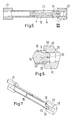
- Fig. 1 shows schematically a hydraulic machine in the form of a hydraulic pressure exchanger 1 in a longitudinal section.
- the pressure exchanger comprises a drum 2 rotatable about an axis 3.
- the term "drum” is used to facilitate the explanation. It is not necessary that this drum 2 is of cylindrical form.
- the main purpose of the drum 2 is to form a basis for cylinders 4.
- the drum 2 comprises a plurality of cylinders 4, two cylinders 4 being shown in Fig. 1 .
- the drum 2 can also be termed as "cylinder carrier".
- Each cylinder 4 is limited in circumferential direction by a wall 5.
- the term “cylinder” is used to simplify the description. It is not necessary that the cylinder has a circular cross section.
- a first front plate arrangement 6 is arranged at a first end face of the drum 2.
- a second front plate arrangement 7 is arranged at a second end face of the drum 2, said second end face being on the opposite side of the first end face of the drum 2.
- the first front plate arrangement 6 comprises a first front plate 8 and a pressure shoe 9.
- the first front plate 8 comprises a high pressure supply port 10 and a low pressure return port 11.
- the high pressure return port 10 is connected to a high pressure channel 12 of the pressure shoe 9 by means of a sleeve 13.
- the drum 2 is rotatable supported within a housing 14. Means for driving the drum 2 are not shown in order to keep the illustration simple. However, a driving shaft can be passed through the second front plate arrangement 7.
- Each cylinder 4 is provided with a piston 15.
- the piston 15 divides the cylinder 4 in a first chamber 16 and a second chamber 17.
- the piston 15 is moveable in a first direction from the first end face towards the second end face of the drum 2. Furthermore, the piston 15 is moveable in a second, opposite direction from the second end face towards the first end face of the drum 2.
- the movement of the piston 15 is caused by pressure differences.
- the upper piston is moved in the first direction under the influence of a hydraulic pressure present at the high pressure supply port 10.
- liquid present in the second chamber 17 is displaced to a high pressure return port 18 in the second front plate arrangement 7.
- the cylinder 4 comes in an overlap to a low pressure supply port 19.
- Fresh liquid under a pressure which is higher than the pressure at the low pressure return port 11 is supplied to the second chamber 17 moving the piston 15 in the second direction towards the first front plate arrangement 6 and pushing liquid out of the first chamber 16 into the low pressure return port 11.
- One way to increase the capacity of the hydraulic pressure exchanger 1 is to increase the rotational speed with which the drum 2 rotates.
- the pistons 15 have to be moved rather fast since they should be moved from the first end face to the second end face or vice versa during less than a half rotation of the drum 2.
- the high speed movement of the pistons 15 could cause trouble since the pistons 15 are suddenly stopped when they hit end stops (not shown). Such a stop causes noise which should be avoided.
- braking means are provided for both moving directions of the piston 15, such braking means are described in connection with Fig. 2 to 7 .
- Fig. 2 to 4 show the braking means for the first moving direction.
- the cylinder wall 5 is arranged between a holder 20 at the first end face of the drum 2 and a holder 21 at the second end face of the drum 2. It is possible to use the holder 20 as end stop.
- a sleeve 22 is arranged in the cylinder 4 surrounding the second chamber 17.
- the piston 15 comprises a section 23 which is guided in the sleeve 22.
- the inner diameter of sleeve 22 corresponds to the outer diameter of the section 23.
- the piston 15 has an area difference between the front faces so that the fluid in the exchanger can be amplified and can, in a reverse osmosis system, for example avoid a booster pump.
- the difference between the front faces of the piston can be realized in other ways and is not limited to the embodiment shown.
- the piston 15 comprises a further section 24 having a larger diameter.
- the diameter of the section 24 corresponds to the inner diameter of the cylinder 4.
- the piston 15 comprises a protrusion 25 being directed towards the first holder 20.
- a braking chamber 26 is limited by the cylinder wall 5, a circumferential face of the first section 23, a front face of the sleeve 22 and a front face of the second section 24 of the piston 15.
- This braking chamber 26 is connected via a first opening 27 with the interior of the housing 14. During a first part of the movement of the piston 15, this first opening 24 allows an almost unrestricted flow of fluid out of the braking chamber 26 into the interior of the housing 14 which is filled with liquid under low pressure, said low pressure corresponding to a pressure between the pressure at the low pressure supply port 19 and the pressure at the low pressure return port 11.
- the first opening 27, however, is open only during this first part of the movement of the piston 15 in the first direction. In other words, it is open only until the second section 24 of the piston 15 starts overlapping the first opening 27. During a further movement of the piston 15 in the first direction, the first opening 27 is gradually closed until the position shown in Fig. 2 to 4 is reached.
- the braking chamber 26 When the first opening 27 is closed, as shown in Fig. 2-4 , the braking chamber 26 is connected to the interior of the housing 14 by means of a first throttled outlet 28 only.
- the first throttled outlet 28 allows escape of liquid out of the braking chamber 26, however, the flow out of the braking chamber 26 is restricted. This restriction converts the kinetic energy of the piston 15 into heat.
- the first opening 27 can be made as a bore having a first diameter and the first throttled outlet 28 can be made by a bore having a second diameter, the second diameter being much smaller than the first diameter.
- the braking chamber 26 can be connected to the interior of the housing 14 by means of a check valve opening in a direction towards the braking chamber 26.
- a check valve facilitates refilling of the braking chamber 26 when the piston 15 is moved in the second direction.
- Fig. 3 shows a leakage path 29 between the sleeve 22 and the first section 23 of the piston 15. This leakage path 29 can be made just by a clearance between the sleeve 22 and the first section 23 of the piston 15. It can also be made by a groove running in longitudinal direction of the first section 23 of the piston 15.
- Fig. 5 to 7 show the braking means at the other end of the cylinder 4.
- the same elements are designated with the same reference numerals.
- a second braking chamber 30 is formed between the wall 5 of the cylinder, the protrusion 25 of the piston 15, a front face of the second section 24 and a front face of the holder 20.
- This second braking chamber 30 is open as long the protrusion 25 has not been inserted into a channel 31 in the holder 20 when the piston 15 moves in the second direction.
- the channel 31 is connected to the low pressure return port 11. In this way the second braking chamber 30 can unrestrictedly output the liquid in the first chamber 16 of the cylinder 4 into the low pressure return port 11 as long as the second braking chamber is not closed.
- the protrusion 25 comprises a tapered end 32.
- the tapered end 32 is shown to cover the complete circumference of the protrusion 25. However, in some cases it is sufficient that the tapered end extends only over part of the circumference.
- the channel 31 forms a second opening through which the liquid can escape out of the first chamber 16 when the piston moves in the second direction.
- the size of this opening is decreased when the protrusion 25 enters the channel 31.
- the size of the opening decreases gradually because of the tapered end 32.
- the second throttled outlet 33 comprises an orifice 34 by means of which the throttling effect of the second throttled outlet 33 can be adjusted.
Landscapes
- Engineering & Computer Science (AREA)
- Mechanical Engineering (AREA)
- General Engineering & Computer Science (AREA)
- Physics & Mathematics (AREA)
- Fluid Mechanics (AREA)
- Chemical & Material Sciences (AREA)
- Analytical Chemistry (AREA)
- Actuator (AREA)
- Hydraulic Motors (AREA)
- Reciprocating Pumps (AREA)
Priority Applications (2)
| Application Number | Priority Date | Filing Date | Title |
|---|---|---|---|
| EP14193210.3A EP3020968B1 (fr) | 2014-11-14 | 2014-11-14 | Machine hydraulique, en particulier un échangeur de pression hydraulique |
| CN201510784206.2A CN105605024A (zh) | 2014-11-14 | 2015-11-16 | 液压机器,尤其是液压交换器 |
Applications Claiming Priority (1)
| Application Number | Priority Date | Filing Date | Title |
|---|---|---|---|
| EP14193210.3A EP3020968B1 (fr) | 2014-11-14 | 2014-11-14 | Machine hydraulique, en particulier un échangeur de pression hydraulique |
Publications (2)
| Publication Number | Publication Date |
|---|---|
| EP3020968A1 true EP3020968A1 (fr) | 2016-05-18 |
| EP3020968B1 EP3020968B1 (fr) | 2016-08-24 |
Family
ID=51904768
Family Applications (1)
| Application Number | Title | Priority Date | Filing Date |
|---|---|---|---|
| EP14193210.3A Not-in-force EP3020968B1 (fr) | 2014-11-14 | 2014-11-14 | Machine hydraulique, en particulier un échangeur de pression hydraulique |
Country Status (2)
| Country | Link |
|---|---|
| EP (1) | EP3020968B1 (fr) |
| CN (1) | CN105605024A (fr) |
Cited By (3)
| Publication number | Priority date | Publication date | Assignee | Title |
|---|---|---|---|---|
| CN114810684A (zh) * | 2021-01-28 | 2022-07-29 | 丹佛斯有限公司 | 压力交换器 |
| US20230020630A1 (en) * | 2021-07-08 | 2023-01-19 | Energy Recovery, Inc. | Reduced mixing pressure exchanger |
| EP4130492A1 (fr) * | 2021-08-04 | 2023-02-08 | Danfoss A/S | Échangeur de pression |
Citations (3)
| Publication number | Priority date | Publication date | Assignee | Title |
|---|---|---|---|---|
| WO1991019094A1 (fr) * | 1990-06-05 | 1991-12-12 | Abb Mineral Slurry Transportation Pty. Ltd. | Ensemble d'orifices de soupape pour une pompe hydraulique refoulante a corps rotatif |
| EP1508361A1 (fr) | 2003-08-22 | 2005-02-23 | Danfoss A/S | Echangeur de pression |
| DE102011117081A1 (de) * | 2011-10-27 | 2013-05-02 | Robert Bosch Gmbh | Hydrostatische Kolbenmaschine |
Family Cites Families (3)
| Publication number | Priority date | Publication date | Assignee | Title |
|---|---|---|---|---|
| CN201099279Y (zh) * | 2007-08-28 | 2008-08-13 | 张保兴 | 一种控制备用助力泵的液压交换器 |
| US8065930B2 (en) * | 2008-03-26 | 2011-11-29 | GM Global Technology Operations LLC | Hydraulic actuator for transmissions having reduced noise |
| JP5360564B2 (ja) * | 2009-06-03 | 2013-12-04 | Smc株式会社 | 空気圧シリンダのエアクッション機構 |
-
2014
- 2014-11-14 EP EP14193210.3A patent/EP3020968B1/fr not_active Not-in-force
-
2015
- 2015-11-16 CN CN201510784206.2A patent/CN105605024A/zh active Pending
Patent Citations (3)
| Publication number | Priority date | Publication date | Assignee | Title |
|---|---|---|---|---|
| WO1991019094A1 (fr) * | 1990-06-05 | 1991-12-12 | Abb Mineral Slurry Transportation Pty. Ltd. | Ensemble d'orifices de soupape pour une pompe hydraulique refoulante a corps rotatif |
| EP1508361A1 (fr) | 2003-08-22 | 2005-02-23 | Danfoss A/S | Echangeur de pression |
| DE102011117081A1 (de) * | 2011-10-27 | 2013-05-02 | Robert Bosch Gmbh | Hydrostatische Kolbenmaschine |
Cited By (7)
| Publication number | Priority date | Publication date | Assignee | Title |
|---|---|---|---|---|
| CN114810684A (zh) * | 2021-01-28 | 2022-07-29 | 丹佛斯有限公司 | 压力交换器 |
| EP4036421A1 (fr) * | 2021-01-28 | 2022-08-03 | Danfoss Power Solutions ApS | Échangeur de pression |
| US11920573B2 (en) | 2021-01-28 | 2024-03-05 | Danfoss A/S | Pressure exchanger |
| CN114810684B (zh) * | 2021-01-28 | 2024-05-03 | 丹佛斯有限公司 | 压力交换器 |
| US20230020630A1 (en) * | 2021-07-08 | 2023-01-19 | Energy Recovery, Inc. | Reduced mixing pressure exchanger |
| EP4130492A1 (fr) * | 2021-08-04 | 2023-02-08 | Danfoss A/S | Échangeur de pression |
| US12270422B2 (en) | 2021-08-04 | 2025-04-08 | Danfoss A/S | Pressure exchanger |
Also Published As
| Publication number | Publication date |
|---|---|
| EP3020968B1 (fr) | 2016-08-24 |
| CN105605024A (zh) | 2016-05-25 |
Similar Documents
| Publication | Publication Date | Title |
|---|---|---|
| CN103195680B (zh) | 具有可变排量节流机构的液压活塞泵 | |
| US9067310B2 (en) | Sealing arrangement in rotating control valve of pressure fluid-operated percussion device | |
| EP3020968B1 (fr) | Machine hydraulique, en particulier un échangeur de pression hydraulique | |
| CA2298084A1 (fr) | Verin hydraulique a amortisseur | |
| NO170236B (no) | Lineaermotor | |
| KR101845596B1 (ko) | 스로틀 제어되는 유압식 피스톤 펌프 | |
| US10024158B2 (en) | Hydrostatic positive displacement machine | |
| RU2679516C1 (ru) | Гидравлический усилитель давления двойного действия | |
| US2780170A (en) | Supercharging system for fluid pumps | |
| US8776666B2 (en) | Hydraulic motor driving device | |
| KR101595193B1 (ko) | 전기 유압 하이브리드 구동 장치 | |
| JP2014077488A (ja) | シリンダ駆動装置 | |
| US10001114B1 (en) | Continuous flow pumping system | |
| US10233899B2 (en) | Hydrostatic axial piston machine | |
| CN107002716B (zh) | 用于调节阀、尤其蒸汽涡轮机调节阀的伺服驱动装置和其运行方法 | |
| ES2912172T3 (es) | Prensa para extrusión de material metálico | |
| US10240587B2 (en) | Hydrostatic axial piston machine | |
| US10107099B2 (en) | Hydrostatic radial piston machine | |
| US3415160A (en) | Multi-speed fluid translator | |
| AU2013354562A1 (en) | Hydraulic cylinder with end position damping | |
| CN113250922B (zh) | 带有压力侧更换的静液压的轴向活塞机 | |
| RU2362055C1 (ru) | Плоский гидрораспределитель | |
| RU2549754C1 (ru) | Система защиты гидропривода | |
| CN108571433B (zh) | 轴向柱塞机 | |
| CN107489612B (zh) | 电机动力装置 |
Legal Events
| Date | Code | Title | Description |
|---|---|---|---|
| PUAI | Public reference made under article 153(3) epc to a published international application that has entered the european phase |
Free format text: ORIGINAL CODE: 0009012 |
|
| 17P | Request for examination filed |
Effective date: 20150716 |
|
| AK | Designated contracting states |
Kind code of ref document: A1 Designated state(s): AL AT BE BG CH CY CZ DE DK EE ES FI FR GB GR HR HU IE IS IT LI LT LU LV MC MK MT NL NO PL PT RO RS SE SI SK SM TR |
|
| AX | Request for extension of the european patent |
Extension state: BA ME |
|
| GRAP | Despatch of communication of intention to grant a patent |
Free format text: ORIGINAL CODE: EPIDOSNIGR1 |
|
| INTG | Intention to grant announced |
Effective date: 20160607 |
|
| GRAS | Grant fee paid |
Free format text: ORIGINAL CODE: EPIDOSNIGR3 |
|
| GRAA | (expected) grant |
Free format text: ORIGINAL CODE: 0009210 |
|
| AK | Designated contracting states |
Kind code of ref document: B1 Designated state(s): AL AT BE BG CH CY CZ DE DK EE ES FI FR GB GR HR HU IE IS IT LI LT LU LV MC MK MT NL NO PL PT RO RS SE SI SK SM TR |
|
| REG | Reference to a national code |
Ref country code: GB Ref legal event code: FG4D |
|
| REG | Reference to a national code |
Ref country code: CH Ref legal event code: EP |
|
| REG | Reference to a national code |
Ref country code: AT Ref legal event code: REF Ref document number: 823358 Country of ref document: AT Kind code of ref document: T Effective date: 20160915 |
|
| REG | Reference to a national code |
Ref country code: IE Ref legal event code: FG4D |
|
| REG | Reference to a national code |
Ref country code: DE Ref legal event code: R096 Ref document number: 602014003253 Country of ref document: DE |
|
| REG | Reference to a national code |
Ref country code: LT Ref legal event code: MG4D |
|
| REG | Reference to a national code |
Ref country code: NL Ref legal event code: MP Effective date: 20160824 |
|
| REG | Reference to a national code |
Ref country code: AT Ref legal event code: MK05 Ref document number: 823358 Country of ref document: AT Kind code of ref document: T Effective date: 20160824 |
|
| PG25 | Lapsed in a contracting state [announced via postgrant information from national office to epo] |
Ref country code: NL Free format text: LAPSE BECAUSE OF FAILURE TO SUBMIT A TRANSLATION OF THE DESCRIPTION OR TO PAY THE FEE WITHIN THE PRESCRIBED TIME-LIMIT Effective date: 20160824 Ref country code: HR Free format text: LAPSE BECAUSE OF FAILURE TO SUBMIT A TRANSLATION OF THE DESCRIPTION OR TO PAY THE FEE WITHIN THE PRESCRIBED TIME-LIMIT Effective date: 20160824 Ref country code: LT Free format text: LAPSE BECAUSE OF FAILURE TO SUBMIT A TRANSLATION OF THE DESCRIPTION OR TO PAY THE FEE WITHIN THE PRESCRIBED TIME-LIMIT Effective date: 20160824 Ref country code: FI Free format text: LAPSE BECAUSE OF FAILURE TO SUBMIT A TRANSLATION OF THE DESCRIPTION OR TO PAY THE FEE WITHIN THE PRESCRIBED TIME-LIMIT Effective date: 20160824 Ref country code: RS Free format text: LAPSE BECAUSE OF FAILURE TO SUBMIT A TRANSLATION OF THE DESCRIPTION OR TO PAY THE FEE WITHIN THE PRESCRIBED TIME-LIMIT Effective date: 20160824 Ref country code: IT Free format text: LAPSE BECAUSE OF FAILURE TO SUBMIT A TRANSLATION OF THE DESCRIPTION OR TO PAY THE FEE WITHIN THE PRESCRIBED TIME-LIMIT Effective date: 20160824 Ref country code: NO Free format text: LAPSE BECAUSE OF FAILURE TO SUBMIT A TRANSLATION OF THE DESCRIPTION OR TO PAY THE FEE WITHIN THE PRESCRIBED TIME-LIMIT Effective date: 20161124 |
|
| PGFP | Annual fee paid to national office [announced via postgrant information from national office to epo] |
Ref country code: DE Payment date: 20161108 Year of fee payment: 3 |
|
| PG25 | Lapsed in a contracting state [announced via postgrant information from national office to epo] |
Ref country code: BE Free format text: LAPSE BECAUSE OF NON-PAYMENT OF DUE FEES Effective date: 20161130 Ref country code: AT Free format text: LAPSE BECAUSE OF FAILURE TO SUBMIT A TRANSLATION OF THE DESCRIPTION OR TO PAY THE FEE WITHIN THE PRESCRIBED TIME-LIMIT Effective date: 20160824 Ref country code: GR Free format text: LAPSE BECAUSE OF FAILURE TO SUBMIT A TRANSLATION OF THE DESCRIPTION OR TO PAY THE FEE WITHIN THE PRESCRIBED TIME-LIMIT Effective date: 20161125 Ref country code: ES Free format text: LAPSE BECAUSE OF FAILURE TO SUBMIT A TRANSLATION OF THE DESCRIPTION OR TO PAY THE FEE WITHIN THE PRESCRIBED TIME-LIMIT Effective date: 20160824 Ref country code: PT Free format text: LAPSE BECAUSE OF FAILURE TO SUBMIT A TRANSLATION OF THE DESCRIPTION OR TO PAY THE FEE WITHIN THE PRESCRIBED TIME-LIMIT Effective date: 20161226 Ref country code: SE Free format text: LAPSE BECAUSE OF FAILURE TO SUBMIT A TRANSLATION OF THE DESCRIPTION OR TO PAY THE FEE WITHIN THE PRESCRIBED TIME-LIMIT Effective date: 20160824 Ref country code: LV Free format text: LAPSE BECAUSE OF FAILURE TO SUBMIT A TRANSLATION OF THE DESCRIPTION OR TO PAY THE FEE WITHIN THE PRESCRIBED TIME-LIMIT Effective date: 20160824 |
|
| PG25 | Lapsed in a contracting state [announced via postgrant information from national office to epo] |
Ref country code: RO Free format text: LAPSE BECAUSE OF FAILURE TO SUBMIT A TRANSLATION OF THE DESCRIPTION OR TO PAY THE FEE WITHIN THE PRESCRIBED TIME-LIMIT Effective date: 20160824 Ref country code: EE Free format text: LAPSE BECAUSE OF FAILURE TO SUBMIT A TRANSLATION OF THE DESCRIPTION OR TO PAY THE FEE WITHIN THE PRESCRIBED TIME-LIMIT Effective date: 20160824 |
|
| REG | Reference to a national code |
Ref country code: DE Ref legal event code: R097 Ref document number: 602014003253 Country of ref document: DE |
|
| PG25 | Lapsed in a contracting state [announced via postgrant information from national office to epo] |
Ref country code: SK Free format text: LAPSE BECAUSE OF FAILURE TO SUBMIT A TRANSLATION OF THE DESCRIPTION OR TO PAY THE FEE WITHIN THE PRESCRIBED TIME-LIMIT Effective date: 20160824 Ref country code: CZ Free format text: LAPSE BECAUSE OF FAILURE TO SUBMIT A TRANSLATION OF THE DESCRIPTION OR TO PAY THE FEE WITHIN THE PRESCRIBED TIME-LIMIT Effective date: 20160824 Ref country code: BG Free format text: LAPSE BECAUSE OF FAILURE TO SUBMIT A TRANSLATION OF THE DESCRIPTION OR TO PAY THE FEE WITHIN THE PRESCRIBED TIME-LIMIT Effective date: 20161124 Ref country code: DK Free format text: LAPSE BECAUSE OF FAILURE TO SUBMIT A TRANSLATION OF THE DESCRIPTION OR TO PAY THE FEE WITHIN THE PRESCRIBED TIME-LIMIT Effective date: 20160824 Ref country code: PL Free format text: LAPSE BECAUSE OF FAILURE TO SUBMIT A TRANSLATION OF THE DESCRIPTION OR TO PAY THE FEE WITHIN THE PRESCRIBED TIME-LIMIT Effective date: 20160824 Ref country code: BE Free format text: LAPSE BECAUSE OF FAILURE TO SUBMIT A TRANSLATION OF THE DESCRIPTION OR TO PAY THE FEE WITHIN THE PRESCRIBED TIME-LIMIT Effective date: 20160824 Ref country code: SM Free format text: LAPSE BECAUSE OF FAILURE TO SUBMIT A TRANSLATION OF THE DESCRIPTION OR TO PAY THE FEE WITHIN THE PRESCRIBED TIME-LIMIT Effective date: 20160824 |
|
| PLBE | No opposition filed within time limit |
Free format text: ORIGINAL CODE: 0009261 |
|
| STAA | Information on the status of an ep patent application or granted ep patent |
Free format text: STATUS: NO OPPOSITION FILED WITHIN TIME LIMIT |
|
| 26N | No opposition filed |
Effective date: 20170526 |
|
| REG | Reference to a national code |
Ref country code: IE Ref legal event code: MM4A |
|
| REG | Reference to a national code |
Ref country code: FR Ref legal event code: ST Effective date: 20170731 |
|
| PG25 | Lapsed in a contracting state [announced via postgrant information from national office to epo] |
Ref country code: SI Free format text: LAPSE BECAUSE OF FAILURE TO SUBMIT A TRANSLATION OF THE DESCRIPTION OR TO PAY THE FEE WITHIN THE PRESCRIBED TIME-LIMIT Effective date: 20160824 |
|
| PG25 | Lapsed in a contracting state [announced via postgrant information from national office to epo] |
Ref country code: LU Free format text: LAPSE BECAUSE OF NON-PAYMENT OF DUE FEES Effective date: 20161130 |
|
| PG25 | Lapsed in a contracting state [announced via postgrant information from national office to epo] |
Ref country code: FR Free format text: LAPSE BECAUSE OF NON-PAYMENT OF DUE FEES Effective date: 20161130 |
|
| PG25 | Lapsed in a contracting state [announced via postgrant information from national office to epo] |
Ref country code: IE Free format text: LAPSE BECAUSE OF NON-PAYMENT OF DUE FEES Effective date: 20161114 |
|
| PG25 | Lapsed in a contracting state [announced via postgrant information from national office to epo] |
Ref country code: HU Free format text: LAPSE BECAUSE OF FAILURE TO SUBMIT A TRANSLATION OF THE DESCRIPTION OR TO PAY THE FEE WITHIN THE PRESCRIBED TIME-LIMIT; INVALID AB INITIO Effective date: 20141114 |
|
| REG | Reference to a national code |
Ref country code: DE Ref legal event code: R119 Ref document number: 602014003253 Country of ref document: DE |
|
| PG25 | Lapsed in a contracting state [announced via postgrant information from national office to epo] |
Ref country code: MC Free format text: LAPSE BECAUSE OF FAILURE TO SUBMIT A TRANSLATION OF THE DESCRIPTION OR TO PAY THE FEE WITHIN THE PRESCRIBED TIME-LIMIT Effective date: 20160824 Ref country code: IS Free format text: LAPSE BECAUSE OF FAILURE TO SUBMIT A TRANSLATION OF THE DESCRIPTION OR TO PAY THE FEE WITHIN THE PRESCRIBED TIME-LIMIT Effective date: 20160824 Ref country code: MK Free format text: LAPSE BECAUSE OF FAILURE TO SUBMIT A TRANSLATION OF THE DESCRIPTION OR TO PAY THE FEE WITHIN THE PRESCRIBED TIME-LIMIT Effective date: 20160824 Ref country code: CY Free format text: LAPSE BECAUSE OF FAILURE TO SUBMIT A TRANSLATION OF THE DESCRIPTION OR TO PAY THE FEE WITHIN THE PRESCRIBED TIME-LIMIT Effective date: 20160824 |
|
| PG25 | Lapsed in a contracting state [announced via postgrant information from national office to epo] |
Ref country code: LI Free format text: LAPSE BECAUSE OF NON-PAYMENT OF DUE FEES Effective date: 20171130 Ref country code: CH Free format text: LAPSE BECAUSE OF NON-PAYMENT OF DUE FEES Effective date: 20171130 |
|
| PG25 | Lapsed in a contracting state [announced via postgrant information from national office to epo] |
Ref country code: MT Free format text: LAPSE BECAUSE OF NON-PAYMENT OF DUE FEES Effective date: 20161114 |
|
| PG25 | Lapsed in a contracting state [announced via postgrant information from national office to epo] |
Ref country code: AL Free format text: LAPSE BECAUSE OF FAILURE TO SUBMIT A TRANSLATION OF THE DESCRIPTION OR TO PAY THE FEE WITHIN THE PRESCRIBED TIME-LIMIT Effective date: 20160824 Ref country code: TR Free format text: LAPSE BECAUSE OF FAILURE TO SUBMIT A TRANSLATION OF THE DESCRIPTION OR TO PAY THE FEE WITHIN THE PRESCRIBED TIME-LIMIT Effective date: 20160824 Ref country code: DE Free format text: LAPSE BECAUSE OF NON-PAYMENT OF DUE FEES Effective date: 20180602 |
|
| GBPC | Gb: european patent ceased through non-payment of renewal fee |
Effective date: 20181114 |
|
| PG25 | Lapsed in a contracting state [announced via postgrant information from national office to epo] |
Ref country code: GB Free format text: LAPSE BECAUSE OF NON-PAYMENT OF DUE FEES Effective date: 20181114 |