EP3020971A1 - Kältemittelverdichter - Google Patents
Kältemittelverdichter Download PDFInfo
- Publication number
- EP3020971A1 EP3020971A1 EP15188978.9A EP15188978A EP3020971A1 EP 3020971 A1 EP3020971 A1 EP 3020971A1 EP 15188978 A EP15188978 A EP 15188978A EP 3020971 A1 EP3020971 A1 EP 3020971A1
- Authority
- EP
- European Patent Office
- Prior art keywords
- valve body
- refrigerant compressor
- nutenring
- axially
- axial
- Prior art date
- Legal status (The legal status is an assumption and is not a legal conclusion. Google has not performed a legal analysis and makes no representation as to the accuracy of the status listed.)
- Granted
Links
Images

Classifications
-
- F—MECHANICAL ENGINEERING; LIGHTING; HEATING; WEAPONS; BLASTING
- F04—POSITIVE - DISPLACEMENT MACHINES FOR LIQUIDS; PUMPS FOR LIQUIDS OR ELASTIC FLUIDS
- F04B—POSITIVE-DISPLACEMENT MACHINES FOR LIQUIDS; PUMPS
- F04B27/00—Multi-cylinder pumps specially adapted for elastic fluids and characterised by number or arrangement of cylinders
- F04B27/08—Multi-cylinder pumps specially adapted for elastic fluids and characterised by number or arrangement of cylinders having cylinders coaxial with, or parallel or inclined to, main shaft axis
- F04B27/14—Control
-
- F—MECHANICAL ENGINEERING; LIGHTING; HEATING; WEAPONS; BLASTING
- F16—ENGINEERING ELEMENTS AND UNITS; GENERAL MEASURES FOR PRODUCING AND MAINTAINING EFFECTIVE FUNCTIONING OF MACHINES OR INSTALLATIONS; THERMAL INSULATION IN GENERAL
- F16B—DEVICES FOR FASTENING OR SECURING CONSTRUCTIONAL ELEMENTS OR MACHINE PARTS TOGETHER, e.g. NAILS, BOLTS, CIRCLIPS, CLAMPS, CLIPS OR WEDGES; JOINTS OR JOINTING
- F16B21/00—Means for preventing relative axial movement of a pin, spigot, shaft or the like and a member surrounding it; Stud-and-socket releasable fastenings
- F16B21/10—Means for preventing relative axial movement of a pin, spigot, shaft or the like and a member surrounding it; Stud-and-socket releasable fastenings by separate parts
- F16B21/16—Means for preventing relative axial movement of a pin, spigot, shaft or the like and a member surrounding it; Stud-and-socket releasable fastenings by separate parts with grooves or notches in the pin or shaft
- F16B21/18—Means for preventing relative axial movement of a pin, spigot, shaft or the like and a member surrounding it; Stud-and-socket releasable fastenings by separate parts with grooves or notches in the pin or shaft with circlips or like resilient retaining devices, i.e. resilient in the plane of the ring or the like; Details
- F16B21/183—Means for preventing relative axial movement of a pin, spigot, shaft or the like and a member surrounding it; Stud-and-socket releasable fastenings by separate parts with grooves or notches in the pin or shaft with circlips or like resilient retaining devices, i.e. resilient in the plane of the ring or the like; Details internal, i.e. with spreading action
Definitions
- the invention relates to a refrigerant compressor according to the preamble of claim 1 of the invention.
- Refrigerant compressors have been known for some time. They serve to compress gaseous refrigerant in the cycle of an air conditioning system, such as an air conditioning system of a motor vehicle.
- the refrigerant compressor operates, for example, according to the principle of an axial piston pump with a plurality of evenly distributed over a circumference arranged and guided in a cylinder piston.
- the pistons are moved axially by means of a rotationally driven inclined or swash plate (or else swash plate, swivel ring).
- flutter valves are provided for each cylinder, which release the path to the pressure or suction side in accordance with the piston movement (cf. DE 43 26 366 A1 ).
- a control valve for variably adjusting the piston stroke of the refrigerant compressor may be provided.
- the control valve is formed by a valve body axially inserted in a bore of the housing of the refrigerant compressor and axially fixed by means of, for example, a Nutenrings from the outside valve body (see website: http://www.denso-am.co.uk/media/74742/Ift_ac_compressor_web_uk. pdf).
- the control valve When the refrigeration system is switched off, the control valve has a system pressure (internal pressure or refrigerant pressure) of up to 90 bar relative to the outside environment. Depending on the application, there may be a need for a secure fixation of the control valve. From the DE 10 2004 001 378 A1 already a measure to secure a snap ring is known, which snap ring is arranged in an annular groove of a ring gear of a transmission and a recorded in the ring gear ring gear fixed in the axial direction.
- an integrally formed with the ring gear wedge-shaped locking element is arranged between the end faces of the snap ring, which corresponds with wedge-shaped end faces of the snap ring and fixes the snap ring in the circumferential direction.
- the DE 10 2005 055 360 A1 describes a check valve, in particular for use in a fuel injection system, with a valve member, with a valve seat, and with a valve spring, wherein the valve spring at one end against the valve member and the other end against a Abutment supports.
- the valve member is formed as a sleeve and guided axially displaceably in a bore.
- the abutment is fixed by means of an explosive or grooved ring with round cross-section in the axial direction.
- the abutment forms an axial projection on the side of the retaining ring which, due to the spring force of the valve spring, penetrates into the space surrounding the snap ring.
- the abutment with axial projection forms a stop surface in the manner of an annular obliquely extending frustoconical surface, whereby the snap ring is pressed radially into the snap ring receiving circumferential or annular groove and so secured.
- the axial fixation of the abutment is no longer 100% guaranteed.
- the snap ring due to the spring-loaded abutment and the oblique stop surface of the circumferential groove emerges with the result that the function of the fuel injection system is at least impaired.
- the object of the invention is to provide a refrigerant compressor with a caused by a Nutenrings axial securing, in this case an axial securing a valve body, which axial securing does not have the above-described disadvantages of the prior art.
- an axial lock for the control valve of the refrigerant compressor is created at applied system pressure (internal pressure range), which also prevents, for example, a failure of the Nutenringes, such as a fraction, an undefined release of the axial securing.
- the locking of the axial securing takes place accordingly just about the system pressure does not have a spring element, as in the prior art ( DE 10 2005 055 360 A1 ) favors.
- the at least one axial projection only allows the states to be opened and locked or locked. The effectiveness of the successful locking is independent of the system pressure if it is sufficient to position the valve body with its axial projection in the space surrounding the Nutenring.
- an accidental release of the Nutenringes is at applied system pressure (misuse) effectively prevented.
- two or more cam-like axial projections may be provided, which in turn form part-circular boundary surfaces.
- a single axial projection may be provided, which forms an annular or largely annular boundary surface.
- the Nutenring a rectangular or square cross-section with accordingly arranged perpendicular to each other outer surfaces.
- the positive connection realized between the Nutenring and the valve body with the at least one axial projection is particularly effective.
- the Nutenring has radially inwardly directed or bulging perforated ends for handling the Nutenrings by means of a suitable tool, such as a Nutenring pliers.
- the said ends are fixed by an axial projection in the circumferential direction or positively received by corresponding recesses of an axial projection and fixed in said recesses in the circumferential direction, whereby said positive engagement between the Nutenring and the valve body is further improved with the at least one axial projection , Any undesirable movement of the Nutenrings in the circumferential direction relative to the valve body is thereby effectively prevented.
- the refrigerant compressor in question is a refrigerant compressor of the swash plate type, swash plate type or swivel ring type with a control valve formed by a valve body for variably setting a piston stroke or for switching on and off the refrigerant compressor.
- Fig. 1 to 3 show only the invention essential to the area of the housing 1 of a refrigerant compressor of the exemplary swash plate type, with a control valve which is formed as a unit by a so-called valve body 2.
- the functional parts of the control valve are not shown in detail and described, since not essential to the invention.
- said control valve is used for the variable adjustment of the piston stroke or for switching on and off of said refrigerant compressor.
- the refrigerant compressor has an internal pressure region 3 and an ambient pressure region 4.
- the pressure in the internal pressure range 3 or the system pressure or refrigerant pressure can be up to 90 bar with the refrigeration system switched off.
- the valve body 2 is presently cylindrical and arranged axially displaceable in a the inner pressure with the ambient pressure range 3, 4 connecting bore 5 of the housing 1.
- the valve body 2 is axially introduced during assembly from the ambient pressure region 4 forth in said bore 5.
- the valve body 2 closes by mediation of at least one sealing element 6, such as a ring seal, in particular O-ring seal, tight against the inner circumferential surface of the bore 5.
- the bore 5 has inside pressure range side, a step 7, which limits the insertion depth of the valve body 2.
- a Nutenring 8 is provided, which in turn ambient pressure range side of the bore 5 is inserted into an annular groove 9 of the bore 5 / is and is also referred to as an inner circlip.
- the Nutenring 8 radially inwardly directed or reaching perforated ends 10a, 10b for handling the Nutenrings 8 by means of a suitable, not graphically illustrated, but known per se tool, such as a Nutenring pliers on.
- valve body 2 If a sufficiently high system pressure is applied, the valve body 2 is pressed axially against the notched ring 8 as a result of a resultant force "F" acting axially thereon with an annular contact surface 11.
- the contact surface 11 is orthogonal to the effective direction of the said force "F".
- valve body 2 may also have varying diameter in the course of its height. The same applies to the space or bore 5 in which the valve body 2 is inserted (not shown in the drawing). Likewise, during the said height or valve height, different pressures may be applied. Decisive for the function, however, is the axial force component "F" resulting from all refrigerant and ambient pressures with their respective effective surfaces and design-dependent additional forces (for example frictional forces, weight forces), which must act in the direction of the outer side (ambient pressure region 4).
- F axial force component
- the valve body 2 has two approximately radially oppositely arranged axial projections 12a, 12b (continuous lines), which radial projections 12a, 12b are preferably formed integrally with the valve body 2.
- the radial projections 12a, 12b penetrate positively due to the above-described axial displacement of the valve body 2 in the space surrounding the Nutenring 8 and thus each form a part-circular boundary surface 14 for the Nutenring 8 in the radial direction preferably in such a way that the Nutenring 8 to said boundary surfaces 14 hugs.
- the boundary surfaces 14 are oriented in the effective direction of the force "F". As a result, the Nutenring 8 is radially fixed. A relative movement of the Nutenrings 8 radially inward is effectively prevented.
- the contact surface 11 and the boundary surfaces 14 are accordingly perpendicular to each other.
- the Nutenring 8 has a rectangular cross-section with also arranged at right angles to each other outer surfaces.
- the positive locking realized between the Nutenring- 8 and the valve body 2 with the axial projections 12 a, 12 b is particularly effective.
- a square cross-section of the Nutenrings 8 may be provided (not shown in the drawing).
- said ends 10a, 10b are directed radially inward or bulge at least partially radially inward.
- Embodiment variant of the invention can according to a second and also in Fig. 1 by the clever arrangement of axial projections 12a ', 12b' and in the present case 12c '(dashed lines) the ends 10a, 10b are fixed in the circumferential direction by two axial projections 12a', 12b 'immediately adjacent to these radially inwardly directed ends 10a, 10b or are arranged to their protrusions.
- the said positive connection between the Nutenring 8 and the valve body 2 is further improved. Any undesirable movement of the Nutenrings 8 in the circumferential direction relative to the valve body 2 is thereby effectively prevented.
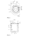
- the third embodiment of the invention according to 4 and 5 differs from the above-described in that only a single, substantially cylindrically shaped axial projection 15 is provided, which is arranged coaxially with the cylindrical valve body 2.
- Said axial projection 15 largely or predominantly forms an annular boundary surface 16 which is only interrupted by recesses 17, 18 corresponding to the perforated ends 10a, 10b of the Nutenring 8 in the peripheral surface of the axial projection 15.
- the recesses 17, 18 take the after radially inwardly directed or reaching perforated ends 10a, 10b in a form-fitting manner and fix them in the circumferential direction.
- the said positive connection between the Nutenring 8 and the valve body 2 is also further improved. Any undesirable movement of the Nutenrings 8 in the circumferential direction relative to the valve body 2 is thereby effectively prevented.
Landscapes
- Engineering & Computer Science (AREA)
- General Engineering & Computer Science (AREA)
- Mechanical Engineering (AREA)
- Compressors, Vaccum Pumps And Other Relevant Systems (AREA)
Abstract
Description
- Die Erfindung betrifft einen Kältemittelverdichter nach dem Oberbegriff des Patentanspruchs 1 der Erfindung.
- Kältemittelverdichter sind seit geraumer Zeit bekannt. Sie dienen dazu, gasförmiges Kältemittel im Kreislauf einer Klimaanlage, beispielsweise einer Klimaanlage eines Kraftfahrzeugs, zu verdichten. Der Kältemittelverdichter arbeitet beispielsweise nach dem Prinzip einer Axialkolbenpumpe mit einer Mehrzahl gleichmäßig über einen Umfang verteilt angeordneter und in je einem Zylinder geführter Kolben. Die Kolben werden mittels einer drehangetriebenen Schräg- oder Schwenkscheibe (oder auch Taumelscheibe, Schwenkring) axial bewegt. Im Zylinderkopf sind für jeden Zylinder Flatterventile vorgesehen, die entsprechend der Kolbenbewegung den Weg zur Druck- oder Saugseite freigeben (vgl. z. B.
DE 43 26 366 A1 ). - Überdies kann ein Regelventil zur variablen Einstellung des Kolbenhubs des Kältemittelverdichters vorgesehen sein. Das Regelventil ist durch einen in einer Bohrung des Gehäuses des Kältemittelverdichters axial eingesetzten und mittels beispielsweise eines Nutenrings von außen axial fixierten Ventilkörper gebildet (vgl. Internetseite: http://www.denso-am.co.uk/media/74742/Ift_ac_compressor_web_uk.pdf).
- Bei abgeschalteter Kälteanlage wirkt auf das Regelventil ein Systemdruck (Innendruck oder Kältemitteldruck) von bis zu 90 bar gegenüber der äußeren Umgebung. Abhängig vom Anwendungsfall kann Bedarf nach einer gesicherten Fixierung des Regelventils bestehen. Aus der
DE 10 2004 001 378 A1 ist bereits eine Maßnahme zur Sicherung eines Sprengrings bekannt, welcher Sprengring in einer Ringnut eines Hohlrades eines Getriebes angeordnet ist und einen im Hohlrad aufgenommenen Hohlradträger in axialer Richtung fixiert. Um ein schwingungsbedingtes selbsttätiges Lösen des Sprengrings aus der Ringnut zu verhindern, ist zwischen den Stirnflächen des Sprengrings ein einstückig mit dem Hohlradträger ausgebildetes keilförmiges Sperrelement angeordnet, welches mit keilförmigen Stirnflächen des Sprengrings korrespondiert und den Sprengring in Umfangsrichtung fixiert. DieDE 10 2005 055 360 A1 beschreibt ein Rückschlagventil, insbesondere zur Anwendung in einem Kraftstoffeinspritzsystem, mit einem Ventilglied, mit einem Ventilsitz, und mit einer Ventilfeder, wobei sich die Ventilfeder einenends gegen das Ventilglied und anderenends gegen ein Widerlager abstützt. Das Ventilglied ist als Hülse ausgebildet und in einer Bohrung axial verschiebbar geführt. Das Widerlager ist mittels eines Spreng- bzw. Nutenrings mit Rundquerschnitt in axialer Richtung fixiert. Das Widerlager bildet sprengringseitig einen Axialvorsprung aus, der infolge Federkraft der Ventilfeder in den vom Sprengring umgebenden Raum eindringt. Das Widerlager mit Axialvorsprung bildet dabei eine Anschlagfläche nach Art einer ringförmigen schräg verlaufenden Kegelstumpffläche aus, wodurch der Sprengring radial in die den Sprengring aufnehmende Umfangs- bzw. Ringnut gepresst und so gesichert werden soll. Bei einem etwaigen Versagen des Sprengrings, beispielsweise bei Bruch desselben ist jedoch die axiale Fixierung des Widerlagers nicht mehr 100%ig gewährleistet. Es besteht die Möglichkeit, dass unter ungünstigen Schwingungsbedingungen der Sprengring aufgrund des federkraftbeaufschlagten Widerlagers und der schrägen Anschlagfläche aus der Umfangsnut austritt mit der Folge, dass die Funktion des Kraftstoffeinspritzsystems zumindest beeinträchtigt ist. - Aufgabe der Erfindung ist es, einen Kältemittelverdichter mit einer mittels eines Nutenrings bewirkten Axialsicherung, vorliegend einer Axialsicherung eines Ventilkörpers zu schaffen, welche Axialsicherung die vorbeschriebenen Nachteile des Standes der Technik nicht aufweist.
- Ausgehend von einem Kältemittelverdichter, mit einem in Bezug auf die Umgebung überdruckbeaufschlagten Innendruckbereich sowie mit einem Regelventil, wobei das Regelventil durch einen in einer Bohrung eines Gehäuses des Kältemittelverdichters axial verschiebbaren und vom Innendruckbereich axial überdruckbeaufschlagten Ventilkörper gebildet ist, welcher Ventilkörper mittels eines Nutenringes innerhalb der Bohrung axial gesichert ist, indem der Ventilkörper mit einer ringförmigen Kontaktfläche axial am Nutenring anliegt, wird die gestellte Aufgabe dadurch gelöst, dass auf der umgebungsdruckbeaufschlagten Außenseite des Ventilkörpers zumindest ein Axialvorsprung vorgesehen oder ausgebildet ist, der infolge Innendruckbeaufschlagung des Ventilkörpers in den vom Nutenring umgebenden Raum formschlüssig eindringt und zumindest eine Begrenzungsfläche ausbildet, vermittels derer der Nutenring radial fixiert ist, wobei die Kontaktfläche orthogonal zur Wirkrichtung der auf den Ventilkörper wirkenden axialen Kraft "F" und die zumindest eine Begrenzungsfläche in Wirkrichtung der besagten Kraft "F" verlaufen.
- Durch diese Maßnahme ist bei anliegendem Systemdruck (Innendruckbereich) eine Axialsicherung für das Regelventil des Kältemittelverdichters geschaffen, welche auch bei beispielsweise einem Versagen des Nutenringes, wie einem Bruch desselben, ein undefiniertes Lösen der Axialsicherung verhindert. Die Verriegelung der Axialsicherung erfolgt demgemäß nur über den Systemdruck nicht über ein Federelement, wie es der Stand der Technik (
DE 10 2005 055 360 A1 ) favorisiert. Der zumindest eine Axialvorsprung erlaubt lediglich die Zustände geöffnet und gesperrt respektive verriegelt. Die Wirksamkeit der erfolgten Verriegelung ist unabhängig vom Systemdruck sofern dieser ausreicht, den Ventilkörper mit seinem Axialvorsprung im vom Nutenring umgebenden Raum zu positionieren. Darüber hinaus ist auch ein versehentliches Lösen des Nutenringes bei anliegendem Systemdruck (Missbrauchsfall) wirkungsvoll verhindert. - Die Unteransprüche beschreiben bevorzugte Weiterbildungen oder Ausgestaltungen der Erfindung.
- Danach können zwei oder mehr nockenartige Axialvorsprünge vorgesehen sein, die ihrerseits teilkreisartige Begrenzungsflächen ausbilden. Alternativ kann auch ein einziger Axialvorsprung vorgesehen sein, der eine ringförmige oder weitestgehend ringförmige Begrenzungsfläche ausbildet. Die erstbeschriebene Ausführung geht im Hinblick auf die zweitbeschriebene Ausführung mit Material- und Gewichtseinsparungen einher. Wie die Erfindung weiter vorsieht, weist der Nutenring einen rechteckigen oder quadratischen Querschnitt mit demgemäß rechtwinklig zueinander angeordneten Außenflächen auf. Hierdurch ist der zwischen dem Nutenring und dem Ventilkörper mit dem zumindest einen Axialvorsprung realisierte Formschluss besonders wirkungsvoll. Wie die Erfindung noch vorsieht, weist der Nutenring nach radial innen gerichtete oder vorwölbende gelochte Enden zur Handhabung des Nutenrings mittels eines geeigneten Werkzeugs, wie einer Nutenring-Zange auf. In Fortbildung der Erfindung sind die besagte Enden von je einem Axialvorsprung in Umfangsrichtung fixiert oder von korrespondierenden Ausnehmungen eines Axialvorsprungs formschlüssig aufgenommen und in besagten Ausnehmungen in Umfangsrichtung fixiert, wodurch der besagte Formschluss zwischen dem Nutenring und dem Ventilkörper mit dem zumindest einen Axialvorsprung noch weiter verbessert ist. Eine etwaige unerwünschte Bewegung des Nutenrings in Umfangsrichtung relativ zum Ventilkörper ist hierdurch wirkungsvoll verhindert. Bevorzugt handelt es sich bei dem in Rede stehenden Kältemittelverdichter um einen Kältemittelverdichter des Schwenkscheibentyps, Taumelscheibentyps oder Schwenkringtyps mit einem durch einen Ventilkörper gebildeten Regelventil zur variablen Einstellung eines Kolbenhubs oder zum Ein- und Ausschalten des Kältemittelverdichters.
- Nachstehend wird die Erfindung anhand der in den Zeichnungen schematisch dargestellten Ausführungsbeispiele näher erläutert. Sie ist jedoch nicht auf diese beschränkt, sondern erfasst alle durch die Patentansprüche definierten Ausgestaltungen. Es zeigen:
- Fig. 1
- eine Teilansicht (perspektivische Aufsicht) auf einen Kältemittelverdichter mit einem axial druckbeaufschlagten und mittels eines Nutenrings axial gesicherten Ventilkörper in zwei beispielgebenden Ausführungsvarianten,
- Fig. 2
- äußerst schematisch einen Teilschnitt "I-I" nach
Fig. 1 in einer Montagesituation des Ventilkörpers, - Fig. 3
- den Schnitt "I-I" nach
Fig. 1 in einer Endmontagesituation des Ventilkörpers, - Fig. 4
- eine Teilansicht (perspektivische Aufsicht) auf einen Kältemittelverdichter mit einem axial druckbeaufschlagten und mittels eines Nutenrings axial gesicherten Ventilkörper gemäß einer dritten Ausführungsvariante, und
- Fig. 5
- den Schnitt "II-II" nach
Fig. 1 in einer Endmontagesituation des Ventilkörpers. - Die
Fig. 1 bis 3 zeigen lediglich den erfindungswesentlichen Bereich des Gehäuses 1 eines Kältemittelverdichters des beispielsweisen Schwenkscheibentyps, mit einem Regelventil, welches als Baueinheit durch einen sogenannten Ventilkörper 2 gebildet ist. Die Funktionsteile des Regelventils sind im Detail nicht näher dargestellt und beschrieben, da nicht erfindungswesentlich. Wie eingangs bereits ausgeführt, dient besagtes Regelventil der variablen Einstellung des Kolbenhubs oder zum Ein- und Ausschalten des besagten Kältemittelverdichters. Der Kältemittelverdichter weist einen Innendruckbereich 3 und einen Umgebungsdruckbereich 4 auf. Der Druck im Innendruckbereich 3 respektive der Systemdruck oder Kältemitteldruck kann bis zu 90 bar betragen bei abgeschalteter Kälteanlage. - Der Ventilkörper 2 ist vorliegend zylindrisch ausgebildet und in eine den Innendruck- mit dem Umgebungsdruckbereich 3, 4 verbindende Bohrung 5 des Gehäuses 1 axial verschiebbar angeordnet. Der Ventilkörper 2 wird während der Montage vom Umgebungsdruckbereich 4 her in besagte Bohrung 5 axial eingeführt. Der Ventilkörper 2 schließt unter Vermittlung zumindest eines Dichtelements 6, wie einer Ringdichtung, insbesondere O-Ring-Dichtung, dicht an die Innenmantelfläche der Bohrung 5 an. Die Bohrung 5 weist innendruckbereichsseitig eine Stufe 7 auf, die die Einschubtiefe des Ventilkörpers 2 begrenzt.
- Nach dem Einsetzen des Ventilkörpers 2 in die Bohrung 5 wird der Ventilkörper 2 axial gesichert. Hierzu ist ein Nutenring 8 vorgesehen, der seinerseits umgebungsdruckbereichsseitig der Bohrung 5 in eine Ringnut 9 der Bohrung 5 eingesetzt wird/ist und auch als Innen-Sicherungsring bezeichnet wird. Hierzu weist der Nutenring 8 nach radial innen gerichtete oder reichende gelochte Enden 10a, 10b zur Handhabung des Nutenrings 8 mittels eines geeigneten, nicht zeichnerisch dargestellten, jedoch an sich bekannten Werkzeugs, wie einer Nutenring-Zange auf. Steht ein ausreichend hoher Systemdruck an, wird der Ventilkörper 2 infolge einer daraus resultierenden, axial auf denselben wirkenden Kraft "F" mit einer ringförmigen Kontaktfläche 11 axial gegen den Nutenring 8 gepresst. Die Kontaktfläche 11 verläuft orthogonal zur Wirkrichtung der besagten Kraft "F".
- Abweichend von der vereinfacht dargestellten zylindrischen Form des Ventilkörpers 2 mit einem durchgängigen Durchmesser kann der Ventilkörper 2 auch im Verlauf seiner Bauhöhe wechselnde Durchmesser aufweisen. Selbiges gilt für den Raum respektive die Bohrung 5, in welchem/r der Ventilkörper 2 eingesteckt ist (nicht zeichnerisch dargestellt). Ebenso können im Verlauf der besagten Bauhöhe bzw. Ventilhöhe unterschiedliche Drücke anliegen. Entscheidend für die Funktion ist jedoch die aus allen Kältemittel- und Umgebungsdrücken mit ihren jeweiligen Wirkflächen und ausführungsabhängigen weiteren Kräften (z.B. Reibkräfte, Gewichtskräfte) resultierende axiale Kraftkomponente "F", die in Richtung der Außenseite (Umgebungsdruckbereich 4) wirken muss.
- Der Ventilkörper 2 weist gemäß einer ersten bevorzugten Ausführungsvariante der Erfindung umgebungsdruckbereichsseitig zwei annähernd radial gegenüberliegend angeordnete Axialvorsprünge 12a, 12b auf (durchgehende Linienführung), welche Radialvorsprünge 12a, 12b bevorzugt einstückig mit dem Ventilkörper 2 ausgebildet sind. Die Radialvorsprünge 12a, 12b dringen infolge der vorbeschriebenen Axialverschiebung des Ventilkörpers 2 in den vom Nutenring 8 umgebenden Raum 13 formschlüssig ein und bilden so jeweils in radialer Richtung eine teilkreisartige Begrenzungsfläche 14 für den Nutenring 8 vorzugsweise derart aus, dass sich der Nutenring 8 an besagte Begrenzungsflächen 14 anschmiegt. Die Begrenzungsflächen 14 sind dabei in Wirkrichtung der Kraft "F" orientiert. Hierdurch ist der Nutenring 8 radial fixiert. Eine Relativbewegung des Nutenrings 8 nach radial innen ist wirkungsvoll verhindert.
- Die Kontaktfläche 11 und die Begrenzungsflächen 14 stehen demgemäß senkrecht aufeinander. Wie insbesondere den
Fig. 2 und 3 zu entnehmen ist, weist der Nutenring 8 einen rechteckigen Querschnitt mit ebenfalls rechtwinklig zueinander angeordnete Außenflächen auf. Hierdurch ist der zwischen dem Nutenring 8 und dem Ventilkörper 2 mit den Axialvorsprüngen 12a, 12b realisierte Formschluss besonders wirkungsvoll. Alternativ kann selbstverständlich auch ein quadratischer Querschnitt des Nutenrings 8 vorgesehen sein (nicht zeichnerisch dargestellt). - Wie bereits oben beschrieben, sind die besagten Enden 10a, 10b nach radial innen gerichtet oder wölben sich zumindest teilweise nach radial innen vor. Alternativ zur vorstehenden ersten
- Ausführungsvariante der Erfindung können gemäß einer zweiten und ebenfalls in
Fig. 1 gezeigten Ausführungsvariante durch geschickte Anordnung von Axialvorsprüngen 12a', 12b' und vorliegend weiter 12c' (gestrichelte Linienführung) die Enden 10a, 10b in Umfangsrichtung fixiert werden, indem zwei Axialvorsprünge 12a', 12b' unmittelbar benachbart zu besagten nach radial innen gerichteten Enden 10a, 10b bzw. zu deren Vorwölbungen angeordnet sind. Hierdurch ist der besagte Formschluss zwischen dem Nutenring 8 und dem Ventilkörper 2 noch weiter verbessert. Eine etwaige unerwünschte Bewegung des Nutenrings 8 in Umfangsrichtung relativ zum Ventilkörper 2 ist hierdurch wirkungsvoll verhindert. - Die dritte Ausführungsvariante der Erfindung nach
Fig. 4 und 5 unterscheidet sich zu den vorbeschriebenen dadurch, dass lediglich ein einziger, im Wesentlichen zylindrisch ausgebildeter Axialvorsprung 15 vorgesehen ist, der koaxial zum zylindrischen Ventilkörper 2 angeordnet ist. Der besagte Axialvorsprung 15 bildet weitestgehend bzw. überwiegend eine ringförmige Begrenzungsfläche 16 aus, die lediglich unterbrochen ist durch zu den gelochten Enden 10a, 10b des Nutenrings 8 korrespondierende Ausnehmungen 17, 18 in der Umfangsfläche des Axialvorsprungs 15. Die Ausnehmungen 17, 18 nehmen die nach radial innen gerichteten oder reichenden gelochten Enden 10a, 10b formschlüssig auf und fixieren diese in Umfangsrichtung. Hierdurch ist ebenfalls der besagte Formschluss zwischen dem Nutenring 8 und dem Ventilkörper 2 noch weiter verbessert. Eine etwaige unerwünschte Bewegung des Nutenrings 8 in Umfangsrichtung relativ zum Ventilkörper 2 ist hierdurch wirkungsvoll verhindert. -
- 1
- Gehäuse
- 2
- Ventilkörper
- 3
- Innendruckbereich
- 4
- Umgebungsdruckbereich
- 5
- Bohrung
- 6
- Dichtelement
- 7
- Stufe
- 8
- Nutenring
- 9
- Ringnut
- 10a
- Ende (Nutenring 8)
- 10b
- Ende (Nutenring 8)
- 11
- Kontaktfläche
- 12a
- Axialvorsprung
- 12b
- Axialvorsprung
- 12a'
- Axialvorsprung
- 12b'
- Axialvorsprung
- 12c'
- Axialvorsprung
- 13
- Raum
- 14
- Begrenzungsflächen
- 15
- Axialvorsprung
- 16
- Begrenzungsfläche
- 17
- Ausnehmung
- 18
- Ausnehmung
Claims (6)
- Kältemittelverdichter, mit einem in Bezug auf die Umgebung überdruckbeaufschlagten Innendruckbereich (3) sowie mit einem Regelventil, wobei das Regelventil durch einen in einer Bohrung (5) eines Gehäuses (1) des Kältemittelverdichters axial verschiebbaren und vom Innendruckbereich (3) axial überdruckbeaufschlagten Ventilkörper (2) gebildet ist, welcher Ventilkörper (2) mittels eines Nutenringes (8) innerhalb der Bohrung (5) axial gesichert ist, indem der Ventilkörper (2) mit einer ringförmigen Kontaktfläche (11) axial am Nutenring (8) anliegt, dadurch gekennzeichnet, dass auf der umgebungsdruckbeaufschlagten Außenseite des Ventilkörpers (2) zumindest ein Axialvorsprung (12a, 12b; 12a', 12b', 12c'; 15) vorgesehen oder ausgebildet ist, der infolge Innendruckbeaufschlagung des Ventilkörpers (2) in den vom Nutenring (8) umgebenden Raum (13) formschlüssig eindringt und zumindest eine Begrenzungsfläche (14; 16) ausbildet, vermittels derer der Nutenring (8) radial fixiert ist, wobei die Kontaktfläche (11) orthogonal zur Wirkrichtung der auf den Ventilkörper (2) wirkenden axialen Kraft "F" und die zumindest eine Begrenzungsfläche (14; 16) in Wirkrichtung der besagten Kraft "F" verlaufen.
- Kältemittelverdichter nach Anspruch 1, dadurch gekennzeichnet, dass zwei oder mehr nockenartige Axialvorsprünge (12a, 12b; 12a', 12b', 12c') vorgesehen sind, die ihrerseits teilkreisartige Begrenzungsflächen (14) ausbilden.
- Kältemittelverdichter nach Anspruch 1, dadurch gekennzeichnet, dass mittels eines einzigen Axialvorsprungs (15) eine ringförmige oder weitestgehend ringförmige Begrenzungsfläche (16) ausgebildet ist.
- Kältemittelverdichter nach einem der Ansprüche 1 bis 3, dadurch gekennzeichnet, dass der Nutenring (8) einen rechteckigen oder quadratischen Querschnitt aufweist.
- Kältemittelverdichter nach einem der Ansprüche 1 bis 4, dadurch gekennzeichnet, dass der Nutenring (8) zwei nach radial innen gerichtete oder vorwölbende gelochte Enden (10a, 10b) aufweist und besagte Enden (10a, 10b) von je einem Axialvorsprung (12a', 12b') in Umfangsrichtung fixiert oder von korrespondierenden Ausnehmungen (17, 18) des zumindest einen Axialvorsprungs (15) formschlüssig aufgenommen und in besagten Ausnehmungen (17, 18) in Umfangsrichtung fixiert sind.
- Kältemittelverdichter nach einem der Ansprüche 1 bis 5, dadurch gekennzeichnet, dass dieser ein Kältemittelverdichter des Schwenkscheibentyps, Taumelscheibentyps oder Schwenkringtyps mit einem durch einen Ventilkörper (2) gebildeten Regelventil zur variablen Einstellung eines Kolbenhubs oder zum Ein- und Ausschalten des Kältemittelverdichters ist.
Applications Claiming Priority (1)
| Application Number | Priority Date | Filing Date | Title |
|---|---|---|---|
| DE102014223262.7A DE102014223262A1 (de) | 2014-11-14 | 2014-11-14 | Kältemittelverdichter |
Publications (2)
| Publication Number | Publication Date |
|---|---|
| EP3020971A1 true EP3020971A1 (de) | 2016-05-18 |
| EP3020971B1 EP3020971B1 (de) | 2017-12-13 |
Family
ID=54291149
Family Applications (1)
| Application Number | Title | Priority Date | Filing Date |
|---|---|---|---|
| EP15188978.9A Active EP3020971B1 (de) | 2014-11-14 | 2015-10-08 | Kältemittelverdichter |
Country Status (2)
| Country | Link |
|---|---|
| EP (1) | EP3020971B1 (de) |
| DE (1) | DE102014223262A1 (de) |
Cited By (1)
| Publication number | Priority date | Publication date | Assignee | Title |
|---|---|---|---|---|
| EP4310371A1 (de) * | 2022-07-20 | 2024-01-24 | Oventrop GmbH & Co. KG | Armatur mit ventilelement |
Families Citing this family (1)
| Publication number | Priority date | Publication date | Assignee | Title |
|---|---|---|---|---|
| JP2018076800A (ja) | 2016-11-08 | 2018-05-17 | サンデン・オートモーティブコンポーネント株式会社 | 冷媒圧縮機の電磁制御弁取付構造 |
Citations (6)
| Publication number | Priority date | Publication date | Assignee | Title |
|---|---|---|---|---|
| DE4326366A1 (de) | 1992-08-07 | 1994-02-24 | Toyoda Automatic Loom Works | Kompressor der Taumelscheibenbauart |
| DE102004001378A1 (de) | 2004-01-09 | 2005-08-04 | Zf Friedrichshafen Ag | Sprengringsicherung |
| JP2006242003A (ja) * | 2005-02-28 | 2006-09-14 | Sanden Corp | 圧縮機の電磁制御弁取付け部構造 |
| DE102005055360A1 (de) | 2005-11-21 | 2007-05-24 | Robert Bosch Gmbh | Rückschlagventil und Injektor mit hydraulischem Übersetzer |
| DE102008052279A1 (de) * | 2008-10-18 | 2010-04-22 | Schaeffler Kg | Schaltbares Bauteil für einen Ventiltrieb einer Brennkraftmaschine |
| EP2573394A1 (de) * | 2010-05-15 | 2013-03-27 | Kabushiki Kaisha Toyota Jidoshokki | Kompressor von variabler kapazität |
-
2014
- 2014-11-14 DE DE102014223262.7A patent/DE102014223262A1/de not_active Withdrawn
-
2015
- 2015-10-08 EP EP15188978.9A patent/EP3020971B1/de active Active
Patent Citations (6)
| Publication number | Priority date | Publication date | Assignee | Title |
|---|---|---|---|---|
| DE4326366A1 (de) | 1992-08-07 | 1994-02-24 | Toyoda Automatic Loom Works | Kompressor der Taumelscheibenbauart |
| DE102004001378A1 (de) | 2004-01-09 | 2005-08-04 | Zf Friedrichshafen Ag | Sprengringsicherung |
| JP2006242003A (ja) * | 2005-02-28 | 2006-09-14 | Sanden Corp | 圧縮機の電磁制御弁取付け部構造 |
| DE102005055360A1 (de) | 2005-11-21 | 2007-05-24 | Robert Bosch Gmbh | Rückschlagventil und Injektor mit hydraulischem Übersetzer |
| DE102008052279A1 (de) * | 2008-10-18 | 2010-04-22 | Schaeffler Kg | Schaltbares Bauteil für einen Ventiltrieb einer Brennkraftmaschine |
| EP2573394A1 (de) * | 2010-05-15 | 2013-03-27 | Kabushiki Kaisha Toyota Jidoshokki | Kompressor von variabler kapazität |
Cited By (1)
| Publication number | Priority date | Publication date | Assignee | Title |
|---|---|---|---|---|
| EP4310371A1 (de) * | 2022-07-20 | 2024-01-24 | Oventrop GmbH & Co. KG | Armatur mit ventilelement |
Also Published As
| Publication number | Publication date |
|---|---|
| DE102014223262A1 (de) | 2016-05-19 |
| EP3020971B1 (de) | 2017-12-13 |
Similar Documents
| Publication | Publication Date | Title |
|---|---|---|
| EP2821619B1 (de) | Pleuel für eine zweistufige variable Verdichtung | |
| DE102015111175A1 (de) | Hydraulikventil und Pleuel mit einem Hydraulikventil | |
| WO2015110104A1 (de) | Ventileinheit mit einem überdruck- und einem rückschlagventil | |
| DE102015109924A1 (de) | Kolben für eine Pleuelstange und Pleuelstange | |
| EP2855943B1 (de) | Geberzylinder | |
| DE102012022694A1 (de) | Regelventil, insbesondere für eine elektroproportionale Schwenkwinkelregelung einer Hydromaschine | |
| WO2014131495A2 (de) | Überströmventil | |
| EP3020971B1 (de) | Kältemittelverdichter | |
| DE102008010238A1 (de) | Hochdruckelement für Einspritzanlagen von Brennkraftmaschinen | |
| EP2264329A1 (de) | Druckmittelzylinder für eine Betätigungseinrichtung eines Kraftfahrzeuges mit einem arretierbaren Kolben | |
| DE102005046065A1 (de) | Stromventil zum Drosseln hydraulischer Druckmittel | |
| DE102017113250A1 (de) | Kolben für eine Pleuelstange und Pleuelstange | |
| EP3073095B1 (de) | Hydraulikventil und pleuel mit einem hydraulikventil | |
| DE102015111273A1 (de) | Hydraulikventil und Pleuel mit einem Hydraulikventil | |
| EP3514418B1 (de) | Einbauventil für einen ventilblock | |
| DE102019119854A1 (de) | Pleuel für eine Brennkraftmaschine mit variabler Verdichtung | |
| DE102014214293A1 (de) | Kraftstoffhochdruckpumpe, insbesondere Steckpumpe | |
| DE102018107057A1 (de) | Pleuel für eine Brennkraftmaschine mit variabler Verdichtung | |
| DE102008024157A1 (de) | Druckmittelzylinder mit Mitteln zur Erzeugung eines Mindestauslösedrucks | |
| DE102009026567A1 (de) | Kraftstoffinjektor mit Druckverstärkerkolben | |
| DE102018203769A1 (de) | Kraftstofffördereinrichtung für kryogene Kraftstoffe | |
| WO2017157649A1 (de) | Kugelgelenk und pleuel mit einem kugelgelenk | |
| EP3267012A1 (de) | Rückschlagventil für einen pleuel für eine brennkraftmaschine mit variabler verdichtung | |
| EP2212554B1 (de) | Radialkolbenpumpe | |
| DE102015223166A1 (de) | Elektromagnetisch ansteuerbares Saugventil für eine Hochdruckpumpe, Hochdruckpumpe |
Legal Events
| Date | Code | Title | Description |
|---|---|---|---|
| PUAI | Public reference made under article 153(3) epc to a published international application that has entered the european phase |
Free format text: ORIGINAL CODE: 0009012 |
|
| AK | Designated contracting states |
Kind code of ref document: A1 Designated state(s): AL AT BE BG CH CY CZ DE DK EE ES FI FR GB GR HR HU IE IS IT LI LT LU LV MC MK MT NL NO PL PT RO RS SE SI SK SM TR |
|
| AX | Request for extension of the european patent |
Extension state: BA ME |
|
| 17P | Request for examination filed |
Effective date: 20161118 |
|
| RBV | Designated contracting states (corrected) |
Designated state(s): AL AT BE BG CH CY CZ DE DK EE ES FI FR GB GR HR HU IE IS IT LI LT LU LV MC MK MT NL NO PL PT RO RS SE SI SK SM TR |
|
| GRAP | Despatch of communication of intention to grant a patent |
Free format text: ORIGINAL CODE: EPIDOSNIGR1 |
|
| INTG | Intention to grant announced |
Effective date: 20170526 |
|
| GRAS | Grant fee paid |
Free format text: ORIGINAL CODE: EPIDOSNIGR3 |
|
| GRAA | (expected) grant |
Free format text: ORIGINAL CODE: 0009210 |
|
| REG | Reference to a national code |
Ref country code: GB Ref legal event code: FG4D Free format text: NOT ENGLISH |
|
| REG | Reference to a national code |
Ref country code: AT Ref legal event code: REF Ref document number: 954659 Country of ref document: AT Kind code of ref document: T Effective date: 20171215 Ref country code: CH Ref legal event code: EP |
|
| REG | Reference to a national code |
Ref country code: IE Ref legal event code: FG4D Free format text: LANGUAGE OF EP DOCUMENT: GERMAN |
|
| REG | Reference to a national code |
Ref country code: DE Ref legal event code: R096 Ref document number: 502015002554 Country of ref document: DE |
|
| REG | Reference to a national code |
Ref country code: NL Ref legal event code: MP Effective date: 20171213 |
|
| PG25 | Lapsed in a contracting state [announced via postgrant information from national office to epo] |
Ref country code: NO Free format text: LAPSE BECAUSE OF FAILURE TO SUBMIT A TRANSLATION OF THE DESCRIPTION OR TO PAY THE FEE WITHIN THE PRESCRIBED TIME-LIMIT Effective date: 20180313 Ref country code: SE Free format text: LAPSE BECAUSE OF FAILURE TO SUBMIT A TRANSLATION OF THE DESCRIPTION OR TO PAY THE FEE WITHIN THE PRESCRIBED TIME-LIMIT Effective date: 20171213 Ref country code: FI Free format text: LAPSE BECAUSE OF FAILURE TO SUBMIT A TRANSLATION OF THE DESCRIPTION OR TO PAY THE FEE WITHIN THE PRESCRIBED TIME-LIMIT Effective date: 20171213 |
|
| PG25 | Lapsed in a contracting state [announced via postgrant information from national office to epo] |
Ref country code: RS Free format text: LAPSE BECAUSE OF FAILURE TO SUBMIT A TRANSLATION OF THE DESCRIPTION OR TO PAY THE FEE WITHIN THE PRESCRIBED TIME-LIMIT Effective date: 20171213 Ref country code: HR Free format text: LAPSE BECAUSE OF FAILURE TO SUBMIT A TRANSLATION OF THE DESCRIPTION OR TO PAY THE FEE WITHIN THE PRESCRIBED TIME-LIMIT Effective date: 20171213 Ref country code: BG Free format text: LAPSE BECAUSE OF FAILURE TO SUBMIT A TRANSLATION OF THE DESCRIPTION OR TO PAY THE FEE WITHIN THE PRESCRIBED TIME-LIMIT Effective date: 20180313 Ref country code: LV Free format text: LAPSE BECAUSE OF FAILURE TO SUBMIT A TRANSLATION OF THE DESCRIPTION OR TO PAY THE FEE WITHIN THE PRESCRIBED TIME-LIMIT Effective date: 20171213 Ref country code: GR Free format text: LAPSE BECAUSE OF FAILURE TO SUBMIT A TRANSLATION OF THE DESCRIPTION OR TO PAY THE FEE WITHIN THE PRESCRIBED TIME-LIMIT Effective date: 20180314 |
|
| PG25 | Lapsed in a contracting state [announced via postgrant information from national office to epo] |
Ref country code: NL Free format text: LAPSE BECAUSE OF FAILURE TO SUBMIT A TRANSLATION OF THE DESCRIPTION OR TO PAY THE FEE WITHIN THE PRESCRIBED TIME-LIMIT Effective date: 20171213 |
|
| PG25 | Lapsed in a contracting state [announced via postgrant information from national office to epo] |
Ref country code: CZ Free format text: LAPSE BECAUSE OF FAILURE TO SUBMIT A TRANSLATION OF THE DESCRIPTION OR TO PAY THE FEE WITHIN THE PRESCRIBED TIME-LIMIT Effective date: 20171213 Ref country code: ES Free format text: LAPSE BECAUSE OF FAILURE TO SUBMIT A TRANSLATION OF THE DESCRIPTION OR TO PAY THE FEE WITHIN THE PRESCRIBED TIME-LIMIT Effective date: 20171213 Ref country code: EE Free format text: LAPSE BECAUSE OF FAILURE TO SUBMIT A TRANSLATION OF THE DESCRIPTION OR TO PAY THE FEE WITHIN THE PRESCRIBED TIME-LIMIT Effective date: 20171213 Ref country code: CY Free format text: LAPSE BECAUSE OF FAILURE TO SUBMIT A TRANSLATION OF THE DESCRIPTION OR TO PAY THE FEE WITHIN THE PRESCRIBED TIME-LIMIT Effective date: 20171213 Ref country code: SK Free format text: LAPSE BECAUSE OF FAILURE TO SUBMIT A TRANSLATION OF THE DESCRIPTION OR TO PAY THE FEE WITHIN THE PRESCRIBED TIME-LIMIT Effective date: 20171213 |
|
| PG25 | Lapsed in a contracting state [announced via postgrant information from national office to epo] |
Ref country code: RO Free format text: LAPSE BECAUSE OF FAILURE TO SUBMIT A TRANSLATION OF THE DESCRIPTION OR TO PAY THE FEE WITHIN THE PRESCRIBED TIME-LIMIT Effective date: 20171213 Ref country code: IS Free format text: LAPSE BECAUSE OF FAILURE TO SUBMIT A TRANSLATION OF THE DESCRIPTION OR TO PAY THE FEE WITHIN THE PRESCRIBED TIME-LIMIT Effective date: 20180413 Ref country code: PL Free format text: LAPSE BECAUSE OF FAILURE TO SUBMIT A TRANSLATION OF THE DESCRIPTION OR TO PAY THE FEE WITHIN THE PRESCRIBED TIME-LIMIT Effective date: 20171213 Ref country code: SM Free format text: LAPSE BECAUSE OF FAILURE TO SUBMIT A TRANSLATION OF THE DESCRIPTION OR TO PAY THE FEE WITHIN THE PRESCRIBED TIME-LIMIT Effective date: 20171213 Ref country code: IT Free format text: LAPSE BECAUSE OF FAILURE TO SUBMIT A TRANSLATION OF THE DESCRIPTION OR TO PAY THE FEE WITHIN THE PRESCRIBED TIME-LIMIT Effective date: 20171213 |
|
| REG | Reference to a national code |
Ref country code: DE Ref legal event code: R097 Ref document number: 502015002554 Country of ref document: DE |
|
| PG25 | Lapsed in a contracting state [announced via postgrant information from national office to epo] |
Ref country code: MT Free format text: LAPSE BECAUSE OF FAILURE TO SUBMIT A TRANSLATION OF THE DESCRIPTION OR TO PAY THE FEE WITHIN THE PRESCRIBED TIME-LIMIT Effective date: 20171213 |
|
| PLBE | No opposition filed within time limit |
Free format text: ORIGINAL CODE: 0009261 |
|
| STAA | Information on the status of an ep patent application or granted ep patent |
Free format text: STATUS: NO OPPOSITION FILED WITHIN TIME LIMIT |
|
| REG | Reference to a national code |
Ref country code: FR Ref legal event code: PLFP Year of fee payment: 4 |
|
| 26N | No opposition filed |
Effective date: 20180914 |
|
| PG25 | Lapsed in a contracting state [announced via postgrant information from national office to epo] |
Ref country code: DK Free format text: LAPSE BECAUSE OF FAILURE TO SUBMIT A TRANSLATION OF THE DESCRIPTION OR TO PAY THE FEE WITHIN THE PRESCRIBED TIME-LIMIT Effective date: 20171213 |
|
| PG25 | Lapsed in a contracting state [announced via postgrant information from national office to epo] |
Ref country code: SI Free format text: LAPSE BECAUSE OF FAILURE TO SUBMIT A TRANSLATION OF THE DESCRIPTION OR TO PAY THE FEE WITHIN THE PRESCRIBED TIME-LIMIT Effective date: 20171213 |
|
| REG | Reference to a national code |
Ref country code: CH Ref legal event code: PL |
|
| REG | Reference to a national code |
Ref country code: BE Ref legal event code: MM Effective date: 20181031 |
|
| PG25 | Lapsed in a contracting state [announced via postgrant information from national office to epo] |
Ref country code: MC Free format text: LAPSE BECAUSE OF FAILURE TO SUBMIT A TRANSLATION OF THE DESCRIPTION OR TO PAY THE FEE WITHIN THE PRESCRIBED TIME-LIMIT Effective date: 20171213 Ref country code: LU Free format text: LAPSE BECAUSE OF NON-PAYMENT OF DUE FEES Effective date: 20181008 |
|
| REG | Reference to a national code |
Ref country code: IE Ref legal event code: MM4A |
|
| PG25 | Lapsed in a contracting state [announced via postgrant information from national office to epo] |
Ref country code: BE Free format text: LAPSE BECAUSE OF NON-PAYMENT OF DUE FEES Effective date: 20181031 Ref country code: LI Free format text: LAPSE BECAUSE OF NON-PAYMENT OF DUE FEES Effective date: 20181031 Ref country code: CH Free format text: LAPSE BECAUSE OF NON-PAYMENT OF DUE FEES Effective date: 20181031 |
|
| PG25 | Lapsed in a contracting state [announced via postgrant information from national office to epo] |
Ref country code: IE Free format text: LAPSE BECAUSE OF NON-PAYMENT OF DUE FEES Effective date: 20181008 |
|
| PG25 | Lapsed in a contracting state [announced via postgrant information from national office to epo] |
Ref country code: TR Free format text: LAPSE BECAUSE OF FAILURE TO SUBMIT A TRANSLATION OF THE DESCRIPTION OR TO PAY THE FEE WITHIN THE PRESCRIBED TIME-LIMIT Effective date: 20171213 |
|
| PG25 | Lapsed in a contracting state [announced via postgrant information from national office to epo] |
Ref country code: PT Free format text: LAPSE BECAUSE OF FAILURE TO SUBMIT A TRANSLATION OF THE DESCRIPTION OR TO PAY THE FEE WITHIN THE PRESCRIBED TIME-LIMIT Effective date: 20171213 |
|
| PG25 | Lapsed in a contracting state [announced via postgrant information from national office to epo] |
Ref country code: MK Free format text: LAPSE BECAUSE OF NON-PAYMENT OF DUE FEES Effective date: 20171213 Ref country code: HU Free format text: LAPSE BECAUSE OF FAILURE TO SUBMIT A TRANSLATION OF THE DESCRIPTION OR TO PAY THE FEE WITHIN THE PRESCRIBED TIME-LIMIT; INVALID AB INITIO Effective date: 20151008 Ref country code: LT Free format text: LAPSE BECAUSE OF FAILURE TO SUBMIT A TRANSLATION OF THE DESCRIPTION OR TO PAY THE FEE WITHIN THE PRESCRIBED TIME-LIMIT Effective date: 20171213 |
|
| PG25 | Lapsed in a contracting state [announced via postgrant information from national office to epo] |
Ref country code: AL Free format text: LAPSE BECAUSE OF FAILURE TO SUBMIT A TRANSLATION OF THE DESCRIPTION OR TO PAY THE FEE WITHIN THE PRESCRIBED TIME-LIMIT Effective date: 20171213 |
|
| GBPC | Gb: european patent ceased through non-payment of renewal fee |
Effective date: 20191008 |
|
| PG25 | Lapsed in a contracting state [announced via postgrant information from national office to epo] |
Ref country code: GB Free format text: LAPSE BECAUSE OF NON-PAYMENT OF DUE FEES Effective date: 20191008 |
|
| REG | Reference to a national code |
Ref country code: AT Ref legal event code: MM01 Ref document number: 954659 Country of ref document: AT Kind code of ref document: T Effective date: 20201008 |
|
| PG25 | Lapsed in a contracting state [announced via postgrant information from national office to epo] |
Ref country code: AT Free format text: LAPSE BECAUSE OF NON-PAYMENT OF DUE FEES Effective date: 20201008 |
|
| P01 | Opt-out of the competence of the unified patent court (upc) registered |
Effective date: 20230523 |
|
| PGFP | Annual fee paid to national office [announced via postgrant information from national office to epo] |
Ref country code: DE Payment date: 20241031 Year of fee payment: 10 |
|
| PGFP | Annual fee paid to national office [announced via postgrant information from national office to epo] |
Ref country code: FR Payment date: 20241025 Year of fee payment: 10 |