EP3021008A1 - Procédé d'adaptation d'une transmission - Google Patents
Procédé d'adaptation d'une transmission Download PDFInfo
- Publication number
- EP3021008A1 EP3021008A1 EP15201385.0A EP15201385A EP3021008A1 EP 3021008 A1 EP3021008 A1 EP 3021008A1 EP 15201385 A EP15201385 A EP 15201385A EP 3021008 A1 EP3021008 A1 EP 3021008A1
- Authority
- EP
- European Patent Office
- Prior art keywords
- control module
- transmission control
- memory device
- vehicle
- transmission
- Prior art date
- Legal status (The legal status is an assumption and is not a legal conclusion. Google has not performed a legal analysis and makes no representation as to the accuracy of the status listed.)
- Withdrawn
Links
Images




Classifications
-
- F—MECHANICAL ENGINEERING; LIGHTING; HEATING; WEAPONS; BLASTING
- F16—ENGINEERING ELEMENTS AND UNITS; GENERAL MEASURES FOR PRODUCING AND MAINTAINING EFFECTIVE FUNCTIONING OF MACHINES OR INSTALLATIONS; THERMAL INSULATION IN GENERAL
- F16H—GEARING
- F16H59/00—Control inputs to control units of change-speed- or reversing-gearings for conveying rotary motion
-
- B—PERFORMING OPERATIONS; TRANSPORTING
- B60—VEHICLES IN GENERAL
- B60W—CONJOINT CONTROL OF VEHICLE SUB-UNITS OF DIFFERENT TYPE OR DIFFERENT FUNCTION; CONTROL SYSTEMS SPECIALLY ADAPTED FOR HYBRID VEHICLES; ROAD VEHICLE DRIVE CONTROL SYSTEMS FOR PURPOSES NOT RELATED TO THE CONTROL OF A PARTICULAR SUB-UNIT
- B60W50/00—Details of control systems for road vehicle drive control not related to the control of a particular sub-unit, e.g. process diagnostic or vehicle driver interfaces
- B60W50/0098—Details of control systems ensuring comfort, safety or stability not otherwise provided for
-
- F—MECHANICAL ENGINEERING; LIGHTING; HEATING; WEAPONS; BLASTING
- F16—ENGINEERING ELEMENTS AND UNITS; GENERAL MEASURES FOR PRODUCING AND MAINTAINING EFFECTIVE FUNCTIONING OF MACHINES OR INSTALLATIONS; THERMAL INSULATION IN GENERAL
- F16H—GEARING
- F16H61/00—Control functions within control units of change-speed- or reversing-gearings for conveying rotary motion ; Control of exclusively fluid gearing, friction gearing, gearings with endless flexible members or other particular types of gearing
- F16H61/02—Control functions within control units of change-speed- or reversing-gearings for conveying rotary motion ; Control of exclusively fluid gearing, friction gearing, gearings with endless flexible members or other particular types of gearing characterised by the signals used
- F16H61/0202—Control functions within control units of change-speed- or reversing-gearings for conveying rotary motion ; Control of exclusively fluid gearing, friction gearing, gearings with endless flexible members or other particular types of gearing characterised by the signals used the signals being electric
- F16H61/0204—Control functions within control units of change-speed- or reversing-gearings for conveying rotary motion ; Control of exclusively fluid gearing, friction gearing, gearings with endless flexible members or other particular types of gearing characterised by the signals used the signals being electric for gearshift control, e.g. control functions for performing shifting or generation of shift signal
-
- B—PERFORMING OPERATIONS; TRANSPORTING
- B60—VEHICLES IN GENERAL
- B60K—ARRANGEMENT OR MOUNTING OF PROPULSION UNITS OR OF TRANSMISSIONS IN VEHICLES; ARRANGEMENT OR MOUNTING OF PLURAL DIVERSE PRIME-MOVERS IN VEHICLES; AUXILIARY DRIVES FOR VEHICLES; INSTRUMENTATION OR DASHBOARDS FOR VEHICLES; ARRANGEMENTS IN CONNECTION WITH COOLING, AIR INTAKE, GAS EXHAUST OR FUEL SUPPLY OF PROPULSION UNITS IN VEHICLES
- B60K6/00—Arrangement or mounting of plural diverse prime-movers for mutual or common propulsion, e.g. hybrid propulsion systems comprising electric motors and internal combustion engines
- B60K6/20—Arrangement or mounting of plural diverse prime-movers for mutual or common propulsion, e.g. hybrid propulsion systems comprising electric motors and internal combustion engines the prime-movers consisting of electric motors and internal combustion engines, e.g. HEVs
- B60K6/42—Arrangement or mounting of plural diverse prime-movers for mutual or common propulsion, e.g. hybrid propulsion systems comprising electric motors and internal combustion engines the prime-movers consisting of electric motors and internal combustion engines, e.g. HEVs characterised by the architecture of the hybrid electric vehicle
- B60K6/48—Parallel type
-
- B—PERFORMING OPERATIONS; TRANSPORTING
- B60—VEHICLES IN GENERAL
- B60K—ARRANGEMENT OR MOUNTING OF PROPULSION UNITS OR OF TRANSMISSIONS IN VEHICLES; ARRANGEMENT OR MOUNTING OF PLURAL DIVERSE PRIME-MOVERS IN VEHICLES; AUXILIARY DRIVES FOR VEHICLES; INSTRUMENTATION OR DASHBOARDS FOR VEHICLES; ARRANGEMENTS IN CONNECTION WITH COOLING, AIR INTAKE, GAS EXHAUST OR FUEL SUPPLY OF PROPULSION UNITS IN VEHICLES
- B60K6/00—Arrangement or mounting of plural diverse prime-movers for mutual or common propulsion, e.g. hybrid propulsion systems comprising electric motors and internal combustion engines
- B60K6/20—Arrangement or mounting of plural diverse prime-movers for mutual or common propulsion, e.g. hybrid propulsion systems comprising electric motors and internal combustion engines the prime-movers consisting of electric motors and internal combustion engines, e.g. HEVs
- B60K6/50—Architecture of the driveline characterised by arrangement or kind of transmission units
- B60K6/54—Transmission for changing ratio
- B60K6/547—Transmission for changing ratio the transmission being a stepped gearing
-
- B—PERFORMING OPERATIONS; TRANSPORTING
- B60—VEHICLES IN GENERAL
- B60T—VEHICLE BRAKE CONTROL SYSTEMS OR PARTS THEREOF; BRAKE CONTROL SYSTEMS OR PARTS THEREOF, IN GENERAL; ARRANGEMENT OF BRAKING ELEMENTS ON VEHICLES IN GENERAL; PORTABLE DEVICES FOR PREVENTING UNWANTED MOVEMENT OF VEHICLES; VEHICLE MODIFICATIONS TO FACILITATE COOLING OF BRAKES
- B60T17/00—Component parts, details, or accessories of power brake systems not covered by groups B60T8/00, B60T13/00 or B60T15/00, or presenting other characteristic features
- B60T17/18—Safety devices; Monitoring
- B60T17/22—Devices for monitoring or checking brake systems; Signal devices
- B60T17/221—Procedure or apparatus for checking or keeping in a correct functioning condition of brake systems
-
- B—PERFORMING OPERATIONS; TRANSPORTING
- B60—VEHICLES IN GENERAL
- B60W—CONJOINT CONTROL OF VEHICLE SUB-UNITS OF DIFFERENT TYPE OR DIFFERENT FUNCTION; CONTROL SYSTEMS SPECIALLY ADAPTED FOR HYBRID VEHICLES; ROAD VEHICLE DRIVE CONTROL SYSTEMS FOR PURPOSES NOT RELATED TO THE CONTROL OF A PARTICULAR SUB-UNIT
- B60W10/00—Conjoint control of vehicle sub-units of different type or different function
- B60W10/04—Conjoint control of vehicle sub-units of different type or different function including control of propulsion units
- B60W10/06—Conjoint control of vehicle sub-units of different type or different function including control of propulsion units including control of combustion engines
-
- B—PERFORMING OPERATIONS; TRANSPORTING
- B60—VEHICLES IN GENERAL
- B60W—CONJOINT CONTROL OF VEHICLE SUB-UNITS OF DIFFERENT TYPE OR DIFFERENT FUNCTION; CONTROL SYSTEMS SPECIALLY ADAPTED FOR HYBRID VEHICLES; ROAD VEHICLE DRIVE CONTROL SYSTEMS FOR PURPOSES NOT RELATED TO THE CONTROL OF A PARTICULAR SUB-UNIT
- B60W50/00—Details of control systems for road vehicle drive control not related to the control of a particular sub-unit, e.g. process diagnostic or vehicle driver interfaces
- B60W50/02—Ensuring safety in case of control system failures, e.g. by diagnosing, circumventing or fixing failures
-
- F—MECHANICAL ENGINEERING; LIGHTING; HEATING; WEAPONS; BLASTING
- F02—COMBUSTION ENGINES; HOT-GAS OR COMBUSTION-PRODUCT ENGINE PLANTS
- F02D—CONTROLLING COMBUSTION ENGINES
- F02D29/00—Controlling engines, such controlling being peculiar to the devices driven thereby, the devices being other than parts or accessories essential to engine operation, e.g. controlling of engines by signals external thereto
- F02D29/02—Controlling engines, such controlling being peculiar to the devices driven thereby, the devices being other than parts or accessories essential to engine operation, e.g. controlling of engines by signals external thereto peculiar to engines driving vehicles; peculiar to engines driving variable pitch propellers
-
- G—PHYSICS
- G01—MEASURING; TESTING
- G01L—MEASURING FORCE, STRESS, TORQUE, WORK, MECHANICAL POWER, MECHANICAL EFFICIENCY, OR FLUID PRESSURE
- G01L5/00—Apparatus for, or methods of, measuring force, work, mechanical power, or torque, specially adapted for specific purposes
- G01L5/28—Apparatus for, or methods of, measuring force, work, mechanical power, or torque, specially adapted for specific purposes for testing brakes
-
- G—PHYSICS
- G01—MEASURING; TESTING
- G01M—TESTING STATIC OR DYNAMIC BALANCE OF MACHINES OR STRUCTURES; TESTING OF STRUCTURES OR APPARATUS, NOT OTHERWISE PROVIDED FOR
- G01M17/00—Testing of vehicles
- G01M17/007—Wheeled or endless-tracked vehicles
-
- G—PHYSICS
- G06—COMPUTING OR CALCULATING; COUNTING
- G06G—ANALOGUE COMPUTERS
- G06G7/00—Devices in which the computing operation is performed by varying electric or magnetic quantities
- G06G7/48—Analogue computers for specific processes, systems or devices, e.g. simulators
-
- G—PHYSICS
- G16—INFORMATION AND COMMUNICATION TECHNOLOGY [ICT] SPECIALLY ADAPTED FOR SPECIFIC APPLICATION FIELDS
- G16Z—INFORMATION AND COMMUNICATION TECHNOLOGY [ICT] SPECIALLY ADAPTED FOR SPECIFIC APPLICATION FIELDS, NOT OTHERWISE PROVIDED FOR
- G16Z99/00—Subject matter not provided for in other main groups of this subclass
-
- B—PERFORMING OPERATIONS; TRANSPORTING
- B60—VEHICLES IN GENERAL
- B60K—ARRANGEMENT OR MOUNTING OF PROPULSION UNITS OR OF TRANSMISSIONS IN VEHICLES; ARRANGEMENT OR MOUNTING OF PLURAL DIVERSE PRIME-MOVERS IN VEHICLES; AUXILIARY DRIVES FOR VEHICLES; INSTRUMENTATION OR DASHBOARDS FOR VEHICLES; ARRANGEMENTS IN CONNECTION WITH COOLING, AIR INTAKE, GAS EXHAUST OR FUEL SUPPLY OF PROPULSION UNITS IN VEHICLES
- B60K6/00—Arrangement or mounting of plural diverse prime-movers for mutual or common propulsion, e.g. hybrid propulsion systems comprising electric motors and internal combustion engines
-
- B—PERFORMING OPERATIONS; TRANSPORTING
- B60—VEHICLES IN GENERAL
- B60W—CONJOINT CONTROL OF VEHICLE SUB-UNITS OF DIFFERENT TYPE OR DIFFERENT FUNCTION; CONTROL SYSTEMS SPECIALLY ADAPTED FOR HYBRID VEHICLES; ROAD VEHICLE DRIVE CONTROL SYSTEMS FOR PURPOSES NOT RELATED TO THE CONTROL OF A PARTICULAR SUB-UNIT
- B60W10/00—Conjoint control of vehicle sub-units of different type or different function
- B60W10/10—Conjoint control of vehicle sub-units of different type or different function including control of change-speed gearings
-
- B—PERFORMING OPERATIONS; TRANSPORTING
- B60—VEHICLES IN GENERAL
- B60W—CONJOINT CONTROL OF VEHICLE SUB-UNITS OF DIFFERENT TYPE OR DIFFERENT FUNCTION; CONTROL SYSTEMS SPECIALLY ADAPTED FOR HYBRID VEHICLES; ROAD VEHICLE DRIVE CONTROL SYSTEMS FOR PURPOSES NOT RELATED TO THE CONTROL OF A PARTICULAR SUB-UNIT
- B60W50/00—Details of control systems for road vehicle drive control not related to the control of a particular sub-unit, e.g. process diagnostic or vehicle driver interfaces
- B60W2050/0001—Details of the control system
- B60W2050/0002—Automatic control, details of type of controller or control system architecture
- B60W2050/0004—In digital systems, e.g. discrete-time systems involving sampling
- B60W2050/0006—Digital architecture hierarchy
-
- G—PHYSICS
- G01—MEASURING; TESTING
- G01M—TESTING STATIC OR DYNAMIC BALANCE OF MACHINES OR STRUCTURES; TESTING OF STRUCTURES OR APPARATUS, NOT OTHERWISE PROVIDED FOR
- G01M17/00—Testing of vehicles
- G01M17/007—Wheeled or endless-tracked vehicles
- G01M17/04—Suspension or damping
Definitions
- Vehicle subsystems such as, for example, transmissions, engines, and braking systems use individual control modules to control each of the subsystems and provide communication between such subsystems.
- Control modules are delivered to customers (e.g. vehicle manufacturers, service technicians, etc.) as single, self-contained, fully programmed units most often separate from the hardware to be controlled. Additionally, the control modules are often remotely located from the hardware to be controlled. These self-contained control modules permit the assembly of the vehicle to proceed independent of the final unique module configuration.
- references in the specification to "one embodiment”, “an embodiment”, “an example embodiment”, etc., indicate that the embodiment described may include a particular feature, structure, or characteristic, but every embodiment may not necessarily include the particular feature, structure, or characteristic. Moreover, such phrases are not necessarily referring to the same embodiment. Further, when a particular feature, structure, or characteristic is described in connection with an embodiment, it is submitted that it is within the knowledge of one skilled in the art to effect such feature, structure, or characteristic in connection with other embodiments whether or not explicitly described.
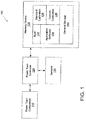
- the power train subsystem 100 may include a power train component 110, a power train controller 120 and associated memory device 130.
- the power train component 110 may include components of a motor vehicle used to generate power and/or transfer power to a drive assembly of the motorized vehicle.
- the power train component 110 may include an engine, transmission, transfer box, torque converter, and/or gear box.
- the power train controller 110 may be coupled to the power train component 120 to control the power train component 120 via one or more control signals.
- the power train controller 110 may be further coupled to one or more sensors 135 in order to receive signals indicative of the operation of the power train component 120.
- some or all of the sensors 135 may be integrated with the power train component 120 and/or some or all of the sensors 135 may be distributed throughout a vehicle in which the power train component 120 resides.
- the memory device 130 may be coupled to the power train controller 120.
- the memory device 120 may include boot code 132, application software 134, standard calibration parameters 136, and custom calibration parameters 138.
- the boot code 132 may include an operating system, drivers and other code which the power train controller 120 (e.g. ECU 240 or TCM 250) may execute in response to being powered up.
- the boot code 132 may provide an execution environment upon which the application software 134 may execute.
- the application software 134 may provide commands for controlling a class or range of power train components. For example, the application software 134 may provide commands for controlling one or more transmission models and/or one or more engine models.
- the power train controller 120 may control the operation of the power train component based upon signals from sensors 135.
- the power train controller 120 in response to executing commands of the application software 134 may control the power train component 110 in accordance with standard calibration parameters 136 and custom calibration parameters 138.
- the power train controller 110 and the power train component 120 may be utilized in a wide variety of applications.
- the standard calibration parameters 136 provide various calibration data, constants, etc. which remain the same regardless of the application in which the power train controller 110 and power train component 120 are used.
- the custom calibration parameters 138 however provide various calibration data, constants, etc. which vary depending upon the application in which the power train controller 110 and power train component 120 are used.
- the memory device 130 may be programmed to include the boot code 132, application software 134 and standard calibration parameters 136 to obtain a partially programmed power train subsystem 100 that may be used in a wide variety of applications. Such a partially programmed power train subsystem 100 may be later programmed with custom calibration parameters 138 to obtain a fully programmed power train subsystem 100 once its determined to which application the power train subsystem 100 is destined.
- the memory device 130 may also include general storage 140 for the application software 134.
- the application software 134 may permit the storage and retrieval of customer modifiable constants (CMC) to and from the general storage 140.
- CMC customer modifiable constants
- a technician, vehicle manufacturer, etc. may use the CMCs to trim the operation of a fully programmed engine subassembly 220 and/or a fully programmed transmission subassembly 230.
- the application software 134 may store diagnostic codes in response to a detected event.
- the application software 134 may store freeze frame data comprising the capture of multiple operating parameters over a period of time in response to a detected event or in response to a request received from a technician.
- the application software 134 may permit the capture and/or retrieval of data from various components connected to a vehicle network.
- the application software 134 may permit retrieval of such saved diagnostic codes, freeze frame data, and/or other component data in order to aid a technician in troubleshooting a malfunction or to aid technician in identifying operating characteristics indicative of a potential malfunction in the future.
- the application software 134 may further permit the storage and retrieval of service manuals for one or more components of the vehicle, service records for one or more components of the vehicle, required service tools, wiring diagrams, and an as-built parts list for one or more components of the vehicle.
- the service manuals, service records, required service tools, wiring diagrams, and as-built part lists may aid a technician in determining which parts are in need of service and which parts have been serviced in the past. Moreover, such information may further aid the technician in identifying parts of the vehicle which have been replaced with parts not in conformance with parts of the vehicle as originally built.
- the motor vehicle 200 may include a power train 210, drive assembly 250, and operator interface 260.
- the power train 210 includes a first power train subsystem 220 and a second power train subsystem 230.
- the first power train subsystem 220 includes an engine 222, an engine control unit (ECU) 224, and memory device 226.
- the ECU 224 may be coupled to the engine 222 to control the engine 222.
- the ECU 224 may be further connected to various sensors 135 ( FIG. 1 ) of the motor vehicle 200 that provide the ECU 224 with various operating conditions associated with operation of the engine 222.
- the second power train subsystem 230 includes a transmission 232, transmission control module (TCM) 234 and memory device 236.
- the TCM 234 may be coupled to the transmission 232 to control the transmission 232.
- the TCM 234 may be further connected to various sensors 135 ( FIG. 1 ) that provide the TCM 234 with various operating conditions associated with operation of the transmission 232.
- the transmission 232 may provide a torque-speed conversion from the generally higher speed engine 222 to a slower but more forceful output such as the drive assembly 250.
- the drive assembly 250 may include drive wheels, caterpillar tracks, propels, etc. that impart the motor vehicle 200 with locomotion when driven by the engine 222 via the transmission 232.
- the engine 222 is coupled to an input shaft 242 of the transmission 232 to provide power to the transmission 232.
- An output shaft 244 of the transmission 232 is coupled to the drive assembly 250 to provide power to the drive assembly 250.
- the ECU 224 and TCM 234 may be implemented using analog and/or digital circuit components.
- the ECU 224 and the TCM 234 each include a processor such as a microcontroller or microprocessor.
- the ECU 224 and TCM 234 each have one or more associated memory devices 226, 236 that store instructions to be respectively executed by the ECU 224 and the TCM 234.
- the memory device 226, 236 may include programmable read only memory devices, flash memory device, random access memory devices, and/or other storage devices that store instructions to be executed and data to be processed by the ECU 224 and the TCM 234.
- the motor vehicle 200 may further include operator controls 260.
- the operator controls 260 may include various levers, switches, pedals, buttons, wheels, dials, etc. which an operator of the motor vehicle 200 may actuate in order to control operation of the motor vehicle 200.
- the operator controls 260 may further include various output devices such as needles, digital outputs, displays, etc. that the operator may monitor in order to confirm operation of the motor vehicle 200.
- the memory device 226 may be partially programmed to include boot code 132, application software 134, and standard calibration parameters 136 to configure the ECU 224 and engine 222 for a particular range of applications.
- Custom calibration parameters 138 may later be stored in the memory device 226 to obtain a fully programmed engine subsystem 220 which has been customized for a particular application.
- the memory device 226 may be programmed with standard calibration parameters 136 that define a hardware characterization for the engine subsystem 220 (e.g. define a combustion model as a function of boost and fuel injected), that define a communication datalink infrastructure (e.g. protocols supported, message formats, etc.), and that define diagnostic and failure modes.
- the memory device 226 may also be programmed with standard calibration parameter 136 that define anti-abuse algorithms for the engine subsystem 220, that define fuel to air ratio algorithms, that define emissions control parameters, that define odometer parameters, and that define sensor and actuator parameters (e.g. calibration of oxygen sensor outputs to measurement values).
- the memory device 226 may be programmed to include custom calibration parameters that define torque and horsepower ratings and that define communication datalink selections (e.g. protocols selected, devices from which to receive messages, etc.).
- the memory device 226 may further store custom calibration parameters that enable/disable general purpose input/output functions (e.g. the cruise control is ON and only active above the specified road speed).
- the memory device 226 may also store custom calibration parameters that define engine accessory features (e.g. engine brake, road speed governor, idle shutdown, PTO (power take-off) control, governor type, etc.).
- the memory device 236 may be partially programmed to include boot code 132, application software 134, and standard calibration parameters 136 to configure the TCM 234 and transmission 232 for a particular range of applications.
- Custom calibration parameters 138 may later be stored in the memory device 236 to obtain a fully programmed transmission subsystem 230 which has been customized for a particular application.
- the memory device 236 may be programmed with standard calibration parameters 136 that define a hardware characterization of the transmission subsystem 230 (e.g. oil flow as a function of temperature), that define communication datalink infrastructure (protocols supported, message formats, etc.), and that define diagnostic and failure modes.
- the memory device 226 may also be programmed with standard calibration parameter 136 for the transmission subsystem 230 that define anti-abuse algorithms, that define base values of learning parameters (e.g. pressures and volumes), and that define general purpose input/output function design criteria.
- Standard calibration parameters 136 may also be stored on the memory device 226 that define for the transmission subsystem 230 shift times (e.g. how long to slip clutches) and that define for the transmission subsystem 230 sensor and actuator calibration (e.g. correlating a sensor output such as a voltage to a measured value such as temperature).
- the memory device 226 may be programmed to include custom calibration parameters that define shift schedules (e.g. engine speeds at which to upshift) and that define communication datalink selections (e.g. protocols selected, devices from which to receive messages, etc.).
- the memory device 226 may further store custom calibration parameters that define general purpose input/output function enables/disables (e.g. output shaft retarder is ON and only active above the specified road speed).
- the memory device 226 may also store custom calibration parameters 138 that enable/disable integrated vehicle functions (e.g. variable modulated main, cab warm-up mode, vehicle acceleration control, etc.).
- FIG. 3 another embodiment of a vehicle 300 is shown.
- the vehicle 300 is similar to the vehicle 200 of FIG. 2 .
- the ECU 240 is internal to or otherwise integrated with the engine 310 instead of being external to the engine 210 as shown in the vehicle 200 FIG. 2 .
- the TCM 250 is internal to or otherwise integrated with the transmission 320 instead of being external to the engine 210 as shown in the vehicle 200 of FIG. 2 .
- the ECU 240 and TCM 250 may be integrated into the respective power train components of the vehicle 300, the associated memory devices 245, 255 of vehicle 300 are still maintained external to the respective power train components to permit easy programming and/or replacement.
- FIG. 4 yet another embodiment of a vehicle 400 is shown.
- the vehicle 400 is similar to the vehicle 300 of FIG. 3 .
- the memory device 426 associated with the ECU 424 is affixed to or otherwise integrated with the ECU 424.
- the ECU 424 is internal to or otherwise integrated with the engine 422.
- the memory device 436 associated with the TCM 434 is affixed to or otherwise integrated with the TCM 434.
- the TCM 434 in turn is internal to or otherwise integrated with the transmission 432.
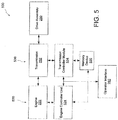
- FIG. 5 depicts yet another embodiment of a vehicle 500.
- the vehicle 500 is similar to the vehicles 200, 300 and 400 of FIGS. 2-4 .
- the ECU 524 and TCM 534 share a memory device 536 instead of each having a separate memory device as shown in FIGS. 2-4 .
- the vehicle 500 shows the memory device 536 externally coupled to the ECU 524 and the TCM 534.
- the memory device 536 may be affixed to or otherwise integrated with either the ECU 524 or the TCM 534 in a manner similar to the vehicle 400 of FIG. 4 .
- the ECU 524 and/or the TCM 534 may be internal to or otherwise integrated with their respective power train component 522, 532 in a manner similar to the vehicles 300, 400 of FIGS. 2 and 3 .
- the memory device 130 may be coupled to the power train controller 120 using a number of different techniques.
- the memory device 130 may be removably coupled a connector 610 of a wiring harness 620 which is used to operatively couple the TCM 334 of the transmission 332 to other components of the vehicle 300 such as the sensors 135 and operator interface 260.
- the memory device 130 may alternatively be removably coupled to a memory slot or connecter 710 of a shift selector 720 of the operator interface 260 as shown in FIG. 7 .
- FIG. 8 shows yet another location for the memory device 130. As shown, the memory device 130 may be removably coupled to connector 810 of a fuse block 820 of the vehicle.
- FIGS. 6-10 show the memory device 130 removably coupled to a connector thus permitting the removal of the memory device 130 for programming and/or replacement.
- the memory device 130 may be affixed to the wiring harness 620, shift selector 720, fuse block 820, and/or other location of the vehicle.
- the wiring harness 620, shift selector 720, fuse block 820, and/or other component of the vehicle may have a connector 630 for receiving a programming device 640 as shown in FIG. 6 .
- the programming device 640 in one embodiment may program a partially programmed memory device 130 (e.g.
- the programming device 640 in one embodiment may comprise a self powered portable device which may be simply attached to connector 630.
- the programming device 640 may include a user interface 642 such as a button or other user input device which may be actuated in order to initiate programming of the memory device 130.
- the programming device 640 in another embodiment may detect being coupled to the connector 630 and may automatically initiate programming of the memory device 130 upon detection.
- the user interface 642 of programming device 640 may also include an indicator (e.g. a lamp, LED, LCD, speaker) via which the programming device 640 may audibly and/or visually signal completion of the programming of the memory device 130.
- the programming device 640 may instead include a more sophisticated user interface 642 such a display, keypad, etc.
- the programming device 640 may display a progress indicator, via which a technician may select from among several custom calibration parameter sets for use in programming a power train subsystem or component thereof, and/or via which a technician may alter individual custom calibration parameters 138 of a memory device 130.
- the above disclosure identified embodiments in which memory devices 130, 226, 326, 336, 426, 436, 536 were positioned at various location in the vehicle 100. It should be appreciated other embodiments may place a memory device 130 at positions in the vehicle 100 other than those positions identified above.
- the memory device 130 may be positioned anywhere in and/or on the vehicle 100 that has access to a vehicular network (e.g. a CAN network) and the power train components coupled to the vehicular network.
- the above embodiment of the programming device 640 indicates the programming device 640 is coupled to the memory device 130 via the connector 630 of the wiring harness 620.
- the programming device 640 may be coupled to the memory device 130 via other mechanisms.
- the programming device 640 may be directly connected to the memory device 130 via a connector of the memory device 130.
- the programming device 640 may be coupled to a vehicular network of the vehicle 100 and may program the memory device 130 via the vehicular network.
- a manufacturer at block 910 may partially program several power train controllers 120 for a class or range of power train components 110.
- a transmission manufacturer may partially program the memory device 236 of several transmission control modules 234 with boot code 132, application software 134, and standard calibration parameters 136 thus configuring the transmission control modules 234 for use with a particular transmission 232 or class of transmissions 232 that may be used in a range of vehicular applications.
- the manufacturer may receive a request from a customer such as a parts distributor, vehicle manufacturer, etc. for a certain number of transmission subsystems fully programmed for a particular vehicular application.
- the manufacturer at block 930 may retrieve or otherwise define custom calibration parameters 138 which configure the partially programmed transmission control modules 234 for the requested vehicular application.
- the transmission manufacturer may maintain a database of predefined custom calibration parameters 138 for each supported vehicular application and therefore need only retrieve the appropriate custom calibration parameters 138 for the requested vehicular application.
- the transmission manufacturer may manually define the custom calibration parameters 138 in order to satisfy a custom vehicular application specified by the customer.
- the manufacturer at block 940 may fully program a number of power train controllers 120 which had been previously partially programmed to obtain the requested number of power train controller 120 which have been fully programmed for the requested vehicular application.
- the manufacturer may store the appropriate custom calibration parameters 138 for the requested vehicular application in the associated memory device 130 for each power train controller 120 being programmed for the customer.
- the transmission manufacturer may store the retrieved or otherwise defined custom calibration parameters 138 in the associated memory device 236 for each transmission control module 234 in order to obtain the requested number of fully programmed transmission control modules 234 for the requested vehicular application.
- the manufacturer may ship the fully programmed power train controllers 120 to the customer.
- the manufacturer may ship to the customer engine control units 224, 324, 424, 524 and/or transmission control modules 234, 334, 434, 534 which have been fully programmed for the vehicular application requested by the customer.
- the partial programming of block 910 configures the power train controllers 120 for a range of applications.
- the manufacturer may fulfill several customer requests (i.e. steps 920-950) without partially programming additional power train controllers 120 even though the requests may span several different vehicular applications since the power train controllers 120 are not customized for a particular vehicular application until fully programmed at block 940.
- the partially programmed power train controllers 120 may ultimate end up with different customers which requested power train controllers 120 for different vehicular applications.
- FIG. 10 another embodiment of a method 1000 for programming power train controllers 120 such as engine control units 224, 323, 424 and transmission control modules 234, 334, 434 is shown.
- the manufacturer may receive a request from a customer such as a parts distributor, vehicle manufacturer, etc. for a certain number of power train subsystems which have been partially programmed for a particular vehicular application. Further, the manufacturer at block 1030 may ship the requested partially programmed power train subsystems to the customer.
- a manufacturer at block 1020 may partially program power train controllers 120 and/or select from inventory previously programmed power train controllers 120 for requested range or class of vehicular application.
- a transmission manufacturer may partially program the memory device 236 of several transmission control modules 234 with boot code 132, application software 134, and standard calibration parameters 136 thus configuring the transmission control modules 234 for use with a particular transmission 232 or class of transmissions 232 that may used in a range of vehicular applications.
- the manufacturer may ship the partially programmed power train controllers 120 to the customer.
- the manufacturer may ship to the customer engine control units 224, 324, 424, 524 and/or transmission control modules 234, 334, 434, 534 which have been partially programmed for the class or range of vehicular applications requested by the customer.
- the customer may retrieve or otherwise define custom calibration parameters 138 which configure the partially programmed transmission control modules 234 for a particular vehicular application.
- the customer may maintain separate programming devices 645 for each vehicular application. In such a case, the customer may simply select an appropriate programming device 645 for the vehicular application.
- the customer may have a programming device 645 suitable for fully programming power train subsystems for a range of vehicular applications. In such a case, the customer may select or otherwise define the appropriate custom calibration parameters 138 using an interface of the programming device 645.
- the customer may program the power train subsystem (e.g. memory devices associated with ECU 224 or TCM 234) with the selected custom calibration parameters for the vehicular application.
- the customer may fully program the power train subsystem prior to installing the power train subsystem in a corresponding vehicle 200, 300, 400, 500.
- the customer may fully program the power train subsystem after the power train subsystem is installed in the corresponding vehicle 200, 300, 400, 500.
- the partial programming of block 1020 configures the power train controllers 120 for a range of applications.
- the customer may use the partially programmed power train controller 120 in several vehicular applications (i.e. steps 1040-1050) without ordering further partially programming power train controllers 120.
- the power train controllers 120 in one embodiment are not customized for a particular vehicular application until fully programmed at block 1050. Accordingly, the partially programmed power train controllers 120 ordered at block 1010 may ultimate end up in a variety of vehicular applications.
Landscapes
- Engineering & Computer Science (AREA)
- Mechanical Engineering (AREA)
- Automation & Control Theory (AREA)
- Transportation (AREA)
- Human Computer Interaction (AREA)
- Chemical & Material Sciences (AREA)
- Combustion & Propulsion (AREA)
- General Engineering & Computer Science (AREA)
- Physics & Mathematics (AREA)
- General Physics & Mathematics (AREA)
- Computer Hardware Design (AREA)
- Theoretical Computer Science (AREA)
- Mathematical Physics (AREA)
- Control Of Transmission Device (AREA)
- Electric Propulsion And Braking For Vehicles (AREA)
Applications Claiming Priority (2)
| Application Number | Priority Date | Filing Date | Title |
|---|---|---|---|
| US14417909P | 2009-01-13 | 2009-01-13 | |
| EP10731960.0A EP2376811B1 (fr) | 2009-01-13 | 2010-01-07 | Sous-système d'une chaîne cinématique et procédé d'adaption d'une transmission d'un véhicule automobile |
Related Parent Applications (2)
| Application Number | Title | Priority Date | Filing Date |
|---|---|---|---|
| EP10731960.0A Division-Into EP2376811B1 (fr) | 2009-01-13 | 2010-01-07 | Sous-système d'une chaîne cinématique et procédé d'adaption d'une transmission d'un véhicule automobile |
| EP10731960.0A Division EP2376811B1 (fr) | 2009-01-13 | 2010-01-07 | Sous-système d'une chaîne cinématique et procédé d'adaption d'une transmission d'un véhicule automobile |
Publications (1)
| Publication Number | Publication Date |
|---|---|
| EP3021008A1 true EP3021008A1 (fr) | 2016-05-18 |
Family
ID=42340058
Family Applications (2)
| Application Number | Title | Priority Date | Filing Date |
|---|---|---|---|
| EP10731960.0A Not-in-force EP2376811B1 (fr) | 2009-01-13 | 2010-01-07 | Sous-système d'une chaîne cinématique et procédé d'adaption d'une transmission d'un véhicule automobile |
| EP15201385.0A Withdrawn EP3021008A1 (fr) | 2009-01-13 | 2010-01-07 | Procédé d'adaptation d'une transmission |
Family Applications Before (1)
| Application Number | Title | Priority Date | Filing Date |
|---|---|---|---|
| EP10731960.0A Not-in-force EP2376811B1 (fr) | 2009-01-13 | 2010-01-07 | Sous-système d'une chaîne cinématique et procédé d'adaption d'une transmission d'un véhicule automobile |
Country Status (6)
| Country | Link |
|---|---|
| US (2) | US9216744B2 (fr) |
| EP (2) | EP2376811B1 (fr) |
| KR (1) | KR101748446B1 (fr) |
| CN (1) | CN102333975B (fr) |
| CA (1) | CA2749530C (fr) |
| WO (1) | WO2010083090A1 (fr) |
Families Citing this family (13)
| Publication number | Priority date | Publication date | Assignee | Title |
|---|---|---|---|---|
| CN102333975B (zh) | 2009-01-13 | 2015-07-22 | 艾里逊变速箱公司 | 动力传动控制器以及相关存储设备 |
| DE102010035201A1 (de) * | 2010-08-24 | 2012-03-01 | Gm Global Technology Operations Llc (N.D.Ges.D. Staates Delaware) | Informationsträger, Fahrzeug mit Informationsträger sowie System zur Unterstützung von Rettungskräften bei der Bergung von Insassen aus einem verunglückten Fahrzeug |
| US8788424B2 (en) | 2011-04-22 | 2014-07-22 | Allison Transmission, Inc. | Method of setting transmission shift points in real-time based upon an engine performance curve |
| EP2699824B1 (fr) * | 2011-04-22 | 2020-01-22 | Allison Transmission, Inc. | Procédé de définition de points de passage de rapport de transmission en temps réel sur base d'une courbe de performance du moteur |
| DE102012202323A1 (de) * | 2012-02-16 | 2013-08-22 | Jungheinrich Aktiengesellschaft | Gewerbliches Fahrzeug, insbesondere Gabelstapler oder Flurförderzeug, mit einem fahrzeugseitig fest angebrachten Datenspeicher in Zuordnung zu einer parametrierbaren elektronischen Steueranordnung |
| AU2014237795B2 (en) * | 2013-03-15 | 2017-04-06 | Allison Transmission, Inc. | System and method for balancing states of charge of energy storage modules in hybrid vehicles |
| US20160131067A1 (en) * | 2013-05-29 | 2016-05-12 | International Engine Intellectual Property Company, Llc | Automated Assembly of ECU Calibrations |
| WO2015021997A1 (fr) * | 2013-08-14 | 2015-02-19 | Volvo Truck Corporation | Procédé d'étalonnage automatique de transmission automatique |
| CN105516853B (zh) * | 2014-09-26 | 2019-04-30 | 惠州市德赛西威汽车电子股份有限公司 | 一种车载娱乐系统音效参数调试装置及方法 |
| CN104455375B (zh) * | 2014-11-27 | 2017-02-01 | 盛瑞传动股份有限公司 | 自动变速器控制单元档位自学习控制方法和装置 |
| JP7338584B2 (ja) * | 2020-08-07 | 2023-09-05 | トヨタ自動車株式会社 | 異常判定装置 |
| EP4281861B1 (fr) * | 2021-01-21 | 2025-06-04 | Audi AG | Procédé de réglage de données de spécification de spécifications de véhicule dans plusieurs unités de commande d'un véhicule et unité de commande pour un véhicule et véhicule |
| US11572947B2 (en) * | 2021-06-07 | 2023-02-07 | Caterpillar Paving Products Inc. | Gear shift calibration |
Citations (6)
| Publication number | Priority date | Publication date | Assignee | Title |
|---|---|---|---|---|
| US5798647A (en) * | 1996-05-06 | 1998-08-25 | Chrysler Corporation | Diagnostic test controller apparatus |
| US20020116093A1 (en) * | 2001-02-21 | 2002-08-22 | Aldrich William Leonard | Methods and apparatus for configuring an automobile electronic control module |
| US20030078699A1 (en) * | 2000-09-07 | 2003-04-24 | Klaus Harms | Electronic system for a vehicle and system layer for operational functions |
| DE10234063A1 (de) * | 2002-07-26 | 2004-02-19 | Audi Ag | Verfahren zum variantenspezifischen Programmieren eines Programm- und Datenspeichers eines Steuergeräts, insbesondere eines Steuergeräts eines Kraftfahrzeugs |
| US20070250254A1 (en) * | 2006-03-24 | 2007-10-25 | Mitsubishi Electric Corporation | On-vehicle control apparatus |
| DE102007015355A1 (de) * | 2007-03-30 | 2008-10-02 | Zf Friedrichshafen Ag | Steuerungsvorrichtung eines automatisierten Stufenschaltgetriebes |
Family Cites Families (18)
| Publication number | Priority date | Publication date | Assignee | Title |
|---|---|---|---|---|
| US5541840A (en) * | 1993-06-25 | 1996-07-30 | Chrysler Corporation | Hand held automotive diagnostic service tool |
| US5481170A (en) * | 1993-08-11 | 1996-01-02 | Eaton Corporation | Method and apparatus for controlling shift force in an automated mechanical transmission |
| US20050192727A1 (en) * | 1994-05-09 | 2005-09-01 | Automotive Technologies International Inc. | Sensor Assemblies |
| US7103460B1 (en) * | 1994-05-09 | 2006-09-05 | Automotive Technologies International, Inc. | System and method for vehicle diagnostics |
| US7421321B2 (en) * | 1995-06-07 | 2008-09-02 | Automotive Technologies International, Inc. | System for obtaining vehicular information |
| DE19713423C5 (de) * | 1996-04-03 | 2015-11-26 | Schaeffler Technologies AG & Co. KG | Vorrichtung und Verfahren zur Betätigung eines Getriebes |
| US6612386B2 (en) * | 2001-05-30 | 2003-09-02 | General Motors Corporation | Apparatus and method for controlling a hybrid vehicle |
| US7379801B2 (en) | 2004-11-01 | 2008-05-27 | Hypertech, Inc. | Programmable automotive computer system |
| EP1869609A2 (fr) * | 2005-04-08 | 2007-12-26 | Ricardo, Inc. | Outil de reglage du chassis et du groupe motopropulseur d'un vehicule pour optimiser la trajectoire sur une voie et la vitesse |
| US7590768B2 (en) * | 2005-09-23 | 2009-09-15 | Joseph Gormley | Control and interconnection system |
| JP4692231B2 (ja) * | 2005-11-04 | 2011-06-01 | 株式会社デンソー | 車両用の電子制御装置 |
| US20070260373A1 (en) * | 2006-05-08 | 2007-11-08 | Langer William J | Dynamic vehicle durability testing and simulation |
| US20070260438A1 (en) * | 2006-05-08 | 2007-11-08 | Langer William J | Vehicle testing and simulation using integrated simulation model and physical parts |
| US20070260372A1 (en) * | 2006-05-08 | 2007-11-08 | Langer William J | Dynamic vehicle suspension system testing and simulation |
| US7885748B2 (en) * | 2006-09-13 | 2011-02-08 | Gm Global Technology Operations, Inc. | Virtual accelerometer |
| EP1935712A1 (fr) * | 2006-12-22 | 2008-06-25 | Nederlandse Organisatie voor Toegepast-Natuuurwetenschappelijk Onderzoek TNO | Système et procédé pour véhicule |
| US7694555B2 (en) * | 2007-03-27 | 2010-04-13 | Gm Global Technology Operations, Inc. | Brake pad prognosis system |
| CN102333975B (zh) | 2009-01-13 | 2015-07-22 | 艾里逊变速箱公司 | 动力传动控制器以及相关存储设备 |
-
2010
- 2010-01-07 CN CN201080009644.7A patent/CN102333975B/zh active Active
- 2010-01-07 US US13/144,243 patent/US9216744B2/en active Active
- 2010-01-07 CA CA2749530A patent/CA2749530C/fr active Active
- 2010-01-07 WO PCT/US2010/020361 patent/WO2010083090A1/fr not_active Ceased
- 2010-01-07 EP EP10731960.0A patent/EP2376811B1/fr not_active Not-in-force
- 2010-01-07 EP EP15201385.0A patent/EP3021008A1/fr not_active Withdrawn
- 2010-01-07 KR KR1020117018791A patent/KR101748446B1/ko active Active
-
2015
- 2015-12-22 US US14/978,492 patent/US9970532B2/en active Active
Patent Citations (6)
| Publication number | Priority date | Publication date | Assignee | Title |
|---|---|---|---|---|
| US5798647A (en) * | 1996-05-06 | 1998-08-25 | Chrysler Corporation | Diagnostic test controller apparatus |
| US20030078699A1 (en) * | 2000-09-07 | 2003-04-24 | Klaus Harms | Electronic system for a vehicle and system layer for operational functions |
| US20020116093A1 (en) * | 2001-02-21 | 2002-08-22 | Aldrich William Leonard | Methods and apparatus for configuring an automobile electronic control module |
| DE10234063A1 (de) * | 2002-07-26 | 2004-02-19 | Audi Ag | Verfahren zum variantenspezifischen Programmieren eines Programm- und Datenspeichers eines Steuergeräts, insbesondere eines Steuergeräts eines Kraftfahrzeugs |
| US20070250254A1 (en) * | 2006-03-24 | 2007-10-25 | Mitsubishi Electric Corporation | On-vehicle control apparatus |
| DE102007015355A1 (de) * | 2007-03-30 | 2008-10-02 | Zf Friedrichshafen Ag | Steuerungsvorrichtung eines automatisierten Stufenschaltgetriebes |
Also Published As
| Publication number | Publication date |
|---|---|
| EP2376811B1 (fr) | 2016-06-29 |
| US9216744B2 (en) | 2015-12-22 |
| CA2749530C (fr) | 2016-12-20 |
| EP2376811A4 (fr) | 2013-11-13 |
| KR20110131178A (ko) | 2011-12-06 |
| US9970532B2 (en) | 2018-05-15 |
| KR101748446B1 (ko) | 2017-06-16 |
| US20120143447A1 (en) | 2012-06-07 |
| CN102333975B (zh) | 2015-07-22 |
| WO2010083090A1 (fr) | 2010-07-22 |
| EP2376811A1 (fr) | 2011-10-19 |
| CN102333975A (zh) | 2012-01-25 |
| US20160109018A1 (en) | 2016-04-21 |
| CA2749530A1 (fr) | 2010-07-22 |
Similar Documents
| Publication | Publication Date | Title |
|---|---|---|
| US9970532B2 (en) | Power train controller and associated memory device | |
| US8638207B2 (en) | Modular vehicular diagnostic tool | |
| EP2112492B1 (fr) | Liste d'exigences de test pour tests de diagnostic | |
| EP1569176B1 (fr) | Système opérateur et méthode d'identification d'état au moyen de fichiers | |
| EP2088048A1 (fr) | Procédé et système pour la configuration d'un système de contrôle électronique pour le contrôle du fonctionnement d'un composant au moins d'un véhicule | |
| US5365436A (en) | Electronic management system for heavy-duty trucks | |
| US20160343177A1 (en) | Real time vehicle diagnosis system | |
| US7135964B2 (en) | Data link connector (DLC) driven display | |
| MX2007011383A (es) | Sistema y metodo para sistema indicador modular para vehiculos e iluminacion. | |
| US11428175B2 (en) | Method of offering finely calibrated engine speed control to a large number of diverse power take-off (PTO) applications | |
| US6347272B2 (en) | Vehicle passing speed timer | |
| EP2764343B1 (fr) | Méthode et procédé de diagnostic de panne d'une fonction de superstructure de véhicules | |
| EP1975386A2 (fr) | Embrayage de ventilateur intelligent | |
| CN112005212A (zh) | 用于启动变速器控制模块的空中编程的系统和方法 | |
| US20080161994A1 (en) | Method and system for autogenerating static fault code data based on a unified summary table for heavy duty diesel engines | |
| JP4685211B2 (ja) | 車両内の駆動シーケンスを制御する制御ユニットの駆動方法及び駆動装置 | |
| EP2574517B1 (fr) | Dispositif de commande de véhicule, dispositif de surveillance d'informations de véhicule, système de surveillance d'informations de véhicule et procédé de commande de véhicule | |
| CN201745445U (zh) | 非公路自卸车can总线组合仪表 | |
| US20080097665A1 (en) | Method for the maintenance of application data of a vehicle component of a motor vehicle | |
| CN112172548B (zh) | 一种用于车辆的动力系统的控制方法、动力系统及车辆 | |
| JP5288128B2 (ja) | 計器の駆動装置 | |
| JP2003049704A (ja) | 車両仕様識別装置 | |
| CN1980818A (zh) | 提供用于在机动车中用的传动系的表征预定事件的数据的方法 |
Legal Events
| Date | Code | Title | Description |
|---|---|---|---|
| PUAI | Public reference made under article 153(3) epc to a published international application that has entered the european phase |
Free format text: ORIGINAL CODE: 0009012 |
|
| AC | Divisional application: reference to earlier application |
Ref document number: 2376811 Country of ref document: EP Kind code of ref document: P |
|
| AK | Designated contracting states |
Kind code of ref document: A1 Designated state(s): AT BE BG CH CY CZ DE DK EE ES FI FR GB GR HR HU IE IS IT LI LT LU LV MC MK MT NL NO PL PT RO SE SI SK SM TR |
|
| STAA | Information on the status of an ep patent application or granted ep patent |
Free format text: STATUS: THE APPLICATION HAS BEEN PUBLISHED |
|
| STAA | Information on the status of an ep patent application or granted ep patent |
Free format text: STATUS: THE APPLICATION IS DEEMED TO BE WITHDRAWN |
|
| 18D | Application deemed to be withdrawn |
Effective date: 20161119 |