EP3021012A1 - Procede de commande et de reglage d'une chaine cinematique - Google Patents
Procede de commande et de reglage d'une chaine cinematique Download PDFInfo
- Publication number
- EP3021012A1 EP3021012A1 EP15190951.2A EP15190951A EP3021012A1 EP 3021012 A1 EP3021012 A1 EP 3021012A1 EP 15190951 A EP15190951 A EP 15190951A EP 3021012 A1 EP3021012 A1 EP 3021012A1
- Authority
- EP
- European Patent Office
- Prior art keywords
- gas
- pressure accumulator
- pressure
- temperature
- actual
- Prior art date
- Legal status (The legal status is an assumption and is not a legal conclusion. Google has not performed a legal analysis and makes no representation as to the accuracy of the status listed.)
- Withdrawn
Links
Images

Classifications
-
- F—MECHANICAL ENGINEERING; LIGHTING; HEATING; WEAPONS; BLASTING
- F16—ENGINEERING ELEMENTS AND UNITS; GENERAL MEASURES FOR PRODUCING AND MAINTAINING EFFECTIVE FUNCTIONING OF MACHINES OR INSTALLATIONS; THERMAL INSULATION IN GENERAL
- F16H—GEARING
- F16H61/00—Control functions within control units of change-speed- or reversing-gearings for conveying rotary motion ; Control of exclusively fluid gearing, friction gearing, gearings with endless flexible members or other particular types of gearing
- F16H61/38—Control of exclusively fluid gearing
- F16H61/40—Control of exclusively fluid gearing hydrostatic
- F16H61/4078—Fluid exchange between hydrostatic circuits and external sources or consumers
- F16H61/4096—Fluid exchange between hydrostatic circuits and external sources or consumers with pressure accumulators
-
- B—PERFORMING OPERATIONS; TRANSPORTING
- B60—VEHICLES IN GENERAL
- B60K—ARRANGEMENT OR MOUNTING OF PROPULSION UNITS OR OF TRANSMISSIONS IN VEHICLES; ARRANGEMENT OR MOUNTING OF PLURAL DIVERSE PRIME-MOVERS IN VEHICLES; AUXILIARY DRIVES FOR VEHICLES; INSTRUMENTATION OR DASHBOARDS FOR VEHICLES; ARRANGEMENTS IN CONNECTION WITH COOLING, AIR INTAKE, GAS EXHAUST OR FUEL SUPPLY OF PROPULSION UNITS IN VEHICLES
- B60K6/00—Arrangement or mounting of plural diverse prime-movers for mutual or common propulsion, e.g. hybrid propulsion systems comprising electric motors and internal combustion engines
- B60K6/08—Prime-movers comprising combustion engines and mechanical or fluid energy storing means
- B60K6/12—Prime-movers comprising combustion engines and mechanical or fluid energy storing means by means of a chargeable fluidic accumulator
-
- B—PERFORMING OPERATIONS; TRANSPORTING
- B60—VEHICLES IN GENERAL
- B60K—ARRANGEMENT OR MOUNTING OF PROPULSION UNITS OR OF TRANSMISSIONS IN VEHICLES; ARRANGEMENT OR MOUNTING OF PLURAL DIVERSE PRIME-MOVERS IN VEHICLES; AUXILIARY DRIVES FOR VEHICLES; INSTRUMENTATION OR DASHBOARDS FOR VEHICLES; ARRANGEMENTS IN CONNECTION WITH COOLING, AIR INTAKE, GAS EXHAUST OR FUEL SUPPLY OF PROPULSION UNITS IN VEHICLES
- B60K6/00—Arrangement or mounting of plural diverse prime-movers for mutual or common propulsion, e.g. hybrid propulsion systems comprising electric motors and internal combustion engines
- B60K6/20—Arrangement or mounting of plural diverse prime-movers for mutual or common propulsion, e.g. hybrid propulsion systems comprising electric motors and internal combustion engines the prime-movers consisting of electric motors and internal combustion engines, e.g. HEVs
- B60K6/22—Arrangement or mounting of plural diverse prime-movers for mutual or common propulsion, e.g. hybrid propulsion systems comprising electric motors and internal combustion engines the prime-movers consisting of electric motors and internal combustion engines, e.g. HEVs characterised by apparatus, components or means specially adapted for HEVs
- B60K6/36—Arrangement or mounting of plural diverse prime-movers for mutual or common propulsion, e.g. hybrid propulsion systems comprising electric motors and internal combustion engines the prime-movers consisting of electric motors and internal combustion engines, e.g. HEVs characterised by apparatus, components or means specially adapted for HEVs characterised by the transmission gearings
- B60K6/365—Arrangement or mounting of plural diverse prime-movers for mutual or common propulsion, e.g. hybrid propulsion systems comprising electric motors and internal combustion engines the prime-movers consisting of electric motors and internal combustion engines, e.g. HEVs characterised by apparatus, components or means specially adapted for HEVs characterised by the transmission gearings with the gears having orbital motion
-
- B—PERFORMING OPERATIONS; TRANSPORTING
- B60—VEHICLES IN GENERAL
- B60K—ARRANGEMENT OR MOUNTING OF PROPULSION UNITS OR OF TRANSMISSIONS IN VEHICLES; ARRANGEMENT OR MOUNTING OF PLURAL DIVERSE PRIME-MOVERS IN VEHICLES; AUXILIARY DRIVES FOR VEHICLES; INSTRUMENTATION OR DASHBOARDS FOR VEHICLES; ARRANGEMENTS IN CONNECTION WITH COOLING, AIR INTAKE, GAS EXHAUST OR FUEL SUPPLY OF PROPULSION UNITS IN VEHICLES
- B60K6/00—Arrangement or mounting of plural diverse prime-movers for mutual or common propulsion, e.g. hybrid propulsion systems comprising electric motors and internal combustion engines
- B60K6/20—Arrangement or mounting of plural diverse prime-movers for mutual or common propulsion, e.g. hybrid propulsion systems comprising electric motors and internal combustion engines the prime-movers consisting of electric motors and internal combustion engines, e.g. HEVs
- B60K6/22—Arrangement or mounting of plural diverse prime-movers for mutual or common propulsion, e.g. hybrid propulsion systems comprising electric motors and internal combustion engines the prime-movers consisting of electric motors and internal combustion engines, e.g. HEVs characterised by apparatus, components or means specially adapted for HEVs
- B60K6/38—Arrangement or mounting of plural diverse prime-movers for mutual or common propulsion, e.g. hybrid propulsion systems comprising electric motors and internal combustion engines the prime-movers consisting of electric motors and internal combustion engines, e.g. HEVs characterised by apparatus, components or means specially adapted for HEVs characterised by the driveline clutches
- B60K6/387—Actuated clutches, i.e. clutches engaged or disengaged by electric, hydraulic or mechanical actuating means
-
- F—MECHANICAL ENGINEERING; LIGHTING; HEATING; WEAPONS; BLASTING
- F16—ENGINEERING ELEMENTS AND UNITS; GENERAL MEASURES FOR PRODUCING AND MAINTAINING EFFECTIVE FUNCTIONING OF MACHINES OR INSTALLATIONS; THERMAL INSULATION IN GENERAL
- F16H—GEARING
- F16H37/00—Combinations of mechanical gearings, not provided for in groups F16H1/00 - F16H35/00
- F16H37/02—Combinations of mechanical gearings, not provided for in groups F16H1/00 - F16H35/00 comprising essentially only toothed or friction gearings
- F16H37/06—Combinations of mechanical gearings, not provided for in groups F16H1/00 - F16H35/00 comprising essentially only toothed or friction gearings with a plurality of driving or driven shafts; with arrangements for dividing torque between two or more intermediate shafts
- F16H37/08—Combinations of mechanical gearings, not provided for in groups F16H1/00 - F16H35/00 comprising essentially only toothed or friction gearings with a plurality of driving or driven shafts; with arrangements for dividing torque between two or more intermediate shafts with differential gearing
- F16H37/0833—Combinations of mechanical gearings, not provided for in groups F16H1/00 - F16H35/00 comprising essentially only toothed or friction gearings with a plurality of driving or driven shafts; with arrangements for dividing torque between two or more intermediate shafts with differential gearing with arrangements for dividing torque between two or more intermediate shafts, i.e. with two or more internal power paths
- F16H37/084—Combinations of mechanical gearings, not provided for in groups F16H1/00 - F16H35/00 comprising essentially only toothed or friction gearings with a plurality of driving or driven shafts; with arrangements for dividing torque between two or more intermediate shafts with differential gearing with arrangements for dividing torque between two or more intermediate shafts, i.e. with two or more internal power paths at least one power path being a continuously variable transmission, i.e. CVT
- F16H2037/0866—Power-split transmissions with distributing differentials, with the output of the CVT connected or connectable to the output shaft
-
- F—MECHANICAL ENGINEERING; LIGHTING; HEATING; WEAPONS; BLASTING
- F16—ENGINEERING ELEMENTS AND UNITS; GENERAL MEASURES FOR PRODUCING AND MAINTAINING EFFECTIVE FUNCTIONING OF MACHINES OR INSTALLATIONS; THERMAL INSULATION IN GENERAL
- F16H—GEARING
- F16H47/00—Combinations of mechanical gearing with fluid clutches or fluid gearing
- F16H47/02—Combinations of mechanical gearing with fluid clutches or fluid gearing the fluid gearing being of the volumetric type
- F16H47/04—Combinations of mechanical gearing with fluid clutches or fluid gearing the fluid gearing being of the volumetric type the mechanical gearing being of the type with members having orbital motion
-
- Y—GENERAL TAGGING OF NEW TECHNOLOGICAL DEVELOPMENTS; GENERAL TAGGING OF CROSS-SECTIONAL TECHNOLOGIES SPANNING OVER SEVERAL SECTIONS OF THE IPC; TECHNICAL SUBJECTS COVERED BY FORMER USPC CROSS-REFERENCE ART COLLECTIONS [XRACs] AND DIGESTS
- Y02—TECHNOLOGIES OR APPLICATIONS FOR MITIGATION OR ADAPTATION AGAINST CLIMATE CHANGE
- Y02T—CLIMATE CHANGE MITIGATION TECHNOLOGIES RELATED TO TRANSPORTATION
- Y02T10/00—Road transport of goods or passengers
- Y02T10/60—Other road transportation technologies with climate change mitigation effect
- Y02T10/62—Hybrid vehicles
Definitions
- the present invention relates to a method for controlling and / or regulating a drive train according to the preamble of claim 1 and a drive train according to the preamble of claim 13.
- Motor vehicles with an internal combustion engine have a drive train for transmitting power from the internal combustion engine to at least one drive wheel.
- two drive wheels are generally driven by means of a differential gear on the motor vehicle.
- the internal combustion engine provides mechanical energy with a motor shaft, and by means of a power split transmission, this mechanical energy can be divided from the motor shaft to a first and second output shaft at the power split transmission.
- the first output shaft drives a mechanical drive sub-strand of the drive train, in which the mechanical energy is transmitted exclusively mechanically to the at least one drive wheel or the differential gear.
- the second drive shaft drives a hydraulic drive sub-strand and in the hydraulic drive sub-strand, a hydraulic transmission is integrated or installed, so that on the hydraulic drive sub-strand, the transmission of mechanical energy is also performed hydraulically.
- a pump which is driven by the second output shaft, and a hydraulic motor, which is driven by a hydraulic fluid from the pump.
- the hydraulic motor in turn drives the differential gear or the at least one with a drive shaft on the hydraulic motor or a hydraulic gear drive shaft Drive wheel on.
- the drive train to a pressure accumulator for pressure storage of hydraulic energy.
- the hydraulic fluid can be supplied not only to the hydraulic motor, but also a pressure accumulator for storing hydraulic energy. This stored in the pressure accumulator hydraulic energy can be used later by passing the hydraulic fluid from the pressure accumulator to the hydraulic motor for driving the at least one drive wheel or the differential gear.
- kinetic energy of the motor vehicle can be stored in the pressure accumulator as hydraulic energy.
- the pressure of the gas in the pressure accumulator and with a temperature sensor the temperature of the gas can be detected with a pressure sensor and from this the volume of the gas can be calculated.
- the actual pressure and the actual temperature of the gas change as a function of time.
- the pressure sensor detects the actual pressure as a measuring pressure with a first time delay of approximately 0.01 s and the temperature sensor detects the measuring temperature as the actual temperature with a second time delay of approximately 2 to 3 s.
- the second time delay of the temperature sensor is thus substantially greater than the first time delay of the pressure sensor.
- a drive train generally has as a pressure accumulator on a high and low pressure accumulator each with a hydraulic fluid space and a gas space. In this case, a leak or a leak can occur at the high and / or low pressure accumulator with the result of a loss of gas and / or hydraulic fluid. For larger losses of gas and / or hydraulic fluid, the functionality of the hydraulic drive sub-string is limited or excluded. Out For this reason, if the amount of losses of gas and / or hydraulic fluid is not precisely calculated, it is not possible to adequately detect the leakage.
- the DE 27 33 870 C2 shows a control device for a Schrägeninaxialkolbenpumpe, in which acts on both sides of the cradle for pivoting the swash plate depending on a hydraulically actuated swing wing on the engine, both motors are controllable by means of a pivot about the pivot axis of the cradle pivotally mounted plate-shaped control valve slide and adjusting the flow rate of the pump serve.
- the DE 195 42 427 A1 shows a hydrostatic drive system for a hydrostatically operated vehicle.
- Method according to the invention for controlling and / or regulating a drive train for a motor vehicle comprising the steps of introducing a hydraulic fluid into at least one pressure accumulator so that a gas volume in the accumulator is reduced and the actual temperature and the actual pressure of the gas are increased and / or or discharging a hydraulic fluid from the at least one pressure accumulator, so that a gas volume in the pressure accumulator is increased and the actual temperature and the actual pressure of the gas is reduced, detecting a measuring pressure of the gas in the at least one pressure accumulator with at least one pressure sensor with a first time delay to a variable depending on the time actual pressure of the Gas, detecting a measuring temperature of the gas in the at least one pressure accumulator with at least one temperature sensor having a second time delay to a variable depending on the time actual temperature of the gas and the second time delay is greater than the first time delay, wherein a model calculation is carried out for the measuring temperature detected by the at least one temperature sensor, and the model calculation as a function of the measuring temperature of the gas
- the drive train comprises a high-pressure accumulator and a low-pressure accumulator each having a hydraulic fluid space and a gas space, and preferably the current specific volume of the gas in the high-pressure accumulator from the equation of state of the ideal or real gases with the model temperature and the measuring pressure of the gas is calculated in the high pressure accumulator and preferably the actual specific volume of the gas in the low pressure accumulator is calculated from the equation of state of the ideal or real gases with the model temperature and the measuring pressure of the gas in the low pressure accumulator.
- the high-pressure accumulator has a constant design-related total volume as the sum of the current variable volume of the gas and the current variable volume of the hydraulic fluid and the low-pressure accumulator has a constant design-related total volume the sum of the current variable volume of the gas and the current variable volume of hydraulic fluid.
- the current variable volume of the gas in the high-pressure accumulator is the product of the substance quantity or / or. the mass of the gas in the high - pressure accumulator and the actual specific volume of the gas in the high - pressure accumulator and the current variable volume of the gas in the low - pressure accumulator the product is from the amount of substance or / or. the mass of the gas in the low pressure accumulator and the actual specific volume of the gas in the low pressure accumulator.
- the amount of substance or / or. the mass of the gas in the high - pressure accumulator and the amount of substance or mass of the gas in the low pressure accumulator is calculated and depending on the amount of substance or / or. the mass of the gas in the high pressure accumulator and the amount of substance or / or. the mass of the gas in the low-pressure accumulator, a first test parameter is calculated.
- the first test parameter is calculated by dividing the amount of substance or / or. the mass of the gas in the low pressure accumulator by the amount of substance or / or. the mass of the gas in the high-pressure accumulator.
- a second test parameter is calculated depending on the design-related total volume of the high and low pressure accumulator and the volume of the hydraulic fluid in the high and low pressure accumulator and the amount of substance or / or. the mass of the gas in the high-pressure accumulator.
- the second test parameter is calculated with the difference between the total volume of the high and low pressure accumulator and the volume of the hydraulic fluid in the high and low pressure accumulator and the result of this difference is divided by the amount of substance or / or. the mass of the gas in the high-pressure accumulator.
- a functional relationship between the actual specific volume of the gas in the low-pressure accumulator and the actual specific volume of the gas in the high-pressure accumulator is calculated for the calculation of the at least one test parameter.
- a functional direct or indirect proportional relationship between the actual specific volume of the gas in the low-pressure accumulator and the actual specific volume of the gas in the high-pressure accumulator is calculated for the calculation of the at least one test parameter.
- the second test parameter is used as the proportionality constant and / or the first test parameter is used as the additive constant.
- the calculation of the at least one test parameter is carried out with the method according to the least square error. Expediently, other calculation methods are additionally carried out for the calculation of the at least one test parameter.
- the time delay between the model temperature and the actual temperature of the gas essentially corresponds to the first time delay.
- the model temperature thus has a smaller time delay than the measurement temperature, so that the temperature for the current instantaneous state of the gas is determined with a greater accuracy than the actual temperature of the gas.
- the time delay between the model temperature and the actual temperature of the gas is less than 20, 10, 5, 2, or 0.2 times the first time delay.
- the model calculation calculates a correction factor and determines the model temperature from the sum of the measurement temperature and the product of the correction factor and the measurement pressure and / or the model temperature becomes dependent on the measurement temperature and determined as a function of the measuring pressure.
- the correction factor is determined as a function of the molar gas mass and / or the measuring temperature of the gas and / or the measuring pressure of the gas and / or the change in the measuring pressure per unit time.
- the substance quantity of the gas in the at least one pressure accumulator and / or the thermal conductivity of a wall of the at least one pressure accumulator and / or the surface of the wall of the at least one pressure accumulator and / or the ratio of the heat storage capacity of the gas in the at least one pressure accumulator to the thermal conductivity of the wall of the at least one pressure accumulator and / or the first time delay and / or the second time delay considered.
- the volume of the gas is determined as a parameter for the state of charge of the at least one pressure accumulator from the model temperature of the gas and the measured pressure of the gas.
- the volume of the gas as a parameter for the state of charge of the at least one pressure accumulator with the equation of thermal ideal or real gases from the model temperature, the measuring pressure, the amount of substance of the gas in the at least one pressure accumulator and the molar gas constant certainly.
- the drive train is controlled and / or regulated as a function of the specific volume of the gas and / or of the at least one test parameter for the leakage, in particular the leakage quantity, of gas and / or hydraulic fluid, in particular the introduction of the hydraulic fluid into the at least a pressure accumulator and / or the discharge of the hydraulic fluid from the at least one pressure accumulator in dependence on the at least one test parameter for the leakage, in particular leakage amount, of gas and / or hydraulic fluid and / or controlled by the specific volume of the gas and / or regulated.
- the current test parameter or the leakage can thus be calculated exactly, so that depending on this at least one damage measure is carried out.
- the method for a piston accumulator and / or bladder accumulator is executed as the at least one pressure accumulator.
- kinetic energy of the motor vehicle and / or drive energy of an internal combustion engine of the motor vehicle is converted into hydraulic energy by a hydraulic pump and stored in a pressure accumulator by hydraulic fluid is introduced into the pressure accumulator with the hydraulic pump and a gas volume in the in a recuperation Pressure accumulator is reduced and the actual temperature and the actual pressure of the gas is increased.
- hydraulic energy is converted from a hydraulic motor into mechanical energy in a hydraulic drive state and the motor vehicle is driven by the hydraulic energy is discharged from the pressure accumulator and passed to the hydraulic motor and a gas volume is increased in the pressure accumulator and the actual temperature and the actual pressure of the gas is reduced.
- Drive train for a motor vehicle, comprising at least one hydraulic pump and at least one hydraulic motor for converting mechanical energy into hydraulic energy and vice versa, at least one pressure accumulator, wherein the method described in this patent application process is executable with the drive train.
- a hydraulic pump and a hydraulic motor of a swash plate machine is formed, in particular, the drive train comprises two swash plate machines, which are hydraulically connected to each other and act as a hydraulic transmission, and / or the drive train comprises two pressure accumulator as high-pressure accumulator and low-pressure accumulator and / or the at least one pressure accumulator is designed as a piston accumulator and / or a bladder accumulator.
- the at least one pressure accumulator each comprises a temperature sensor for detecting the measuring temperature of the gas and a respective pressure sensor for detecting a measuring pressure of the gas and / or the drive train comprises a computing unit with a computer and a data memory.
- the drive train comprises a mechanical and hydraulic drive sub-train.
- the swash plate machine comprises a weighing storage for the pivoting cradle.
- the swash plate machine comprises at least one pivoting device for pivoting the pivoting cradle.
- Computer program according to the invention with program code means which are stored on a computer-readable data medium to perform a method described in this patent application when the computer program is executed on a computer or a corresponding computing unit or a control unit.
- Computer program product with program code means which are stored on a computer-readable data carrier to carry out a method described in this patent application when the computer program is executed on a computer or a corresponding computing unit or a control unit.
- Embodiments of the invention An in Fig. 1 illustrated drive train 1 is used for power transmission or transmission of mechanical energy from an internal combustion engine 5 with reciprocating piston 6 to two drive wheels 32 of a motor vehicle, not shown.
- the drive train 1 is subdivided into a mechanical drive sub-train 2 and converted into a hydraulic drive sub-train 3 with a hydraulic gear 22 in which mechanical energy is converted into hydraulic energy and vice versa.
- a motor shaft 7 of the internal combustion engine 5 drives a drive shaft 10 of a power split transmission 8, z. B. a planetary gear 9.
- the planetary gear 9 drives with the transmitted from the motor shaft 7 to the power split transmission 9 mechanical energy to a first output shaft 11 and a second output shaft 12 of the power split transmission 8 at.
- the first output shaft 11 of the power split transmission 8 drives the mechanical drive sub-string 2 with a mechanical transmission, not shown, and the second output shaft 12 of the power split transmission 8 drives the hydraulic drive sub-string 3.
- the mechanical drive sub-string 2 has, in addition to the first output shaft 11, a first clutch 13 with which a transmission shaft 34 is connected.
- the mechanical coupling unit 30 combines the mechanical energy from the mechanical drive sub-string 2, ie, the transmission shaft 34 and a hydraulic transmission drive shaft 21.
- the mechanical coupling unit 30 is formed with gears, for example, to the effect that the transmission shaft 34 of the mechanical drive sub-string 2 and the hydraulic transmission input shaft 21 have the same speed ratio.
- the mechanical coupling unit 30 the mechanical energy is driven to a differential gear 31 with the transmission shaft 34 as a differential drive shaft 35.
- the differential gear 31 drives by two wheel shafts 33 each have a drive wheel 32 of the motor vehicle, not shown.
- the hydraulic drive sub-train 3 is driven by the second output shaft 12 of the power split transmission 8.
- the power flow from the second output shaft 12 to a drive shaft 17 of a first swashplate machine 15 with a second clutch 14 can be released and connected in an analogous manner as in the case of the mechanical drive sub-strand 2.
- the second output shaft 12 is held with a second fixing device 38, so that the entire mechanical energy is transmitted from the planetary gear 9 to the first output shaft 11.
- the hydraulic drive sub-strand 3 may also be formed with a hydraulic clutch without a mechanical clutch 14.
- the hydraulic transmission 22 includes the first swash plate machine 15 and a second swash plate machine 18.
- the two swashplate machines 15, 18 thereby represent a component 23 of the hydraulic transmission 22.
- the first swashplate machine 15 can be operated both as axial piston pump 16 and as axial piston motor 36 and the second swashplate machine 18 both as axial piston pump 19 and as axial piston motor 20.
- Von der second swash plate machine 18 the hydraulic energy is converted into mechanical energy and thereby a drive shaft 21 and a hydraulic gear drive shaft 21 driven, which in turn transmits this mechanical energy to the mechanical coupling unit 30 and thereby indirectly to the two drive wheels 32.
- the two swash plate machines 15, 18 are hydraulically connected to each other with two hydraulic lines 24.
- valve 25 in each of the two hydraulic lines 24 designed as a 3-way valve 26 valve 25 is present, so that thereby the two swash plate machines 15, 18 and hydraulically with two pressure accumulators 27, namely a high pressure accumulator 28 and a low pressure accumulator 29, can be hydraulically connected.
- the two swash plate machines 15, 18 have a rotating cylinder drum (not shown) in which pistons are axially movable in piston bores.
- a swash plate or a swivel cradle of the two Swash plate machines 15, 18 is pivotable about a pivoting angle and the larger the pivot angle, the larger the recoverable volume flow of the swash plate machines 15, 18 at a same speed of the drive shaft 17 and the drive shaft 21 and hydraulic transmission drive shaft 21.
- both pivoting of the two swash plate machines 15, 18 have the same pivot angle, since both swash plate machines 15, 18 are identical, ie in particular have an equal number of piston bores with identical diameters in the cylinder drums and the drive shaft 17 and the hydraulic drive shaft 21 have the same speed. Different rotational speeds of the drive shaft 17 and the hydraulic transmission drive shaft 21 can be achieved with different pivoting angles of the pivoting of the first and second swash plate machines 15, 18.
- the hydraulic fluid is passed under high pressure from the high-pressure accumulator 28 to the second swash plate machine 18, which here acts as axial piston 20 and converted into mechanical energy, so that mechanically driven by the second swash plate machine 18 as axial piston 20, the hydraulic transmission drive shaft becomes.
- the hydraulic fluid is then passed from the second swash plate machine 18 to the low-pressure accumulator 29.
- the two drive wheels 32 of the motor vehicle can be driven either exclusively by the mechanical drive sub-strand 2, if the second clutch 14 is disengaged, or driven exclusively by the hydraulic drive train 3, provided that the first clutch 13 is disengaged, wherein the respective other clutch 13th , 14 of course is engaged.
- the two drive wheels 32 can be driven simultaneously both by the mechanical drive train 2 and by the hydraulic drive train 3, provided that both clutches 13, 14 are engaged.
- the second swashplate machine 18 can either be driven exclusively by hydraulic fluid from the first swashplate machine 15, so that the second swashplate machine 18 is driven exclusively by mechanical energy from the internal combustion engine 5.
- the second swashplate engine 18 can also be driven by hydraulic fluid from the high pressure accumulator 28, thereby driving the second swashplate engine 18 both from mechanical energy from the engine 5 and from hydraulic energy from the high pressure accumulator 28.
- the two drive wheels 32 are therefore driven both by mechanical energy from the internal combustion engine 5 and by hydraulic energy from the high-pressure accumulator 28.
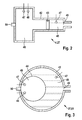
- the two pressure accumulators 27 as a high-pressure accumulator 28 and as a low-pressure accumulator 29 are, for example, as a piston accumulator 4 (FIG. Fig. 2 ) or a bladder memory 51 ( Fig. 3 ) educated.
- the piston accumulator 4 has a wall 42 made of steel and the wall 42 also forms a cylinder for supporting a piston 43.
- the piston 43 separates a trapped by the wall 42 total space as a total volume in a hydraulic fluid chamber 45, which is filled with hydraulic fluid and in a gas space 46, which only with gas, z. As air or nitrogen, is filled.
- a pressure sensor 47 detects a measuring pressure of the gas in the gas space 46
- a temperature sensor 48 detects a measuring temperature of the gas in the gas space 46.
- the pressure sensor 47 (shown in phantom) can also be arranged in the hydraulic fluid space 45, because the pressure of the Gas in the gas space 46 is identical to the pressure of the hydraulic fluid in the hydraulic fluid chamber 45.
- a filling valve 50 serves to fill and empty the gas space 46 with gas. During filling, the substance quantity n of the gas is detected as well as the molar gas constant R of the gas. Thus, in the operation of the piston accumulator 4, the amount of substance n is constant and thus both the amount of substance n and the molar gas constant R known, if no leakage occurs.
- a bladder memory 51 is shown.
- the hydraulic fluid space 45 is separated from the gas space 46 by a plastic elastic bladder 44.
- V n R T P
- the pressure sensor 47 detects the actual pressure as the measuring pressure with a first time delay of approximately 0.01 s, and the temperature sensor 48 detects the actual temperature as the measuring temperature with a second time delay of approximately 2 to 3 s.
- the second time delay of the temperature sensor 48 is thus substantially greater than the first time delay of the pressure sensor 47.
- C p is the specific heat capacity of the gas per molar mass
- T g is the temperature of the gas
- Q is the heat losses of the gas into the environment
- P is the pressure of the gas
- n is the number of moles of gas or the molar of the gas.
- T i is the temperature of the i-th surrounding element around the gas space 46 and K i is the thermal conductivity of the ith surrounding element.
- the first surrounding element, the wall 42 directly to the gas space 46 and the second surrounding element is the piston 43rd
- the temperature of the gas is also dependent on the temperature of the surrounding elements, so that the temperature of the surrounding elements would actually have to be iteratively approximated. This would require knowledge of the pressure accumulator 27 with respect to the geometrical parameters, for example the surface and the thermal properties of the surrounding elements, in order to be able to approximate the temperature of the surrounding elements sufficiently accurately iteratively.
- the present model calculation assumes a pressure sensor 27 with a short first time delay and a temperature sensor 48 with a large second time delay without the need for iterative approximation of the temperature of the surrounding elements.
- n is the mass of the gas and c is the specific heat capacity of the gas per unit mass.
- the pressure sensor 47 has, for example, a first time delay of 0.01 s, so that the pressure sensor 47 has a sampling frequency f of 100 Hz.
- the temperature sensor 48 has, for example, a second delay of 2 s, ie the temperature sensor 48 has a sampling frequency f of 0.5 Hz.
- Both the pressure sensor 47 and the temperature sensor 48 have a sampling frequency of at least 0.2 Hz, so that with the pressure sensor 47 and the temperature sensor 48, the change of the temperature T g of the gas in the accumulator 27 due to heat loss or heat gain by the surrounding elements or walls 42 can be detected.
- n C p d T G d t L F d Q d t L F + n R T G P ⁇ d P d t L F
- n C p d T G d t H F n R T G P ⁇ d P d t H F
- T g in the low-frequency component LF is the measured temperature T sensor detected by the temperature sensor .
- T G d t L F d T sensor d t
- the second summand K is a correction factor as a high-frequency filter for the measured pressure detected by the pressure sensor 47, and with the above differential equation the correction factor K is calculated, wherein in K the course of the measuring pressure is also dependent on the Time is taken into account.
- the measuring pressure of the pressure sensor 47 is multiplied by the calculated correction factor K and to this first summand, the measuring temperature of the temperature sensor 48 is added as the second summand, so that the sum of the first and second summands the current model temperature of the gas in the pressure accumulator 27 results.
- the correction factor or high-frequency filter transforms the measuring pressure of the pressure sensor 47 into a temperature value such that the actual temperature of the gas results from the sum of the first and second summands with a good approximation with a time delay which is essentially the first time Delay of the measuring pressure corresponds.
- the fast measured values of the pressure sensor 47 can thus be used to determine the model temperature together with the slow measuring temperature of the temperature sensor 48.
- V n R T P
- the model calculation carried out by the arithmetic unit 39 makes it possible to determine the actual temperature T g of the gas with a slight time delay with respect to the actual temperature of the gas, so that the disadvantage of the large second time delay of the temperature sensor 48 is essentially eliminated and thus the current volume of the gas and thus the state of charge of the pressure accumulator 27 can be determined with a high accuracy at the current time.
- the above calculations can be carried out with the equation of state of real gases instead of the equation of state of ideal gases.
- the equation of state for real gases additionally has the real gas factor Z.
- the drive train 1 has the high-pressure accumulator 28 and the low-pressure accumulator 29.
- the two pressure accumulators 27 are each formed with the gas space 46 and the hydraulic working chamber 45 and the gas space 46 is separated from the hydraulic working chamber 45 with a bladder 44 or a piston 43 as a movable separating element 43, 44, so that the high and low pressure accumulator 27, 28 , 29 are formed as bladder accumulator 51 or piston accumulator 4.
- At the high and / or low pressure accumulator 27, 28, 29 may leak or leakage occur, so that the amount or the mass of the gas in each of a high and / or low pressure accumulator 27, 28, 29 can shrink and / or it can reduce the amount of substance or the mass of the hydraulic fluid. Loss of gas and / or hydraulic fluid above critical levels may limit the operability of the powertrain 1.
- the actual variable volume V g -HP of the gas in the high-pressure accumulator 28 and the actual variable volume V g-LP of the gas in the low-pressure accumulator 29 can be calculated by the following equations.
- the actual specific volume V g -HP of the gas in the high-pressure accumulator 28 and the actual specific volume V g-LP of the gas in the low-pressure accumulator 29 can be given by appropriate calculations as volume per unit mass or volume per unit of mass.
- V G - HP + V G - LP V HP + V LP - V oil - HP + V oil - LP
- n g-HP the molar mass of the gas in the high pressure accumulator 28
- V g-LP is given as a function of V g-HP .
- v G - L P - n G - H P n G - L P v G - H P + V tank - V oil n G - L P
- a loss of gas in the low-pressure accumulator 29 changes the value of m and the value of d.
- a loss of gas in the high-pressure accumulator 28 changes the value of m but not the value of d.
- a loss of hydraulic fluid changes the value of d, but not the value of m.
- a simultaneous loss of gas and hydraulic fluid changes the value of m and d.
- the actual volume V g-HP of the high-pressure accumulator 28 and the current volume V g-LP of the low-pressure accumulator 29 can be more ideal or more real from the above calculation of the model temperature T or T g and the measuring pressure P of the pressure sensor 47 with the equation of state Gases are calculated.
- the values for m and d as test parameters for the leakage, in particular leakage quantity, of gas and / or hydraulic fluid can be calculated for each iteration step with the recursive least squares method.
- Permissible test parameter ranges for the test parameters m and d are stored in the arithmetic unit 39, and if the values for m and d deviate outside the permissible test parameter range, there is an intolerable leak or leakage at the high and / or low pressure accumulator 28, 29. It can then at least one damage measure, such as a fault message are issued and / or the operation with the hydraulic drive sub-strand 3 and / or the operation of the hydraulic drive sub-strand 3 to the losses, in particular the amount of losses, of gas and / or hydraulic fluid be adapted to be executed.
- the entire hydraulic fluid can also be pumped into the low-pressure accumulator 29 in a diagnostic step, so that in the high-pressure accumulator 28 the volume V g-HP of the gas corresponds to the total volume V HP of the high-pressure accumulator 28.
Landscapes
- Engineering & Computer Science (AREA)
- Mechanical Engineering (AREA)
- Chemical & Material Sciences (AREA)
- Combustion & Propulsion (AREA)
- Transportation (AREA)
- General Engineering & Computer Science (AREA)
- Supply Devices, Intensifiers, Converters, And Telemotors (AREA)
Applications Claiming Priority (1)
| Application Number | Priority Date | Filing Date | Title |
|---|---|---|---|
| DE102014222766.6A DE102014222766A1 (de) | 2014-11-07 | 2014-11-07 | Verfahren zur Steuerung und Regelung eines Antriebsstranges |
Publications (1)
| Publication Number | Publication Date |
|---|---|
| EP3021012A1 true EP3021012A1 (fr) | 2016-05-18 |
Family
ID=54360027
Family Applications (1)
| Application Number | Title | Priority Date | Filing Date |
|---|---|---|---|
| EP15190951.2A Withdrawn EP3021012A1 (fr) | 2014-11-07 | 2015-10-22 | Procede de commande et de reglage d'une chaine cinematique |
Country Status (2)
| Country | Link |
|---|---|
| EP (1) | EP3021012A1 (fr) |
| DE (1) | DE102014222766A1 (fr) |
Cited By (2)
| Publication number | Priority date | Publication date | Assignee | Title |
|---|---|---|---|---|
| WO2017209664A1 (fr) * | 2016-05-30 | 2017-12-07 | Volvo Construction Equipment Ab | Système de courant pour une machine de travail |
| CN110455531A (zh) * | 2019-08-14 | 2019-11-15 | 山东科技大学 | 一种功率分流式液压机械复合传动系统多功能测试试验台及其应用 |
Citations (7)
| Publication number | Priority date | Publication date | Assignee | Title |
|---|---|---|---|---|
| DE3609701A1 (de) * | 1986-03-20 | 1987-09-24 | Siemens Ag | Verfahren zur ueberwachung der gasmenge in einem hydropneumatischen druckspeicher und einrichtung zur ausuebung des verfahrens |
| DE2733870C2 (fr) | 1976-09-14 | 1989-07-20 | Abex Corp., New York, N.Y., Us | |
| DE19542427A1 (de) | 1995-11-14 | 1997-05-15 | Linde Ag | Hydrostatisches Antriebssystem für ein hydrostatisches betriebenes Fahrzeug |
| DE102009001357A1 (de) * | 2009-03-05 | 2010-09-09 | Robert Bosch Gmbh | Verfahren zum Betreiben eines Hydraulikhybridfahrzeugs |
| US20100313849A1 (en) * | 2009-06-11 | 2010-12-16 | Michael Anthony Stoner | Fault Detection and Mitigation in Hybrid Drive System |
| DE102012222717A1 (de) * | 2012-12-11 | 2014-06-12 | Robert Bosch Gmbh | Antriebsstrang |
| DE102013215862A1 (de) | 2013-08-12 | 2015-02-12 | Robert Bosch Gmbh | Verfahren zur Steuerung und Regelung eines Antriebsstranges |
-
2014
- 2014-11-07 DE DE102014222766.6A patent/DE102014222766A1/de not_active Withdrawn
-
2015
- 2015-10-22 EP EP15190951.2A patent/EP3021012A1/fr not_active Withdrawn
Patent Citations (7)
| Publication number | Priority date | Publication date | Assignee | Title |
|---|---|---|---|---|
| DE2733870C2 (fr) | 1976-09-14 | 1989-07-20 | Abex Corp., New York, N.Y., Us | |
| DE3609701A1 (de) * | 1986-03-20 | 1987-09-24 | Siemens Ag | Verfahren zur ueberwachung der gasmenge in einem hydropneumatischen druckspeicher und einrichtung zur ausuebung des verfahrens |
| DE19542427A1 (de) | 1995-11-14 | 1997-05-15 | Linde Ag | Hydrostatisches Antriebssystem für ein hydrostatisches betriebenes Fahrzeug |
| DE102009001357A1 (de) * | 2009-03-05 | 2010-09-09 | Robert Bosch Gmbh | Verfahren zum Betreiben eines Hydraulikhybridfahrzeugs |
| US20100313849A1 (en) * | 2009-06-11 | 2010-12-16 | Michael Anthony Stoner | Fault Detection and Mitigation in Hybrid Drive System |
| DE102012222717A1 (de) * | 2012-12-11 | 2014-06-12 | Robert Bosch Gmbh | Antriebsstrang |
| DE102013215862A1 (de) | 2013-08-12 | 2015-02-12 | Robert Bosch Gmbh | Verfahren zur Steuerung und Regelung eines Antriebsstranges |
Cited By (4)
| Publication number | Priority date | Publication date | Assignee | Title |
|---|---|---|---|---|
| WO2017209664A1 (fr) * | 2016-05-30 | 2017-12-07 | Volvo Construction Equipment Ab | Système de courant pour une machine de travail |
| US11186966B2 (en) | 2016-05-30 | 2021-11-30 | Volvo Construction Equipment Ab | Power system for a work machine |
| CN110455531A (zh) * | 2019-08-14 | 2019-11-15 | 山东科技大学 | 一种功率分流式液压机械复合传动系统多功能测试试验台及其应用 |
| CN110455531B (zh) * | 2019-08-14 | 2020-04-21 | 山东科技大学 | 一种液压机械复合传动系统试验台及其应用 |
Also Published As
| Publication number | Publication date |
|---|---|
| DE102014222766A1 (de) | 2016-05-12 |
Similar Documents
| Publication | Publication Date | Title |
|---|---|---|
| EP0252246B1 (fr) | Dispositif d'essay d'unités d'entraînement | |
| EP1210534B1 (fr) | Procede pour la regulation d'un embrayage ou d'un frein dans une transmission | |
| DE102012021211B4 (de) | Verfahren zum Ermitteln eines Einstellparameters in einer hydraulischen Aktuatoranordnung für einen Kraftfahrzeugantriebsstrang und Verfahren zum Betätigen einer Reibkupplung eines Kraftfahrzeugantriebsstranges | |
| DE69935033T2 (de) | Regelungsverfahren für die Pumpe eines frontgetriebenen Radfahrzeuges mit hydrostatischem Antrieb | |
| DE102015102283B4 (de) | Baugruppe eines stufenlosen Getriebes sowie damit ausgerüstetes Fahrzeug mit einer schlupfgesteuertenVariatorbaugruppe | |
| EP0859171B1 (fr) | Méthode de calibration des embrayages d'une transmission | |
| DE102010042528B4 (de) | Einrichtung und Verfahren zur Regelung einer mehrfachen Drehmomentbelastung einer Kupplung eines Kraftfahrzeugs auf einem Rollenprüfstand | |
| DE102010000781A1 (de) | Massemessung eines Schwungrad-Hybridfahrzeugs | |
| DE102013215862A1 (de) | Verfahren zur Steuerung und Regelung eines Antriebsstranges | |
| EP0931961B1 (fr) | Procédé de calibration d'étalonnage pour commande d'embrayage de transmissions | |
| EP3021012A1 (fr) | Procede de commande et de reglage d'une chaine cinematique | |
| DE102016120916B4 (de) | Verfahren zur Steuerung eines stufenlosen Getriebes und zugehöriges Getriebe | |
| WO2022007992A1 (fr) | Procédé pour commander un décalage de chevauchement d'un double embrayage à actionnement hydraulique | |
| WO2016078702A1 (fr) | Procédé de régulation d'une pression réelle d'un embrayage d'un véhicule automobile | |
| DE102012218973A1 (de) | Verfahren zum Bestimmen einer Betätigungszeit einer Kupplungsanordnung eines Leistungsverzweigungsgetriebes mit Variator | |
| DE102014212156A1 (de) | Verfahren zur Steuerung und Regelung eines Antriebsstranges | |
| DE102015213838A1 (de) | Verfahren zur Steuerung und Regelung eines Antriebsstranges | |
| DE102016216136A1 (de) | Verfahren zur Einstellung eines Volumenstroms oder eines geförderten Volumens einer hydraulischen Aktoranordnung | |
| DE102014222765A1 (de) | Verfahren zur Steuerung und Regelung eines Antriebsstranges | |
| DE102014225363A1 (de) | Verfahren zur Steuerung und Regelung eines Antriebsstranges | |
| DE102014225243A1 (de) | Verfahren zur Steuerung und Regelung eines Antriebsstranges | |
| DE102014212182A1 (de) | Verfahren zur Steuerung und Regelung eines Antriebsstranges | |
| DE102011082673A1 (de) | Getriebevorrichtung mit wenigstens einem Variator zum stufenlosen Variieren einer Übersetzung | |
| DE102012202295B4 (de) | Verfahren zum Einstellen von Applikationsdaten eines Steuergeräts | |
| DE102019215033A1 (de) | Verfahren zum Betreiben einer Getriebebremse |
Legal Events
| Date | Code | Title | Description |
|---|---|---|---|
| PUAI | Public reference made under article 153(3) epc to a published international application that has entered the european phase |
Free format text: ORIGINAL CODE: 0009012 |
|
| AK | Designated contracting states |
Kind code of ref document: A1 Designated state(s): AL AT BE BG CH CY CZ DE DK EE ES FI FR GB GR HR HU IE IS IT LI LT LU LV MC MK MT NL NO PL PT RO RS SE SI SK SM TR |
|
| AX | Request for extension of the european patent |
Extension state: BA ME |
|
| STAA | Information on the status of an ep patent application or granted ep patent |
Free format text: STATUS: THE APPLICATION IS DEEMED TO BE WITHDRAWN |
|
| 18D | Application deemed to be withdrawn |
Effective date: 20161119 |