EP3021058A1 - Système de réfrigération de dioxyde de carbone transcritique avec plusieurs éjecteurs - Google Patents
Système de réfrigération de dioxyde de carbone transcritique avec plusieurs éjecteurs Download PDFInfo
- Publication number
- EP3021058A1 EP3021058A1 EP15195039.1A EP15195039A EP3021058A1 EP 3021058 A1 EP3021058 A1 EP 3021058A1 EP 15195039 A EP15195039 A EP 15195039A EP 3021058 A1 EP3021058 A1 EP 3021058A1
- Authority
- EP
- European Patent Office
- Prior art keywords
- carbon dioxide
- low temperature
- mid
- refrigeration system
- ejector
- Prior art date
- Legal status (The legal status is an assumption and is not a legal conclusion. Google has not performed a legal analysis and makes no representation as to the accuracy of the status listed.)
- Withdrawn
Links
Images



Classifications
-
- F—MECHANICAL ENGINEERING; LIGHTING; HEATING; WEAPONS; BLASTING
- F25—REFRIGERATION OR COOLING; COMBINED HEATING AND REFRIGERATION SYSTEMS; HEAT PUMP SYSTEMS; MANUFACTURE OR STORAGE OF ICE; LIQUEFACTION SOLIDIFICATION OF GASES
- F25D—REFRIGERATORS; COLD ROOMS; ICE-BOXES; COOLING OR FREEZING APPARATUS NOT OTHERWISE PROVIDED FOR
- F25D3/00—Devices using other cold materials; Devices using cold-storage bodies
- F25D3/12—Devices using other cold materials; Devices using cold-storage bodies using solidified gases, e.g. carbon-dioxide snow
-
- F—MECHANICAL ENGINEERING; LIGHTING; HEATING; WEAPONS; BLASTING
- F25—REFRIGERATION OR COOLING; COMBINED HEATING AND REFRIGERATION SYSTEMS; HEAT PUMP SYSTEMS; MANUFACTURE OR STORAGE OF ICE; LIQUEFACTION SOLIDIFICATION OF GASES
- F25B—REFRIGERATION MACHINES, PLANTS OR SYSTEMS; COMBINED HEATING AND REFRIGERATION SYSTEMS; HEAT PUMP SYSTEMS
- F25B1/00—Compression machines, plants or systems with non-reversible cycle
- F25B1/10—Compression machines, plants or systems with non-reversible cycle with multi-stage compression
-
- F—MECHANICAL ENGINEERING; LIGHTING; HEATING; WEAPONS; BLASTING
- F25—REFRIGERATION OR COOLING; COMBINED HEATING AND REFRIGERATION SYSTEMS; HEAT PUMP SYSTEMS; MANUFACTURE OR STORAGE OF ICE; LIQUEFACTION SOLIDIFICATION OF GASES
- F25B—REFRIGERATION MACHINES, PLANTS OR SYSTEMS; COMBINED HEATING AND REFRIGERATION SYSTEMS; HEAT PUMP SYSTEMS
- F25B41/00—Fluid-circulation arrangements
-
- F—MECHANICAL ENGINEERING; LIGHTING; HEATING; WEAPONS; BLASTING
- F25—REFRIGERATION OR COOLING; COMBINED HEATING AND REFRIGERATION SYSTEMS; HEAT PUMP SYSTEMS; MANUFACTURE OR STORAGE OF ICE; LIQUEFACTION SOLIDIFICATION OF GASES
- F25B—REFRIGERATION MACHINES, PLANTS OR SYSTEMS; COMBINED HEATING AND REFRIGERATION SYSTEMS; HEAT PUMP SYSTEMS
- F25B5/00—Compression machines, plants or systems, with several evaporator circuits, e.g. for varying refrigerating capacity
-
- F—MECHANICAL ENGINEERING; LIGHTING; HEATING; WEAPONS; BLASTING
- F25—REFRIGERATION OR COOLING; COMBINED HEATING AND REFRIGERATION SYSTEMS; HEAT PUMP SYSTEMS; MANUFACTURE OR STORAGE OF ICE; LIQUEFACTION SOLIDIFICATION OF GASES
- F25B—REFRIGERATION MACHINES, PLANTS OR SYSTEMS; COMBINED HEATING AND REFRIGERATION SYSTEMS; HEAT PUMP SYSTEMS
- F25B9/00—Compression machines, plants or systems, in which the refrigerant is air or other gas of low boiling point
- F25B9/002—Compression machines, plants or systems, in which the refrigerant is air or other gas of low boiling point characterised by the refrigerant
- F25B9/008—Compression machines, plants or systems, in which the refrigerant is air or other gas of low boiling point characterised by the refrigerant the refrigerant being carbon dioxide
-
- F—MECHANICAL ENGINEERING; LIGHTING; HEATING; WEAPONS; BLASTING
- F25—REFRIGERATION OR COOLING; COMBINED HEATING AND REFRIGERATION SYSTEMS; HEAT PUMP SYSTEMS; MANUFACTURE OR STORAGE OF ICE; LIQUEFACTION SOLIDIFICATION OF GASES
- F25B—REFRIGERATION MACHINES, PLANTS OR SYSTEMS; COMBINED HEATING AND REFRIGERATION SYSTEMS; HEAT PUMP SYSTEMS
- F25B2309/00—Gas cycle refrigeration machines
- F25B2309/06—Compression machines, plants or systems characterised by the refrigerant being carbon dioxide
- F25B2309/061—Compression machines, plants or systems characterised by the refrigerant being carbon dioxide with cycle highest pressure above the supercritical pressure
-
- F—MECHANICAL ENGINEERING; LIGHTING; HEATING; WEAPONS; BLASTING
- F25—REFRIGERATION OR COOLING; COMBINED HEATING AND REFRIGERATION SYSTEMS; HEAT PUMP SYSTEMS; MANUFACTURE OR STORAGE OF ICE; LIQUEFACTION SOLIDIFICATION OF GASES
- F25B—REFRIGERATION MACHINES, PLANTS OR SYSTEMS; COMBINED HEATING AND REFRIGERATION SYSTEMS; HEAT PUMP SYSTEMS
- F25B2341/00—Details of ejectors not being used as compression device; Details of flow restrictors or expansion valves
- F25B2341/001—Ejectors not being used as compression device
- F25B2341/0012—Ejectors with the cooled primary flow at high pressure
-
- F—MECHANICAL ENGINEERING; LIGHTING; HEATING; WEAPONS; BLASTING
- F25—REFRIGERATION OR COOLING; COMBINED HEATING AND REFRIGERATION SYSTEMS; HEAT PUMP SYSTEMS; MANUFACTURE OR STORAGE OF ICE; LIQUEFACTION SOLIDIFICATION OF GASES
- F25B—REFRIGERATION MACHINES, PLANTS OR SYSTEMS; COMBINED HEATING AND REFRIGERATION SYSTEMS; HEAT PUMP SYSTEMS
- F25B2341/00—Details of ejectors not being used as compression device; Details of flow restrictors or expansion valves
- F25B2341/001—Ejectors not being used as compression device
- F25B2341/0015—Ejectors not being used as compression device using two or more ejectors
-
- F—MECHANICAL ENGINEERING; LIGHTING; HEATING; WEAPONS; BLASTING
- F25—REFRIGERATION OR COOLING; COMBINED HEATING AND REFRIGERATION SYSTEMS; HEAT PUMP SYSTEMS; MANUFACTURE OR STORAGE OF ICE; LIQUEFACTION SOLIDIFICATION OF GASES
- F25B—REFRIGERATION MACHINES, PLANTS OR SYSTEMS; COMBINED HEATING AND REFRIGERATION SYSTEMS; HEAT PUMP SYSTEMS
- F25B2400/00—Component parts or details not otherwise provided for in this subclass
- F25B2400/05—Compression system with heat exchange between particular parts of the system
- F25B2400/054—Compression system with heat exchange between particular parts of the system between the suction tube of the compressor and another part of the cycle
-
- F—MECHANICAL ENGINEERING; LIGHTING; HEATING; WEAPONS; BLASTING
- F25—REFRIGERATION OR COOLING; COMBINED HEATING AND REFRIGERATION SYSTEMS; HEAT PUMP SYSTEMS; MANUFACTURE OR STORAGE OF ICE; LIQUEFACTION SOLIDIFICATION OF GASES
- F25B—REFRIGERATION MACHINES, PLANTS OR SYSTEMS; COMBINED HEATING AND REFRIGERATION SYSTEMS; HEAT PUMP SYSTEMS
- F25B2400/00—Component parts or details not otherwise provided for in this subclass
- F25B2400/07—Details of compressors or related parts
- F25B2400/072—Intercoolers therefor
-
- F—MECHANICAL ENGINEERING; LIGHTING; HEATING; WEAPONS; BLASTING
- F25—REFRIGERATION OR COOLING; COMBINED HEATING AND REFRIGERATION SYSTEMS; HEAT PUMP SYSTEMS; MANUFACTURE OR STORAGE OF ICE; LIQUEFACTION SOLIDIFICATION OF GASES
- F25B—REFRIGERATION MACHINES, PLANTS OR SYSTEMS; COMBINED HEATING AND REFRIGERATION SYSTEMS; HEAT PUMP SYSTEMS
- F25B2400/00—Component parts or details not otherwise provided for in this subclass
- F25B2400/07—Details of compressors or related parts
- F25B2400/075—Details of compressors or related parts with parallel compressors
Definitions
- the present application and the resultant patent relate generally to refrigeration systems and more particularly relate to a transcritical carbon dioxide refrigeration system using multiple ejectors at multiple temperatures for improved overall efficiency.
- the present application and the resultant patent thus provide a carbon dioxide based refrigeration system.
- the carbon dioxide based refrigeration system may include a mid temperature cycle with a mid temperature ejector, a low temperature cycle with a low temperature ejector, and a gas cooler/condenser in communication with the mid temperature cycle and the low temperature cycle.
- the present application and the resultant patent further provide a method of operating a carbon dioxide based refrigeration system.
- the method may include the steps of flowing a first portion of a carbon dioxide refrigerant to a mid temperature ejector, accelerating the first portion of the flow of the carbon dioxide refrigerant in the mid temperature ejector, flowing the first portion of the flow of the carbon dioxide refrigerant to a mid temperature suction group, flowing a second portion of the carbon dioxide refrigerant to a low temperature ejector, accelerating the second portion of the flow of the carbon dioxide refrigerant in the low temperature ejector, and flowing the second portion of the flow of the carbon dioxide refrigerant to a low temperature suction group.
- the present application and the resultant patent further provide a refrigeration system.
- the refrigeration system may include a flow of a carbon dioxide refrigerant, a mid temperature cycle with a mid temperature ejector, a low temperature cycle with a low temperature ejector and a gas cooler/condenser in communication with the mid temperature cycle, and the low temperature cycle.
- a first portion of the flow of the carbon dioxide refrigerant flows through the mid temperature cycle and a second portion of the flow of the carbon dioxide refrigerant flows through the low temperature cycle.
- Fig. 1 shows an example of an ejector 100 as may be described herein.
- the ejector 100 may be a mechanical device with or without any moving parts. Instead, the ejector 100 mixes two fluid streams based upon a momentum transfer between a motive fluid and a suction fluid.
- a motive inlet 110 may be in communication with a first flow under pressure.
- the ejector 100 also may include a suction inlet 120 in communication with a second flow.
- the ejector 100 also may include a mixing tube 130 and a diffuser 140.
- the motive flow may be reduced in pressure as the suction flow is accelerated therein.
- the flows are mixed in the mixing tube 130 and flow through the diffuser 140 as a mixed flow.
- the mixed flow may be discharged at an outlet 150 at a pressure greater than the suction flow but less than the motive flow.
- the overall suction capability for the ejector 100 may be based upon the net positive suction head available therein. Other component and other configurations also may be used herein.
- Fig. 2 shows an example of a carbon dioxide based refrigeration system 160 as may be described herein.
- the transcritical carbon dioxide based refrigeration system 160 may include a number of the ejectors 100 in a parallel configuration 170.
- a medium temperature ejector 180 may be used in a medium temperature cycle 190 and a low temperature ejector 200 may be used in a low temperature cycle 210.
- Other components and other configurations also may be used herein.
- the mid temperature cycle 190 and the low temperature cycle 210 operate at different temperatures.
- the mid temperature cycle 190 may include any number of mid temperature suction groups 220 or compressors.
- the mid temperature suction groups 220 may be used herein in a parallel configuration or otherwise.
- the mid temperature suction groups 220 compress a flow of a carbon dioxide refrigerant 230.
- Other types of refrigerant flows may be used herein.
- the carbon dioxide refrigerant 230 may be forwarded to a gas cooler/condenser 240.
- the carbon dioxide refrigerant 230 may lose or reject heat in the gas cooler/condenser.
- the mid temperature cycle 190 also may include a mid temperature suction line heat exchanger 250.
- the mid temperature suction line heat exchanger 250 may exchange heat between the flow of refrigerant 230 entering the mid temperature suction groups 220 and the flow of refrigerant 230 leaving the gas cooler/condenser 240.
- Other components and other configurations also may be used herein.
- a first portion 260 of the flow of refrigerant 230 leaving the gas cooler/condenser 240 may be directed to the mid temperature ejector 180.
- the first portion 260 of the refrigerant flow 230 may be substantially gaseous.
- the mid temperature ejector 180 also may be in communication with a mid temperature flash tank 270 and one or more mid temperature evaporators 280.
- the mid temperature evaporators 280 may be evenly or unevenly sized to cover a certain capacity range and modulation.
- the first portion 260 of the flow 230 may enter the mid temperature ejector 180 at the motive inlet 110 as the motive flow.
- the flow of refrigerant 230 from the mid temperature evaporators 280 may enter the suction inlet 120 in a liquid state as the suction flow.
- the motive flow of refrigerant 230 thus may be accelerated and reduced in pressure upon leaving the outlet 150.
- the flow of refrigerant 230 then may again be separated into vapor and liquid form in the temperature flash tank 270.
- the vaporized refrigerant 230 may be returned to the mid temperature suction groups 220 via the mid temperature suction line heat exchanger 250 while the liquid flow may be sent to the mid temperature evaporators 280 and back to the mid temperature ejector 180.
- Other components and other configurations also may be used herein.
- a second portion 290 of the flow of refrigerant 230 from the gas cooler/condenser 240 may be routed to the low temperature ejector 200 of the low temperature cycle 210.
- the second portion 290 of the flow of refrigerant 230 may first pass through a low temperature suction line heat exchanger 300.
- the low temperature ejector 200 also may be in communication with a low temperature flash tank 310 and one or more low temperature evaporators 320.
- the low temperature evaporators 320 may be evenly or unevenly sized to cover a certain capacity range and modulation.
- the second portion 290 of the flow of refrigerant 230 thus may enter the motive inlet 110 of the low temperature ejector 200 while the flow of refrigerant 230 from the low temperature evaporator 320 may enter at the suction inlet 120. Again the mixed flow may be accelerated and reduced in pressure. The mixed flow thus leaves the outlet 150 of the low temperature ejector 200 and flows to the low temperature flash tank 310.
- the vaporized portion of the flow of refrigerant 230 may flow through the low temperature suction line heat exchanger 300 and towards a number of low temperature suction groups 330 or compressors.
- the flow of refrigerant 230 then may be forwarded to the mid temperature flash tank 270 or directly back to the gas cooler/condenser 240.
- the liquid portion of the flow of refrigerant 230 may pass through the low temperature evaporator 320 and back to the low temperature ejector 200. The cycle then may be repeated.
- the use of the ejectors 180, 200 serves to recover pressure/work herein.
- the work recovered from the expansion process may be used to compress the vaporized refrigerant before entering into the compressors/suction groups. Accordingly, the pressure ratio of the suction groups (and thus the overall power consumption) may be reduced for a given evaporator pressure.
- the quality of the refrigerant also may be reduced.
- the overall number of pumps also may be reduced and/or eliminated.
- Fig. 3 shows an alternative embodiment of a carbon dioxide refrigeration system 160.
- the ejectors 100 may be positioned in a series configuration.
- a medium temperature cycle 350 and a low temperature cycle 360 may be positioned in a series configuration.
- Other components and other configurations may be used herein.
- the mid temperature cycle 350 may include the mid temperature suction groups 220, the gas cooler/condenser 240, and the mid temperature suction line heat exchanger 250 substantially as described above. In this example, however, the entire flow of refrigerant 230 may be directed to the mid temperature ejector 180.
- the mid temperature ejector 180 also may be in communication with the mid temperature flash tank 270 and the mid temperature evaporator 280.
- a first portion 370 of the fluid refrigerant 230 may be directed to the mid temperature evaporators 280 while a second portion 380 may be forwarded to the low temperature cycle 360.
- the lower temperature cycle 360 also may include the low temperature suction line heat exchanger 300 and the low temperature ejector 200 in communication with the low temperature flash tank 310 and the low temperature evaporator 320.
- the low temperature cycle 360 also includes the low temperature suction groups 330. The flow of refrigerant 230 thus flows first through the mid temperature cycle 350 and then through the low temperature cycle 360 before being returned to either the mid temperature flash tank 270 and/or the gas cooler/condenser 240.
- Other components and other configurations may be used herein.
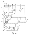
- Fig. 4 shows an alternative embodiment of Fig. 2 .
- an evaporator 390 or an assembly of evaporators 390 in a parallel configuration are positioned between the outlet of the low temperature ejector 200 and the inlet of the low temperature flash tank 310. Further, the flash tank liquid outlet is fed into the ejector suction port 120 in the low temperature cycle 210.
- This alternative embodiment enables overfeeding of the evaporator coils with liquid such that they can have heat transfer performance enhancement.
- Fig. 5 shows an alternative embodiment of the transcritical carbon dioxide based refrigeration system 160 of Fig. 3 .
- an evaporator 400 or an assembly of evaporators 400 in a parallel configuration are positioned in between the outlet of the low temperature ejector 200 and the inlet of the low temperature flash tank 310. Further, the flash tank liquid outlet is fed into the ejector suction port 120 in the low temperature cycle 360.
- This alternative embodiment also enables overfeeding of the evaporator coils with liquid such that they can have heat transfer performance enhancement.
Landscapes
- Engineering & Computer Science (AREA)
- Physics & Mathematics (AREA)
- Mechanical Engineering (AREA)
- Thermal Sciences (AREA)
- General Engineering & Computer Science (AREA)
- Chemical & Material Sciences (AREA)
- Chemical Kinetics & Catalysis (AREA)
- Combustion & Propulsion (AREA)
- Jet Pumps And Other Pumps (AREA)
- Filling Or Discharging Of Gas Storage Vessels (AREA)
- Organic Low-Molecular-Weight Compounds And Preparation Thereof (AREA)
Applications Claiming Priority (1)
| Application Number | Priority Date | Filing Date | Title |
|---|---|---|---|
| US14/542,704 US9897363B2 (en) | 2014-11-17 | 2014-11-17 | Transcritical carbon dioxide refrigeration system with multiple ejectors |
Publications (1)
| Publication Number | Publication Date |
|---|---|
| EP3021058A1 true EP3021058A1 (fr) | 2016-05-18 |
Family
ID=54705376
Family Applications (1)
| Application Number | Title | Priority Date | Filing Date |
|---|---|---|---|
| EP15195039.1A Withdrawn EP3021058A1 (fr) | 2014-11-17 | 2015-11-17 | Système de réfrigération de dioxyde de carbone transcritique avec plusieurs éjecteurs |
Country Status (6)
| Country | Link |
|---|---|
| US (1) | US9897363B2 (fr) |
| EP (1) | EP3021058A1 (fr) |
| AU (1) | AU2015249198A1 (fr) |
| BR (1) | BR102015028606A2 (fr) |
| CA (1) | CA2908431C (fr) |
| MX (1) | MX370520B (fr) |
Cited By (3)
| Publication number | Priority date | Publication date | Assignee | Title |
|---|---|---|---|---|
| DE102017124385A1 (de) | 2017-10-19 | 2019-04-25 | Technische Universität Dresden | Kälteanlage und Verfahren zum Betreiben der Kälteanlage |
| EP3584513A1 (fr) * | 2018-06-06 | 2019-12-25 | Heatcraft Refrigeration Products LLC | Système de refroidissement |
| US11754320B2 (en) | 2020-02-10 | 2023-09-12 | Carrier Corporation | Refrigeration system with multiple heat absorbing heat exchangers |
Families Citing this family (13)
| Publication number | Priority date | Publication date | Assignee | Title |
|---|---|---|---|---|
| WO2016180481A1 (fr) * | 2015-05-12 | 2016-11-17 | Carrier Corporation | Circuit de réfrigération d'éjecteur |
| PL3295093T3 (pl) * | 2015-05-12 | 2023-05-22 | Carrier Corporation | Obieg chłodniczy eżektora i sposób działania takiego obiegu |
| WO2017167374A1 (fr) * | 2016-03-31 | 2017-10-05 | Carrier Corporation | Circuit de réfrigération |
| US10352604B2 (en) * | 2016-12-06 | 2019-07-16 | Heatcraft Refrigeration Products Llc | System for controlling a refrigeration system with a parallel compressor |
| US10808966B2 (en) * | 2017-03-02 | 2020-10-20 | Heatcraft Refrigeration Products Llc | Cooling system with parallel compression |
| WO2018204184A1 (fr) * | 2017-05-02 | 2018-11-08 | Rolls-Royce North American Technologies Inc. | Procédé et appareil de refroidissement isotherme |
| CN109682102A (zh) * | 2019-01-28 | 2019-04-26 | 天津商业大学 | 带喷射引射的直接接触冷凝低温制冷系统 |
| CN109869940B (zh) * | 2019-03-26 | 2024-07-23 | 天津商业大学 | 喷射式跨临界二氧化碳双级压缩制冷系统 |
| CN110966802A (zh) * | 2019-12-25 | 2020-04-07 | 天津商业大学 | 一种带引射器的水蒸气热泵系统 |
| EP4027075B1 (fr) | 2021-01-06 | 2023-10-11 | Carrier Corporation | Système de réfrigération de dioxyde de carbone comprenant un mode basse température |
| CN114941915B (zh) * | 2022-05-18 | 2025-01-14 | 冰山冷热科技股份有限公司 | Co2亚/跨转换多工况综合应用制冷系统 |
| US12578131B2 (en) | 2023-11-10 | 2026-03-17 | Hamilton Sundstrand Corporation | Compressor oil recovery in hybrid VCC pumped two phase loops |
| US12552541B2 (en) * | 2023-11-10 | 2026-02-17 | Hamilton Sundstrand Corporation | Thermal management system for future vertical lift aircraft |
Citations (6)
| Publication number | Priority date | Publication date | Assignee | Title |
|---|---|---|---|---|
| US20100313582A1 (en) * | 2009-06-10 | 2010-12-16 | Oh Jongsik | High efficiency r744 refrigeration system and cycle |
| CH703290A1 (de) * | 2010-09-29 | 2011-12-15 | Erik Vincent Granwehr | Wärmepumpe. |
| WO2012012488A1 (fr) * | 2010-07-23 | 2012-01-26 | Carrier Corporation | Cycle d'éjection à haut rendement |
| WO2012012493A2 (fr) * | 2010-07-23 | 2012-01-26 | Carrier Corporation | Cycle d'éjection |
| WO2012012485A1 (fr) * | 2010-07-23 | 2012-01-26 | Carrier Corporation | Cycle frigorifique à éjecteur et dispositif frigorifique l'utilisant |
| EP2770276A1 (fr) * | 2011-09-30 | 2014-08-27 | Daikin Industries, Ltd. | Pompe à chaleur |
Family Cites Families (8)
| Publication number | Priority date | Publication date | Assignee | Title |
|---|---|---|---|---|
| JP2001221517A (ja) | 2000-02-10 | 2001-08-17 | Sharp Corp | 超臨界冷凍サイクル |
| JP2004198002A (ja) | 2002-12-17 | 2004-07-15 | Denso Corp | 蒸気圧縮式冷凍機 |
| CN1291196C (zh) | 2004-02-18 | 2006-12-20 | 株式会社电装 | 具有多蒸发器的喷射循环 |
| DE102006024211A1 (de) | 2005-05-24 | 2007-01-25 | Denso Corp., Kariya | Ejektorpumpe und Ejektorpumpenkreisvorrichtung |
| DK2718642T3 (en) | 2011-06-06 | 2016-12-19 | Huurre Group Oy | Multi-evaporator cooling circuits |
| JP5482767B2 (ja) * | 2011-11-17 | 2014-05-07 | 株式会社デンソー | エジェクタ式冷凍サイクル |
| ES2988494T3 (es) * | 2013-05-03 | 2024-11-20 | Hill Phoenix Inc | Sistemas y métodos para el control de presión en un sistema de refrigeración por CO2 |
| US9657969B2 (en) * | 2013-12-30 | 2017-05-23 | Rolls-Royce Corporation | Multi-evaporator trans-critical cooling systems |
-
2014
- 2014-11-17 US US14/542,704 patent/US9897363B2/en not_active Expired - Fee Related
-
2015
- 2015-10-07 CA CA2908431A patent/CA2908431C/fr active Active
- 2015-10-30 AU AU2015249198A patent/AU2015249198A1/en not_active Abandoned
- 2015-11-11 MX MX2015015611A patent/MX370520B/es active IP Right Grant
- 2015-11-13 BR BR102015028606-6A patent/BR102015028606A2/pt not_active Application Discontinuation
- 2015-11-17 EP EP15195039.1A patent/EP3021058A1/fr not_active Withdrawn
Patent Citations (6)
| Publication number | Priority date | Publication date | Assignee | Title |
|---|---|---|---|---|
| US20100313582A1 (en) * | 2009-06-10 | 2010-12-16 | Oh Jongsik | High efficiency r744 refrigeration system and cycle |
| WO2012012488A1 (fr) * | 2010-07-23 | 2012-01-26 | Carrier Corporation | Cycle d'éjection à haut rendement |
| WO2012012493A2 (fr) * | 2010-07-23 | 2012-01-26 | Carrier Corporation | Cycle d'éjection |
| WO2012012485A1 (fr) * | 2010-07-23 | 2012-01-26 | Carrier Corporation | Cycle frigorifique à éjecteur et dispositif frigorifique l'utilisant |
| CH703290A1 (de) * | 2010-09-29 | 2011-12-15 | Erik Vincent Granwehr | Wärmepumpe. |
| EP2770276A1 (fr) * | 2011-09-30 | 2014-08-27 | Daikin Industries, Ltd. | Pompe à chaleur |
Cited By (4)
| Publication number | Priority date | Publication date | Assignee | Title |
|---|---|---|---|---|
| DE102017124385A1 (de) | 2017-10-19 | 2019-04-25 | Technische Universität Dresden | Kälteanlage und Verfahren zum Betreiben der Kälteanlage |
| EP3584513A1 (fr) * | 2018-06-06 | 2019-12-25 | Heatcraft Refrigeration Products LLC | Système de refroidissement |
| US10808975B2 (en) | 2018-06-06 | 2020-10-20 | Heatcraft Refrigeration Products Llc | Cooling system |
| US11754320B2 (en) | 2020-02-10 | 2023-09-12 | Carrier Corporation | Refrigeration system with multiple heat absorbing heat exchangers |
Also Published As
| Publication number | Publication date |
|---|---|
| US9897363B2 (en) | 2018-02-20 |
| CA2908431A1 (fr) | 2016-05-17 |
| MX370520B (es) | 2019-12-17 |
| BR102015028606A2 (pt) | 2017-07-18 |
| CA2908431C (fr) | 2021-05-18 |
| MX2015015611A (es) | 2016-06-15 |
| US20160138847A1 (en) | 2016-05-19 |
| AU2015249198A1 (en) | 2016-06-02 |
Similar Documents
| Publication | Publication Date | Title |
|---|---|---|
| US9897363B2 (en) | Transcritical carbon dioxide refrigeration system with multiple ejectors | |
| US10612821B1 (en) | Heat-pump system with combined vapor expansion-compression stages and single-effect vapor absorption unit | |
| Sarkar | Review on Cycle Modifications of Transcritical CO 2 Refrigeration and Heat Pump Systems. | |
| US20130104593A1 (en) | Mass flow multiplier refrigeration cycle | |
| CN111174453B (zh) | 制冷系统 | |
| CN110486942A (zh) | 多级压缩多级冷凝中间闪蒸不完全冷却中高温热泵系统 | |
| CN108253651A (zh) | 一种带喷射器的双蒸发温度制冷系统 | |
| JP2012013412A (ja) | 冷凍サイクル装置 | |
| CN108800678A (zh) | 空调系统 | |
| CN108700354B (zh) | 冷凝器及具备该冷凝器的涡轮制冷装置 | |
| CN102494426B (zh) | 带回热式多元混合工质节流制冷的温度试验箱 | |
| CN104236159A (zh) | 一种多能源驱动制冷系统及制冷方法 | |
| KR20220035172A (ko) | 다중 압축기를 구비한 칠러 시스템 | |
| EP3106783A1 (fr) | Appareil d'échange de chaleur et appareil de pompe à chaleur | |
| KR102618118B1 (ko) | 냉동시스템의 냉매를 증압 순환시키는 냉매액 펌프의 흡입측에 낮은 온도의 냉매를 공급 순환시키기 위한 액상냉매 순환방법 | |
| JP2015102319A (ja) | 冷凍サイクル装置 | |
| CN114370715B (zh) | 一种双级自复叠制冷系统 | |
| CN209355524U (zh) | 一种冷热能量利用系统 | |
| CN110486943A (zh) | 多级压缩多冷凝器中间节流不完全冷却中高温热泵系统 | |
| CN102878715B (zh) | 一种射流泵节流供液制冷系统 | |
| AU2024201902B2 (en) | Oil management system for multiple compressors | |
| CN211119988U (zh) | 多级压缩多级冷凝中间闪蒸不完全冷却中高温热泵系统 | |
| CN103954069A (zh) | 一种多热源喷射式制冷机 | |
| US20080184722A1 (en) | Method and apparatus for a refrigeration circuit | |
| WO2020113332A1 (fr) | Système et procédé de réfrigération par compression mécanique basée sur un éjecteur à deux phases |
Legal Events
| Date | Code | Title | Description |
|---|---|---|---|
| PUAI | Public reference made under article 153(3) epc to a published international application that has entered the european phase |
Free format text: ORIGINAL CODE: 0009012 |
|
| AK | Designated contracting states |
Kind code of ref document: A1 Designated state(s): AL AT BE BG CH CY CZ DE DK EE ES FI FR GB GR HR HU IE IS IT LI LT LU LV MC MK MT NL NO PL PT RO RS SE SI SK SM TR |
|
| AX | Request for extension of the european patent |
Extension state: BA ME |
|
| STAA | Information on the status of an ep patent application or granted ep patent |
Free format text: STATUS: REQUEST FOR EXAMINATION WAS MADE |
|
| 17P | Request for examination filed |
Effective date: 20161117 |
|
| RBV | Designated contracting states (corrected) |
Designated state(s): AL AT BE BG CH CY CZ DE DK EE ES FI FR GB GR HR HU IE IS IT LI LT LU LV MC MK MT NL NO PL PT RO RS SE SI SK SM TR |
|
| STAA | Information on the status of an ep patent application or granted ep patent |
Free format text: STATUS: EXAMINATION IS IN PROGRESS |
|
| 17Q | First examination report despatched |
Effective date: 20190524 |
|
| STAA | Information on the status of an ep patent application or granted ep patent |
Free format text: STATUS: THE APPLICATION IS DEEMED TO BE WITHDRAWN |
|
| 18D | Application deemed to be withdrawn |
Effective date: 20220301 |