EP3021095A1 - Système de spectroscopie avec compensation de déplacement et procédé de spectroscopie utilisant ledit système - Google Patents
Système de spectroscopie avec compensation de déplacement et procédé de spectroscopie utilisant ledit système Download PDFInfo
- Publication number
- EP3021095A1 EP3021095A1 EP15193113.6A EP15193113A EP3021095A1 EP 3021095 A1 EP3021095 A1 EP 3021095A1 EP 15193113 A EP15193113 A EP 15193113A EP 3021095 A1 EP3021095 A1 EP 3021095A1
- Authority
- EP
- European Patent Office
- Prior art keywords
- detection
- detection areas
- spectroscopy
- target area
- spectrums
- Prior art date
- Legal status (The legal status is an assumption and is not a legal conclusion. Google has not performed a legal analysis and makes no representation as to the accuracy of the status listed.)
- Granted
Links
Images



Classifications
-
- G—PHYSICS
- G01—MEASURING; TESTING
- G01J—MEASUREMENT OF INTENSITY, VELOCITY, SPECTRAL CONTENT, POLARISATION, PHASE OR PULSE CHARACTERISTICS OF INFRARED, VISIBLE OR ULTRAVIOLET LIGHT; COLORIMETRY; RADIATION PYROMETRY
- G01J3/00—Spectrometry; Spectrophotometry; Monochromators; Measuring colours
- G01J3/02—Details
- G01J3/0289—Field-of-view determination; Aiming or pointing of a spectrometer; Adjusting alignment; Encoding angular position; Size of measurement area; Position tracking
-
- A—HUMAN NECESSITIES
- A61—MEDICAL OR VETERINARY SCIENCE; HYGIENE
- A61B—DIAGNOSIS; SURGERY; IDENTIFICATION
- A61B5/00—Measuring for diagnostic purposes; Identification of persons
- A61B5/0059—Measuring for diagnostic purposes; Identification of persons using light, e.g. diagnosis by transillumination, diascopy, fluorescence
-
- A—HUMAN NECESSITIES
- A61—MEDICAL OR VETERINARY SCIENCE; HYGIENE
- A61B—DIAGNOSIS; SURGERY; IDENTIFICATION
- A61B5/00—Measuring for diagnostic purposes; Identification of persons
- A61B5/0059—Measuring for diagnostic purposes; Identification of persons using light, e.g. diagnosis by transillumination, diascopy, fluorescence
- A61B5/0075—Measuring for diagnostic purposes; Identification of persons using light, e.g. diagnosis by transillumination, diascopy, fluorescence by spectroscopy, i.e. measuring spectra, e.g. Raman spectroscopy, infrared absorption spectroscopy
-
- A—HUMAN NECESSITIES
- A61—MEDICAL OR VETERINARY SCIENCE; HYGIENE
- A61B—DIAGNOSIS; SURGERY; IDENTIFICATION
- A61B5/00—Measuring for diagnostic purposes; Identification of persons
- A61B5/103—Measuring devices for testing the shape, pattern, colour, size or movement of the body or parts thereof, for diagnostic purposes
- A61B5/11—Measuring movement of the entire body or parts thereof, e.g. head or hand tremor or mobility of a limb
-
- A—HUMAN NECESSITIES
- A61—MEDICAL OR VETERINARY SCIENCE; HYGIENE
- A61B—DIAGNOSIS; SURGERY; IDENTIFICATION
- A61B5/00—Measuring for diagnostic purposes; Identification of persons
- A61B5/145—Measuring characteristics of blood in vivo, e.g. gas concentration or pH-value ; Measuring characteristics of body fluids or tissues, e.g. interstitial fluid or cerebral tissue
- A61B5/14532—Measuring characteristics of blood in vivo, e.g. gas concentration or pH-value ; Measuring characteristics of body fluids or tissues, e.g. interstitial fluid or cerebral tissue for measuring glucose, e.g. by tissue impedance measurement
-
- A—HUMAN NECESSITIES
- A61—MEDICAL OR VETERINARY SCIENCE; HYGIENE
- A61B—DIAGNOSIS; SURGERY; IDENTIFICATION
- A61B5/00—Measuring for diagnostic purposes; Identification of persons
- A61B5/44—Detecting, measuring or recording for evaluating the integumentary system, e.g. skin, hair or nails
- A61B5/441—Skin evaluation, e.g. for skin disorder diagnosis
-
- G—PHYSICS
- G01—MEASURING; TESTING
- G01J—MEASUREMENT OF INTENSITY, VELOCITY, SPECTRAL CONTENT, POLARISATION, PHASE OR PULSE CHARACTERISTICS OF INFRARED, VISIBLE OR ULTRAVIOLET LIGHT; COLORIMETRY; RADIATION PYROMETRY
- G01J3/00—Spectrometry; Spectrophotometry; Monochromators; Measuring colours
- G01J3/28—Investigating the spectrum
-
- G—PHYSICS
- G01—MEASURING; TESTING
- G01J—MEASUREMENT OF INTENSITY, VELOCITY, SPECTRAL CONTENT, POLARISATION, PHASE OR PULSE CHARACTERISTICS OF INFRARED, VISIBLE OR ULTRAVIOLET LIGHT; COLORIMETRY; RADIATION PYROMETRY
- G01J3/00—Spectrometry; Spectrophotometry; Monochromators; Measuring colours
- G01J3/28—Investigating the spectrum
- G01J3/44—Raman spectrometry; Scattering spectrometry ; Fluorescence spectrometry
-
- G—PHYSICS
- G01—MEASURING; TESTING
- G01N—INVESTIGATING OR ANALYSING MATERIALS BY DETERMINING THEIR CHEMICAL OR PHYSICAL PROPERTIES
- G01N21/00—Investigating or analysing materials by the use of optical means, i.e. using sub-millimetre waves, infrared, visible or ultraviolet light
- G01N21/17—Systems in which incident light is modified in accordance with the properties of the material investigated
- G01N21/25—Colour; Spectral properties, i.e. comparison of effect of material on the light at two or more different wavelengths or wavelength bands
- G01N21/31—Investigating relative effect of material at wavelengths characteristic of specific elements or molecules, e.g. atomic absorption spectrometry
- G01N21/35—Investigating relative effect of material at wavelengths characteristic of specific elements or molecules, e.g. atomic absorption spectrometry using infrared light
- G01N21/359—Investigating relative effect of material at wavelengths characteristic of specific elements or molecules, e.g. atomic absorption spectrometry using infrared light using near infrared light
-
- G—PHYSICS
- G01—MEASURING; TESTING
- G01N—INVESTIGATING OR ANALYSING MATERIALS BY DETERMINING THEIR CHEMICAL OR PHYSICAL PROPERTIES
- G01N21/00—Investigating or analysing materials by the use of optical means, i.e. using sub-millimetre waves, infrared, visible or ultraviolet light
- G01N21/62—Systems in which the material investigated is excited whereby it emits light or causes a change in wavelength of the incident light
- G01N21/63—Systems in which the material investigated is excited whereby it emits light or causes a change in wavelength of the incident light optically excited
- G01N21/65—Raman scattering
-
- A—HUMAN NECESSITIES
- A61—MEDICAL OR VETERINARY SCIENCE; HYGIENE
- A61B—DIAGNOSIS; SURGERY; IDENTIFICATION
- A61B2562/00—Details of sensors; Constructional details of sensor housings or probes; Accessories for sensors
- A61B2562/02—Details of sensors specially adapted for in-vivo measurements
- A61B2562/0233—Special features of optical sensors or probes classified in A61B5/00
-
- A—HUMAN NECESSITIES
- A61—MEDICAL OR VETERINARY SCIENCE; HYGIENE
- A61B—DIAGNOSIS; SURGERY; IDENTIFICATION
- A61B2562/00—Details of sensors; Constructional details of sensor housings or probes; Accessories for sensors
- A61B2562/04—Arrangements of multiple sensors of the same type
-
- A—HUMAN NECESSITIES
- A61—MEDICAL OR VETERINARY SCIENCE; HYGIENE
- A61B—DIAGNOSIS; SURGERY; IDENTIFICATION
- A61B5/00—Measuring for diagnostic purposes; Identification of persons
- A61B5/72—Signal processing specially adapted for physiological signals or for diagnostic purposes
- A61B5/7203—Signal processing specially adapted for physiological signals or for diagnostic purposes for noise prevention, reduction or removal
- A61B5/7207—Signal processing specially adapted for physiological signals or for diagnostic purposes for noise prevention, reduction or removal of noise induced by motion artifacts
- A61B5/721—Signal processing specially adapted for physiological signals or for diagnostic purposes for noise prevention, reduction or removal of noise induced by motion artifacts using a separate sensor to detect motion or using motion information derived from signals other than the physiological signal to be measured
Definitions
- Apparatuses and methods consistent with exemplary embodiments relate to displacement compensation in spectroscopy.
- a technology for analyzing the skin by using spectroscopy has used fixed focus and fixed detection areas in order to reduce measurement error and to secure reproducibility. Accordingly, if a foreign substance such as a strand of hair or a sweat gland, which makes detection difficult, is present in a specific portion of the skin, the skin is measured again after changing the position of the detection area.
- near-infrared spectrometers and Raman spectrometers are being more widely applied and a technology allowing users to conveniently perform measurements has been developed.
- a technology for performing measurements on a biological sample such as the skin by using a microminiaturized spectrometer may dramatically increase the measurement range and the number of measurements that can be made in comparison to a related art technology that is only able to perform measurements at limited positions or in a limited area.
- a microminiaturized spectrometer is mounted on a moving body part such as a wrist or an elbow, a relative position of the microminiaturized spectrometer may change as time passes.
- Exemplary embodiments address at least the above problems and/or disadvantages and other disadvantages not described above. Also, the exemplary embodiments are not required to overcome the disadvantages described above, and may not overcome any of the problems described above.
- One or more exemplary embodiments provide spectroscopy systems with displacement compensation and spectroscopy methods using the spectroscopy systems.
- a spectroscopy system includes: a plurality of detectors that obtain detection spectrums of a plurality of detection areas that are located at different positions of an object; and an information processor that obtains a target spectrum of a desired target area by using position information of the plurality of detection areas and the detection spectrums obtained by the plurality of detectors.
- a relative position of at least one of the plurality of detection areas with respect to the target area may change.
- the information processor may calculate the target spectrum by linearly combining relative position information of the plurality of detection areas with respect to the target area with the detection spectrums.
- the spectroscopy system may further include at least one displacement sensor that is configured to measure displacements of the plurality of detection areas.
- Each of the plurality of detection areas may include a three-dimensional (3D) area that extends from a surface of the object to a predetermined depth.
- the plurality of detection areas may include at least three detection areas that are two-dimensionally arranged.
- the plurality of detection areas may be spaced apart from one another or partially overlap with one another.
- the plurality of detectors may simultaneously or sequentially measure the detection spectrums of the plurality of detection areas.
- the plurality of detectors may measure the detection spectrums by using Raman spectroscopy or near-infrared spectroscopy.
- Each of the plurality of detectors may be provided adjacent to a surface of the object, and includes an aperture via which the detector receives an optical signal output from each of the plurality of detection areas of the object.
- a spectroscopy method includes: obtaining detection spectrums of a plurality of detection areas that are located at different positions by using a plurality of detectors; obtaining position information of the plurality of detection areas; and obtaining a target spectrum of a desired target area by using the position information of the plurality of detection areas and the detection spectrums obtained by the plurality of detectors.
- the spectroscopy method may further include analyzing an analyte of the object that is located in the desired target area from the target spectrum.
- a relative position of at least one of the plurality of detection areas with respect to the target area may change.
- the obtaining of the target spectrum may include linearly combining relative position information of the plurality of detection areas with respect to the target area with the detection spectrums.
- the position information of the plurality of detection areas may be obtained by using at least one displacement sensor.
- Each of the plurality of detection areas may include a 3D area that extends from a surface of the object to a predetermined depth.
- the plurality of detection areas may include at least three detection areas that are two-dimensionally arranged.
- the plurality of detection areas may be spaced apart from one another or partially overlap with one another.
- the obtaining of the plurality of detectors may include simultaneously or sequentially measuring the detection spectrums of the plurality of detection areas.
- the term "and/or" includes any and all combinations of one or more of the associated listed items. Expressions such as “at least one of,” when preceding a list of elements, modify the entire list of elements and do not modify the individual elements of the list.
- the spectroscopy system 100 includes a plurality of detectors, e.g., first, second, and third detectors 111, 112, and 113, and an information processor 120, according to an exemplary embodiment.
- the first through third detectors 111, 112, and 113 may obtain detection spectrums of a plurality of detection areas, e.g., first, second, and third detection areas 151, 152, and 153, that are located at different positions of an object 50.
- Each of the first through third detection areas 151, 152, and 153 may be a 3D area having a predetermined shape that extends from a surface of the object 50 to a predetermined depth. As time passes and the object 50 moves, positions of the first through third detection areas 151, 152, and 153 may change.
- the object 50 when the object 50 is a biological sample, tissue, or an organ, for example, a skin of a human, the object 50 may move as time passes, and thus the positions of the first through third detection areas 151, 152, and 153 may be changed. Since the first through third detectors 111, 112, and 113 may be provided to contact the surface of the object 50, the first through third detectors 111, 112, and 113 may move along with the first through third detection areas 151, 152, and 153 as the object 50 moves.
- the first through third detectors 111, 112, and 113 may obtain the detection spectrums of the first through third detection areas 151, 152, and 153 that are formed in the object 50 by using Raman spectroscopy or near-infrared spectroscopy.
- the first through third detectors 111, 112, and 113 may simultaneously detect the detection spectrums of the first through third detection areas 151, 152, and 153 or may sequentially detect the detection spectrums of the first through third detection areas 151, 152, and 153 at predetermined time intervals.
- An analyte in each of the first through third detection areas 151, 152, and 153 may be analyzed from the detection spectrums.
- the object 50 when the object 50 is a biological sample such as the skin of a human, concentrations of blood glucose or the like in the first through third detection areas 151, 152, and 153 may be analyzed from the detection spectrums that are obtained by the first through third detectors 111, 112, and 113.
- the spectroscopy system 100 includes three detectors, that is, the first through third detectors 111, 112, and 113 in FIG. 1 , an exemplary embodiment is not limited thereto and the spectroscopy system 100 may include a various number of detectors. In detail, the spectroscopy system 100 may include three or more detectors, and the detectors may be two-dimensionally arranged.
- the information processor 120 may obtain a target spectrum of a target area 170 by using position information of the first through third detection areas 151, 152, and 153 and the detection spectrums obtained by the first through third detectors 111, 112, and 113.
- the target area 170 is an area that is formed at a specific position of the object 50 to be measured. A position of the target area 170 is not changed as the object 50 moves, unlike the first through third detection areas 151, 152, and 153. However, when the specific position to be measured is changed, the position of the target area 170 may be changed.
- the information processor 120 may calculate the target spectrum of the target area 170 at a specific point of time by linearly combining relative position information of the first through third detection areas 151, 152, and 153 with respect to the target area 170 with the detection spectrums obtained by the first through third detectors 111, 112, and 113 as described in detail below. An analyte of the object 50 at the specific position to be measured may be analyzed from the calculated target spectrum.
- the spectroscopy system 100 may further include a plurality of displacement sensors, e.g., first, second, and third displacement sensors 131, 132, and 133, to effectively obtain the position information of the first through third detection areas 151, 152, and 153.
- the first through third displacement sensors 131, 132, and 133 may obtain the relative position information of the first through third detection areas 151, 152, and 153 with respect to the target area 170 by sensing movements of the first through third detectors 111, 112, and 113.
- the first through third displacement sensors 131, 132, and 133 may measure displacements of the first through third detection areas 151, 152, and 153 with respect to the target area 170 at the specific point of time by sensing the movements of the first through third detectors 111, 112, and 113. Accordingly, the first through third displacement sensors 131, 132, and 133 may obtain the relative position information of the first through third detection areas 151, 152, and 153 with respect to the target area 170 at the specific point of time. Examples of the first through third displacement sensors 131, 132, and 133 may include optical displacement sensors, capacitive displacement sensor, electromagnetic displacement sensors, and various other displacement sensors.
- FIG. 1 A case where three displacement sensors, that is, the first through third displacement sensors 131, 132, and 133, are respectively provided on three detectors, that is, the first through third detectors 111, 112, and 113, is illustrated in FIG. 1 as an example only.
- the first through third displacement sensors 131, 132, and 133 may be provided to be spaced apart from the first through third detectors 111, 112, and 113 and a number of the displacement sensors may be less than three or greater than three.
- at least one displacement sensor may be provided to be spaced apart from the first through third detectors 111, 112, and 113 and may sense the movements of the first through third detectors 111, 112, and 113.
- the first through third detectors 111, 112, and 113 may be provided to contact the object 50.
- the object 50 may include, but is not limited to, a biological sample, such as the skin of a human, whose surface may move as time passes.
- the first through third detectors 111, 112, and 113 may include first, second, and third apertures 111a, 112a, and 113a that are formed to contact the first through third detection areas 151, 152, and 153 of the object 50.
- Light emitted from a light source (not shown) that is provided on the first detector 111 may be incident on the surface of the object 50 through the first aperture 110a, and thus an optical signal output from the first detection area 151 that extends from the surface of the object 50 to the predetermined depth may be received by the first detector 111 through the first aperture 110a.
- the first detector 111 may detect the first detection spectrum of the first detection area 151 of the object 50 by using the optical signal that is received through the first aperture 111a.
- the second detector 112 may detect the second detection spectrum of the second detection area 152 of the object 50 by using an optical signal received through the second aperture 112a
- the third detector 113 may detect the third detection spectrum of the third detection area 153 of the object 50 by using an optical signal received through the third aperture 113a.
- the first through third detection areas 151, 152, and 153 may be arranged, for example, two-dimensionally. Each of the first through third detection areas 151, 152, and 153 may be a 3D area that extends from the surface of the object 50 to the predetermined depth. When the object 50 is the skin of a human, as time passes, the object 50 may move. In this case, a position of at least one of the first through third detection areas 151, 152, and 153 may be changed as the object 50 moves.
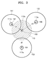
- FIG. 3 illustrates the first through third detection areas 151, 152, and 153 and the target area 170 of the object 50 at an arbitrary point of time.
- the first through third detection areas 151, 152, and 153 are located at different positions of the object 50.
- the first through third detection areas 151, 152, and 153 are exemplarily provided to be spaced apart from one another in FIG. 3 , at least one of the first through third detection areas 151, 152, and 153 may be provided to partially overlap with other detection areas.
- the first through third detection areas 151, 152, and 153 may be respectively provided to have predetermined shapes respectively about the first through third apertures 111a, 112a, and 113a.
- the target area 170 that is located at the specific position of the object 50 to be measured may be provided, but is not limited to, between the first through third detection areas 151, 152, and 153.
- the target spectrum of the target area 170 that is located at the specific position to be analyzed may be derived by using the relative position information of the first through third detection areas 151, 152, and 153 with respect to the target area 170 and the first through third detection spectrums of the first through third detection areas 151, 152, and 153.
- the relative position information of the first through third detection areas 151, 152, and 153 with respect to the target area 170 may be determined by distances d1, d2, and d3 between a center point 180 of the target area 170 and center points 182, 184, and 186 of the first through third detection areas 151, 152, and 153.
- Reference numeral 110a in FIG. 3 denotes a virtual aperture that is virtually formed to correspond to the target area 170.
- FIG. 4 is a flowchart of a spectroscopy method of analyzing an analyte of the object 50 by using the spectroscopy system 100 of FIG. 1 , according to an exemplary embodiment.
- the above-described embodiments of FIGS. 1, 2 , and 3 are applicable in an exemplary embodiment of FIG. 4 .
- detection spectrums of the plurality of detection areas that is, the first through third detection areas 151, 152, and 153 that are located at different positions are obtained.
- first through third detection spectrums of the first through third detection areas 151, 152, and 153 that are located at different positions of the object 50 in FIG. 3 are detected by the first through third detectors 111, 112, and 113.
- position information of the first through third detection areas 151, 152, and 153 is obtained.
- Relative position information of the first through third detection areas 151, 152, and 153 with respect to the target area 170 may be obtained by using the first through third displacement sensors 131, 132, and 133.
- the relative position information of the first through third detection areas 151, 152, and 153 with respect to the target area 170 may be determined by the distances d1, d2, and d3 between the target area 170 and the first through third detection areas 151, 152, and 153.
- the information processor 120 calculates a target spectrum of the target area 170 that is located at a specific position to be analyzed by using the relative position information of the first through third detection areas 151, 152, and 153 with respect to the target area 170 and the first through third detection spectrums.
- the information processor 120 linearly combines the relative position information of the first through third detection areas 151, 152, and 153 with respect to the target area 170 with the first through third detection spectrums.
- the information processor 120 calculates the target spectrum of the target area 170.
- the contribution rates ⁇ , ⁇ , and ⁇ may be determined by the relative position information of the first through third detection areas 151, 152, and 153 with respect to the target area 170.
- the contribution rates ⁇ , ⁇ , and ⁇ may be determined between the distances d1, d2, and d3 between the target area 170 and the first through third detection areas 151, 152, and 153. For example, when the first detection area 151 of the first through third detection areas 151, 152, and 153 is the closest to the target area 170, it is determined that a contribution rate of the first detection spectrum S1 of the first through third detection spectrums S1, S2, and S3 is the highest.
- the contribution rate ⁇ of the contribution rates ⁇ , ⁇ , and ⁇ may have the highest value.
- the contribution rates ⁇ , ⁇ , and ⁇ at which the first through third detection spectrums S1, S2, and S3 respectively contribute to the target spectrum ST may be determined by the distances d1, d2, and d3 between the target area 170 and the first through third detection areas 151, 152, and 153, and thus the target spectrum ST of the target area 170 that is located at the specific position to be analyzed may be obtained by using linear combination of Equation 1.
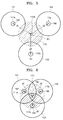
- FIG. 5 is a plan view illustrating a state in which the first through third detection areas 151, 152, and 153 and the target area 170 are arranged, according to an exemplary embodiment.
- the first through third detection areas 151, 152, and 153 are two-dimensionally arranged to be spaced apart from one another.
- the first through third detection areas 151, 152, and 153 are arranged in an equilateral triangular shape, and the target area 170 is located at a center of the equilateral triangular shape. Accordingly, the target area 170, e.g., the center point 180, is spaced apart by the same distance from the first through third detection areas 151, 152, and 153, e.g., the center points 182, 184, and 186.
- the distance d1 between the target area 170 and the first detection area 151, the distance d2 between the target area 170 and the second detection area 152, and the distance d3 between the target area 170 and the third detection area 153 are the same.
- the target spectrum ST of the target area 170 may be calculated as follows by using Equation 1 when the first through third detection areas 151, 152, and 153 and the target area 170 are arranged as shown in FIG. 5 .
- the first through third detection spectrums S1, S2, and S2 of the first through third detection areas 151, 152, and 153 are respectively detected by the first through third detectors 111, 112, and 113.
- the contribution rates ⁇ , ⁇ , and ⁇ at which the first through third detection spectrums S1, S2, and S3 respectively contribute to the target spectrum ST are determined by using the relative position information of the first through third detection areas 151, 152, and 153 with respect to the target area 170. For example, when the distance d1 between the target area 170 and the first detection area 151, the distance d2 between the target area 170 and the second detection area 152, and the distance d3 between the target area 170 and the third detection area 153 are the same, the contribution rates ⁇ , ⁇ , and ⁇ at which the first through third detection spectrums S1, S2, and S3 respectively contribute to the target spectrum ST are also the same.
- each of the contribution rates ⁇ , ⁇ , and ⁇ in Equation 1 is 1/3.
- the target spectrum ST of the target area 170 may be calculated as 1/3 x S1 + 1/3 x S2 + 1/3 x S3.
- FIG. 6 is a plan view illustrating the first through third detection areas 151, 152, and 153 and the target area 170, according to another exemplary embodiment.
- FIG. 6 is the same as FIG. 5 except that the first through third detection areas 151, 152, and 153 partially overlap with one another.
- the first through third detectors 111, 112, and 113 may sequentially detect the first through third detection spectrums S1, S2, and S3 at predetermined intervals.
- an exemplary embodiment is not limited thereto, and the first through third detection spectrums S1, S2, and S3 may be simultaneously detected. Since the distance d1 between the target area 170 and the first detection area 151, the distance d2 between the target area 170 and the second detection area 152, and the distance d3 between the target area 170 and the third detection area 153 are the same in FIG.
- the target spectrum ST of the target area 170 that is located at the specific position to be measured may be calculated as 1/3 x S1 + 1/3 x S2 + 1/3 x S3.
- FIG. 7 is a plan view illustrating the first through third detection areas 151, 152, and 153 and the target area 170, according to another exemplary embodiment.
- the first through third detection areas 151, 152, and 153 are two-dimensionally arranged to partially overlap with one another. However, the first through third detection areas 151, 152, and 153 may be provided to be spaced apart from one another. In FIG. 7 , the target area 170 entirely coincides with the first detection area 151.
- the target spectrum ST of the target area 170 may be calculated as follows by using Equation 1. First, the first through third detection spectrums S1, S2, and S3 of the first through third detection areas 151, 152, and 153 are detected by using the first through third detectors 111, 112, and 113. Next, the contribution rates ⁇ , ⁇ , and ⁇ at which the first through third detection spectrums S1, S2, and S3 respectively contribute to the target spectrum ST are determined by using the relative position information of the first through third detection areas 151, 152, and 153 with respect to the target area 170.
- the target area 170 coincides with the first detection area 151, the contribution rate ⁇ at which the first detection spectrum S1 contributes to the target spectrum ST is 1, and the contribution rates ⁇ and ⁇ at which the second and third detection spectrums S2 and S2 respectively contribute to the target spectrum ST are 0.
- the target spectrum ST of the target area 170 that is located at the specific position to be measured in FIG. 7 is the same as the first detection spectrum S 1.
- the target spectrum ST of the target area 170 that is located at the specific position to be measured may be calculated by using the first through third detection spectrums S1, S2, and S3 of the first through third detection areas 151, 152, and 153 and the relative position information of the first through third detection areas 151, 152, and 153 with respect to the target area 170.
- the target spectrum ST of the target area 170 may be calculated when four or more detection areas are two-dimensionally arranged.
- the target spectrum ST of the target area 170 that is located at the specific position to be measured may be calculated by compensating for the position change by using the position information of the first through third detection areas 151, 152, and 153.
- an analyte of the object 50 in the target area 170 may be analyzed by analyzing the target spectrum ST that is calculated by the information processor 120. That is, the target spectrum ST that is calculated by linearly combining the relative position information of the first through third detection areas 151, 152, and 153 with respect to the target area 170 with the first through third detection spectrums S1, S2, and S3 of the first through third detection areas 151, 152, and 153 may be used to analyze the analyte of the object 50 that is located at the specific position to be measured at a specific point of time.
- ⁇ w n 1 .
- a target spectrum of a target area may be derived by using position information of detection areas that are located at different positions of an object and detection spectrums of the detection areas. Accordingly, even when positions of the detection areas of the object are changed as time passes, the target spectrum of the target area that is located at a specific position to be measured may be obtained by compensating for the position change. Accordingly, when the object is, for example, the skin of a human, positions of detection areas may be changed as the skin of the human moves. However, a blood glucose spectrum at a specific position may be calculated in real time by linearly combining displacement information of the detection areas with measured blood glucose spectrums of the detection areas.
Landscapes
- Health & Medical Sciences (AREA)
- Physics & Mathematics (AREA)
- Life Sciences & Earth Sciences (AREA)
- Spectroscopy & Molecular Physics (AREA)
- Pathology (AREA)
- General Health & Medical Sciences (AREA)
- General Physics & Mathematics (AREA)
- Engineering & Computer Science (AREA)
- Biomedical Technology (AREA)
- Heart & Thoracic Surgery (AREA)
- Medical Informatics (AREA)
- Molecular Biology (AREA)
- Surgery (AREA)
- Animal Behavior & Ethology (AREA)
- Biophysics (AREA)
- Public Health (AREA)
- Veterinary Medicine (AREA)
- Analytical Chemistry (AREA)
- Immunology (AREA)
- Chemical & Material Sciences (AREA)
- Biochemistry (AREA)
- Nuclear Medicine, Radiotherapy & Molecular Imaging (AREA)
- Emergency Medicine (AREA)
- Dermatology (AREA)
- Optics & Photonics (AREA)
- Physiology (AREA)
- Dentistry (AREA)
- Oral & Maxillofacial Surgery (AREA)
- Investigating, Analyzing Materials By Fluorescence Or Luminescence (AREA)
- Investigating Or Analysing Materials By Optical Means (AREA)
- Measurement Of The Respiration, Hearing Ability, Form, And Blood Characteristics Of Living Organisms (AREA)
Applications Claiming Priority (1)
| Application Number | Priority Date | Filing Date | Title |
|---|---|---|---|
| KR1020140154735A KR102323212B1 (ko) | 2014-11-07 | 2014-11-07 | 위치 변동을 보상할 수 있는 분광 시스템 및 이를 이용한 분광 방법 |
Publications (2)
| Publication Number | Publication Date |
|---|---|
| EP3021095A1 true EP3021095A1 (fr) | 2016-05-18 |
| EP3021095B1 EP3021095B1 (fr) | 2020-06-03 |
Family
ID=54476793
Family Applications (1)
| Application Number | Title | Priority Date | Filing Date |
|---|---|---|---|
| EP15193113.6A Active EP3021095B1 (fr) | 2014-11-07 | 2015-11-05 | Système de spectroscopie avec compensation de déplacement et procédé de spectroscopie utilisant ledit système |
Country Status (3)
| Country | Link |
|---|---|
| US (1) | US9599509B2 (fr) |
| EP (1) | EP3021095B1 (fr) |
| KR (1) | KR102323212B1 (fr) |
Families Citing this family (4)
| Publication number | Priority date | Publication date | Assignee | Title |
|---|---|---|---|---|
| WO2016054079A1 (fr) | 2014-09-29 | 2016-04-07 | Zyomed Corp. | Systèmes et procédés pour la détection et la mesure du glucose sanguin du sang et d'autres analytes à l'aide du calcul de collision |
| US9554738B1 (en) | 2016-03-30 | 2017-01-31 | Zyomed Corp. | Spectroscopic tomography systems and methods for noninvasive detection and measurement of analytes using collision computing |
| KR102282395B1 (ko) * | 2019-12-17 | 2021-07-26 | 국민대학교산학협력단 | 다중 옵셋 프로브 및 이를 포함하는 다층 물질 분석 장치 |
| CN117617962A (zh) * | 2023-12-25 | 2024-03-01 | 暨南大学 | 一种基于空间偏移拉曼的皮下血糖测量方法 |
Citations (5)
| Publication number | Priority date | Publication date | Assignee | Title |
|---|---|---|---|---|
| US20060181543A1 (en) * | 2003-10-07 | 2006-08-17 | Olympus Corporation | Image display apparatus and image display method |
| US20070002276A1 (en) * | 2004-12-03 | 2007-01-04 | Topcon Corporation | Apparatus and method for measuring spectrum image data of eyeground |
| US20070081156A1 (en) * | 2005-10-07 | 2007-04-12 | Chemimage Corporation | System and method for a chemical imaging threat assessor with a probe |
| US20140253924A1 (en) * | 2013-03-07 | 2014-09-11 | Seiko Epson Corporation | Spectrometer |
| WO2015017623A1 (fr) * | 2013-08-02 | 2015-02-05 | Tsi, Inc. | Ensemble capteur spectroscopique rapide et système |
Family Cites Families (7)
| Publication number | Priority date | Publication date | Assignee | Title |
|---|---|---|---|---|
| JP3443688B2 (ja) | 1992-08-21 | 2003-09-08 | 憲一 山越 | 非観血血圧及び血液酸素飽和度同時連続測定装置 |
| WO2004011963A2 (fr) | 2002-07-26 | 2004-02-05 | Lockheed Martin Corporation | Spectrometrie a transformee de fourrier a interferometre multi-ouverture |
| US8787630B2 (en) | 2004-08-11 | 2014-07-22 | Lumidigm, Inc. | Multispectral barcode imaging |
| GB0426993D0 (en) * | 2004-12-09 | 2005-01-12 | Council Cent Lab Res Councils | Apparatus for depth-selective raman spectroscopy |
| US7973937B1 (en) | 2006-08-18 | 2011-07-05 | Lockheed Martin Corporation | Near field suppression with a multi-aperture imaging system |
| JP2014519130A (ja) * | 2011-06-06 | 2014-08-07 | シクパ ホルディング ソシエテ アノニム | インライン減衰時間スキャナ |
| JP2013228322A (ja) | 2012-04-26 | 2013-11-07 | Japan Atomic Energy Agency | 分光装置 |
-
2014
- 2014-11-07 KR KR1020140154735A patent/KR102323212B1/ko active Active
-
2015
- 2015-11-05 EP EP15193113.6A patent/EP3021095B1/fr active Active
- 2015-11-06 US US14/934,722 patent/US9599509B2/en active Active
Patent Citations (5)
| Publication number | Priority date | Publication date | Assignee | Title |
|---|---|---|---|---|
| US20060181543A1 (en) * | 2003-10-07 | 2006-08-17 | Olympus Corporation | Image display apparatus and image display method |
| US20070002276A1 (en) * | 2004-12-03 | 2007-01-04 | Topcon Corporation | Apparatus and method for measuring spectrum image data of eyeground |
| US20070081156A1 (en) * | 2005-10-07 | 2007-04-12 | Chemimage Corporation | System and method for a chemical imaging threat assessor with a probe |
| US20140253924A1 (en) * | 2013-03-07 | 2014-09-11 | Seiko Epson Corporation | Spectrometer |
| WO2015017623A1 (fr) * | 2013-08-02 | 2015-02-05 | Tsi, Inc. | Ensemble capteur spectroscopique rapide et système |
Also Published As
| Publication number | Publication date |
|---|---|
| KR102323212B1 (ko) | 2021-11-09 |
| EP3021095B1 (fr) | 2020-06-03 |
| KR20160055009A (ko) | 2016-05-17 |
| US9599509B2 (en) | 2017-03-21 |
| US20160131523A1 (en) | 2016-05-12 |
Similar Documents
| Publication | Publication Date | Title |
|---|---|---|
| EP3021095B1 (fr) | Système de spectroscopie avec compensation de déplacement et procédé de spectroscopie utilisant ledit système | |
| Wei et al. | A novel 1D target-based calibration method with unknown orientation for structured light vision sensor | |
| Soileau et al. | Automated anthropometric phenotyping with novel Kinect-based three-dimensional imaging method: comparison with a reference laser imaging system | |
| Kroos | Evaluation of the measurement precision in three-dimensional electromagnetic articulography (Carstens AG500) | |
| Alshareef et al. | Application of trilateration and Kalman filtering algorithms to track dynamic brain deformation using sonomicrometry | |
| US12096991B2 (en) | Position determining device for determining the position of an object within a tubular structure | |
| EP2420796B1 (fr) | Procédé de mesure de forme et appareil de mesure de forme utilisant interférometrie à lumière blanche | |
| Amin et al. | Routine application of Raman spectroscopy in the quality control of hospital compounded ganciclovir | |
| Möltgen et al. | A novel multivariate approach using science-based calibration for direct coating thickness determination in real-time NIR process monitoring | |
| US9194823B2 (en) | Radiation inspection apparatus | |
| US10548517B2 (en) | Spectroscopic apparatus for biological material and spectroscopic method using the same | |
| JP6492103B2 (ja) | 生体内信号源位置検出方法及び生体内信号源位置検出装置 | |
| US10506942B2 (en) | In-vivo signal source detection method and in-vivo signal source detection device | |
| Jiang et al. | Separation of thoracic and abdominal measurements in neonatal vital sign monitoring using radar vision fusion system | |
| EP3187821A1 (fr) | Processeur de données et procédé de traitement de données | |
| EP3871609A4 (fr) | Sonde de débit sanguin, capteur de débit sanguin et instrument de mesure de débit sanguin | |
| EP2765393B1 (fr) | Codeur linéaire séparé | |
| JP4431705B2 (ja) | 粒径分布測定装置 | |
| JP2003329430A (ja) | 被検査物の厚さ測定方法 | |
| Jia et al. | Application to SSVEP of chirp stimulus using non-harmonic analysis | |
| Zhu | Locating and extracting acoustic and neural signals | |
| JP7117727B2 (ja) | 生体内信号源位置検出方法 | |
| CN117982111A (zh) | 脉压测量设备 | |
| Di | Space curve fitting method based on fiber-optic curvature gages | |
| Kaushik et al. | Three dimensional microphone and source position estimation using TDOA and TOF measurements |
Legal Events
| Date | Code | Title | Description |
|---|---|---|---|
| PUAI | Public reference made under article 153(3) epc to a published international application that has entered the european phase |
Free format text: ORIGINAL CODE: 0009012 |
|
| AK | Designated contracting states |
Kind code of ref document: A1 Designated state(s): AL AT BE BG CH CY CZ DE DK EE ES FI FR GB GR HR HU IE IS IT LI LT LU LV MC MK MT NL NO PL PT RO RS SE SI SK SM TR |
|
| AX | Request for extension of the european patent |
Extension state: BA ME |
|
| STAA | Information on the status of an ep patent application or granted ep patent |
Free format text: STATUS: REQUEST FOR EXAMINATION WAS MADE |
|
| 17P | Request for examination filed |
Effective date: 20161110 |
|
| RBV | Designated contracting states (corrected) |
Designated state(s): AL AT BE BG CH CY CZ DE DK EE ES FI FR GB GR HR HU IE IS IT LI LT LU LV MC MK MT NL NO PL PT RO RS SE SI SK SM TR |
|
| STAA | Information on the status of an ep patent application or granted ep patent |
Free format text: STATUS: EXAMINATION IS IN PROGRESS |
|
| 17Q | First examination report despatched |
Effective date: 20180706 |
|
| GRAP | Despatch of communication of intention to grant a patent |
Free format text: ORIGINAL CODE: EPIDOSNIGR1 |
|
| STAA | Information on the status of an ep patent application or granted ep patent |
Free format text: STATUS: GRANT OF PATENT IS INTENDED |
|
| GRAS | Grant fee paid |
Free format text: ORIGINAL CODE: EPIDOSNIGR3 |
|
| GRAJ | Information related to disapproval of communication of intention to grant by the applicant or resumption of examination proceedings by the epo deleted |
Free format text: ORIGINAL CODE: EPIDOSDIGR1 |
|
| GRAL | Information related to payment of fee for publishing/printing deleted |
Free format text: ORIGINAL CODE: EPIDOSDIGR3 |
|
| STAA | Information on the status of an ep patent application or granted ep patent |
Free format text: STATUS: EXAMINATION IS IN PROGRESS |
|
| INTG | Intention to grant announced |
Effective date: 20200310 |
|
| GRAR | Information related to intention to grant a patent recorded |
Free format text: ORIGINAL CODE: EPIDOSNIGR71 |
|
| STAA | Information on the status of an ep patent application or granted ep patent |
Free format text: STATUS: GRANT OF PATENT IS INTENDED |
|
| GRAA | (expected) grant |
Free format text: ORIGINAL CODE: 0009210 |
|
| STAA | Information on the status of an ep patent application or granted ep patent |
Free format text: STATUS: THE PATENT HAS BEEN GRANTED |
|
| INTC | Intention to grant announced (deleted) | ||
| AK | Designated contracting states |
Kind code of ref document: B1 Designated state(s): AL AT BE BG CH CY CZ DE DK EE ES FI FR GB GR HR HU IE IS IT LI LT LU LV MC MK MT NL NO PL PT RO RS SE SI SK SM TR |
|
| INTG | Intention to grant announced |
Effective date: 20200427 |
|
| REG | Reference to a national code |
Ref country code: GB Ref legal event code: FG4D |
|
| REG | Reference to a national code |
Ref country code: CH Ref legal event code: EP Ref country code: AT Ref legal event code: REF Ref document number: 1277491 Country of ref document: AT Kind code of ref document: T Effective date: 20200615 |
|
| REG | Reference to a national code |
Ref country code: DE Ref legal event code: R096 Ref document number: 602015053670 Country of ref document: DE |
|
| REG | Reference to a national code |
Ref country code: LT Ref legal event code: MG4D |
|
| PG25 | Lapsed in a contracting state [announced via postgrant information from national office to epo] |
Ref country code: FI Free format text: LAPSE BECAUSE OF FAILURE TO SUBMIT A TRANSLATION OF THE DESCRIPTION OR TO PAY THE FEE WITHIN THE PRESCRIBED TIME-LIMIT Effective date: 20200603 Ref country code: LT Free format text: LAPSE BECAUSE OF FAILURE TO SUBMIT A TRANSLATION OF THE DESCRIPTION OR TO PAY THE FEE WITHIN THE PRESCRIBED TIME-LIMIT Effective date: 20200603 Ref country code: SE Free format text: LAPSE BECAUSE OF FAILURE TO SUBMIT A TRANSLATION OF THE DESCRIPTION OR TO PAY THE FEE WITHIN THE PRESCRIBED TIME-LIMIT Effective date: 20200603 Ref country code: NO Free format text: LAPSE BECAUSE OF FAILURE TO SUBMIT A TRANSLATION OF THE DESCRIPTION OR TO PAY THE FEE WITHIN THE PRESCRIBED TIME-LIMIT Effective date: 20200903 Ref country code: GR Free format text: LAPSE BECAUSE OF FAILURE TO SUBMIT A TRANSLATION OF THE DESCRIPTION OR TO PAY THE FEE WITHIN THE PRESCRIBED TIME-LIMIT Effective date: 20200904 |
|
| REG | Reference to a national code |
Ref country code: NL Ref legal event code: MP Effective date: 20200603 |
|
| PG25 | Lapsed in a contracting state [announced via postgrant information from national office to epo] |
Ref country code: RS Free format text: LAPSE BECAUSE OF FAILURE TO SUBMIT A TRANSLATION OF THE DESCRIPTION OR TO PAY THE FEE WITHIN THE PRESCRIBED TIME-LIMIT Effective date: 20200603 Ref country code: HR Free format text: LAPSE BECAUSE OF FAILURE TO SUBMIT A TRANSLATION OF THE DESCRIPTION OR TO PAY THE FEE WITHIN THE PRESCRIBED TIME-LIMIT Effective date: 20200603 Ref country code: BG Free format text: LAPSE BECAUSE OF FAILURE TO SUBMIT A TRANSLATION OF THE DESCRIPTION OR TO PAY THE FEE WITHIN THE PRESCRIBED TIME-LIMIT Effective date: 20200903 Ref country code: LV Free format text: LAPSE BECAUSE OF FAILURE TO SUBMIT A TRANSLATION OF THE DESCRIPTION OR TO PAY THE FEE WITHIN THE PRESCRIBED TIME-LIMIT Effective date: 20200603 |
|
| REG | Reference to a national code |
Ref country code: AT Ref legal event code: MK05 Ref document number: 1277491 Country of ref document: AT Kind code of ref document: T Effective date: 20200603 |
|
| PG25 | Lapsed in a contracting state [announced via postgrant information from national office to epo] |
Ref country code: AL Free format text: LAPSE BECAUSE OF FAILURE TO SUBMIT A TRANSLATION OF THE DESCRIPTION OR TO PAY THE FEE WITHIN THE PRESCRIBED TIME-LIMIT Effective date: 20200603 Ref country code: NL Free format text: LAPSE BECAUSE OF FAILURE TO SUBMIT A TRANSLATION OF THE DESCRIPTION OR TO PAY THE FEE WITHIN THE PRESCRIBED TIME-LIMIT Effective date: 20200603 |
|
| PG25 | Lapsed in a contracting state [announced via postgrant information from national office to epo] |
Ref country code: CZ Free format text: LAPSE BECAUSE OF FAILURE TO SUBMIT A TRANSLATION OF THE DESCRIPTION OR TO PAY THE FEE WITHIN THE PRESCRIBED TIME-LIMIT Effective date: 20200603 Ref country code: ES Free format text: LAPSE BECAUSE OF FAILURE TO SUBMIT A TRANSLATION OF THE DESCRIPTION OR TO PAY THE FEE WITHIN THE PRESCRIBED TIME-LIMIT Effective date: 20200603 Ref country code: RO Free format text: LAPSE BECAUSE OF FAILURE TO SUBMIT A TRANSLATION OF THE DESCRIPTION OR TO PAY THE FEE WITHIN THE PRESCRIBED TIME-LIMIT Effective date: 20200603 Ref country code: IT Free format text: LAPSE BECAUSE OF FAILURE TO SUBMIT A TRANSLATION OF THE DESCRIPTION OR TO PAY THE FEE WITHIN THE PRESCRIBED TIME-LIMIT Effective date: 20200603 Ref country code: AT Free format text: LAPSE BECAUSE OF FAILURE TO SUBMIT A TRANSLATION OF THE DESCRIPTION OR TO PAY THE FEE WITHIN THE PRESCRIBED TIME-LIMIT Effective date: 20200603 Ref country code: EE Free format text: LAPSE BECAUSE OF FAILURE TO SUBMIT A TRANSLATION OF THE DESCRIPTION OR TO PAY THE FEE WITHIN THE PRESCRIBED TIME-LIMIT Effective date: 20200603 Ref country code: SM Free format text: LAPSE BECAUSE OF FAILURE TO SUBMIT A TRANSLATION OF THE DESCRIPTION OR TO PAY THE FEE WITHIN THE PRESCRIBED TIME-LIMIT Effective date: 20200603 Ref country code: PT Free format text: LAPSE BECAUSE OF FAILURE TO SUBMIT A TRANSLATION OF THE DESCRIPTION OR TO PAY THE FEE WITHIN THE PRESCRIBED TIME-LIMIT Effective date: 20201006 |
|
| PG25 | Lapsed in a contracting state [announced via postgrant information from national office to epo] |
Ref country code: SK Free format text: LAPSE BECAUSE OF FAILURE TO SUBMIT A TRANSLATION OF THE DESCRIPTION OR TO PAY THE FEE WITHIN THE PRESCRIBED TIME-LIMIT Effective date: 20200603 Ref country code: PL Free format text: LAPSE BECAUSE OF FAILURE TO SUBMIT A TRANSLATION OF THE DESCRIPTION OR TO PAY THE FEE WITHIN THE PRESCRIBED TIME-LIMIT Effective date: 20200603 Ref country code: IS Free format text: LAPSE BECAUSE OF FAILURE TO SUBMIT A TRANSLATION OF THE DESCRIPTION OR TO PAY THE FEE WITHIN THE PRESCRIBED TIME-LIMIT Effective date: 20201003 |
|
| REG | Reference to a national code |
Ref country code: DE Ref legal event code: R097 Ref document number: 602015053670 Country of ref document: DE |
|
| PLBE | No opposition filed within time limit |
Free format text: ORIGINAL CODE: 0009261 |
|
| STAA | Information on the status of an ep patent application or granted ep patent |
Free format text: STATUS: NO OPPOSITION FILED WITHIN TIME LIMIT |
|
| PG25 | Lapsed in a contracting state [announced via postgrant information from national office to epo] |
Ref country code: DK Free format text: LAPSE BECAUSE OF FAILURE TO SUBMIT A TRANSLATION OF THE DESCRIPTION OR TO PAY THE FEE WITHIN THE PRESCRIBED TIME-LIMIT Effective date: 20200603 |
|
| 26N | No opposition filed |
Effective date: 20210304 |
|
| PG25 | Lapsed in a contracting state [announced via postgrant information from national office to epo] |
Ref country code: SI Free format text: LAPSE BECAUSE OF FAILURE TO SUBMIT A TRANSLATION OF THE DESCRIPTION OR TO PAY THE FEE WITHIN THE PRESCRIBED TIME-LIMIT Effective date: 20200603 |
|
| PG25 | Lapsed in a contracting state [announced via postgrant information from national office to epo] |
Ref country code: MC Free format text: LAPSE BECAUSE OF FAILURE TO SUBMIT A TRANSLATION OF THE DESCRIPTION OR TO PAY THE FEE WITHIN THE PRESCRIBED TIME-LIMIT Effective date: 20200603 |
|
| REG | Reference to a national code |
Ref country code: CH Ref legal event code: PL |
|
| PG25 | Lapsed in a contracting state [announced via postgrant information from national office to epo] |
Ref country code: LU Free format text: LAPSE BECAUSE OF NON-PAYMENT OF DUE FEES Effective date: 20201105 |
|
| REG | Reference to a national code |
Ref country code: BE Ref legal event code: MM Effective date: 20201130 |
|
| PG25 | Lapsed in a contracting state [announced via postgrant information from national office to epo] |
Ref country code: CH Free format text: LAPSE BECAUSE OF NON-PAYMENT OF DUE FEES Effective date: 20201130 Ref country code: LI Free format text: LAPSE BECAUSE OF NON-PAYMENT OF DUE FEES Effective date: 20201130 |
|
| PG25 | Lapsed in a contracting state [announced via postgrant information from national office to epo] |
Ref country code: IE Free format text: LAPSE BECAUSE OF NON-PAYMENT OF DUE FEES Effective date: 20201105 |
|
| PG25 | Lapsed in a contracting state [announced via postgrant information from national office to epo] |
Ref country code: TR Free format text: LAPSE BECAUSE OF FAILURE TO SUBMIT A TRANSLATION OF THE DESCRIPTION OR TO PAY THE FEE WITHIN THE PRESCRIBED TIME-LIMIT Effective date: 20200603 Ref country code: MT Free format text: LAPSE BECAUSE OF FAILURE TO SUBMIT A TRANSLATION OF THE DESCRIPTION OR TO PAY THE FEE WITHIN THE PRESCRIBED TIME-LIMIT Effective date: 20200603 Ref country code: CY Free format text: LAPSE BECAUSE OF FAILURE TO SUBMIT A TRANSLATION OF THE DESCRIPTION OR TO PAY THE FEE WITHIN THE PRESCRIBED TIME-LIMIT Effective date: 20200603 |
|
| PG25 | Lapsed in a contracting state [announced via postgrant information from national office to epo] |
Ref country code: MK Free format text: LAPSE BECAUSE OF FAILURE TO SUBMIT A TRANSLATION OF THE DESCRIPTION OR TO PAY THE FEE WITHIN THE PRESCRIBED TIME-LIMIT Effective date: 20200603 |
|
| PG25 | Lapsed in a contracting state [announced via postgrant information from national office to epo] |
Ref country code: BE Free format text: LAPSE BECAUSE OF NON-PAYMENT OF DUE FEES Effective date: 20201130 |
|
| PGFP | Annual fee paid to national office [announced via postgrant information from national office to epo] |
Ref country code: DE Payment date: 20251022 Year of fee payment: 11 |
|
| PGFP | Annual fee paid to national office [announced via postgrant information from national office to epo] |
Ref country code: GB Payment date: 20251016 Year of fee payment: 11 |
|
| PGFP | Annual fee paid to national office [announced via postgrant information from national office to epo] |
Ref country code: FR Payment date: 20251023 Year of fee payment: 11 |