EP3021381A1 - Système de batterie permettant d'améliorer la fiabilité de fonctionnement de cid en expansion - Google Patents
Système de batterie permettant d'améliorer la fiabilité de fonctionnement de cid en expansion Download PDFInfo
- Publication number
- EP3021381A1 EP3021381A1 EP15179917.8A EP15179917A EP3021381A1 EP 3021381 A1 EP3021381 A1 EP 3021381A1 EP 15179917 A EP15179917 A EP 15179917A EP 3021381 A1 EP3021381 A1 EP 3021381A1
- Authority
- EP
- European Patent Office
- Prior art keywords
- swelling
- battery
- battery system
- cid
- pouch
- Prior art date
- Legal status (The legal status is an assumption and is not a legal conclusion. Google has not performed a legal analysis and makes no representation as to the accuracy of the status listed.)
- Granted
Links
Images


Classifications
-
- H—ELECTRICITY
- H01—ELECTRIC ELEMENTS
- H01M—PROCESSES OR MEANS, e.g. BATTERIES, FOR THE DIRECT CONVERSION OF CHEMICAL ENERGY INTO ELECTRICAL ENERGY
- H01M10/00—Secondary cells; Manufacture thereof
- H01M10/60—Heating or cooling; Temperature control
- H01M10/64—Heating or cooling; Temperature control characterised by the shape of the cells
- H01M10/647—Prismatic or flat cells, e.g. pouch cells
-
- H—ELECTRICITY
- H01—ELECTRIC ELEMENTS
- H01M—PROCESSES OR MEANS, e.g. BATTERIES, FOR THE DIRECT CONVERSION OF CHEMICAL ENERGY INTO ELECTRICAL ENERGY
- H01M10/00—Secondary cells; Manufacture thereof
- H01M10/60—Heating or cooling; Temperature control
- H01M10/65—Means for temperature control structurally associated with the cells
- H01M10/655—Solid structures for heat exchange or heat conduction
-
- H—ELECTRICITY
- H01—ELECTRIC ELEMENTS
- H01M—PROCESSES OR MEANS, e.g. BATTERIES, FOR THE DIRECT CONVERSION OF CHEMICAL ENERGY INTO ELECTRICAL ENERGY
- H01M10/00—Secondary cells; Manufacture thereof
- H01M10/60—Heating or cooling; Temperature control
- H01M10/65—Means for temperature control structurally associated with the cells
- H01M10/655—Solid structures for heat exchange or heat conduction
- H01M10/6554—Rods or plates
- H01M10/6555—Rods or plates arranged between the cells
-
- H—ELECTRICITY
- H01—ELECTRIC ELEMENTS
- H01M—PROCESSES OR MEANS, e.g. BATTERIES, FOR THE DIRECT CONVERSION OF CHEMICAL ENERGY INTO ELECTRICAL ENERGY
- H01M50/00—Constructional details or processes of manufacture of the non-active parts of electrochemical cells other than fuel cells, e.g. hybrid cells
- H01M50/10—Primary casings; Jackets or wrappings
- H01M50/102—Primary casings; Jackets or wrappings characterised by their shape or physical structure
- H01M50/105—Pouches or flexible bags
-
- H—ELECTRICITY
- H01—ELECTRIC ELEMENTS
- H01M—PROCESSES OR MEANS, e.g. BATTERIES, FOR THE DIRECT CONVERSION OF CHEMICAL ENERGY INTO ELECTRICAL ENERGY
- H01M50/00—Constructional details or processes of manufacture of the non-active parts of electrochemical cells other than fuel cells, e.g. hybrid cells
- H01M50/10—Primary casings; Jackets or wrappings
- H01M50/172—Arrangements of electric connectors penetrating the casing
- H01M50/174—Arrangements of electric connectors penetrating the casing adapted for the shape of the cells
- H01M50/178—Arrangements of electric connectors penetrating the casing adapted for the shape of the cells for pouch or flexible bag cells
-
- H—ELECTRICITY
- H01—ELECTRIC ELEMENTS
- H01M—PROCESSES OR MEANS, e.g. BATTERIES, FOR THE DIRECT CONVERSION OF CHEMICAL ENERGY INTO ELECTRICAL ENERGY
- H01M50/00—Constructional details or processes of manufacture of the non-active parts of electrochemical cells other than fuel cells, e.g. hybrid cells
- H01M50/50—Current conducting connections for cells or batteries
- H01M50/531—Electrode connections inside a battery casing
- H01M50/533—Electrode connections inside a battery casing characterised by the shape of the leads or tabs
-
- H—ELECTRICITY
- H01—ELECTRIC ELEMENTS
- H01M—PROCESSES OR MEANS, e.g. BATTERIES, FOR THE DIRECT CONVERSION OF CHEMICAL ENERGY INTO ELECTRICAL ENERGY
- H01M50/00—Constructional details or processes of manufacture of the non-active parts of electrochemical cells other than fuel cells, e.g. hybrid cells
- H01M50/50—Current conducting connections for cells or batteries
- H01M50/572—Means for preventing undesired use or discharge
- H01M50/574—Devices or arrangements for the interruption of current
-
- H—ELECTRICITY
- H01—ELECTRIC ELEMENTS
- H01M—PROCESSES OR MEANS, e.g. BATTERIES, FOR THE DIRECT CONVERSION OF CHEMICAL ENERGY INTO ELECTRICAL ENERGY
- H01M50/00—Constructional details or processes of manufacture of the non-active parts of electrochemical cells other than fuel cells, e.g. hybrid cells
- H01M50/50—Current conducting connections for cells or batteries
- H01M50/572—Means for preventing undesired use or discharge
- H01M50/574—Devices or arrangements for the interruption of current
- H01M50/578—Devices or arrangements for the interruption of current in response to pressure
-
- H—ELECTRICITY
- H01—ELECTRIC ELEMENTS
- H01M—PROCESSES OR MEANS, e.g. BATTERIES, FOR THE DIRECT CONVERSION OF CHEMICAL ENERGY INTO ELECTRICAL ENERGY
- H01M2200/00—Safety devices for primary or secondary batteries
- H01M2200/20—Pressure-sensitive devices
-
- H—ELECTRICITY
- H01—ELECTRIC ELEMENTS
- H01M—PROCESSES OR MEANS, e.g. BATTERIES, FOR THE DIRECT CONVERSION OF CHEMICAL ENERGY INTO ELECTRICAL ENERGY
- H01M2220/00—Batteries for particular applications
- H01M2220/20—Batteries in motive systems, e.g. vehicle, ship, plane
-
- Y—GENERAL TAGGING OF NEW TECHNOLOGICAL DEVELOPMENTS; GENERAL TAGGING OF CROSS-SECTIONAL TECHNOLOGIES SPANNING OVER SEVERAL SECTIONS OF THE IPC; TECHNICAL SUBJECTS COVERED BY FORMER USPC CROSS-REFERENCE ART COLLECTIONS [XRACs] AND DIGESTS
- Y02—TECHNOLOGIES OR APPLICATIONS FOR MITIGATION OR ADAPTATION AGAINST CLIMATE CHANGE
- Y02E—REDUCTION OF GREENHOUSE GAS [GHG] EMISSIONS, RELATED TO ENERGY GENERATION, TRANSMISSION OR DISTRIBUTION
- Y02E60/00—Enabling technologies; Technologies with a potential or indirect contribution to GHG emissions mitigation
- Y02E60/10—Energy storage using batteries
Definitions
- the present disclosure relates to a battery system that improves operation reliability of a swelling current interrupt device (CID), and more particularly, to a battery system that improves operation reliability of a swelling CID, which allows the swelling CID to be normally operated regardless of a pouch cell size.
- CID swelling current interrupt device
- operation reliability of a swelling CID embedded in a pouch cell within a vehicle depends on a size of the pouch cell, more particularly, a thickness of the pouch cell, due to a design structure of pouch cells which are adhered to a cooling plate in a thickness direction.
- a swelling (e.g., expansion) thickness is restricted by the cooling plate.
- a pouch cell has a substantially thick thickness, since substantial swelling space is present between the cooling plates, a swelling delay phenomenon may occur.
- An aspect of the present disclosure provides a battery system that may improve operation reliability of a swelling CID, and may allow the swelling CID to be operated normally regardless of a pouch cell size, by improving a structure of a cooling plate mounted external to the pouch cell.
- a battery system improving operation reliability of a swelling current interrupt device may include a cooling plate configured to form an appearance of a battery in which the swelling CID configured to interrupt a current flow may be mounted and may have a swelling aperture formed therein, wherein the swelling aperture may induce an expansion of a pouch in which the swelling CID is embedded.
- vehicle or “vehicular” or other similar term as used herein is inclusive of motor vehicles in general such as passenger automobiles including sports utility vehicles (SUV), buses, trucks, various commercial vehicles, watercraft including a variety of boats and ships, aircraft, and the like, and includes hybrid vehicles, electric vehicles, combustion, plug-in hybrid electric vehicles, hydrogen-powered vehicles and other alternative fuel vehicles (e.g. fuels derived from resources other than petroleum).
- motor vehicles in general such as passenger automobiles including sports utility vehicles (SUV), buses, trucks, various commercial vehicles, watercraft including a variety of boats and ships, aircraft, and the like, and includes hybrid vehicles, electric vehicles, combustion, plug-in hybrid electric vehicles, hydrogen-powered vehicles and other alternative fuel vehicles (e.g. fuels derived from resources other than petroleum).
- SUV sports utility vehicles
- plug-in hybrid electric vehicles e.g. fuels derived from resources other than petroleum
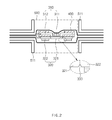
- a battery system improving operation reliability of a swelling CID including a battery part 100, a lead tab 200 configured to connect the battery part 100 to the exterior, a swelling current interrupt device (CID) 300 disposed between the battery part 100 and the lead tab 200, and a pouch 400 configured to package (e.g., house, enclose, etc.) the battery part 100 and the swelling CID 300, may include a cooling plate 500 configured to be adhered to the pouch 400 to cool the battery part 100, wherein a swelling aperture 510 allowing an expansion of the pouch 400 to be concentrated may be formed in the cooling plate 500.
- a cooling plate 500 configured to be adhered to the pouch 400 to cool the battery part 100, wherein a swelling aperture 510 allowing an expansion of the pouch 400 to be concentrated may be formed in the cooling plate 500.
- the battery part 100 may be manufactured in a wound jelly shape which is widely known as a jelly roll.
- the lead tab 200 may be provided to both ends of the battery part 100 in a width direction of the battery part 100.
- the pouch 400 may include a center part 410 that covers the battery part 100 and an edge part 420 extended from the center part 410.
- the cooling plate 500 may be manufactured in a plate shape having about the same area as that of the pouch 400, and may be disposed on each of upper and lower surfaces of the pouch 400.
- the cooling plate 500 may include a swelling suppression part 520 which is in contact with the edge part 420 and may protrude from the cooling plate 500 to the edge part 420 to suppress an expansion of the edge part 420.
- the swelling suppression part 520 may be configured to suppress a swelling (e.g., expansion) of the pouch 400 except for the swelling aperture 510.
- the swelling CID 300 may be disposed on the edge part 420.
- the swelling aperture 510 may be formed to penetrate through the swelling suppression part 520, and the swelling CID 300 may be disposed in the swelling aperture 510.
- the swelling aperture 510 may include an expansion width limiting part formed vertically from an inner side of the cooling plate 500 to the exterior of the cooling plate 500.
- the expansion width limiting part may have a width slightly greater than a width of the swelling CID 300.
- the swelling CID 300 may include a battery part that connects terminal 310 electrically connected to the battery part 100, and a lead tab that connects terminal 320 disposed on a lower surface of the battery part connecting terminal 310 to be electrically connected to the battery part connecting terminal 310, and electrically connected to the lead tab 200.
- the battery part that connects terminal 310 may include a bending surface part 311 which is in contact with (e.g., abutting) the lead tab connecting terminal 320, formed to be bent to induce deformation of the battery part connecting terminal 310, and may protrude to the lower surface of the battery part connecting terminal 310, and an adhesive part 312 adhered to the lead tab connecting terminal 320 and the pouch 400 through a non-conductive adhesive.
- An upper surface of the battery part connecting terminal 310 may be adhered to the pouch 400 and the remaining portion 322 except for a cut portion 321 of a lower surface of the lead tab connecting terminal 320 may be attached to the pouch 400.
- the cut portion 321 may include a V-notching 333 which induces a cutting of the lead tab connecting terminal 320.
- the battery system improving operation reliability of the swelling CID 300 according to the present disclosure configured as described above may be maintained in a state in which the pouch 400 may be exposed to the exterior through the swelling aperture 510 when the swelling CID 300 is not operated, as shown in FIG. 2 .
- the pouch 400 When gas is generated due to an over-charging or an abnormal reaction, the pouch 400 may expand and protrude to the exterior of the cooling plate 500 through the swelling aperture 510, as shown in FIG. 3 .
- the remaining portion 322 except for the bending surface part 311 of the battery part connecting terminal 310 connected to the pouch 400 and the cut portion 321 of the lower surface of the lead tab connecting terminal 320 may penetrate through the swelling aperture 510 together with the pouch 400 and a position thereof may be moved.
- the cut portion 321 of the lead tab connecting terminal 320 may be cut along the V-notching 333, and a position of the cut portion 321 may be moved when the cut portion 321 is attached to the bending surface part 311. Therefore, an electrical connection between the battery part connecting terminal 310 and the lead tab connecting terminal 320 may be disconnected (e.g., cut off), and battery damage by the over-charging or the abnormal reaction may be prevented.
- the swelling aperture 510 and the swelling suppression part 520 may be formed in the cooling plate 500, the expansion of the pouch 400 may be concentrated at a particular portion of the pouch 400 that covers the swelling CID 300. Therefore, operation reliability of the swelling CID 300 may be improved regardless of a thickness of the pouch cell.
- the swelling aperture may be formed in the cooling plate, more improved operation reliability of the swelling CID than a battery system according to related art in which operation reliability was varied based on the thickness of the pouch cell may be obtained.
Landscapes
- Chemical & Material Sciences (AREA)
- Chemical Kinetics & Catalysis (AREA)
- Electrochemistry (AREA)
- General Chemical & Material Sciences (AREA)
- Engineering & Computer Science (AREA)
- Manufacturing & Machinery (AREA)
- Connection Of Batteries Or Terminals (AREA)
- Secondary Cells (AREA)
- Battery Mounting, Suspending (AREA)
Applications Claiming Priority (1)
| Application Number | Priority Date | Filing Date | Title |
|---|---|---|---|
| KR1020140159014A KR101704127B1 (ko) | 2014-11-14 | 2014-11-14 | 스웰링 cid 작동 신뢰성이 향상되는 배터리 시스템 |
Publications (2)
| Publication Number | Publication Date |
|---|---|
| EP3021381A1 true EP3021381A1 (fr) | 2016-05-18 |
| EP3021381B1 EP3021381B1 (fr) | 2017-02-01 |
Family
ID=53879345
Family Applications (1)
| Application Number | Title | Priority Date | Filing Date |
|---|---|---|---|
| EP15179917.8A Active EP3021381B1 (fr) | 2014-11-14 | 2015-08-06 | Système de batterie permettant d'améliorer la fiabilité de fonctionnement de cid en expansion |
Country Status (5)
| Country | Link |
|---|---|
| US (1) | US9741995B2 (fr) |
| EP (1) | EP3021381B1 (fr) |
| JP (1) | JP6625377B2 (fr) |
| KR (1) | KR101704127B1 (fr) |
| CN (1) | CN105609698B (fr) |
Cited By (1)
| Publication number | Priority date | Publication date | Assignee | Title |
|---|---|---|---|---|
| CN110612620A (zh) * | 2017-02-01 | 2019-12-24 | 24M技术公司 | 用于改进电化学电池中的安全特征的系统和方法 |
Families Citing this family (12)
| Publication number | Priority date | Publication date | Assignee | Title |
|---|---|---|---|---|
| KR101755861B1 (ko) * | 2015-10-16 | 2017-07-07 | 현대자동차주식회사 | 배터리 셀 |
| US10109842B2 (en) * | 2015-10-16 | 2018-10-23 | Hyundai Motor Company | Battery cell |
| WO2018117657A1 (fr) * | 2016-12-20 | 2018-06-28 | 에스케이이노베이션 주식회사 | Batterie secondaire de type à poche |
| WO2018183828A1 (fr) | 2017-03-31 | 2018-10-04 | 24M Technologies, Inc. | Protection contre la surcharge de batteries utilisant des dispositifs d'interruption de courant |
| KR102320114B1 (ko) * | 2017-06-21 | 2021-11-01 | 주식회사 엘지화학 | 파우치형 이차전지에 적용되는 전류 차단구조 |
| KR101999529B1 (ko) | 2017-07-06 | 2019-07-12 | 주식회사 엘지화학 | 노치가 형성된 리드박스를 포함하는 파우치형 이차전지 |
| CN111108576B (zh) | 2017-07-31 | 2023-03-07 | 24M技术公司 | 使用形状记忆材料的电流中断设备 |
| KR102364159B1 (ko) | 2017-08-01 | 2022-02-18 | 주식회사 엘지에너지솔루션 | 전극 탭 절단 장치를 포함하는 파우치형 이차전지 |
| US10854869B2 (en) | 2017-08-17 | 2020-12-01 | 24M Technologies, Inc. | Short-circuit protection of battery cells using fuses |
| CN108520925A (zh) * | 2018-04-16 | 2018-09-11 | 合肥国轩高科动力能源有限公司 | 一种高寿命动力电池组及动力电池组 |
| WO2020160322A1 (fr) | 2019-01-30 | 2020-08-06 | Horizon Pharma Rheumatology Llc | Tolérisation réduisant l'intolérance à la pegloticase et prolongeant l'effet d'abaissement de l'urate (triple) |
| US12068486B2 (en) | 2020-06-04 | 2024-08-20 | 24M Technologies, Inc. | Electrochemical cells with one or more segmented current collectors and methods of making the same |
Citations (3)
| Publication number | Priority date | Publication date | Assignee | Title |
|---|---|---|---|---|
| US20040232888A1 (en) * | 2003-05-21 | 2004-11-25 | Burrus Philip H. | Current interrupt device for rechargeable cells |
| EP2018679A1 (fr) * | 2006-04-19 | 2009-01-28 | TEMIC Automotive Electric Motors GmbH | Échangeur thermique pour accumulateur d'énergie |
| FR2974249A1 (fr) * | 2011-04-12 | 2012-10-19 | Peugeot Citroen Automobiles Sa | Dispositif modulaire de transport de la temperature pour batterie de vehicule automobile, procede de montage de ce dispositif et batterie de vehicule automobile comprenant un tel dispositif |
Family Cites Families (24)
| Publication number | Priority date | Publication date | Assignee | Title |
|---|---|---|---|---|
| US5358539A (en) * | 1992-10-29 | 1994-10-25 | Valence Technology, Inc. | Method for making a battery assembly |
| GB9625464D0 (en) * | 1996-12-07 | 1997-01-22 | Central Research Lab Ltd | Gas sensor |
| EP0863559A1 (fr) * | 1997-02-18 | 1998-09-09 | Koninklijke Philips Electronics N.V. | "Dispositif du type accumulateur plat comprenant une cellule electrochimique et des moyens de contact electrique" |
| JP2004327047A (ja) * | 1998-10-19 | 2004-11-18 | Dainippon Printing Co Ltd | ポリマー電池及びポリマー電池パック |
| US6632538B1 (en) * | 1998-02-05 | 2003-10-14 | Dai Nippon Printing Co., Ltd. | Sheet for cell and cell device |
| FI980962L (fi) * | 1998-04-30 | 1999-10-31 | Nokia Mobile Phones Ltd | Järjestely suojauksen toteuttamiseksi akussa ja akku |
| JP4354028B2 (ja) * | 1998-08-20 | 2009-10-28 | 大日本印刷株式会社 | 安全弁付き電池ケース |
| JP2000235872A (ja) * | 1999-02-16 | 2000-08-29 | Alps Electric Co Ltd | 電池の感圧電路遮断機構 |
| JP3698925B2 (ja) * | 1999-08-23 | 2005-09-21 | アルプス電気株式会社 | 電池用感圧ブレーカー |
| US6524741B1 (en) * | 2000-08-24 | 2003-02-25 | Valence Technology, Inc. | Battery package with integral disconnect mechanism |
| JP4173674B2 (ja) * | 2002-03-28 | 2008-10-29 | Tdk株式会社 | 電気化学デバイスモジュール |
| JP2007157678A (ja) | 2005-05-23 | 2007-06-21 | Matsushita Electric Ind Co Ltd | ラミネート電池の安全機構 |
| CN100570928C (zh) * | 2005-09-07 | 2009-12-16 | 株式会社Lg化学 | 使用安全元件的二次电池 |
| KR20090131573A (ko) * | 2008-06-18 | 2009-12-29 | 현대자동차주식회사 | 배터리 과충전시 전원차단장치 |
| US20110104520A1 (en) * | 2009-11-02 | 2011-05-05 | Changbum Ahn | Secondary battery and battery pack using the same |
| JP2012069408A (ja) * | 2010-09-24 | 2012-04-05 | Hitachi Maxell Energy Ltd | 電気化学素子モジュール |
| KR101546545B1 (ko) | 2010-12-09 | 2015-08-24 | 주식회사 엘지화학 | 파우치형 리튬이차전지 |
| JP2012138315A (ja) * | 2010-12-28 | 2012-07-19 | Hitachi Ltd | リチウムイオン電池モジュール |
| JP5704645B2 (ja) * | 2011-03-30 | 2015-04-22 | Necエナジーデバイス株式会社 | 二次電池 |
| JP5866463B2 (ja) * | 2012-02-29 | 2016-02-17 | エルジー・ケム・リミテッド | 安全性が向上した電池セルアセンブリ及びそれを含む電池モジュール |
| KR101520148B1 (ko) | 2012-05-25 | 2015-05-13 | 주식회사 엘지화학 | 과충전 방지 수단을 포함하는 이차전지 |
| KR101836516B1 (ko) | 2012-07-19 | 2018-03-08 | 현대자동차주식회사 | Cid 구조를 갖는 배터리 시스템 및 그 운영방법 |
| JP6260095B2 (ja) * | 2013-03-25 | 2018-01-17 | 株式会社豊田自動織機 | 蓄電装置および二次電池 |
| CN203301191U (zh) * | 2013-06-06 | 2013-11-20 | 杭州万好万家动力电池有限公司 | 一种具有自动断路保护功能的锂离子电池系统 |
-
2014
- 2014-11-14 KR KR1020140159014A patent/KR101704127B1/ko active Active
-
2015
- 2015-08-06 EP EP15179917.8A patent/EP3021381B1/fr active Active
- 2015-08-09 US US14/821,750 patent/US9741995B2/en active Active
- 2015-08-26 CN CN201510530787.7A patent/CN105609698B/zh active Active
- 2015-09-03 JP JP2015173797A patent/JP6625377B2/ja active Active
Patent Citations (3)
| Publication number | Priority date | Publication date | Assignee | Title |
|---|---|---|---|---|
| US20040232888A1 (en) * | 2003-05-21 | 2004-11-25 | Burrus Philip H. | Current interrupt device for rechargeable cells |
| EP2018679A1 (fr) * | 2006-04-19 | 2009-01-28 | TEMIC Automotive Electric Motors GmbH | Échangeur thermique pour accumulateur d'énergie |
| FR2974249A1 (fr) * | 2011-04-12 | 2012-10-19 | Peugeot Citroen Automobiles Sa | Dispositif modulaire de transport de la temperature pour batterie de vehicule automobile, procede de montage de ce dispositif et batterie de vehicule automobile comprenant un tel dispositif |
Cited By (1)
| Publication number | Priority date | Publication date | Assignee | Title |
|---|---|---|---|---|
| CN110612620A (zh) * | 2017-02-01 | 2019-12-24 | 24M技术公司 | 用于改进电化学电池中的安全特征的系统和方法 |
Also Published As
| Publication number | Publication date |
|---|---|
| CN105609698B (zh) | 2019-12-27 |
| JP2016096130A (ja) | 2016-05-26 |
| KR20160057860A (ko) | 2016-05-24 |
| JP6625377B2 (ja) | 2019-12-25 |
| US20160141593A1 (en) | 2016-05-19 |
| EP3021381B1 (fr) | 2017-02-01 |
| US9741995B2 (en) | 2017-08-22 |
| CN105609698A (zh) | 2016-05-25 |
| KR101704127B1 (ko) | 2017-02-07 |
Similar Documents
| Publication | Publication Date | Title |
|---|---|---|
| EP3021381B1 (fr) | Système de batterie permettant d'améliorer la fiabilité de fonctionnement de cid en expansion | |
| US10224534B2 (en) | Swelling current interrupt device | |
| CN106450136B (zh) | 二次电池及电池模组 | |
| US10186696B2 (en) | Power storage module | |
| US10629882B2 (en) | Battery module | |
| US20160049695A1 (en) | Battery module | |
| US20130136974A1 (en) | Safety structure for high voltage battery of vehicle | |
| US20160072108A1 (en) | Traction battery for an electric motor vehicle, and corresponding electric motor vehicle | |
| US9425488B2 (en) | Apparatus for preventing overcharging of battery and battery comprising the apparatus | |
| US20170352857A1 (en) | Electricity storage pack | |
| JP4939643B1 (ja) | 電池モジュール | |
| KR101487152B1 (ko) | 단위모듈 어셈블리 및 이를 포함하는 전지모듈 | |
| CN102570101A (zh) | 汇流条 | |
| JP6573975B2 (ja) | 電流遮断装置及びこれを備える蓄電装置 | |
| US20180294466A1 (en) | Cell Contact-Making System, Cell Module and Method for Producing a Cell Module | |
| EP4645573A1 (fr) | Ensemble de connexion électrique, ensemble batterie et véhicule | |
| US10283738B2 (en) | Secondary battery | |
| CN113661605A (zh) | 电化学装置和电子装置 | |
| JP5062377B1 (ja) | オス側コネクタ部 | |
| US20200136122A1 (en) | Pouch type battery cell | |
| JP2012054210A (ja) | バスバー及びこれと端子の接続構造 | |
| US20160315305A1 (en) | Preconditioned Bus Bar Interconnect System | |
| EP4475292A1 (fr) | Ensemble couvercle d'extrémité d'élément de batterie, élément de batterie, batterie et dispositif électrique | |
| EP4597695A2 (fr) | Couvercle supérieur de batterie, batterie, bloc-batterie et dispositif électrique | |
| EP4632956A1 (fr) | Bloc de bornes, dispositif de barre omnibus et bloc-batterie |
Legal Events
| Date | Code | Title | Description |
|---|---|---|---|
| PUAI | Public reference made under article 153(3) epc to a published international application that has entered the european phase |
Free format text: ORIGINAL CODE: 0009012 |
|
| 17P | Request for examination filed |
Effective date: 20160407 |
|
| AK | Designated contracting states |
Kind code of ref document: A1 Designated state(s): AL AT BE BG CH CY CZ DE DK EE ES FI FR GB GR HR HU IE IS IT LI LT LU LV MC MK MT NL NO PL PT RO RS SE SI SK SM TR |
|
| AX | Request for extension of the european patent |
Extension state: BA ME |
|
| GRAP | Despatch of communication of intention to grant a patent |
Free format text: ORIGINAL CODE: EPIDOSNIGR1 |
|
| INTG | Intention to grant announced |
Effective date: 20160913 |
|
| GRAS | Grant fee paid |
Free format text: ORIGINAL CODE: EPIDOSNIGR3 |
|
| STAA | Information on the status of an ep patent application or granted ep patent |
Free format text: STATUS: GRANT OF PATENT IS INTENDED |
|
| GRAA | (expected) grant |
Free format text: ORIGINAL CODE: 0009210 |
|
| STAA | Information on the status of an ep patent application or granted ep patent |
Free format text: STATUS: THE PATENT HAS BEEN GRANTED |
|
| AK | Designated contracting states |
Kind code of ref document: B1 Designated state(s): AL AT BE BG CH CY CZ DE DK EE ES FI FR GB GR HR HU IE IS IT LI LT LU LV MC MK MT NL NO PL PT RO RS SE SI SK SM TR |
|
| REG | Reference to a national code |
Ref country code: GB Ref legal event code: FG4D |
|
| REG | Reference to a national code |
Ref country code: CH Ref legal event code: EP Ref country code: AT Ref legal event code: REF Ref document number: 866239 Country of ref document: AT Kind code of ref document: T Effective date: 20170215 |
|
| REG | Reference to a national code |
Ref country code: IE Ref legal event code: FG4D |
|
| REG | Reference to a national code |
Ref country code: DE Ref legal event code: R096 Ref document number: 602015001416 Country of ref document: DE |
|
| REG | Reference to a national code |
Ref country code: NL Ref legal event code: MP Effective date: 20170201 |
|
| REG | Reference to a national code |
Ref country code: LT Ref legal event code: MG4D |
|
| REG | Reference to a national code |
Ref country code: AT Ref legal event code: MK05 Ref document number: 866239 Country of ref document: AT Kind code of ref document: T Effective date: 20170201 |
|
| REG | Reference to a national code |
Ref country code: FR Ref legal event code: PLFP Year of fee payment: 3 |
|
| PG25 | Lapsed in a contracting state [announced via postgrant information from national office to epo] |
Ref country code: LT Free format text: LAPSE BECAUSE OF FAILURE TO SUBMIT A TRANSLATION OF THE DESCRIPTION OR TO PAY THE FEE WITHIN THE PRESCRIBED TIME-LIMIT Effective date: 20170201 Ref country code: FI Free format text: LAPSE BECAUSE OF FAILURE TO SUBMIT A TRANSLATION OF THE DESCRIPTION OR TO PAY THE FEE WITHIN THE PRESCRIBED TIME-LIMIT Effective date: 20170201 Ref country code: GR Free format text: LAPSE BECAUSE OF FAILURE TO SUBMIT A TRANSLATION OF THE DESCRIPTION OR TO PAY THE FEE WITHIN THE PRESCRIBED TIME-LIMIT Effective date: 20170502 Ref country code: NO Free format text: LAPSE BECAUSE OF FAILURE TO SUBMIT A TRANSLATION OF THE DESCRIPTION OR TO PAY THE FEE WITHIN THE PRESCRIBED TIME-LIMIT Effective date: 20170501 Ref country code: HR Free format text: LAPSE BECAUSE OF FAILURE TO SUBMIT A TRANSLATION OF THE DESCRIPTION OR TO PAY THE FEE WITHIN THE PRESCRIBED TIME-LIMIT Effective date: 20170201 Ref country code: IS Free format text: LAPSE BECAUSE OF FAILURE TO SUBMIT A TRANSLATION OF THE DESCRIPTION OR TO PAY THE FEE WITHIN THE PRESCRIBED TIME-LIMIT Effective date: 20170601 |
|
| PG25 | Lapsed in a contracting state [announced via postgrant information from national office to epo] |
Ref country code: LV Free format text: LAPSE BECAUSE OF FAILURE TO SUBMIT A TRANSLATION OF THE DESCRIPTION OR TO PAY THE FEE WITHIN THE PRESCRIBED TIME-LIMIT Effective date: 20170201 Ref country code: PT Free format text: LAPSE BECAUSE OF FAILURE TO SUBMIT A TRANSLATION OF THE DESCRIPTION OR TO PAY THE FEE WITHIN THE PRESCRIBED TIME-LIMIT Effective date: 20170601 Ref country code: BG Free format text: LAPSE BECAUSE OF FAILURE TO SUBMIT A TRANSLATION OF THE DESCRIPTION OR TO PAY THE FEE WITHIN THE PRESCRIBED TIME-LIMIT Effective date: 20170501 Ref country code: AT Free format text: LAPSE BECAUSE OF FAILURE TO SUBMIT A TRANSLATION OF THE DESCRIPTION OR TO PAY THE FEE WITHIN THE PRESCRIBED TIME-LIMIT Effective date: 20170201 Ref country code: RS Free format text: LAPSE BECAUSE OF FAILURE TO SUBMIT A TRANSLATION OF THE DESCRIPTION OR TO PAY THE FEE WITHIN THE PRESCRIBED TIME-LIMIT Effective date: 20170201 Ref country code: SE Free format text: LAPSE BECAUSE OF FAILURE TO SUBMIT A TRANSLATION OF THE DESCRIPTION OR TO PAY THE FEE WITHIN THE PRESCRIBED TIME-LIMIT Effective date: 20170201 Ref country code: PL Free format text: LAPSE BECAUSE OF FAILURE TO SUBMIT A TRANSLATION OF THE DESCRIPTION OR TO PAY THE FEE WITHIN THE PRESCRIBED TIME-LIMIT Effective date: 20170201 Ref country code: ES Free format text: LAPSE BECAUSE OF FAILURE TO SUBMIT A TRANSLATION OF THE DESCRIPTION OR TO PAY THE FEE WITHIN THE PRESCRIBED TIME-LIMIT Effective date: 20170201 Ref country code: NL Free format text: LAPSE BECAUSE OF NON-PAYMENT OF DUE FEES Effective date: 20170201 |
|
| PG25 | Lapsed in a contracting state [announced via postgrant information from national office to epo] |
Ref country code: IT Free format text: LAPSE BECAUSE OF FAILURE TO SUBMIT A TRANSLATION OF THE DESCRIPTION OR TO PAY THE FEE WITHIN THE PRESCRIBED TIME-LIMIT Effective date: 20170201 Ref country code: CZ Free format text: LAPSE BECAUSE OF FAILURE TO SUBMIT A TRANSLATION OF THE DESCRIPTION OR TO PAY THE FEE WITHIN THE PRESCRIBED TIME-LIMIT Effective date: 20170201 Ref country code: SK Free format text: LAPSE BECAUSE OF FAILURE TO SUBMIT A TRANSLATION OF THE DESCRIPTION OR TO PAY THE FEE WITHIN THE PRESCRIBED TIME-LIMIT Effective date: 20170201 Ref country code: EE Free format text: LAPSE BECAUSE OF FAILURE TO SUBMIT A TRANSLATION OF THE DESCRIPTION OR TO PAY THE FEE WITHIN THE PRESCRIBED TIME-LIMIT Effective date: 20170201 Ref country code: RO Free format text: LAPSE BECAUSE OF FAILURE TO SUBMIT A TRANSLATION OF THE DESCRIPTION OR TO PAY THE FEE WITHIN THE PRESCRIBED TIME-LIMIT Effective date: 20170201 |
|
| REG | Reference to a national code |
Ref country code: DE Ref legal event code: R097 Ref document number: 602015001416 Country of ref document: DE |
|
| PG25 | Lapsed in a contracting state [announced via postgrant information from national office to epo] |
Ref country code: DK Free format text: LAPSE BECAUSE OF FAILURE TO SUBMIT A TRANSLATION OF THE DESCRIPTION OR TO PAY THE FEE WITHIN THE PRESCRIBED TIME-LIMIT Effective date: 20170201 Ref country code: SM Free format text: LAPSE BECAUSE OF FAILURE TO SUBMIT A TRANSLATION OF THE DESCRIPTION OR TO PAY THE FEE WITHIN THE PRESCRIBED TIME-LIMIT Effective date: 20170201 |
|
| PLBE | No opposition filed within time limit |
Free format text: ORIGINAL CODE: 0009261 |
|
| STAA | Information on the status of an ep patent application or granted ep patent |
Free format text: STATUS: NO OPPOSITION FILED WITHIN TIME LIMIT |
|
| 26N | No opposition filed |
Effective date: 20171103 |
|
| PG25 | Lapsed in a contracting state [announced via postgrant information from national office to epo] |
Ref country code: SI Free format text: LAPSE BECAUSE OF FAILURE TO SUBMIT A TRANSLATION OF THE DESCRIPTION OR TO PAY THE FEE WITHIN THE PRESCRIBED TIME-LIMIT Effective date: 20170201 |
|
| PG25 | Lapsed in a contracting state [announced via postgrant information from national office to epo] |
Ref country code: MC Free format text: LAPSE BECAUSE OF FAILURE TO SUBMIT A TRANSLATION OF THE DESCRIPTION OR TO PAY THE FEE WITHIN THE PRESCRIBED TIME-LIMIT Effective date: 20170201 |
|
| REG | Reference to a national code |
Ref country code: BE Ref legal event code: MM Effective date: 20170831 |
|
| REG | Reference to a national code |
Ref country code: IE Ref legal event code: MM4A |
|
| PG25 | Lapsed in a contracting state [announced via postgrant information from national office to epo] |
Ref country code: LU Free format text: LAPSE BECAUSE OF NON-PAYMENT OF DUE FEES Effective date: 20170806 |
|
| REG | Reference to a national code |
Ref country code: FR Ref legal event code: PLFP Year of fee payment: 4 |
|
| PG25 | Lapsed in a contracting state [announced via postgrant information from national office to epo] |
Ref country code: IE Free format text: LAPSE BECAUSE OF NON-PAYMENT OF DUE FEES Effective date: 20170806 |
|
| PG25 | Lapsed in a contracting state [announced via postgrant information from national office to epo] |
Ref country code: BE Free format text: LAPSE BECAUSE OF NON-PAYMENT OF DUE FEES Effective date: 20170831 |
|
| PG25 | Lapsed in a contracting state [announced via postgrant information from national office to epo] |
Ref country code: MT Free format text: LAPSE BECAUSE OF NON-PAYMENT OF DUE FEES Effective date: 20170806 |
|
| REG | Reference to a national code |
Ref country code: CH Ref legal event code: PL |
|
| PG25 | Lapsed in a contracting state [announced via postgrant information from national office to epo] |
Ref country code: LI Free format text: LAPSE BECAUSE OF NON-PAYMENT OF DUE FEES Effective date: 20180831 Ref country code: CH Free format text: LAPSE BECAUSE OF NON-PAYMENT OF DUE FEES Effective date: 20180831 |
|
| PG25 | Lapsed in a contracting state [announced via postgrant information from national office to epo] |
Ref country code: HU Free format text: LAPSE BECAUSE OF FAILURE TO SUBMIT A TRANSLATION OF THE DESCRIPTION OR TO PAY THE FEE WITHIN THE PRESCRIBED TIME-LIMIT; INVALID AB INITIO Effective date: 20150806 |
|
| PG25 | Lapsed in a contracting state [announced via postgrant information from national office to epo] |
Ref country code: CY Free format text: LAPSE BECAUSE OF FAILURE TO SUBMIT A TRANSLATION OF THE DESCRIPTION OR TO PAY THE FEE WITHIN THE PRESCRIBED TIME-LIMIT Effective date: 20170201 |
|
| PG25 | Lapsed in a contracting state [announced via postgrant information from national office to epo] |
Ref country code: MK Free format text: LAPSE BECAUSE OF FAILURE TO SUBMIT A TRANSLATION OF THE DESCRIPTION OR TO PAY THE FEE WITHIN THE PRESCRIBED TIME-LIMIT Effective date: 20170201 |
|
| PG25 | Lapsed in a contracting state [announced via postgrant information from national office to epo] |
Ref country code: TR Free format text: LAPSE BECAUSE OF FAILURE TO SUBMIT A TRANSLATION OF THE DESCRIPTION OR TO PAY THE FEE WITHIN THE PRESCRIBED TIME-LIMIT Effective date: 20170201 |
|
| PG25 | Lapsed in a contracting state [announced via postgrant information from national office to epo] |
Ref country code: AL Free format text: LAPSE BECAUSE OF FAILURE TO SUBMIT A TRANSLATION OF THE DESCRIPTION OR TO PAY THE FEE WITHIN THE PRESCRIBED TIME-LIMIT Effective date: 20170201 |
|
| REG | Reference to a national code |
Ref country code: DE Ref legal event code: R079 Ref document number: 602015001416 Country of ref document: DE Free format text: PREVIOUS MAIN CLASS: H01M0002340000 Ipc: H01M0050572000 |
|
| P01 | Opt-out of the competence of the unified patent court (upc) registered |
Effective date: 20230420 |
|
| PGFP | Annual fee paid to national office [announced via postgrant information from national office to epo] |
Ref country code: DE Payment date: 20250721 Year of fee payment: 11 |
|
| PGFP | Annual fee paid to national office [announced via postgrant information from national office to epo] |
Ref country code: GB Payment date: 20250722 Year of fee payment: 11 |
|
| PGFP | Annual fee paid to national office [announced via postgrant information from national office to epo] |
Ref country code: FR Payment date: 20250725 Year of fee payment: 11 |