EP3021608A1 - Procédé, système, équipement associé de mesure d'interférences et support de stockage - Google Patents
Procédé, système, équipement associé de mesure d'interférences et support de stockage Download PDFInfo
- Publication number
- EP3021608A1 EP3021608A1 EP14782801.6A EP14782801A EP3021608A1 EP 3021608 A1 EP3021608 A1 EP 3021608A1 EP 14782801 A EP14782801 A EP 14782801A EP 3021608 A1 EP3021608 A1 EP 3021608A1
- Authority
- EP
- European Patent Office
- Prior art keywords
- imrs
- resources
- csi
- terminal
- configuration
- Prior art date
- Legal status (The legal status is an assumption and is not a legal conclusion. Google has not performed a legal analysis and makes no representation as to the accuracy of the status listed.)
- Granted
Links
Images








Classifications
-
- H—ELECTRICITY
- H04—ELECTRIC COMMUNICATION TECHNIQUE
- H04W—WIRELESS COMMUNICATION NETWORKS
- H04W24/00—Supervisory, monitoring or testing arrangements
- H04W24/10—Scheduling measurement reports ; Arrangements for measurement reports
-
- H—ELECTRICITY
- H04—ELECTRIC COMMUNICATION TECHNIQUE
- H04W—WIRELESS COMMUNICATION NETWORKS
- H04W24/00—Supervisory, monitoring or testing arrangements
- H04W24/02—Arrangements for optimising operational condition
-
- H—ELECTRICITY
- H04—ELECTRIC COMMUNICATION TECHNIQUE
- H04B—TRANSMISSION
- H04B7/00—Radio transmission systems, i.e. using radiation field
- H04B7/02—Diversity systems; Multi-antenna system, i.e. transmission or reception using multiple antennas
- H04B7/04—Diversity systems; Multi-antenna system, i.e. transmission or reception using multiple antennas using two or more spaced independent antennas
- H04B7/06—Diversity systems; Multi-antenna system, i.e. transmission or reception using multiple antennas using two or more spaced independent antennas at the transmitting station
- H04B7/0613—Diversity systems; Multi-antenna system, i.e. transmission or reception using multiple antennas using two or more spaced independent antennas at the transmitting station using simultaneous transmission
- H04B7/0615—Diversity systems; Multi-antenna system, i.e. transmission or reception using multiple antennas using two or more spaced independent antennas at the transmitting station using simultaneous transmission of weighted versions of same signal
- H04B7/0619—Diversity systems; Multi-antenna system, i.e. transmission or reception using multiple antennas using two or more spaced independent antennas at the transmitting station using simultaneous transmission of weighted versions of same signal using feedback from receiving side
- H04B7/0621—Feedback content
- H04B7/0626—Channel coefficients, e.g. channel state information [CSI]
-
- H—ELECTRICITY
- H04—ELECTRIC COMMUNICATION TECHNIQUE
- H04L—TRANSMISSION OF DIGITAL INFORMATION, e.g. TELEGRAPHIC COMMUNICATION
- H04L5/00—Arrangements affording multiple use of the transmission path
- H04L5/003—Arrangements for allocating sub-channels of the transmission path
- H04L5/0048—Allocation of pilot signals, i.e. of signals known to the receiver
- H04L5/005—Allocation of pilot signals, i.e. of signals known to the receiver of common pilots, i.e. pilots destined for multiple users or terminals
-
- H—ELECTRICITY
- H04—ELECTRIC COMMUNICATION TECHNIQUE
- H04L—TRANSMISSION OF DIGITAL INFORMATION, e.g. TELEGRAPHIC COMMUNICATION
- H04L5/00—Arrangements affording multiple use of the transmission path
- H04L5/003—Arrangements for allocating sub-channels of the transmission path
- H04L5/0048—Allocation of pilot signals, i.e. of signals known to the receiver
- H04L5/0051—Allocation of pilot signals, i.e. of signals known to the receiver of dedicated pilots, i.e. pilots destined for a single user or terminal
-
- H—ELECTRICITY
- H04—ELECTRIC COMMUNICATION TECHNIQUE
- H04L—TRANSMISSION OF DIGITAL INFORMATION, e.g. TELEGRAPHIC COMMUNICATION
- H04L5/00—Arrangements affording multiple use of the transmission path
- H04L5/003—Arrangements for allocating sub-channels of the transmission path
- H04L5/0058—Allocation criteria
- H04L5/0071—Allocation based on fairness other than the proportional kind
-
- H—ELECTRICITY
- H04—ELECTRIC COMMUNICATION TECHNIQUE
- H04W—WIRELESS COMMUNICATION NETWORKS
- H04W24/00—Supervisory, monitoring or testing arrangements
- H04W24/08—Testing, supervising or monitoring using real traffic
Definitions
- the disclosure relates to wireless communication technology, and in particular to an interference measurement method and system, a related equipment and a storage medium.
- a Long Term Evolution (LTE) system is an important plan of the 3 rd Generation Partnership Project (3GPP).
- 3GPP 3 rd Generation Partnership Project
- CP Cyclic Prefix
- a timeslot includes 7 downlink symbols with a certain length.
- CP Cyclic Prefix
- a timeslot includes 6 downlink symbols with the certain length.
- Fig. 1 is a diagram illustrating a Physical Resource Block (PRB) in an LTE system according to a related technology.
- PRB Physical Resource Block
- one Resource Element (RE) is one subcarrier in one Orthogonal Frequency Division Multiplexing (OFDM) symbol
- one downlink Resource Block (RB) consists of 12 continuous subcarriers and 7 (6 in case of the extended CP) continuous OFDM symbols.
- An RB is 180 kHz in the frequency domain, and is one timesiot in the time domain.
- resources may be allocated by taking two RBs (also called a PRB pair) on a sub-frame (corresponding to two timeslots) as a basic unit.
- a Physical Broadcast Channel information carried by the channel includes: a frame number of the system, a downlink bandwidth of the system, a cycle of a Physical Hybrid ARQ Indicator Channel (PHICH) and a parameter N g ⁇ ⁇ 1/6,1/2,1,2 ⁇ for determining the channel group number of PHICHs.
- PBCH Physical Broadcast Channel
- a Physical Multicast Channel mainly configured to support a Multicast Broadcast over Single Frequency Network (MBSFN) service and broadcast multimedia time-frequency information to multiple users, wherein the PMCH may transmit data only in an MBSFN sub-frame and an MBSFN area.
- MBSFN Multicast Broadcast over Single Frequency Network
- a Physical Downlink Shared Channel (PDSCH): configured to bear downlink transmission data.
- PDSCH Physical Downlink Shared Channel
- a Physical Downlink Control Channel configured to bear uplink and downlink scheduling information and uplink power control information.
- PDCCHs in LTE Release 8 (R8), Release 9 (R9) and Release 10 (R10) are mainly distributed in first 1, 2, 3 or 4 OFDM symbols of a sub-frame, and specific distribution is required to be configured according to different sub-frame types and the number of Common Reference Signal or Cell-specific Reference Signal (CRS) ports.
- CRS Cell-specific Reference Signal
- Table 1 shows the numbers of OFDM symbols occupied by PDCCHs configured according to different sub-frame types and the number of CRS ports under the conditions that the number N RB DL of downlink Resource Blocks (RB) is more than 10 and not more than 10 respectively.
- a Physical Control Format Indicator Channel (PCFICH): information carried by the channel is configured to indicate the number of transmission OFDM symbols of a PDCCH in a sub-frame, and is sent on the first OFDM symbol of the sub-frame, and a frequency position of the PCFICH is determined by the downlink bandwidth of the system and a cell Identity (ID).
- PCFICH Physical Control Format Indicator Channel
- a PHICH configured to bear Acknowledgement/Non-acknowledgement (ACK/NACK) feedback information of uplink transmission data, wherein the number and time-frequency positions of PHICHs may be determined by a system message in a PBCH of a downlink carrier where the PHICHs are located and the cell ID.
- ACK/NACK Acknowledgement/Non-acknowledgement
- a cell In order to improve spectrum efficiency more, a cell is deployed more and more densely, and user interference (as shown in Fig. 2 ) in the same cell and co-channel interference (as shown in Fig. 3 ) between cells increasingly become main factors which limit network capacity.
- interference compression is implemented on a sending side mainly in manners of pre-coding, cooperative scheduling and the like on a network side.
- network-side-based interference cooperation greatly depends on accuracy of fed Channel State Information (CSI).
- CSI Channel State Information
- Related research data show that an advanced receiving method may also be adopted to well compress interference.
- terminal-based enhancement may alleviate pressure from channel information feedback. Therefore, how to optimize terminal reception for better interference compression is an important direction for effectively improving spectrum efficiency.
- a CRS is adopted for Channel Quality Information (CQI) measurement and channel demodulation of a PDCCH/PDSCH. Since a CRS is a cell-specific signal, all terminals of the same cell adopt the same CRS resource. Resources occupied by CRSs of different cells may be staggered, that is, different cells have the same V shift value. The resources occupied by the CRSs of different cells may also be completely overlapped, that is, different cells have different values.
- a sender When a CRS-based pre-coding processing manner is adopted, a sender is required to additionally notify a receiver of pre-coding weight information adopted during data transmission, and pilot overhead is higher.
- MU-MIMO Multi-user Multi-input Multi-output
- a DMRS is mainly configured to implement channel estimation of a PDSCH and an Enhanced Physical Downlink Control Channel (ePDCCH) for data/control channel demodulation, and pre-coding information of the corresponding PDSCH/ePDCCH is contained during transmission of the DMRS.
- ePDCCH Enhanced Physical Downlink Control Channel
- a CSI-RS is mainly configured to implement channel measurement to obtain and feed back CQI to enable a Node B side to implement a user schedule and implement adaptive allocation of a Modulation and Coding Scheme (MCS) by virtue of the CQI, and pre-coding information is not contained during transmission of the CSI-RS.
- CSI-RSs also includes a type of special CSI-RSs called Zero Power Channel State Information Reference Signals (ZP-CSI-RSs) and determined as zero power signals sent on resources for the ZP-CSI-RSs.
- ZP-CSI-RS is mainly intended to ensure orthogonal CSI-RSs between cells and avoid interference between the CSI-RSs of the cells and a PDSCH.
- CSI-IM Channel State Information Interference Measurement
- the embodiments of the disclosure provide an interference measurement method and system, related equipment and a storage medium, which may improve interference measurement accuracy under a target data channel demodulation condition and further improve receiving performance of a target data channel.
- An interference measurement method which includes:
- An interference measurement method which may include:
- a storage medium in which a computer program is stored, the computer program being configured to execute the abovementioned interference measurement methods.
- the network side configures the DM-IMRs for the target data channel of the terminal, the positions of the DM-IMRs on the frequency domain being determined according to the PRB allocated to the target data channel; and the network side indicates the configuration information of the DM-IMRs to the terminal to enable the terminal to perform transmission interference measurement on the target data channel.
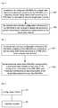
- Fig. 4 is a flowchart showing an interference measurement method according to an embodiment of the disclosure, and as shown in Fig. 4 , the method includes the following steps.
- Step 401 a network side configures DM-IMRs for a target data channel of a terminal, positions of the DM-IMRs on a frequency domain being determined according to a PRB which is allocated to bear the target data channel;
- Step 402 the network side indicates configuration information of the DM-IMRs to the terminal to enable the terminal to perform transmission interference measurement on the target data channel.
- the positions of the DM-IMRs on the frequency domain only exist in the PRB which bears the target data channel.
- the DM-IMRs include one of the following resources:
- the DM-IMRs are the RE resources configured as ZP-CSI-RSs
- the DM-IMRs are one or more sets of RE resources configured as ZP-CSI-RS resources; or the DM-IMRs are a part of RE resources in one or more sets of RE resources configured as ZP-CSI-RS resources.
- the DM-IMRs are the RE resources configured as CSI-RSs
- the DM-IMRs are one or more sets of RE resources configured as single-antenna or double-antenna port CSI-RS resources; or the DM-IMRs are one or more sets of RE resources configured as four-antenna port CSI-RS resources; or the DM-IMRs are one or more sets of RE resources configured as eight-antenna port CSI-RS resources.
- the DM-IMRs are the RE resources configurable as CRSs
- the DM-IMRs are RE resources at a position where a serving cell CRS of the terminal is located; or the DM-IMRs are a part of RE resources at the position where the serving cell CRS of the terminal is located; or the DM-IMRs are RE resources at a position where an interference cell CRS of the terminal is located; or the DM-IMRs are a part of RE resources at the position where the interference cell CRS of the terminal is located.
- the RE resources configurable as ZP-CSI-RSs are RE resources which are supported by a communication system and may be configured as ZP-CSI-RSs or RE resources which are added on the basis of the RE resources which are supported by the communication system and may be configured as ZP-CSI-RSs and may be configured into ZP-CSI-RSs; and the RE resources configurable as CSI-RSs are RE resources which are supported by the communication system and may be configured as CSI-RSs or RE resources configurable as CSI-RSs which are added on the basis of the RE resources which are supported by the communication system and may be configured as CSI-RSs.
- the RE resources which may be configured into ZP-CSI-RSs are determined by CSI-RS configurations which may be configured into ZP-CSI-RS resources; or the RE resources which may be configured into ZP-CSI-RSs are determined by both the CSI-RS configurations which may be configured into ZP-CSI-RSs and CSI-RS sub-frame configurations which may be configured into ZP-CSI-RS resources.
- the RE resources which may be configured into CSI-RSs are determined by CSI-RS configurations which may be configured into CSI-RS resources; or the RE resources which may be configured into CSI-RSs are determined by both the CSI-RS configurations which may be configured into CSI-RS resources and CSI-RS sub-frame configurations which may be configured into CSI-RS resources.
- an attribute of the DM-IMRs is that: the network side sends zero power signals on the DM-IMRs, and the target data channel is mapped to the DM-IMRs in a rate matching manner.
- the DM-IMRs only exist in a sub-frame which bears the target data channel.
- the DM-IMRs are not configured in a sub-frame where a PMCH is located.
- the part of RE resources at the position where the CRS is located are located in an RE resource area of transmission of the target data channel.
- the configuration information of the DM-IMRs is indicated to the terminal in one of manners as follows:
- a DM-IMR Information Element (IE) configuration item is set in the high-layer signalling, and the DM-IMR IE configuration item includes one or more of:
- the DM-IMR configuration includes at least one of:
- the DM-IMR sub-frame configuration includes at least one of:
- a representation manner for the DM-IMR configuration includes one of manners as follows:
- the operation that the multiple sets of DM-IMRs are configured through the high-layer signalling and the DM-IMRs configured for the interference measurement of the current target data channel therein are indicated to the terminal through physical-layer dynamic signalling includes:
- the technical solution of the disclosure is applicable to multiple LTE systems in LTE R11 as well as LTE R10 and the like.
- the embodiment of the disclosure also correspondingly discloses an interference measurement method, and as shown in Fig. 5 , the method includes:
- the positions of the DM-IMRs on the frequency domain only exist in the PRB which bears the target data channel.
- the DM-IMRs include one of the following resources:
- the DM-IMRs are the RE resources which may be configured into ZP-CSI-RSs
- the DM-IMRs are one or more sets of RE resources which may be configured into ZP-CSI-RS resources; or the DM-IMRs are a part of RE resources in one or more sets of RE resources which may be configured into ZP-CSI-RS resources.
- the DM-IMRs are the RE resources which may be configured into CSI-RSs
- the DM-IMRs are one or more sets of RE resources which may be configured into single-antenna or double-antenna port CSI-RS resources; or the DM-IMRs are one or more sets of RE resources which may be configured into four-antenna port CSI-RS resources; or the DM-IMRs are one or more sets of RE resources which may be configured into eight-antenna port CSI-RS resources.
- the DM-IMRs are the RE resources which may be configured into CRSs
- the DM-IMRs are RE resources at a position where a serving cell CRS of the terminal is located; or the DM-IMRs are a part of RE resources at the position where the serving cell CRS of the terminal is located; or the DM-IMRs are RE resources at a position where an interference cell CRS of the terminal is located; or the DM-IMRs are a part of RE resources at the position where the interference cell CRS of the terminal is located.
- the RE resources which may be configured into ZP-CSI-RSs are RE resources which are supported by a communication system and may be configured into ZP-CSI-RSs or RE resources which are added on the basis of the RE resources which are supported by the communication system and may be configured into ZP-CSI-RSs and may be configured into ZP-CSI-RSs; and the RE resources which may be configured into CSI-RSs are RE resources which are supported by the communication system and may be configured into CSI-RSs or RE resources which are added on the basis of the RE resources which are supported by the communication system and may be configured into CSI-RSs and may be configured into CSI-RSs.
- the RE resources which may be configured into ZP-CSI-RSs are determined by CSI-RS configurations which may be configured into ZP-CSI-RS resources; and the RE resources which may be configured into CSI-RSs are determined by CSI-RS configurations which may be configured into CSI-RS resources.
- the RE resources which may be configured into ZP-CSI-RSs are determined by both the CSI-RS configurations which may be configured into ZP-CSI-RSs and CSI-RS sub-frame configurations which may be configured into ZP-CSI-RS resources; and the RE resources which may be configured into CSI-RSs are determined by both the CSI-RS configurations which may be configured into CSI-RS resources and CSI-RS sub-frame configurations which may be configured into CSI-RS resources.
- the terminal does not receive any signal on the DM-IMRs, and de-maps the target data channel on the DM-IMRs in a rate matching manner.
- the terminal determines as a default that the DM-IMRs only exist in a sub-frame which bears the target data channel.
- the terminal determines as a default that there are no DM-IMRs in a sub-frame where a PMCH is located.
- the terminal determines as a default that the part of RE resources at the position where the CRS is located are located in an RE resource area of transmission of the target data channel.
- the terminal receives the configuration information of the DM-IMRs in one of manners of:
- the terminal determines the configured DM-IMRs by receiving a DM-IMR IE configuration item in the high-layer signalling, and the DM-IMR IE configuration item includes one or more of:
- the DM-IMR configuration includes at least one of:
- the DM-IMR sub-frame configuration includes at least one of:
- a representation manner for the DM-IMR configuration includes one of manners as follows:
- the terminal specifically determines N sets of available DM-IMRs by receiving the high-layer signalling, and determines resources configured for the interference measurement of the current target data channel by receiving
- the embodiment of the disclosure also correspondingly discloses network-side equipment, and as shown in Fig. 6 , the network-side equipment includes: a configuration module 61 and an indication module 62, wherein the configuration module 61 is configured to configure DM-IMRs to a target data channel of a terminal, positions of the DM-IMRs on the frequency domain being determined according to a PRB which bears the target data channel; and the indication module 62 is configured to indicate configuration information of the DM-IMRs configured by the configuration module 61 to the terminal to enable the terminal to perform transmission interference measurement on the target data channel.
- the configuration module 61 is configured to configure DM-IMRs to a target data channel of a terminal, positions of the DM-IMRs on the frequency domain being determined according to a PRB which bears the target data channel
- the indication module 62 is configured to indicate configuration information of the DM-IMRs configured by the configuration module 61 to the terminal to enable the terminal to perform transmission interference measurement on the target data channel.
- the positions of the DM-IMRs on the frequency domain only exist in the PRB which bears the target data channel.
- the DM-IMRs include one of the following resources:
- the DM-IMRs are the RE resources which may be configured into ZP-CSI-RSs
- the DM-IMRs are one or more sets of RE resources which may be configured into ZP-CSI-RS resources; or the DM-IMRs are a part of RE resources in one or more sets of RE resources which may be configured into ZP-CSI-RS resources.
- the DM-IMRs are the RE resources which may be configured into CSI-RSs
- the DM-IMRs are one or more sets of RE resources which may be configured into single-antenna or double-antenna port CSI-RS resources; or the DM-IMRs are one or more sets of RE resources which may be configured into four-antenna port CSI-RS resources; or the DM-IMRs are one or more sets of RE resources which may be configured into eight-antenna port CSI-RS resources.
- the DM-IMRs are the RE resources which may be configured into CRSs
- the DM-IMRs are RE resources at a position where a serving cell CRS of the terminal is located; or the DM-IMRs are a part of RE resources at the position where the serving cell CRS of the terminal is located; or the DM-IMRs are RE resources at a position where an interference cell CRS of the terminal is located; or the DM-IMRs are a part of RE resources at the position where the interference cell CRS of the terminal is located.
- the RE resources which may be configured into ZP-CSI-RSs are RE resources which are supported by a communication system and may be configured into ZP-CSI-RSs or RE resources which are added on the basis of the RE resources which are supported by the communication system and may be configured into ZP-CSI-RSs and may be configured into ZP-CSI-RSs; and the RE resources which may be configured into CSI-RSs are RE resources which are supported by the communication system and may be configured into CSI-RSs or RE resources which are added on the basis of the RE resources which are supported by the communication system and may be configured into CSI-RSs and may be configured into CSI-RSs.
- the RE resources which may be configured into ZP-CSI-RSs are determined by CSI-RS configurations which may be configured into ZP-CSI-RS resources; and the RE resources which may be configured into CSI-RSs are determined by CSI-RS configurations which may be configured into CSI-RS resources.
- the RE resources which may be configured into ZP-CSI-RSs are determined by both the CSI-RS configurations which may be configured into ZP-CSI-RSs and CSI-RS sub-frame configurations which may be configured into ZP-CSI-RS resources; and the RE resources which may be configured into CSI-RSs are determined by both the CSI-RS configurations which may be configured into CSI-RS resources and CSI-RS sub-frame configurations which may be configured into CSI-RS resources.
- an attribute of the DM-IMRs is that: a network side sends zero power signals on the DM-IMRs, and the target data channel is mapped to the DM-IMRs in a rate matching manner.
- configuration module is further configured to configure that the DM-IMRs only exist in a sub-frame which bears the target data channel.
- the configuration module is further configured not to configure the DM-IMRs in a sub-frame where a PMCH is located.
- the part of RE resources at the position where the CRS is located are located in an RE resource area of transmission of the target data channel.
- the indication module indicates the configuration information of the DM-IMRs configured to the target data channel of the terminal to the terminal in one of manners of:
- a DM-IMR IE configuration item is set in the high-layer signalling, and the DM-IMR IE configuration item includes one or more of:
- the DM-IMR configuration includes at least one of:
- the DM-IMR sub-frame configuration includes at least one of:
- a representation manner for the DM-IMR configuration includes one of manners as follows:
- the indication module 62 is further configured to configure N sets of DM-IMRs to the terminal through high-layer signalling, and indicate DM-IMRs configured for the interference measurement of the current target data channel therein to the terminal through
- the terminal equipment includes: a receiving module 71 and a measurement module 72, wherein the receiving module 71 is configured to receive configuration information of DM-IMRs, positions of the DM-IMRs on the frequency domain being determined according to a PRB which bears a target data channel; and the measurement module 72 is configured to determine DM-IMRs corresponding to the target data channel according to the configuration information of the DM-IMRs, and measure interference during transmission of the target data channel through the DM-IMRs.
- the receiving module 71 is configured to receive configuration information of DM-IMRs, positions of the DM-IMRs on the frequency domain being determined according to a PRB which bears a target data channel
- the measurement module 72 is configured to determine DM-IMRs corresponding to the target data channel according to the configuration information of the DM-IMRs, and measure interference during transmission of the target data channel through the DM-IMRs.
- the positions of the DM-IMRs on the frequency domain only exist in the PRB which bears the target data channel.
- the DM-IMRs include one of the following resources:
- the DM-IMRs are the RE resources which may be configured into ZP-CSI-RSs
- the DM-IMRs are one or more sets of RE resources which may be configured into ZP-CSI-RS resources; or the DM-IMRs are a part of RE resources in one or more sets of RE resources which may be configured into ZP-CSI-RS resources.
- the DM-IMRs are the RE resources which may be configured into CSI-RSs
- the DM-IMRs are one or more sets of RE resources which may be configured into single-antenna or double-antenna port CSI-RS resources; or the DM-IMRs are one or more sets of RE resources which may be configured into four-antenna port CSI-RS resources; or the DM-IMRs are one or more sets of RE resources which may be configured into eight-antenna port CSI-RS resources.
- the DM-IMRs are the RE resources which may be configured into CRSs
- the DM-IMRs are RE resources at a position where a serving cell CRS of the terminal is located; or the DM-IMRs are a part of RE resources at the position where the serving cell CRS of the terminal is located; or the DM-IMRs are RE resources at a position where an interference cell CRS of the terminal is located; or the DM-IMRs are a part of RE resources at the position where the interference cell CRS of the terminal is located.
- the RE resources which may be configured into ZP-CSI-RSs are RE resources which are supported by a communication system and may be configured into ZP-CSI-RSs or RE resources which are added on the basis of the RE resources which are supported by the communication system and may be configured into ZP-CSI-RSs and may be configured into ZP-CSI-RSs; and the RE resources which may be configured into CSI-RSs are RE resources which are supported by the communication system and may be configured into CSI-RSs or RE resources which are added on the basis of the RE resources which are supported by the communication system and may be configured into CSI-RSs and may be configured into CSI-RSs.
- the RE resources which may be configured into ZP-CSI-RSs are determined by CSI-RS configurations which may be configured into ZP-CSI-RS resources; and the RE resources which may be configured into CSI-RSs are determined by CSI-RS configurations which may be configured into CSI-RS resources.
- the RE resources which may be configured into ZP-CSI-RSs are determined by both the CSI-RS configurations which may be configured into ZP-CSI-RSs and CSI-RS sub-frame configurations which may be configured into ZP-CSI-RS resources; and the RE resources which may be configured into CSI-RSs are determined by both the CSI-RS configurations which may be configured into CSI-RS resources and CSI-RS sub-frame configurations which may be configured into CSI-RS resources.
- the receiving module is further configured to not receive any signal on the DM-IMRs, and de-map the target data channel on the DM-IMRs in a rate matching manner.
- the receiving module is further configured to determine as a default that the DM-IMRs only exist in a sub-frame which bears the target data channel.
- the receiving module is further configured to determine as a default that there are no DM-IMRs in a sub-frame where a PMCH is located.
- the receiving module is further configured to determine as a default that the part of RE resources at the position where the CRS is located are located in an RE resource area of transmission of the target data channel.
- the receiving module is further configured to receive the configuration information of the DM-IMRs in one of manners of:
- the receiving module is further configured to determine the configured DM-IMRs by receiving a DM-IMR IE configuration item in the high-layer signalling, and the DM-IMR IE configuration item includes one or more of:
- the DM-IMR configuration includes at least one of:
- the DM-IMR sub-frame configuration includes at least one of:
- a representation manner for the DM-IMR configuration includes one of manners as follows:
- the measurement module 72 further determines N sets of available DM-IMRs by receiving the high-layer signalling, and determines resources configured for the interference measurement of the current target data channel by receiving
- the embodiment of the disclosure also correspondingly discloses an interference measurement system, which includes the abovementioned network-side equipment and the above-mentioned terminal equipment.
- the embodiment provides an interference measurement method, which mainly includes:
- positions of the DM-IMRs on the frequency domain are determined according to a PRB which bears the target data channel.
- the DM-IMRs are only allowed to exist in a PRB resource where the target data channel of the terminal is located, that is, a PRB resource where the DM-IMRs of the target terminal is located is the same as the PRB resource where the target data channel is located.
- the target data channel mentioned here is a channel that the terminal is required to receive currently and the target data channel includes at least one of a PDSCH, an ePDCCH and a PDCCH.
- the embodiment includes the following steps.
- Step 1 the network side configures the DM-IMRs for the terminal, wherein the DM-IMRs may be at least one of the following resources.
- the network side sends zero power signals on the DM-IMRs, and at the same time the target data channel is mapped to the DM-IMRs in the rate matching manner.
- the DM-IMRs exist and only exist in a sub-frame which bears the target data channel. That is, sending of the DM-IMRs is triggered by transmission of the target data channel, and the DM-IMRs corresponding to the target data channel do not exist once the transmission of the target data channel is stopped.
- no DM-IMRs are configured in a sub-frame where a PMCH is located.
- the part of RE resources in the resources at the position where the CRS is located are configured for DM-IMRs
- the part of RE resources are usually located in the RE resource area which bears the target data channel.
- Step 2 the network side indicates the configuration information of the DM-IMRs to the terminal, wherein the network side may notify the terminal of the configuration information of the DM-IMRs in one of manners of:
- the high-layer signalling preferably refers to Radio Resource Control (RRC) signalling
- RRC Radio Resource Control
- the physical-layer signalling refers to uplink and/or downlink signalling of a PDCCH or an ePDCCH.
- the network side adds a DM-IMR IE configuration item which is configured to indicate a condition of resource configuration in each set of DM-IMRs in the high-layer signalling, wherein the IE configuration item at least includes one of:
- the DM-IMR configuration includes at least one of:
- the DM-IMR sub-frame configuration includes at least one of:
- the CSI-RS sub-frame configuration supported in LTE R11 is shown in Table 4: Table 4 CSI-RS sub-frame configuration I CSI-RS CSI-RS period T CSI-RS (sub-frame) CSI-RS sub-frame offset ⁇ CSI-RS (sub-frame) 0-4 5 I CSI-RS 5-14 10 I CSI-RS -5 15-34 20 I CSI-RS -15 35-74 40 I CSI-RS -35 75-154 80 I CSI-RS -75
- the CSI-RS sub-frame configuration enhanced on the basis of LTE R11 is shown in Table 5: Table 5 CSI-RS sub-frame configuration I CSI-RS CSI-RS period T CSI-RS (sub-frame) CSI-RS sub-frame configuration ⁇ CSI-RS (sub-frame) 0-4 5 I CSI-RS 5-14 10 I CSI-RS -5 15-34 20 I CSI-RS -15 35-74 40 I CSI-RS -35 75-154 80 I CSI-RS -75 155 1 0 156-157 2 I CSI-RS -156 158-160 3 I CSI-RS -158 160-163 4 I CSI-RS -160
- the DM-IMR configuration may be characterized in one of manners as follows:
- the network side configures N sets of DM-IMRs through high-layer signalling, and the network side indicates which set or sets in the N sets of DM-IMRs are configured as the DM-IMRs of the current target data channel to the terminal through
- each set of DM-IMRs preferably has a different DM-IMR ID from the other N-1 sets of DM-IMRs.
- Step 3 the terminal receives the configuration information of the DM-IMRs through the high-layer signalling and/or the physical-layer signalling, determines the DM-IMRs of the target data channel, and measures the interference during the transmission of the target data channel through the DM-IMRs.
- the terminal performs interference elimination/suppression at a receiver on the basis of the measured interference to achieve higher target data channel receiving performance.
- the terminal does not receive any signal on the DM-IMRs, and de-maps the target data channel on the DM-IMRs in the rate matching manner.
- the terminal only monitors the DM-IMRs in the PRB and sub-frame which bear the target data channel.
- a network side configures DM-IMRs for a terminal, wherein REs configured as the DM-IMRs are REs corresponding to ZP-CSI-RSs.
- the DM-IMRs configured for the terminal by the network side consist of one or more ZP-CSI-RS resources.
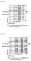
- Fig. 8(a) / Fig. 8(b) show all REs which may be configured as ZP-CSI-RSs in a sub-frame in a system under a normal CP condition, wherein each sequence number represents resource which may be configured as ZP-CSI-RS.
- Fig. 9(a) / Fig. 9(b) show all RE resources which may be configured as ZP-CSI-RSs in a sub-frame in the system under an extended CP condition, wherein each sequence number represents resource which may be configured as ZP-CSI-RS.
- the network side indicates the DM-IMRs to the terminal in one of the two manners as follows.
- the network side only performs puncturing or rate matching on REs of the DM-IMRs configured for the user on a bandwidth which bears the target data channel.
- the network side only performs puncturing or rate matching on the REs of the DM-IMRs configured for the user on a sub-frame which bears the target data channel.
- a target user receives information of the DM-IMRs configured by the network side; and a User Equipment (UE) side performs data de-mapping in the same manner as that adopted by the network side on the sub-frame which bears the target data channel: if the network side performs rate matching on the REs of the DM-IMRs configured for the user, the UE side determines as a default that the REs for transmitting the DM-IMRs do not have any data corresponding to the target data channel, and if the network side performs puncturing on the REs of the DM-IMRs configured for the user, the UE side determines that signals received on these REs are still data of the target data channel of the user.
- UE User Equipment
- the target user determines the number of the ZP-CSI-RSs configured for demodulation interference measurement by the network side and RE resource positions corresponding to each ZP-CSI-RS according to the information of the DM-IMRs configured by the network side.
- the target user estimates interference by means of the RE resource position corresponding to each ZP-CSI-RS respectively.
- the target user performs interference compression or interference elimination processing on the basis of each piece of estimated interference information by adopting a receiving detection algorithm, and detects data information of the target data channel.
- a network side configures DM-IMRs for a terminal, wherein REs configured into the DM-IMRs are REs corresponding to ZP-CSI-RSs. Specifically, the network side configures one or more sets of DM-IMRs for the terminal, wherein each set of DM-IMRs consists of one or more ZP-CSI-RS resources.
- Fig. 8(a) / Fig. 8(b) show all REs which may be configured into ZP-CSI-RSs in a sub-frame in a system under a normal CP condition, wherein each sequence number represents resource which may be configured into ZP-CSI-RS.
- Fig. 9(a) / Fig. 9(b) show all RE resources which may be configured as ZP-CSI-RSs in a sub-frame in the system under an extended CP condition, wherein each sequence number represents resource which may be configured as ZP-CSI-RS.
- the network side indicates the DM-IMRs to the terminal in one of the following manners.
- the network side only performs puncturing or rate matching on REs of the DM-IMRs configured for the user on a bandwidth which bears the target data channel.
- the network side only performs puncturing or rate matching on the REs of the DM-IMRs configured for the user on a sub-frame which bears the target data channel.
- a target user receives information of the DM-IMRs configured by the network side; and a UE side performs data de-mapping in the same manner as that adopted by the network side on the sub-frame which bears the target data channel: if the network side performs rate matching on the REs of the DM-IMRs configured for the user, the UE side determines as a default that the REs for transmitting the DM-IMRs do not have any data corresponding to the target data channel, and if the network side performs puncturing on the REs of the DM-IMRs configured for the user, the UE side determines that signals received on these REs are still data of the target data channel of the user.
- the target user determines the number of the DM-IMRs configured by the network side and RE resource positions corresponding to the ZP-CSI-RSs in each set of DM-IMRs according to the information of the DM-IMRs configured by the network side.
- the target user estimates interference by means of the RE resource positions corresponding to each set of DM-IMRs respectively.
- the target user performs interference compression or interference elimination processing on the basis of each piece of estimated interference information by adopting a receiving detection algorithm, and detects data information of the target data channel.
- a network side configures DM-IMRs for a terminal, wherein REs configured as the DM-IMRs are REs corresponding to ZP-CSI-RSs. Specifically, the network side configures one or more sets of DM-IMRs for the terminal, wherein each set of DM-IMRs consists of one or more ZP-CSI-RS resources and each ZP-CSI-RS resource corresponds to a CSI-RS sub-frame configuration.
- Fig. 8(a) / 8(b) shows all REs which may be configured as ZP-CSI-RSs in a sub-frame in a system under a normal CP condition, wherein each sequence number represents resource which may be configured as ZP-CSI-RS.
- the CSI-RS sub-frame configuration is a CSI-RS sub-frame configuration supported in LTE R11, as shown in Table 2, wherein each sub-frame configuration corresponds to a CSI-RS period and a CSI-RS sub-frame offset or a CSI-RS sub-frame configuration which is added by the network side on the basis of the CSI-RS sub-frame configuration supported in LTE R11, the CSI-RS sub-frame configuration has a shorter CSI-RS period than the CSI-RS sub-frame configuration supported in LTE R11, and the added CSI-RS sub-frame configuration preferably supports the condition that the CSI-RS period is 1, for example, as shown in Table 3.
- the network side notifies the terminal of the one or more sets of DM-IMRs through high-layer signalling. Specifically, the network side adds a DM-IMR IE configuration item which is configured to indicate a condition of resource configuration in each set of DM-IMRs in the high-layer signalling, wherein the IE configuration item includes:
- the network side only performs puncturing or rate matching on REs of the DM-IMRs configured for the user on a bandwidth which bears a target data channel.
- the network side only performs puncturing or rate matching on the REs of the DM-IMRs configured for the user on a sub-frame which bears the target data channel.
- a target user receives information of the DM-IMRs configured by the network side; and a UE side performs data de-mapping in the same manner as that adopted by the network side on the sub-frame which bears the target data channel: if the network side performs rate matching on the REs of the DM-IMRs configured for the user, the UE side determines as a default that the REs for transmitting the DM-IMRs do not have any data corresponding to the target data channel, and if the network side performs puncturing on the REs of the DM-IMRs configured for the user, the UE side determines that signals received on these REs are still data of the target data channel of the user.
- the target user determines the number of the DM-IMRs configured by the network side and RE resource positions corresponding to the ZP-CSI-RSs in each set of DM-IMRs according to the information of the DM-IMRs configured by the network side.
- the target user estimates interference by means of the RE resource positions corresponding to each set of DM-IMRs respectively.
- the target user performs interference compression or interference elimination processing on the basis of each piece of estimated interference information by adopting a receiving detection algorithm, and detects data information of the target data channel.
- a network side configures DM-IMRs for a terminal, wherein REs configured as the DM-IMRs are REs corresponding to ZP-CSI-RS resources which are added by the network side on the basis of a ZP-CSI-RS resource configuration supported in LTE R11.
- the DM-IMRs configured for the terminal by the network side include one or more ZP-CSI-RS resources.
- Fig. 8(a) / 8(b) shows all REs which may be configured as ZP-CSI-RSs supported in LTE R11 in a sub-frame in a system under a normal CP condition, wherein each sequence number represents a resource which may be configured into a ZP-CSI-RS.
- the ZP-CSI-RS resources mentioned here also include the ZP-CSI-RS resources which will be added on the basis of the ZP-CSI-RS resource configurations supported in LTE R11 in the future, and for example, a PDCCH area is removed in a new carrier type, which may allow addition of new ZP-CSI-RS resources in the PDCCH area in the new carrier type.
- the network side indicates the DM-IMRs to the terminal in one of manners as follows.
- the network side only performs puncturing or rate matching on REs of the DM-IMRs configured for the user on a bandwidth which bears the target data channel.
- the network side only performs puncturing or rate matching on the REs of the DM-IMRs configured for the user on a sub-frame which bears the target data channel.
- a target user receives information of the DM-IMRs configured by the network side; and a UE side performs data de-mapping in the same manner as that adopted by the network side on the sub-frame which bears the target data channel: if the network side performs rate matching on the REs of the DM-IMRs configured to the user, the UE side determines as a default that the REs for transmitting the DM-IMRs do not have any data corresponding to the target data channel, and if the network side performs puncturing on the REs of the DM-IMRs configured to the user, the UE side determines that signals received on these REs are still data of the target data channel of the user.
- the target user determines the number of the DM-IMRs or ZP-CSI-RSs configured by the network side and RE resource positions corresponding to each set of DM-IMRs or each ZP-CSI-RS according to the information of the DM-IMRs configured by the network side.
- the target user estimates interference by means of the RE resource positions corresponding to each set of DM-IMRs or each ZP-CSI-RS respectively.
- the target user performs interference compression or interference elimination processing on the basis of each piece of estimated interference information by adopting a receiving detection algorithm, and detects data information of the target data channel.
- a network side configures DM-IMRs for a terminal, wherein REs configured into the DM-IMRs are REs corresponding to a part of REs in REs corresponding to ZP-CSI-RS resources, and the other part of REs may serve as DM-IMRs of another terminal or may still be configured to transmit ZI-CSI-RSs.
- the DM-IMRs configured to the terminal by the network side include one or more ZP-CSI-RS resources.
- FIG. 8(a) / 8(b) shows all REs which may be configured into ZP-CSI-RSs supported in LTE R11 in a sub-frame in a system under a normal CP condition, wherein each sequence number represents a resource which may be configured into a ZP-CSI-RS.
- Fig. 9(a) / 9(b) shows all RE resources which may be configured into ZP-CSI-RSs supported in LTE R11 in a sub-frame in the system under an extended CP condition, wherein each sequence number represents a resource which may be configured as a ZP-CSI-RS.
- the ZP-CSI-RS resources mentioned here also include ZP-CSI-RS resources which will be added on the basis of a ZP-CSI-RS resource configuration supported in LTE R11 in the future, and for example, a PDCCH area is removed in a new carrier type, which may allow addition of new ZP-CSI-RS resources in the PDCCH area in the new carrier type.
- the network side indicates the DM-IMRs to the terminal in one of manners as follows.
- the network side only performs puncturing or rate matching on REs of the DM-IMRs configured to the user on a bandwidth, which bears the target data channel, of the user.
- the network side only performs puncturing or rate matching on the REs of the DM-IMRs configured to the user on a sub-frame, which bears the target data channel, of the user.
- a target user receives information of the DM-IMRs configured by the network side; and a UE side performs data de-mapping in a manner the same as that adopted by the network side on the sub-frame which bears the target data channel: if the network side performs rate matching on the REs of the DM-IMRs configured to the user, the UE side determines as a default that the REs for transmitting the DM-IMRs do not have any data corresponding to the target data channel, and if the network side performs puncturing on the REs of the DM-IMRs configured to the user, the UE side determines that signals received on these REs are still data of the target data channel of the user.
- the target user determines the number of the DM-IMRs or ZP-CSI-RSs configured by the network side and RE resource positions corresponding to each set of DM-IMRs or each ZP-CSI-RS according to the information of the DM-IMRs configured by the network side.
- the target user estimates interference by virtue of the RE resource positions corresponding to each set of DM-IMRs or each ZP-CSI-RS respectively.
- the target user performs interference compression or interference elimination processing on the basis of each piece of estimated interference information by adopting a receiving detection algorithm, and detects data information of the target data channel.
- a network side configures DM-IMRs for a terminal, wherein REs configured into the DM-IMRs are double-antenna port CSI-RS resources supported in LTE R11 or REs corresponding to double-antenna port CSI-RS resources which are added by the network side on the basis of a double-antenna port CSI-RS resource configuration supported in LTE R11.
- the DM-IMRs configured to the terminal by the network side include one or more double-antenna port CSI-RS resources.
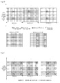
- 10(a) / 10(b) shows all REs which may be configured into double-antenna port CSI-RSs supported in LTE R11 in a sub-frame in a system under a normal CP condition, wherein each sequence number represents a resource which may be configured into a double-antenna port CSI-RS.
- Fig. 11 (a)/11 (b) shows all RE resources which may be configured into double-antenna port CSI-RSs supported in LTE R11 in a sub-frame in the system under an extended CP condition, wherein each sequence number represents a resource which may be configured into a double-antenna port CSI-RS.
- the double-antenna port CSI-RS resources mentioned here also include the double-antenna port CSI-RS resources which will be added on the basis of the double-antenna port CSI-RS resource configuration supported in LTE R11 in the future, and for example, a PDCCH area is removed in a new carrier type, which may cause addition of new double-antenna port CSI-RS resources in the PDCCH area in the new carrier type.
- the network side indicates the DM-IMRs to the terminal in one of manners as follows.
- the network side only performs puncturing or rate matching on REs of the DM-IMRs configured to the user on a bandwidth, which bears the target data channel, of the user.
- the network side only performs puncturing or rate matching on the REs of the DM-IMRs configured to the user on a sub-frame, which bears the target data channel, of the user.
- a target user receives information of the DM-IMRs configured by the network side; and a UE side performs data de-mapping in a manner the same as that adopted by the network side on the sub-frame which bears the target data channel: if the network side performs rate matching on the REs of the DM-IMRs configured to the user, the UE side determines as a default that the REs for transmitting the DM-IMRs do not have any data corresponding to the target data channel, and if the network side performs puncturing on the REs of the DM-IMRs configured to the user, the UE side determines that signals received on these REs are still data of the target data channel of the user.
- the target user determines the number of the DM-IMRs or double-antenna port CSI-RSs configured by the network side and RE resource positions corresponding to each set of DM-IMRs or each double-antenna port CSl-RS according to the information of the DM-IMRs configured by the network side.
- the target user estimates interference by virtue of the RE resource positions corresponding to each set of DM-IMRs or each double-antenna port CSl-RS respectively.
- the target user performs interference compression or interference elimination processing on the basis of each piece of estimated interference information by adopting a receiving detection algorithm, and detects data information of the target data channel.
- a network side configures DM-IMRs for a terminal, wherein REs configured into the DM-IMRs are RE resources at a position of a serving cell CRS is located or a part of RE resources at the position where the serving cell CRS is located or RE resources at a position where an interference cell CRS is located or a part of RE resources at the position where the interference cell CRS is located.
- REs configured into the DM-IMRs are RE resources at a position of a serving cell CRS is located or a part of RE resources at the position where the serving cell CRS is located or RE resources at a position where an interference cell CRS is located or a part of RE resources at the position where the interference cell CRS is located.
- FIGS. 17 are diagrams of a CRS resource under a normal CP condition and an extended CP condition according to the existing technology respectively, wherein R 0 represents an RE resource occupied by a CRS antenna port 0, R 1 represents an RE resource occupied by a CRS antenna port 1, R 2 represents an RE resource occupied by a CRS antenna port 2 and R 3 represents an RE resource occupied by a CRS antenna port 3.
- the network side indicates the DM-IMRs to the terminal in one of manners as follows.
- the network side only performs puncturing or rate matching on REs of the DM-IMRs configured for the user on a bandwidth, which bears the target data channel, of the user.
- the network side only performs puncturing or rate matching on the REs of the DM-IMRs configured for the user on a sub-frame, which bears the target data channel, of the user.
- a target user receives information of the DM-IMRs configured by the network side; and a UE side performs data de-mapping in a manner the same as that adopted by the network side on the sub-frame which bears the target data channel: if the network side performs rate matching on the REs of the DM-IMRs configured to the user, the UE side determines as a default that the REs for transmitting the DM-IMRs do not have any data corresponding to the target data channel, and if the network side performs puncturing on the REs of the DM-IMRs configured to the user, the UE side determines that signals received on these REs are still data of the target data channel of the user.
- the target user determines the DM-IMRs configured by the network side and the RE resource positions corresponding to each set of DM-IMRs according to the information of the DM-IMRs configured by the network side.
- the target user estimates interference by virtue of the RE resource positions corresponding to each set of DM-IMRs respectively.
- the target user performs interference compression or interference elimination processing on the basis of each piece of estimated interference information by adopting a receiving detection algorithm, and detects data information of the target data channel.
- a specific IMR configuration method and interference measurement manner include:
- Information of the DM-IMRs configured by the network side at least includes information of ZP-CSI-RSs configured into the DM-IMRs.
- a specific configuration manner includes:
- the network side only performs puncturing or rate matching on REs of the DM-IMRs configured to the user on a bandwidth, which bears the target data channel, of the user.
- the network side only performs puncturing or rate matching on the REs of the DM-IMRs configured to the user on a sub-frame, which bears the target data channel, of the user.
- UE receives the information of the DM-IMRs configured by the network side; and a UE side performs data de-mapping in a manner the same as that adopted by the network side on the sub-frame which bears the target data channel: if the network side performs rate matching on the REs of the DM-IMRs configured to the user, the UE side determines as a default that the REs for transmitting the DM-IMRs do not have any data corresponding to the target data channel, and if the network side performs puncturing on the REs of the DM-IMRs configured to the user, the UE side determines that signals received on these REs are still data of the target data channel of the user.
- the target user determines the number of the ZP-CSI-RSs configured into the DM-IMRs configured by the network side and RE resource positions corresponding to each ZP-CSI-RS according to the information of the DM-IMRs configured by the network side.
- the target user estimates interference by virtue of the RE resource positions corresponding to each ZP-CSI-RS respectively.
- the target user performs interference compression or interference elimination processing on the basis of each piece of estimated interference information by adopting a receiving detection algorithm, and detects data information of the target data channel.
- DM-IMRs configured for a target user by a network side are one or more ZP-CSI-RS resources, and ZP-CSI-RS resource indexes or resource configuration or resource positions of the DM-IMRs are notified to the target user through high-layer signalling and/or physical-layer signalling.
- the DM-IMRs exist and only exist in a PRB and sub-frame which bear a target data channel.
- the network side configures a ZP-CSI-RS resource to the target user, an ZP-CSI-RS resource index (or resource configuration) being 0, and the network side notifies the DM-IMR to the target user through high-layer signalling and/or physical-layer signalling.
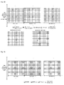
- the DM-IMRs are configured as shown in Fig. 18 : the
- DM-IMRs " exist and only exist in each sub-frame and each PRB of resources where a PDSCH/ePDCCH of the target user is located, and four REs exist in each PRB (corresponding to a ZP-CSI-RS resource configuration, the ZP-CSI-RS resource configuration being 0 in the embodiment); the target user sends zero power signals on the DM-IMRs, and the target user performs PDSCH/ePDCCH mapping on these DM-IMRs in a rate matching manner; and therefore, signals received on the DM-IMRs are correspondingly interference signals of the target user on each sub-frame and each PRB.
- the target user performs interference elimination or interference suppression on a receiving side to achieve higher PDSCH or ePDCCH demodulation/decoding performance by means of the interference signals measured on the DM-IMRs.
- DM-IMRs configured for a target user by a network side are one or more ZP-CSI-RS resources, and ZP-CSI-RS indexes (or resource configuration or resource positions) in the DM-IMRs and a corresponding CSl-RS sub-frame configuration are notified to the target user through high-layer signalling and/or physical-layer signalling.
- the DM-IMRs exist and only exist in a PRB which bears a target data channel on the frequency domain
- the CSl-RS sub-frame configuration is configured to determine a sub-frame where the DM-IMRs are located on the time domain.
- the network side configures M sets of ZP-CSI-RS resources for the target user, including:
- each sub-frame has the ZP-CSI-RS resource configuration n0 available for the DM-IMRs of the target user.
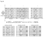
- the DM-IMRs are configured as shown in Fig. 18 : the DM-IMRs " " exist and only exist in each sub-frame and each PRB of resources where a PDSCH/ePDCCH of the target user is located, and four REs exist in each PRB (corresponding to a ZP-CSI-RS resource configuration, the ZP-CSI-RS resource configuration being 0 in the embodiment); the target user sends zero power signals on the DM-IMRs, and the target user performs PDSCH/ePDCCH mapping on these DM-IMRs in a rate matching manner; and therefore, signals received on the DM-IMRs are correspondingly interference signals of the target user on each sub-frame and each PRB.
- the target user performs interference elimination or interference suppression on a receiving side to achieve higher PDSCH or ePDCCH demodulation/decoding performance by means of the interference signals measured on the DM-IMRs.
- DM-IMRs configured for a target user by a network side are one or more ZP-CSI-RS resources.
- the DM-IMRs exist and only exist in a PRB which bears a target data channel on the frequency domain, and a CSl-RS sub-frame configuration is configured to determine a sub-frame where the DM-IMRs are located on the time domain.
- the network side configures M sets of ZP-CSI-RS resources to the target user, including:
- each sub-frame has the ZP-CSI-RS resources available for the DM-IMRs of the target user.
- the DM-IMRs are configured as shown in Fig. 19 : the DM-IMRs " " exist and only exist in each sub-frame and each PRB pair of resources where a PDSCH/ePDCCH of the target user is located, four REs exist in each PRB pair (corresponding to a ZP-CSI-RS resource configuration, the ZP-CSI-RS resource configuration being 0 in the embodiment), and different ZP-CSI-RS resource configurations are adopted in different sub-frames, that is, positions of the DM-IMRs " " in different sub-frames are different; the target user sends zero power signals on the DM-IMRs, and the target user performs PDSCH/ePDCCH mapping on these DM-IMRs in a rate matching manner; and therefore, signals received on the DM-IMRs are correspondingly interference signals of the target user on each sub-frame and each PRB.
- the network side notifies ZP-CSI-RS indexes (or resource configuration or resource positions) in the DM-IMRs and the corresponding CSl-RS sub-frame configuration to the target user through high-layer signalling and/or physical-layer signalling.
- the target user performs interference elimination or interference suppression on a receiving side to achieve higher PDSCH or ePDCCH demodulation/decoding performance by virtue of the interference signals measured on the DM-IMRs.
- a network side configures two sets of DM-IMRs configured to measure interference of different interference sources respectively for a target user, wherein each set of DM-IMRs consists of one or more ZP-CSI-RS resources.
- the ZP-CSI-RS resources exist and only exist in a sub-frame and PRB resource which bear a target data channel.
- the first set of DM-IMRs (with a DM-IMR ID 0) are configured into ZP-CSI-RS resources corresponding to a ZP-CSI-RS resource configuration 0
- the second set of DM-IMRs (with a DM-IMR ID 1) are configured into ZP-CSI-RS resources corresponding to a ZP-CSI-RS resource configuration 1
- the DM-IMRs are configured as shown in Fig.
- the DM-IMRs " " and “” exist and only exist on each sub-frame and each PRB pair of resources where a data/control channel to be measured of the target user is located, and eight REs (corresponding to two ZP-CSI-RS resource configurations) exist in each PRB pair, wherein the DM-IMRs " " are mainly configured to measure interference of an interference cell cell#1, and the DM-IMRs " " are mainly configured to measure interference of an interference cell cell#2;
- the target user sends zero power signals on the DM-IMRs, a user of the interference cell cell#1 sends zero power signals on the DM-IMRs " ", a user of the interference cell cell#2 sends zero power signals on the DM-IMRs " ",
- the target user maps its data/control channel on the DM-IMRs in a rate matching manner, the user of the interference cell cell#1 maps its data/control channel on the DM-IMRs " " in the rate matching manner, and the user of the interference
- signals received on the DM-IMRs are correspondingly interference signals of the target user on each sub-frame and each PRB, and specifically, data/control channel interference signals from the interference cell cell#1 are measured on the DM-IMRs " ", and data/control channel interference signals from the interference cell cell#2 are measured on the DM-IMRs " ".
- the network side notifies the DM-IMR IDs of the DM-IMRs and/or ZP-CSI-RS indexes (or resource configuration or resource positions) in each set of DM-IMRs to the target user through high-layer signalling and/or physical-layer signalling.
- the target user performs interference elimination or interference suppression on a receiving side to achieve higher target data channel receiving performance by virtue of the interference signals measured on the DM-IMRs.
- DM-IMRs configured to a target user by a network side are a part of RE resources at a position where a serving cell CRS of a target cell is located.
- the target user sends zero power signals on the DM-IMRs, and the DM-IMRs exist and only exist in a sub-frame and PRB resource where a target data channel to which interference is measured by the DM-IMRs is located.
- DM-IMRs " " exist and only exist on each sub-frame and each PRB where a data/control channel to be demodulated/decoded of the target user is located, and the DM-IMRs " " in each PRB are a part of RE resources of the serving cell CRS of the target user; the target user sends zero power signals on the DM-IMRs, and the target user performs target data/control channel mapping on these DM-IMRs in a rate matching manner; and therefore, signals received on the DM-IMRs are correspondingly interference signals of the target user on each sub-frame and each PRB.
- the network side notifies the target user of positions of the part of RE resources at the serving cell CRS of the target user in one of manners as follows:
- the target user performs interference elimination or interference suppression on a receiving side to achieve higher target data channel demodulation/decoding performance by virtue of the interference signals measured on the DM-IMRs.
- DM-IMRs configured to a target user by a network side are a part of RE resources at a position where an interference cell CRS of the target user is located.
- the target user sends zero power signals on the DM-IMRs, and the DM-IMRs exist and only exist in a sub-frame and PRB resource where a target data channel to which interference is measured by the DM-IMRs is located.
- the network side notifies positions of the part of RE resources at the interference cell CRS of the target user to the target user in one of manners as follows:
- the target user performs interference elimination or interference suppression on a receiving side to achieve higher target data channel demodulation/decoding performance by means of the interference signals measured on the DM-IMRs.
- DM-IMRs configured for a target user by a network side are a part of RE resources at a position where an interference cell CRS of the target user is located.
- the target user sends zero power signals on the DM-IMRs, and the DM-IMRs exist and only exist in a sub-frame and PRB resource where a target data channel to which interference is measured by the DM-IMRs is located.
- the DM-IMRs are configured as shown in Fig. 23 : the DM-IMRs " " and “ " exist and only exist on each sub-frame and each PRB pair of resources where a data/control channel to be measured of the target user is located, and the DM-IMRs " " in each PRB are a part of RE resources at a position where an adjacent cell CRS of the target user is located, wherein the DM-IMRs " " " are mainly configured to measure interference of an interference cell cell#1, and the DM-IMRs " “ are mainly configured to measure interference of an interference cell cell#2; the target user sends zero power signals on the DM-IMRs, a user of the interference cell cell#1 sends zero power signals on the DM-IMRs " ", a user of the interference cell cell#2 sends zero power signals on the DM-IMRs " ", the target user maps its data/control channel on the DM-IMRs in a rate matching manner,
- signals received on the DM-IMRs are correspondingly interference signals of the target user on each sub-frame and each PRB, and specifically, data/control channel interference signals from the interference cell cell#1 are measured on the DM-IMRs " ", and data/control channel interference signals from the interference cell cell#2 are measured on the DM-IMRs " ".
- the network side notifies the target user of positions of the part of RE resources at the interference cell CRS of the target user in one of manners as follows:
- the target user performs interference elimination or interference suppression on a receiving side to achieve higher target data channel demodulation/decoding performance by virtue of the interference signals measured on the DM-IMRs.
- DM-IMRs configured to a target user by a network side are a part of RE resources at a position where a serving cell CRS of the target user is located, and adoption of different RE resources in the part of RE resources at the position where the CRS is located for demodulation interference measurement of the target user in different sub-frames is allowed.
- the target user sends zero power signals on the DM-IMRs, and the DM-IMRs exist and only exist in a sub-frame and PRB resource where a target data channel to which interference is measured by the DM-IMRs is located.
- a part of RE resources of a serving cell CRS port 0 in sub-frame i are configured for the demodulation interference measurement of the target user
- a part of RE resources of a serving cell CRS port 1 in sub-frame i+1 are configured for the demodulation interference measurement of the target user
- a part of RE resources of a serving cell CRS port 3 in sub-frame i+k are configured for the demodulation interference measurement of the target user, and the like)
- the target user sends zero power signals on the DM-IMRs, and the target user performs target data/control channel mapping on these DM-IMRs in a rate matching manner; and therefore, signals received on the DM-IMRs are correspondingly interference signals of the target user on each sub-frame and each PRB.
- the network side notifies the target user of positions of the part of RE resources in an initial sub-frame at the serving cell CRS of the target user in one of manners as follows:
- the positions of a part of REs in the other sub-frames hop according to the pre-defined patterns.
- the target user performs interference elimination or interference suppression on a receiving side to achieve higher target data channel demodulation/decoding performance by means of the interference signals measured on the DM-IMRs.
- DM-IMRs configured for a target user by a network side are RE resources at a position where an interference cell CRS of the target user is located.
- the target user sends zero power signals on the DM-IMRs, and the DM-IMRs exist and only exist in a sub-frame and PRB resource where a target data channel to which interference is measured by the DM-IMRs is located.
- configuration of the DM-IMRs is implemented as shown in Fig. 25 : the DM-IMRs " " exist and only exist on each sub-frame and each PRB where a target data/control channel to be demodulated/decoded of the target user is located, and the DM-IMRs " " in each PRB are a part of RE resources at a position where an adjacent cell CRS of the target user is located; the target user sends zero power signals on the DM-IMRs, and the target user performs target data channel mapping on these DM-IMRs in a rate matching manner; and therefore, signals received on the DM-IMRs are correspondingly interference signals of the target user on each sub-frame and each PRB.
- the network side notifies the target user of the position of the interference cell CRS or a shift value V shift or physical cell ID corresponding to the interference cell CRS through high-layer signalling and/or physical-layer signalling.
- the target user performs interference elimination or interference suppression on a receiving side to achieve higher target data channel demodulation/decoding performance by means of the interference signals measured on the DM-IMRs.
- DM-IMRs configured to a target user by a network side simultaneously include RE resources at a position where a CRS is located and ZP-CSI-RS resources, wherein the RE resources at the position where the CRS is located and the ZP-CSI-RS resources may be configured to measure interference of different interference sources respectively, and for example, the RE resources at the position where the CRS is located are configured to measure interference of a strong interference source, while the ZP-CSI-RS resources are configured to measure interference, except the interference of the strong interference source, to the target user.
- the target user has three interference cell, i.e. interference cells cell#1, cell#2 and cell#3 respectively, wherein an interference signal in cell#1 is transmitted on the basis of CRS, and interference signals in cell#2 and cell#3 are all transmitted on the basis of DMRS.
- the DM-IMRs configured for the target user by the network side include a part of RE resources at positions where interference cell CRSs of the target user are located and ZP-CSI-RS resources indicated by a ZP-CSI-RS resource configuration 0.
- the target user sends zero power signals on the DM-IMRs, and the DM-IMRs exist and only exist in a sub-frame and PRB resource where a target data channel to which interference is measured by the DM-IMRs is located.
- DM-IMRs " " and " " exist and only exist on each sub-frame and each PRB pair where a data/control channel to be demodulated/decoded of the target user is located.
- the DM-IMRs " " are a part of RE resources at a position where an adjacent cell CRS of the target user is located (a part of resources of CRS port 1 and port 2 in the interference cell cell#1 in the embodiment shown in Fig.
- the DM-IMRs " " in each PRB are the ZP-CSI-RS resources indicated by the ZP-CSI-RS resource configuration 0, and are configured to measure interference except the interference of the interference user cell#1 in all the interference to the target user (i.e. interference, of cell#2 and cell#3 to the user).
- the target user sends zero power signals on the DM-IMRs, and the target user performs target data channel mapping on these DM-IMRs in a rate matching manner; and in addition, the interference user cell#1 sends zero power signals on the ZP-CSI-RS resources indicated by the ZP-CSI-RS resource configuration 0, and the interference users cell#2 and cell#3 send zero power signals on the part of RE resources at the position where the adjacent cell CRS of the target user is located (a part of resources of CRS port 1 and port 2 in the interference cell cell#1 in the embodiment shown in Fig. 26 ). Therefore, signals received on the DM-IMRs " " are interference signals of cell#2 and cell#3, and signals received on the DM-IMRs " " are interference signals of cell#1.
- the network side notifies the target user of the DM-IMRs through high-layer signalling and/or physical-layer signalling.
- the target user performs interference elimination or interference suppression on a receiving side to achieve higher target data channel demodulation/decoding performance by means of the interference signals measured on the DM-IMRs.
- the same DM-IMRs may be configured for multiple users.
- UE1, UE2 and UE3 are users in the same serving cell, and UE1, UE2 and UE3 are simultaneously scheduled and allocated with different PRB resources for transmitting target transmission channels.
- serving cell PRB resources allocated to UE1 are ⁇ PRB #0, PRB#1, PRB#3 ⁇
- serving cell PRB resource allocated to UE2 is ⁇ PRB #5 ⁇
- PRB resources allocated to UE3 are ⁇ PRB #2, PRB #7 ⁇ .
- All DM-IMRs configured for UE1, UE2 and UE3 by a network side have a ZP-CSI-RS resource configuration 0, and a difference is that the DM-IMRs of UE1 only exist in PRB #0, PRB #1 and PRB #3, the DM-IMRs of UE2 only exist in PRB #5 and the DM-IMRs of UE3 only exist in PRB #2 and PRB #7.
- UE1 measures transmission interference to its target data channel by means of RE resources indicated by the ZP-CSI-RS resource configuration 0 for demodulation interference measurement in PRB #0, PRB #1 and PRB #3; UE2 measures transmission interference to its target data channel by means of RE resources indicated by the ZP-CSI-RS resource configuration 0 for demodulation interference measurement in PRB #5; and UE3 measures transmission interference to its target data channel by means of RE resources indicated by the ZP-CSI-RS resource configuration 0 for demodulation interference measurement in PRB #2 and PRB #7.
- UE1 performs interference elimination or interference suppression at a receiving side to achieve better target data channel demodulation/decoding performance by means of measured transmission interference signals
- UE2 performs interference elimination or interference suppression at a receiving side to achieve better target data channel demodulation/decoding performance by means of measured transmission interference signals
- UE3 performs interference elimination or interference suppression at a receiving side to achieve better target data channel demodulation/decoding performance by means of measured transmission interference signals.
- the disclosure also records a storage medium, in which a computer program, wherein the computer program is configured to execute the interference measurement methods according to embodiments 1 to 20.
- accuracy in transmission interference measurement of the target data channel may be improved, so that improvement in demodulation/decoding performance of the target data channel at a receiving side is facilitated, and receiving performance of the target data channel may further be improved.
Landscapes
- Engineering & Computer Science (AREA)
- Signal Processing (AREA)
- Computer Networks & Wireless Communication (AREA)
- Mobile Radio Communication Systems (AREA)
Applications Claiming Priority (2)
| Application Number | Priority Date | Filing Date | Title |
|---|---|---|---|
| CN201310292228.8A CN104284355B (zh) | 2013-07-11 | 2013-07-11 | 一种干扰测量方法、系统及相关设备 |
| PCT/CN2014/076287 WO2014166443A1 (fr) | 2013-07-11 | 2014-04-25 | Procédé, système, équipement associé de mesure d'interférences et support de stockage |
Publications (3)
| Publication Number | Publication Date |
|---|---|
| EP3021608A1 true EP3021608A1 (fr) | 2016-05-18 |
| EP3021608A4 EP3021608A4 (fr) | 2016-06-29 |
| EP3021608B1 EP3021608B1 (fr) | 2020-01-08 |
Family
ID=51688956
Family Applications (1)
| Application Number | Title | Priority Date | Filing Date |
|---|---|---|---|
| EP14782801.6A Active EP3021608B1 (fr) | 2013-07-11 | 2014-04-25 | Mesure efficace d'interférences dans des systèmes de communication sans fil |
Country Status (4)
| Country | Link |
|---|---|
| US (1) | US10111124B2 (fr) |
| EP (1) | EP3021608B1 (fr) |
| CN (1) | CN104284355B (fr) |
| WO (1) | WO2014166443A1 (fr) |
Cited By (5)
| Publication number | Priority date | Publication date | Assignee | Title |
|---|---|---|---|---|
| WO2018064361A1 (fr) * | 2016-09-28 | 2018-04-05 | Ntt Docomo, Inc. | Procédé de communication sans fil pour transmettre une indication de ressource de signal de référence |
| CN107888307A (zh) * | 2016-09-30 | 2018-04-06 | 中兴通讯股份有限公司 | 干扰测量方法、装置及系统,干扰测量指示方法及装置 |
| WO2019070094A1 (fr) * | 2017-10-02 | 2019-04-11 | 엘지전자 주식회사 | Procédé de mesure de canal ou d'interférence dans un système de communication sans fil et appareil associé |
| EP3687214A4 (fr) * | 2017-09-20 | 2021-06-16 | Ntt Docomo, Inc. | Terminal d'utilisateur et procédé de communication sans fil |
| WO2022035685A1 (fr) * | 2020-08-13 | 2022-02-17 | Qualcomm Incorporated | Renvoi d'informations d'état de canal (csf) selon une première technologie d'accès radio (rat) pour augmenter la précision d'estimations d'interférences à partir de cellules voisines associées à une seconde rat avec partage dynamique de spectre (dss) |
Families Citing this family (10)
| Publication number | Priority date | Publication date | Assignee | Title |
|---|---|---|---|---|
| US20150263796A1 (en) * | 2014-03-14 | 2015-09-17 | Samsung Electronics Co., Ltd. | Channel state information for reporting an advanced wireless communications system |
| US9935807B2 (en) * | 2014-09-26 | 2018-04-03 | Telefonaktiebolaget L M Ericsson (Publ) | Discovery signal design |
| CN107078813B (zh) * | 2014-10-17 | 2021-07-06 | Lg 电子株式会社 | 在支持fdr传输的无线通信系统中测量设备间干扰的方法及其装置 |
| US9743392B2 (en) * | 2015-01-30 | 2017-08-22 | Motorola Mobility Llc | Method and apparatus for signaling aperiodic channel state indication reference signals for LTE operation |
| WO2018126446A1 (fr) * | 2017-01-06 | 2018-07-12 | Qualcomm Incorporated | Conception de signal de référence de démodulation transparente |
| CN108809454B (zh) * | 2017-05-05 | 2020-06-16 | 华为技术有限公司 | 干扰测量方法和设备 |
| WO2018202077A1 (fr) * | 2017-05-05 | 2018-11-08 | 华为技术有限公司 | Procédé et dispositif de mesure d'interférence |
| CN108112025B (zh) * | 2017-12-08 | 2021-03-30 | 广州海格通信集团股份有限公司 | 干扰信息的通知方法和系统 |
| CN113784398B (zh) * | 2020-06-09 | 2023-03-14 | 维沃移动通信有限公司 | 数据的处理方法及装置、终端及网络侧设备 |
| US12463776B2 (en) * | 2022-09-29 | 2025-11-04 | Qualcomm Incorporated | Aperiodic zero power channel state information reference signal enhancement for multi-slot PDSCH rate matching |
Family Cites Families (9)
| Publication number | Priority date | Publication date | Assignee | Title |
|---|---|---|---|---|
| KR101723412B1 (ko) | 2009-07-17 | 2017-04-05 | 엘지전자 주식회사 | 하향링크 참조신호의 전송방법 및 장치 |
| CA2790291C (fr) | 2010-01-20 | 2017-08-15 | Telefonaktiebolaget L M Ericsson (Publ) | Procede de mappage de ports d'antenne et dispositif pour signaux de reference de demodulation |
| US8305987B2 (en) | 2010-02-12 | 2012-11-06 | Research In Motion Limited | Reference signal for a coordinated multi-point network implementation |
| CN102378110B (zh) | 2010-08-16 | 2014-09-24 | 中国移动通信集团公司 | 解调参考信号的发送方法及装置、接收方法及装置 |
| CN102149124B (zh) | 2011-04-22 | 2014-08-06 | 电信科学技术研究院 | 一种多点协作传输下的干扰测量方法及设备 |
| CN103733676B (zh) * | 2011-08-12 | 2018-01-05 | 交互数字专利控股公司 | 无线网络中的干扰测量 |
| CN107872266A (zh) * | 2011-09-30 | 2018-04-03 | 华为技术有限公司 | 干扰测量指示方法和干扰测量方法及相关设备和通信系统 |
| US9794014B2 (en) * | 2012-09-12 | 2017-10-17 | Lg Electronics Inc. | Method for receiving signal using interference removal scheme and apparatus for same in wireless communication system |
| US20160080963A1 (en) * | 2013-05-08 | 2016-03-17 | Interdigital Patent Holdings, Inc. | Methods, systems and apparatuses for network assisted interference cancellation and suppression in long-term evolution (lte) systems |
-
2013
- 2013-07-11 CN CN201310292228.8A patent/CN104284355B/zh active Active
-
2014
- 2014-04-25 US US14/903,507 patent/US10111124B2/en active Active
- 2014-04-25 EP EP14782801.6A patent/EP3021608B1/fr active Active
- 2014-04-25 WO PCT/CN2014/076287 patent/WO2014166443A1/fr not_active Ceased
Cited By (11)
| Publication number | Priority date | Publication date | Assignee | Title |
|---|---|---|---|---|
| WO2018064361A1 (fr) * | 2016-09-28 | 2018-04-05 | Ntt Docomo, Inc. | Procédé de communication sans fil pour transmettre une indication de ressource de signal de référence |
| CN109983729A (zh) * | 2016-09-28 | 2019-07-05 | 株式会社Ntt都科摩 | 用于发送参考信号资源指示的无线通信方法 |
| JP2020503708A (ja) * | 2016-09-28 | 2020-01-30 | 株式会社Nttドコモ | 参照信号リソースの指標を送信するための無線通信方法 |
| CN109983729B (zh) * | 2016-09-28 | 2021-12-28 | 株式会社Ntt都科摩 | 用于发送参考信号资源指示的无线通信方法 |
| CN107888307A (zh) * | 2016-09-30 | 2018-04-06 | 中兴通讯股份有限公司 | 干扰测量方法、装置及系统,干扰测量指示方法及装置 |
| EP3522403A4 (fr) * | 2016-09-30 | 2019-10-02 | ZTE Corporation | Procédé, dispositif et système de mesure d'interférence, procédé et dispositif d'indication de mesure d'interférence |
| EP3687214A4 (fr) * | 2017-09-20 | 2021-06-16 | Ntt Docomo, Inc. | Terminal d'utilisateur et procédé de communication sans fil |
| WO2019070094A1 (fr) * | 2017-10-02 | 2019-04-11 | 엘지전자 주식회사 | Procédé de mesure de canal ou d'interférence dans un système de communication sans fil et appareil associé |
| WO2022035685A1 (fr) * | 2020-08-13 | 2022-02-17 | Qualcomm Incorporated | Renvoi d'informations d'état de canal (csf) selon une première technologie d'accès radio (rat) pour augmenter la précision d'estimations d'interférences à partir de cellules voisines associées à une seconde rat avec partage dynamique de spectre (dss) |
| US11638169B2 (en) | 2020-08-13 | 2023-04-25 | Qualcomm Incorporated | First radio access technology (RAT) channel state feedback (CSF) to increase accuracy of interference estimates from second RAT neighbor cells with dynamic spectrum sharing (DSS) |
| CN116097696A (zh) * | 2020-08-13 | 2023-05-09 | 高通股份有限公司 | 用以通过动态频谱共享(dss)来增加来自第二无线电接入技术(rat)邻居蜂窝小区的干扰估计的准确性的第一rat信道状态反馈(csf) |
Also Published As
| Publication number | Publication date |
|---|---|
| CN104284355B (zh) | 2019-08-13 |
| US10111124B2 (en) | 2018-10-23 |
| CN104284355A (zh) | 2015-01-14 |
| EP3021608B1 (fr) | 2020-01-08 |
| WO2014166443A1 (fr) | 2014-10-16 |
| EP3021608A4 (fr) | 2016-06-29 |
| US20160192227A1 (en) | 2016-06-30 |
Similar Documents
| Publication | Publication Date | Title |
|---|---|---|
| EP3021608B1 (fr) | Mesure efficace d'interférences dans des systèmes de communication sans fil | |
| US12301395B2 (en) | Method and apparatus for configuring demodulation reference signal position in wireless cellular communication system | |
| EP2599356B1 (fr) | Procédés de signalisation pour planificateur de liaison descendante dynamique spécifique d'ue dans des systèmes ofdma | |
| EP2840825B1 (fr) | Procédé et dispositif permettant de transmettre des informations sur un canal de commande de liaison descendante physique amélioré | |
| CN103650367B (zh) | 基站、终端、通信系统、通信方法以及集成电路 | |
| EP3621408B1 (fr) | Procédé de configuration de séquence de signal de référence et dispositif de réseau | |
| CN104205970B (zh) | 基站、终端、通信系统、通信方法以及集成电路 | |
| CN104509194B (zh) | 基站、终端、通信系统、通信方法以及集成电路 | |
| US9716578B2 (en) | User terminal, radio base station apparatus, radio communication system and radio communication method | |
| US9806834B2 (en) | User terminal, radio base station, downlink control channel receiving method and mobile communication system | |
| US10313078B2 (en) | Flexible transmission of messages in a wireless communication system with multiple transmit antennas | |
| CN107925500A (zh) | 用于发送与参考信号相关的信息的方法及设备 | |
| EP3416426A1 (fr) | Procédé de transmission d'informations concernant des modes de transmission, dispositif de réseau, dispositif terminal et système | |
| US20160028530A1 (en) | Method and Device for Sending ePHICH, and Method and Device for Receiving ePHICH | |
| EP2745482B1 (fr) | Transmission souple de messages dans un système de communication sans fil | |
| EP3001743B1 (fr) | Procédé et dispositif de détection et d'envoi d'informations de commande de liaison descendante | |
| CN103327616A (zh) | 控制信令的发送、接收方法、基站和用户设备 | |
| HK1198852B (zh) | 具有多个传送天线的无线通信系统中的灵活消息传送 |
Legal Events
| Date | Code | Title | Description |
|---|---|---|---|
| PUAI | Public reference made under article 153(3) epc to a published international application that has entered the european phase |
Free format text: ORIGINAL CODE: 0009012 |
|
| 17P | Request for examination filed |
Effective date: 20160204 |
|
| AK | Designated contracting states |
Kind code of ref document: A1 Designated state(s): AL AT BE BG CH CY CZ DE DK EE ES FI FR GB GR HR HU IE IS IT LI LT LU LV MC MK MT NL NO PL PT RO RS SE SI SK SM TR |
|
| AX | Request for extension of the european patent |
Extension state: BA ME |
|
| A4 | Supplementary search report drawn up and despatched |
Effective date: 20160531 |
|
| RIC1 | Information provided on ipc code assigned before grant |
Ipc: H04L 5/00 20060101AFI20160524BHEP |
|
| DAX | Request for extension of the european patent (deleted) | ||
| REG | Reference to a national code |
Ref country code: DE Ref legal event code: R079 Ref document number: 602014059721 Country of ref document: DE Free format text: PREVIOUS MAIN CLASS: H04W0024000000 Ipc: H04L0005000000 |
|
| GRAP | Despatch of communication of intention to grant a patent |
Free format text: ORIGINAL CODE: EPIDOSNIGR1 |
|
| STAA | Information on the status of an ep patent application or granted ep patent |
Free format text: STATUS: GRANT OF PATENT IS INTENDED |
|
| RIC1 | Information provided on ipc code assigned before grant |
Ipc: H04W 24/10 20090101ALI20190709BHEP Ipc: H04L 5/00 20060101AFI20190709BHEP |
|
| INTG | Intention to grant announced |
Effective date: 20190802 |
|
| GRAS | Grant fee paid |
Free format text: ORIGINAL CODE: EPIDOSNIGR3 |
|
| GRAA | (expected) grant |
Free format text: ORIGINAL CODE: 0009210 |
|
| STAA | Information on the status of an ep patent application or granted ep patent |
Free format text: STATUS: THE PATENT HAS BEEN GRANTED |
|
| AK | Designated contracting states |
Kind code of ref document: B1 Designated state(s): AL AT BE BG CH CY CZ DE DK EE ES FI FR GB GR HR HU IE IS IT LI LT LU LV MC MK MT NL NO PL PT RO RS SE SI SK SM TR |
|
| REG | Reference to a national code |
Ref country code: GB Ref legal event code: FG4D |
|
| REG | Reference to a national code |
Ref country code: CH Ref legal event code: EP |
|
| REG | Reference to a national code |
Ref country code: DE Ref legal event code: R096 Ref document number: 602014059721 Country of ref document: DE |
|
| REG | Reference to a national code |
Ref country code: IE Ref legal event code: FG4D |
|
| REG | Reference to a national code |
Ref country code: AT Ref legal event code: REF Ref document number: 1224010 Country of ref document: AT Kind code of ref document: T Effective date: 20200215 |
|
| REG | Reference to a national code |
Ref country code: NL Ref legal event code: MP Effective date: 20200108 |
|
| REG | Reference to a national code |
Ref country code: LT Ref legal event code: MG4D |
|
| PG25 | Lapsed in a contracting state [announced via postgrant information from national office to epo] |
Ref country code: LT Free format text: LAPSE BECAUSE OF FAILURE TO SUBMIT A TRANSLATION OF THE DESCRIPTION OR TO PAY THE FEE WITHIN THE PRESCRIBED TIME-LIMIT Effective date: 20200108 Ref country code: NL Free format text: LAPSE BECAUSE OF FAILURE TO SUBMIT A TRANSLATION OF THE DESCRIPTION OR TO PAY THE FEE WITHIN THE PRESCRIBED TIME-LIMIT Effective date: 20200108 Ref country code: FI Free format text: LAPSE BECAUSE OF FAILURE TO SUBMIT A TRANSLATION OF THE DESCRIPTION OR TO PAY THE FEE WITHIN THE PRESCRIBED TIME-LIMIT Effective date: 20200108 Ref country code: RS Free format text: LAPSE BECAUSE OF FAILURE TO SUBMIT A TRANSLATION OF THE DESCRIPTION OR TO PAY THE FEE WITHIN THE PRESCRIBED TIME-LIMIT Effective date: 20200108 Ref country code: PT Free format text: LAPSE BECAUSE OF FAILURE TO SUBMIT A TRANSLATION OF THE DESCRIPTION OR TO PAY THE FEE WITHIN THE PRESCRIBED TIME-LIMIT Effective date: 20200531 Ref country code: NO Free format text: LAPSE BECAUSE OF FAILURE TO SUBMIT A TRANSLATION OF THE DESCRIPTION OR TO PAY THE FEE WITHIN THE PRESCRIBED TIME-LIMIT Effective date: 20200408 |
|
| PG25 | Lapsed in a contracting state [announced via postgrant information from national office to epo] |
Ref country code: HR Free format text: LAPSE BECAUSE OF FAILURE TO SUBMIT A TRANSLATION OF THE DESCRIPTION OR TO PAY THE FEE WITHIN THE PRESCRIBED TIME-LIMIT Effective date: 20200108 Ref country code: LV Free format text: LAPSE BECAUSE OF FAILURE TO SUBMIT A TRANSLATION OF THE DESCRIPTION OR TO PAY THE FEE WITHIN THE PRESCRIBED TIME-LIMIT Effective date: 20200108 Ref country code: SE Free format text: LAPSE BECAUSE OF FAILURE TO SUBMIT A TRANSLATION OF THE DESCRIPTION OR TO PAY THE FEE WITHIN THE PRESCRIBED TIME-LIMIT Effective date: 20200108 Ref country code: BG Free format text: LAPSE BECAUSE OF FAILURE TO SUBMIT A TRANSLATION OF THE DESCRIPTION OR TO PAY THE FEE WITHIN THE PRESCRIBED TIME-LIMIT Effective date: 20200408 Ref country code: IS Free format text: LAPSE BECAUSE OF FAILURE TO SUBMIT A TRANSLATION OF THE DESCRIPTION OR TO PAY THE FEE WITHIN THE PRESCRIBED TIME-LIMIT Effective date: 20200508 Ref country code: GR Free format text: LAPSE BECAUSE OF FAILURE TO SUBMIT A TRANSLATION OF THE DESCRIPTION OR TO PAY THE FEE WITHIN THE PRESCRIBED TIME-LIMIT Effective date: 20200409 |
|
| REG | Reference to a national code |
Ref country code: DE Ref legal event code: R097 Ref document number: 602014059721 Country of ref document: DE |
|
| PG25 | Lapsed in a contracting state [announced via postgrant information from national office to epo] |
Ref country code: RO Free format text: LAPSE BECAUSE OF FAILURE TO SUBMIT A TRANSLATION OF THE DESCRIPTION OR TO PAY THE FEE WITHIN THE PRESCRIBED TIME-LIMIT Effective date: 20200108 Ref country code: CZ Free format text: LAPSE BECAUSE OF FAILURE TO SUBMIT A TRANSLATION OF THE DESCRIPTION OR TO PAY THE FEE WITHIN THE PRESCRIBED TIME-LIMIT Effective date: 20200108 Ref country code: SM Free format text: LAPSE BECAUSE OF FAILURE TO SUBMIT A TRANSLATION OF THE DESCRIPTION OR TO PAY THE FEE WITHIN THE PRESCRIBED TIME-LIMIT Effective date: 20200108 Ref country code: EE Free format text: LAPSE BECAUSE OF FAILURE TO SUBMIT A TRANSLATION OF THE DESCRIPTION OR TO PAY THE FEE WITHIN THE PRESCRIBED TIME-LIMIT Effective date: 20200108 Ref country code: SK Free format text: LAPSE BECAUSE OF FAILURE TO SUBMIT A TRANSLATION OF THE DESCRIPTION OR TO PAY THE FEE WITHIN THE PRESCRIBED TIME-LIMIT Effective date: 20200108 Ref country code: DK Free format text: LAPSE BECAUSE OF FAILURE TO SUBMIT A TRANSLATION OF THE DESCRIPTION OR TO PAY THE FEE WITHIN THE PRESCRIBED TIME-LIMIT Effective date: 20200108 Ref country code: ES Free format text: LAPSE BECAUSE OF FAILURE TO SUBMIT A TRANSLATION OF THE DESCRIPTION OR TO PAY THE FEE WITHIN THE PRESCRIBED TIME-LIMIT Effective date: 20200108 |
|
| PLBE | No opposition filed within time limit |
Free format text: ORIGINAL CODE: 0009261 |
|
| STAA | Information on the status of an ep patent application or granted ep patent |
Free format text: STATUS: NO OPPOSITION FILED WITHIN TIME LIMIT |
|
| REG | Reference to a national code |
Ref country code: AT Ref legal event code: MK05 Ref document number: 1224010 Country of ref document: AT Kind code of ref document: T Effective date: 20200108 |
|
| PG25 | Lapsed in a contracting state [announced via postgrant information from national office to epo] |
Ref country code: MC Free format text: LAPSE BECAUSE OF FAILURE TO SUBMIT A TRANSLATION OF THE DESCRIPTION OR TO PAY THE FEE WITHIN THE PRESCRIBED TIME-LIMIT Effective date: 20200108 |
|
| REG | Reference to a national code |
Ref country code: CH Ref legal event code: PL |
|
| 26N | No opposition filed |
Effective date: 20201009 |
|
| PG25 | Lapsed in a contracting state [announced via postgrant information from national office to epo] |
Ref country code: AT Free format text: LAPSE BECAUSE OF FAILURE TO SUBMIT A TRANSLATION OF THE DESCRIPTION OR TO PAY THE FEE WITHIN THE PRESCRIBED TIME-LIMIT Effective date: 20200108 Ref country code: LI Free format text: LAPSE BECAUSE OF NON-PAYMENT OF DUE FEES Effective date: 20200430 Ref country code: IT Free format text: LAPSE BECAUSE OF FAILURE TO SUBMIT A TRANSLATION OF THE DESCRIPTION OR TO PAY THE FEE WITHIN THE PRESCRIBED TIME-LIMIT Effective date: 20200108 Ref country code: CH Free format text: LAPSE BECAUSE OF NON-PAYMENT OF DUE FEES Effective date: 20200430 Ref country code: LU Free format text: LAPSE BECAUSE OF NON-PAYMENT OF DUE FEES Effective date: 20200425 |
|
| REG | Reference to a national code |
Ref country code: BE Ref legal event code: MM Effective date: 20200430 |
|
| PG25 | Lapsed in a contracting state [announced via postgrant information from national office to epo] |
Ref country code: SI Free format text: LAPSE BECAUSE OF FAILURE TO SUBMIT A TRANSLATION OF THE DESCRIPTION OR TO PAY THE FEE WITHIN THE PRESCRIBED TIME-LIMIT Effective date: 20200108 Ref country code: BE Free format text: LAPSE BECAUSE OF NON-PAYMENT OF DUE FEES Effective date: 20200430 Ref country code: PL Free format text: LAPSE BECAUSE OF FAILURE TO SUBMIT A TRANSLATION OF THE DESCRIPTION OR TO PAY THE FEE WITHIN THE PRESCRIBED TIME-LIMIT Effective date: 20200108 |
|
| PG25 | Lapsed in a contracting state [announced via postgrant information from national office to epo] |
Ref country code: IE Free format text: LAPSE BECAUSE OF NON-PAYMENT OF DUE FEES Effective date: 20200425 |
|
| PG25 | Lapsed in a contracting state [announced via postgrant information from national office to epo] |
Ref country code: TR Free format text: LAPSE BECAUSE OF FAILURE TO SUBMIT A TRANSLATION OF THE DESCRIPTION OR TO PAY THE FEE WITHIN THE PRESCRIBED TIME-LIMIT Effective date: 20200108 Ref country code: MT Free format text: LAPSE BECAUSE OF FAILURE TO SUBMIT A TRANSLATION OF THE DESCRIPTION OR TO PAY THE FEE WITHIN THE PRESCRIBED TIME-LIMIT Effective date: 20200108 Ref country code: CY Free format text: LAPSE BECAUSE OF FAILURE TO SUBMIT A TRANSLATION OF THE DESCRIPTION OR TO PAY THE FEE WITHIN THE PRESCRIBED TIME-LIMIT Effective date: 20200108 |
|
| PG25 | Lapsed in a contracting state [announced via postgrant information from national office to epo] |
Ref country code: MK Free format text: LAPSE BECAUSE OF FAILURE TO SUBMIT A TRANSLATION OF THE DESCRIPTION OR TO PAY THE FEE WITHIN THE PRESCRIBED TIME-LIMIT Effective date: 20200108 Ref country code: AL Free format text: LAPSE BECAUSE OF FAILURE TO SUBMIT A TRANSLATION OF THE DESCRIPTION OR TO PAY THE FEE WITHIN THE PRESCRIBED TIME-LIMIT Effective date: 20200108 |
|
| PGFP | Annual fee paid to national office [announced via postgrant information from national office to epo] |
Ref country code: DE Payment date: 20250305 Year of fee payment: 12 |
|
| PGFP | Annual fee paid to national office [announced via postgrant information from national office to epo] |
Ref country code: GB Payment date: 20260312 Year of fee payment: 13 |
|
| PGFP | Annual fee paid to national office [announced via postgrant information from national office to epo] |
Ref country code: FR Payment date: 20260309 Year of fee payment: 13 |