EP3021745B1 - Systèmes de cartographie cardiaque et procédé pour l'évaluation à base de tension d'électrogrammes - Google Patents
Systèmes de cartographie cardiaque et procédé pour l'évaluation à base de tension d'électrogrammes Download PDFInfo
- Publication number
- EP3021745B1 EP3021745B1 EP14802238.7A EP14802238A EP3021745B1 EP 3021745 B1 EP3021745 B1 EP 3021745B1 EP 14802238 A EP14802238 A EP 14802238A EP 3021745 B1 EP3021745 B1 EP 3021745B1
- Authority
- EP
- European Patent Office
- Prior art keywords
- bins
- bin
- energy
- energy levels
- electrogram
- Prior art date
- Legal status (The legal status is an assumption and is not a legal conclusion. Google has not performed a legal analysis and makes no representation as to the accuracy of the status listed.)
- Active
Links
Images



Classifications
-
- G—PHYSICS
- G16—INFORMATION AND COMMUNICATION TECHNOLOGY [ICT] SPECIALLY ADAPTED FOR SPECIFIC APPLICATION FIELDS
- G16H—HEALTHCARE INFORMATICS, i.e. INFORMATION AND COMMUNICATION TECHNOLOGY [ICT] SPECIALLY ADAPTED FOR THE HANDLING OR PROCESSING OF MEDICAL OR HEALTHCARE DATA
- G16H50/00—ICT specially adapted for medical diagnosis, medical simulation or medical data mining; ICT specially adapted for detecting, monitoring or modelling epidemics or pandemics
- G16H50/30—ICT specially adapted for medical diagnosis, medical simulation or medical data mining; ICT specially adapted for detecting, monitoring or modelling epidemics or pandemics for calculating health indices; for individual health risk assessment
-
- A—HUMAN NECESSITIES
- A61—MEDICAL OR VETERINARY SCIENCE; HYGIENE
- A61B—DIAGNOSIS; SURGERY; IDENTIFICATION
- A61B5/00—Measuring for diagnostic purposes; Identification of persons
- A61B5/24—Detecting, measuring or recording bioelectric or biomagnetic signals of the body or parts thereof
- A61B5/316—Modalities, i.e. specific diagnostic methods
- A61B5/318—Heart-related electrical modalities, e.g. electrocardiography [ECG]
- A61B5/346—Analysis of electrocardiograms
-
- A—HUMAN NECESSITIES
- A61—MEDICAL OR VETERINARY SCIENCE; HYGIENE
- A61B—DIAGNOSIS; SURGERY; IDENTIFICATION
- A61B5/00—Measuring for diagnostic purposes; Identification of persons
- A61B5/24—Detecting, measuring or recording bioelectric or biomagnetic signals of the body or parts thereof
- A61B5/316—Modalities, i.e. specific diagnostic methods
- A61B5/318—Heart-related electrical modalities, e.g. electrocardiography [ECG]
- A61B5/367—Electrophysiological study [EPS], e.g. electrical activation mapping or electro-anatomical mapping
-
- G—PHYSICS
- G16—INFORMATION AND COMMUNICATION TECHNOLOGY [ICT] SPECIALLY ADAPTED FOR SPECIFIC APPLICATION FIELDS
- G16Z—INFORMATION AND COMMUNICATION TECHNOLOGY [ICT] SPECIALLY ADAPTED FOR SPECIFIC APPLICATION FIELDS, NOT OTHERWISE PROVIDED FOR
- G16Z99/00—Subject matter not provided for in other main groups of this subclass
-
- A—HUMAN NECESSITIES
- A61—MEDICAL OR VETERINARY SCIENCE; HYGIENE
- A61B—DIAGNOSIS; SURGERY; IDENTIFICATION
- A61B5/00—Measuring for diagnostic purposes; Identification of persons
- A61B5/24—Detecting, measuring or recording bioelectric or biomagnetic signals of the body or parts thereof
- A61B5/25—Bioelectric electrodes therefor
- A61B5/279—Bioelectric electrodes therefor specially adapted for particular uses
- A61B5/28—Bioelectric electrodes therefor specially adapted for particular uses for electrocardiography [ECG]
- A61B5/283—Invasive
- A61B5/287—Holders for multiple electrodes, e.g. electrode catheters for electrophysiological study [EPS]
-
- A—HUMAN NECESSITIES
- A61—MEDICAL OR VETERINARY SCIENCE; HYGIENE
- A61B—DIAGNOSIS; SURGERY; IDENTIFICATION
- A61B5/00—Measuring for diagnostic purposes; Identification of persons
- A61B5/24—Detecting, measuring or recording bioelectric or biomagnetic signals of the body or parts thereof
- A61B5/316—Modalities, i.e. specific diagnostic methods
- A61B5/318—Heart-related electrical modalities, e.g. electrocardiography [ECG]
- A61B5/346—Analysis of electrocardiograms
- A61B5/349—Detecting specific parameters of the electrocardiograph cycle
- A61B5/361—Detecting fibrillation
Definitions
- the present disclosure relates generally to an electrophysiology system and method used to measure electrical activity occurring in the heart of a patient and to visualize the electrical activity and/or information related to the electrical activity. More particularly, the present disclosure relates to processing of data to detect and evaluate complex fractionated electrograms and the use of such data in three-dimensional mapping of the electrical activity associated with complex fractionated electrograms.
- US 4,453,551 relates to a method and apparatus for pattern recognition of electrical signals of a physiological origin by using automatic diagnosis of heart conditions for detecting conditions which may require defibrillation.
- WO 2013/123549 A1 relates to a method for identifying a cardiac region for ablation to prevent and/or treat a cardiac arrhythmia.
- EP 0554605 A1 relates to a detector for analysing the condition of the heart and is used in conjunction with a device capable of electrically stimulating a heart experiencing ventricular fibrillation, for example.
- US 2012/0089038 A1 relates to the treatment of cardiac arrhythmias by using electrophysiological data in order to identify potential arrhythmic driver sides so as to facilitate the termination of the arrhythmia via the application of pacing.
- the heart contains two specialized types of cardiac muscle cells.
- the majority, around ninety-nine percent, of the cardiac muscle cells is contractile cells, which are responsible for the mechanical work of pumping the heart.
- Autorhythmic cells comprise the second type of cardiac muscle cells, which function as part of the autonomic nervous system to initiate and conduct action potentials responsible for the contraction of the contractile cells.
- the cardiac muscle displays a pacemaker activity, in which membranes of cardiac muscle cells slowly depolarize between action potentials until a threshold is reached, at which time the membranes fire or produce an action potential. This contrasts with a nerve or skeletal muscle cell, which displays a membrane that remains at a constant resting potential unless stimulated.
- the action potentials, generated by the autorhythmic cardiac muscle cells spread throughout the heart triggering rhythmic beating without any nervous stimulation.
- the specialized autorhythmic cells of cardiac muscle comprising the conduction system serve two main functions. First, they generate periodic impulses that cause rhythmical contraction of the heart muscle. Second, they conduct the periodic impulses rapidly throughout the heart. When this system works properly, the atria contract about one sixth of a second ahead of ventricular contraction. This allows extra filling of the ventricles before they pump the blood through the lungs and vasculature. The system also allows all portions of the ventricles to contract almost simultaneously. This is essential for effective pressure generation in the ventricular chambers. The rates at which these autorhythmic cells generate action potentials differ due to differences in their rates of slow depolarization to threshold in order to assure the rhythmical beating of the heart.
- Normal autorhythmic cardiac function may be altered by neural activation.
- the medulla located in the brainstem above the spinal cord, receives sensory input from different systemic and central receptors (e.g., baroreceptors and chemoreceptors) as well as signals from other brain regions (e.g., the hypothalamus).
- Autonomic outflow from the brainstem is divided principally into sympathetic and parasympathetic (vagal) branches. Efferent fibers of these autonomic nerves travel to the heart and blood vessels where they modulate the activity of these target organs.
- the heart is innervated by sympathetic and vagal fibers.
- Sympathetic efferent nerves are present throughout the atria (especially in the sinoatrial node) and ventricles, including the conduction system of the heart.
- the right vagus nerve primarily innervates the sinoatrial node, whereas the left vagus nerve innervates the atrial-ventricular node; however, there can be significant overlap in the anatomical distribution.
- Efferent vagal nerves also innervate atrial muscle. However, efferent vagal nerves only sparsely innervate the ventricular myocardium.
- Sympathetic stimulation increases heart rate and conduction velocity, whereas parasympathetic (vagal) stimulation of the heart has opposite effects.
- An arrhythmia occurs when the cardiac rhythm becomes irregular, i.e., too fast (tachycardia) or too slow (bradycardia), or the frequency of the atrial and ventricular beats are different.
- Arrhythmias can develop from either altered impulse formation or altered impulse conduction.
- the former concerns changes in rhythm that are caused by changes in the pacemaker cells resulting in irregularity or by abnormal generation of action potentials by sites other than the sinoatrial node, i.e., ectopic foci.
- Altered impulse conduction is usually associated with complete or partial blockage of electrical conduction within the heart. Altered impulse conduction commonly results in reentry, which can lead to tachyarrhythmias.
- Reentry can take place within a small local region or it can occur, for example, between the atria and ventricles (global reentry). Reentry requires the presence of a unidirectional block within a conducting pathway usually caused by partial depolarization of the pacemaker cells. Arrhythmias can be either benign or more serious in nature depending on the hemodynamic consequences of arrhythmias and their potential for changing into lethal arrhythmias.
- Electrophysiology studies may be used to identify and treat these arrhythmias.
- a measurement system introduces a modulated electric field into the heart chamber.
- the blood volume and the moving heart wall surface modify the applied electric field.
- Electrode sites within the heart chamber passively monitor the modifications to the field and a dynamic representation of the location of the interior wall of the heart is developed for display to the physician.
- Electrophysiology signals generated by the heart itself are also measured at electrode sites within the heart and these signals are low pass filtered and displayed along with the dynamic wall representation. This composite dynamic electrophysiology map may be displayed and used to diagnose the underlying arrhythmia.
- the measurement system can also be used to physically locate a therapy catheter in a heart chamber.
- a modulated electrical field delivered to an electrode on this therapy catheter can be used to show the location of the therapy catheter within the heart.
- the therapy catheter location can be displayed on the dynamic electrophysiology map in real time along with the other diagnostic information.
- the therapy catheter location can be displayed along with the intrinsic or provoked electrical activity of the heart to show the relative position of the therapy catheter tip to the electrical activity originating within the heart itself. Consequently, the physician can guide the therapy catheter to any desired location within the heart with reference to the dynamic electrophysiology map.
- the dynamic electrophysiology map is generally produced in a stepwise process.
- the interior shape of the heart is determined. This information is derived from a sequence of geometric measurements related to the modulation of the applied electric field. Knowledge of the dynamic shape of the heart is used to generate a representation of the interior or exterior surface of the heart.
- the intrinsic electrical activity of the heart is measured. The signals of physiologic origin are passively detected and processed such that the magnitude of the potentials on the wall surface may be displayed on the wall surface representation. The measured electrical activity is displayed on the wall surface representation in any of a variety of formats, for example, in various colors or shades of a color.
- a location current may be delivered to a therapy catheter within the same chamber. The potential sensed from this current may be processed to determine the relative or absolute location of the therapy catheter within the chamber.
- a therapy catheter is positioned at the desired location within the heart and energy is delivered to the therapy catheter to ablate the tissue.
- CFAEs complex fractionated atrial electrograms
- a set of activation events are recognized in the CFAE signal, and then time intervals between subsequent activation events are calculated. The average time interval is determined and designated as the CFE mean. Locations whose cycle length is shorter than a predetermined threshold (e.g., 120 milliseconds (ms)) are identified as potential ablation sites.
- CFE StdDev CFE standard deviation
- ACI Average of all CFAE complex intervals
- ICL Interval Confidence Level
- Some systems utilize a frequency based metric, such as a Dominant Frequency (DF) metric.
- DF Dominant Frequency
- the time based electrogram is transformed into frequency space and the most dominant frequency component in the transformed electrogram is identified as the DF.
- CFE mean e.g., CFE mean, CFE StdDev, SCI, ACI, and ICL
- Activation detection results are highly dependent on parameter settings. Tuning to the proper parameter settings can be difficult and time consuming. Moreover, if a signal has varying properties, it may be very difficult to find optimal parameters that are applicable to the entire signal. It is thus desirable to provide accurate, useful metric(s) for CFAE analysis that are insensitive to activation detection.
- a computer implemented method for evaluating an electrogram containing a plurality of data samples each having a voltage includes selecting an activity interval for the electrogram, calculating an energy level for each window of a plurality of windows of the electrogram based on the voltages of the data samples in each window, assigning the calculated energy levels to a plurality of bins, and calculating an index based at least in part on a number of energy levels assigned to a particular bin of the plurality of bins.
- a system for evaluating an electrogram containing a plurality of data samples each having a voltage includes a computing device configured to receive the data samples.
- the computing device includes a processor and at least one memory device coupled to the processor.
- the memory device stores computer-executable instructions that, when executed by the processor, cause the computing device to: calculate an energy level for each window of a plurality of windows of the electrogram based on the voltages of the data samples in each window, assign the calculated energy levels to a plurality of bins, and calculate an index based at least in part on a number of energy levels assigned to a particular bin of the plurality of bins.
- the present disclosure relates generally to mapping systems and methods for mapping anatomic structures, such as the human heart or portions thereof, and more particularly to the processing of data from atrial electrograms - such as complex fractionated atrial electrograms (CFAEs) and the use of such data in the mapping system.
- the systems and methods of the present disclosure use a voltage based matrix for evaluation of CFAEs. While in the embodiments herein the systems and methods are used for activation detection in fractionated electrograms, it is contemplated that the systems and methods disclosed herein may be used in non-fractionated electrograms as well.
- the various embodiments herein are described in connection with mapping of a patient's heart, it is understood that the present disclosure is not limited to mapping of a heart, and that mapping of other anatomic structures is considered to be within the scope of the present disclosure.
- Known systems and methods exist for generating a three-dimensional model of an anatomic structure such as the heart including systems that utilize technology such as CT scanning, MRI, ultrasound imaging, radar imaging, x-ray imaging, and fluoroscopic imaging.
- the output of such data may be a plurality of x-y-z data coordinates, spherical coordinates and/or other formats to provide a three-dimensional image.
- imaging technology is often useful in diagnosis as well as preparing for a patient's treatment and/or surgery.
- the imaging process may be performed hours or days before treatment and/or surgery, or concomitantly with the treatment and/or surgery.
- Some three-dimensional models utilize a segmented approach, including for example a segmented CT or MRI scan image.
- a segmented model indicates that a subregion of a three-dimensional image has been digitally separated from a larger three-dimensional image, e.g., an image of the right atrium separated from the rest of the heart.
- Other methodologies and techniques for creating a three-dimensional model of a portion of the patient may also be utilized in accordance with the present disclosure.
- the three-dimensional model of the anatomic structure generally includes a boundary surface defined by the discrete segments, with the boundary surface thus defining an interior (broadly, a first side) of the three-dimensional model and an exterior (broadly, a second side) of the three-dimensional model of the anatomic structure.
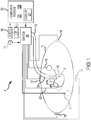
- a system 8 for conducting cardiac electrophysiology studies by navigating a cardiac catheter into a heart 10 of a patient 11 to measure electrical activity occurring in the heart and to three-dimensionally map the electrical activity and/or information related to or representative of the electrical activity.
- the system 8 is particularly used to measure electrophysiology data at a plurality of points along an endocardial surface, and store the measured data in association with location information for each measurement point at which the electrophysiology data was measured.
- the system 8 can instantaneously locate up to sixty-four electrodes in and/or around a heart and the vasculature of a patient, measure electrical activity at up to sixty-two of those sixty-four electrodes, and provide a three-dimensional map of time domain and/or frequency domain information from the measured electrical activity (e.g., electrograms) for a single beat of the heart 10.
- the number of electrodes capable of being simultaneously monitored is limited only by the number of electrode lead inputs into the system 8 and the processing speed of the system 8.
- the electrodes may be stationary or may be moving.
- the electrodes may be in direct contact with the wall of the heart, or may be merely generally adjacent to the wall of the heart, to collect the electrical activity.
- an array of electrodes is used for collecting electrical activity at multiple locations along the wall of the heart. Such an array electrode is described in detail in U.S. Pat. No. 5,662,108 .
- the localization/mapping system 8 may be the EnSiteTM VelocityTM navigation and visualization system available from St. Jude Medical, Inc. In other embodiments, any other suitable localization/mapping system may be used.
- the patient 11 is depicted schematically as an oval for simplicity.
- Three sets of surface electrodes e.g., patch electrodes
- the X-axis surface electrodes 12, 14 are applied to the patient along a first axis, such as on the lateral sides of the thorax region of the patient (e.g., applied to the patient's skin underneath each arm) and may be referred to as the Left and Right electrodes.
- the Y-axis electrodes 18, 19 are applied to the patient along a second axis generally orthogonal to the X-axis, such as along the inner thigh and neck regions of the patient, and may be referred to as the Left Leg and Neck electrodes.
- the Z-axis electrodes 16, 22 are applied along a third axis generally orthogonal to the X-axis and the Y-axis, such as along the sternum and spine of the patient in the thorax region and may be referred to as the Chest and Back electrodes.
- the heart 10 lies between these pairs of surface electrodes.
- An additional surface reference electrode (e.g., a "belly patch") 21 provides a reference and/or ground electrode for the system 8.
- the belly patch electrode 21 is an alternative to a fixed intra-cardiac electrode 31. It should also be appreciated that in addition, the patient 11 will have most or all of the conventional electrocardiogram (ECG) system leads in place. This ECG information is available to the system 8 although not illustrated in the FIG. 1 .
- ECG electrocardiogram
- a representative catheter 13 having at least a single electrode 17 is also shown.
- This representative catheter electrode 17 is referred to as the "roving electrode” or “measurement electrode” throughout the specification.
- the system 8 may comprise up to sixty-four electrodes on up to twelve catheters disposed within the heart and/or vasculature of the patient.
- this embodiment is merely exemplary, and any number of electrodes and catheters may be used within the scope of the present invention.
- the fixed reference electrode 31 (e.g., attached to a wall of the heart 10) is shown on a second catheter 29.
- this electrode 31 may be stationary (e.g., attached to or near the wall of the heart) or disposed in a fixed spatial relationship with the roving electrode 17.
- the fixed reference electrode 31 may be used in addition to or alternatively to, the surface reference electrode 21 described above.
- a coronary sinus electrode or other fixed electrode in the heart 10 can be used as a reference for measuring voltages and displacements.
- Each surface electrode is coupled to the multiplex switch 24, and the pairs of electrodes are selected by software running on a computer 20, which couples the electrodes to a signal generator 25.
- the computer 20, for example, may comprise a conventional general-purpose computer, a special-purpose computer, a distributed computer, or any other type of computer.
- the computer 20 may comprise one or more processors, such as a single central-processing unit, or a plurality of processing units, commonly referred to as a parallel processing environment.
- the signal generator 25 excites a pair of electrodes, for example the Y-axis electrodes 18, 19, which generates an electric field in the body of the patient 11 and the heart 10.
- the remaining surface electrodes are referenced to the surface electrode 21, and the voltages induced on these remaining electrodes are filtered via a low pass filter (LPF) 27.
- the LPF 27 may, for example, comprise an anti-aliasing filter (e.g., a 300 Hz analog LPF).
- A/D analog-to-digital
- Further low pass filtering of the digital data signal may be subsequently performed by software executed on the computer 20 to remove electronic noise and cardiac motion artifact. This filtering may, for example, comprise a user-selectable cutoff frequency used to reduce noise.
- the surface electrodes are divided into driven and non-driven electrode sets.
- a pair of surface electrodes e.g., the X-axis electrodes 12, 14
- the remaining, non-driven surface electrodes and other reference electrodes, if any, e.g., the Y-axis electrodes 18, 19, the Z-axis electrodes 16, 22, the surface reference electrode 21, and, if present, the fixed reference electrode 31
- the remaining, non-driven surface electrodes and other reference electrodes if any, are used as references to synthesize the position of any intracardial electrodes.
- three nominally orthogonal electric fields are generated by a series of driven and sensed electric dipoles in order to realize catheter navigation in a biological conductor.
- these orthogonal fields can be decomposed and any pairs of surface electrodes can be driven as dipoles to provide effective electrode triangulation.
- nonorthogonal methodologies add to the flexibility of the system.
- the potentials measured across an intra-cardiac electrode 17 resulting from a predetermined set of drive (source-sink) configurations are combined algebraically to yield the same effective potential as would be obtained by simply driving a uniform current along the orthogonal axes.
- any two of the surface electrodes 12, 14, 16, 18, 19, 22 may be selected as a dipole source and drain with respect to a ground reference, e.g., the belly patch 21, while the unexcited electrodes measure voltage with respect to the ground reference.
- the measurement electrode 17 placed in the heart 10 is exposed to the field from a current pulse and its voltage is measured with respect to ground, e.g., with respect to the belly patch 21.
- the catheters within the heart may contain multiple electrodes, and each electrode potential may be measured.
- at least one electrode may be fixed to the interior surface of the heart to form a fixed reference electrode 31, which is also measured with respect to ground. Data sets from each of the surface electrodes, the internal electrodes, and the virtual references are all used to determine the location of the measurement electrode 17 or other electrodes within the heart 10.
- All of the raw electrode voltage data is measured by the A/D converter 26 and stored by the computer 20 under the direction of software. This electrode excitation process occurs rapidly and sequentially as alternate sets of surface electrodes are selected and the remaining non-driven electrodes are used to measure voltages. This collection of voltage measurements is referred to herein as the "electrode data set,"
- the software has access to each individual voltage measurement made at each electrode during each excitation of each pair of surface electrodes.
- the raw electrode data is used to determine the "base" location in three-dimensional space (X, Y, Z) of the electrodes inside the heart, such as the roving electrode 17, and any number of other electrodes located in or around the heart and/or vasculature of the patient 11.
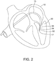
- FIG. 2 shows a catheter 13, which may be a conventional electrophysiology (EP) catheter, extending into the heart 10.
- the catheter 13 extends into the left ventricle 50 of the heart 10.
- the catheter 13 comprises the distal electrode 17 discussed above with respect to FIG. 1 and has additional electrodes 52, 54, and 56. Since each of these electrodes lies within the patient (e.g., in the left ventricle of the heart in this example), location data may be collected simultaneously for each of the electrodes.
- At least one of the electrodes 17, 52, 54, and 56 can be used to measure electrical activity (e.g., voltage) on the surface of the heart 10.
- the system 8 first selects a set of electrodes and then drives them with current pulses. While the current pulses are being delivered, electrical activity, such as the voltages measured at least one of the remaining surface electrodes and in vivo electrodes are measured and stored. At this point, compensation for artifacts, such as respiration and/or impedance shifting may be performed as indicated above.
- various location data points are collected by the system 8 that are associated with multiple electrode locations (e.g., endocardial electrode locations). Each point in the set has coordinates in space.
- the system 8 collects location data points for up to sixty-four electrodes that may be located on up to twelve catheters simultaneously or in close proximity to one another. However, smaller or larger data sets may be collected and result in less complex and lower resolution or more complex and higher resolution representations of the heart, respectively.
- the electrode data may also be used to create a respiration compensation value used to improve the raw location data for the electrode locations as described in U.S. Patent No. 7,263,397 .
- the electrode data may also be used to compensate for changes in the impedance of the body of the patient as described, for example, in U.S. patent 7,885,707 .
- the data used to determine the location of the electrode(s) within the heart are measured while the surface electrode pairs impress an electric field on the heart.
- a number of electrode locations may be collected by either sampling a number (e.g., sixty-two electrodes spread among up to twelve catheters) simultaneously or in sequence (e.g., multiplexed) and/or by sampling one or more electrodes (e.g., the roving electrode 17) being moved within the patient (e.g., a chamber of the heart).
- the location data for individual electrodes are sampled simultaneously, which allows for collection of data at a single stage or phase of a heartbeat.
- location data may be collected either synchronously with one or more phases of the heartbeat or without regard for any particular stage of the heartbeat.
- data corresponding to locations along the wall of the heart will vary with time.
- the data corresponding to the outer or inner locations may be used to determine the position of the heart wall at the maximum and minimum volumes, respectively. For example, by selecting the most exterior points it is possible to create a "shell" representing the shape of the heart at its greatest volume.
- a three-dimensional model of a portion of the patient may be created from the location data points, e.g., during the same or a previous procedure, or a previously generated three-dimensional model, e.g., a segmented CT or MRI scan image, may be used.
- a segmented model indicates that a subregion of a three-dimensional image has been digitally separated from a larger three-dimensional image, e.g., an image of the right atrium separated from the rest of the heart.
- Exemplary segmentation applications include ANALYZE (Mayo, Minneapolis, Minn.), VerismoTM (St. Jude Medical, Inc., St.
- the exterior-most location points in the data can be used to determine a shape corresponding to the volume of a region of the patient's heart.
- a convex hull may be generated using standard algorithms such as the Qhull algorithm.
- the Qhull algorithm for example, is described in Barber, C. B., Dobkin, D. P., and Huhdanpaa, H. T., "The Quickhull algorithm for convex hulls," ACM Trans. on Mathematical Software, 22(4):469-483, December 1996 .
- Other algorithms used to compute a convex hull shape are known and may also be suitable for use in implementing the invention.
- This surface is then re-sampled over a more uniform grid and interpolated to give a reasonably smooth surface stored as a three-dimensional model for presentation to the physician during the same or a later procedure.
- Such a three-dimensional model for example, provides an estimated boundary of the interior of the heart region from the set of points.
- FIG. 3 is a block diagram of the computer system 20.
- the computer system 20 includes the computing device 32, the display device 23, and the input device 38.
- the computing device 32 includes a display adapter 40 communicatively coupling the computing device 32 to the display device 23.
- Display device 23 may include, without limitation, a monitor, a television display, a plasma display, a liquid crystal display (LCD), a display based on light emitting diodes (LED), a display based on a plurality of organic light-emitting diodes (OLEDs), a display based on polymer light-emitting diodes (PLEDs), a display based on a plurality of surface-conduction electron-emitters (SEDs), a display including a projected and/or reflected image or any other suitable electronic device or display mechanism.
- LCD liquid crystal display
- LED light emitting diodes
- OLEDs organic light-emitting diodes
- PLEDs polymer light-emitting diodes
- display device 23 includes a touch-screen with an associated touch-screen controller.
- An interface adapter 42 couples the computing device 32 to the input device 38.
- Computing device 32 includes an input 44 configured to receive electrode signals through A/D converter 26.
- An output 46 couples control signals from computing device 32 to multiplex switch 24.
- Input device 38 includes, without limitation, a keyboard, a keypad, a touch-sensitive screen, a mouse, a scroll wheel, a pointing device, an audio input device employing speech-recognition software, and/or any suitable device that enables a user to input data into computing device 32.
- input device 38 and display device 23 are integrated into a single input/display device, such as in a touch screen display device.
- the computing device 32 includes a processor 34 and a memory device 36 coupled to the processor 34.
- the term "processor” refers herein generally to any programmable system including systems and microcontrollers, reduced instruction set circuits (RISC), application specific integrated circuits (ASIC), programmable logic circuits, field programmable gate array (FPGA), gate array logic (GAL), programmable array logic (PAL), digital signal processor (DSP), and any other circuit or processor capable of executing the functions described herein.
- RISC reduced instruction set circuits
- ASIC application specific integrated circuits
- FPGA field programmable gate array
- GAL gate array logic
- PAL programmable array logic
- DSP digital signal processor
- the memory device 36 stores program code and instructions, executable by the processor 34. When executed by the processor 34, the program code and instructions cause the processor 34 to operate as described herein.
- the memory device 36 may include, but is not limited to only include, non-volatile RAM (NVRAM), magnetic RAM (MRAM), ferroelectric RAM (FeRAM), read only memory (ROM), flash memory and/or Electrically Erasable Programmable Read Only Memory (EEPROM). Any other suitable magnetic, optical and/or semiconductor memory, by itself or in combination with other forms of memory, may be included in the memory device 36.
- the memory device 36 may also be, or include, a detachable or removable memory, including, but not limited to, a suitable cartridge, disk, CD ROM, DVD or USB memory. Although illustrated separate from the processor 34, memory device 36 may be integrated with the processor 34.
- the memory device 36 stores instructions (e.g., software code) that, when executed by the processor 34, cause the processor 34 to operate as described above and in accordance with the methods set forth herein.
- instructions e.g., software code
- the display 23 of the system 8 shown in Figure 1 may be used to show data to a user, such as a physician, and to present certain options that allow the user to tailor the configuration of the system 8 for a particular use.
- the display may include a three-dimensional model of the heart 10. The locations of electrodes on one or more catheters may be mapped to the three-dimensional model.
- Other data that may be mapped to the heart surface model include, for example, the magnitude of a measured voltage, the timing relationship of a signal with respect to heartbeat events. Further, the peak-to-peak voltage measured at a particular location on the heart wall may be mapped to show areas of diminished conductivity and may reflect an infarct region of the heart.
- Atrial electrogram information may be mapped to the three-dimensional model.
- CFE information refers to irregular electrical activation (e.g., atrial fibrillation) in which an electrogram comprises at least two discrete deflections and/or perturbation of the baseline of the electrogram with continuous deflection of a prolonged activation complex (e.g., over a 10 second period). Electrograms having very fast and successive activations are, for example, consistent with myocardium having short refractory periods and micro-reentry.
- the presence of CFE information can be detected from the electrophysiology (EP) information (e.g., electrograms) collected by an electrode.
- EP electrophysiology
- time instant and/or other quantifications of the fractionation of the electrogram may be used to determine the presence and/or absence of CFE information.
- CFE information may be quantified using one or more indices.
- a voltage-based index is used to characterize the fractionation of a given electrogram.
- the voltage-based index is a voltage-based isoelectric index (v-IEI).
- v-IEI voltage-based isoelectric index
- the value of v-IEI for a particular electrogram is an indication of how much of the electrogram consists of isoelectric portions. Less fractionated electrograms are typically associated with a greater percentage of isoelectric portions than more fractionated electrograms.
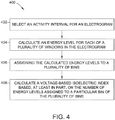
- Figure 4 is a flow diagram of an exemplary method 400 for evaluating an electrogram segment.
- the method 400 will be described with reference to the system 8 and the computing device 20, but may be implemented using any suitable electrophysiology devices and/or computing devices.
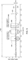
- Figure 5 is an example electrogram 500 having a segment length 502.
- the electrogram 500 is graphed as an amplitude, in millivolts (mV) as a function of time, in seconds.
- the segment length 502 is about one second.
- the segment length 502 is variable and selectable by the user of the system 8, and the segment length 502 may be any suitable length of time. In some embodiments, the segment length is between five seconds and eight seconds.
- an activity interval is selected.
- the activity interval is a period of time that is shorter than the segment length.
- the activity interval defines a temporal window in which cardiac activity is searched for, and is generally selected to be long enough to capture typical cardiac activity, but small enough to include only temporally local phenomena.
- the activity interval may be user selected and/or a default activity interval may be predefined in computing device 20. In an example embodiment, the activity interval is selected to be 10 milliseconds (ms) by default. In other embodiments, any other suitable activity interval may be defined as a default activity interval. It should be understood that selecting the activity interval may include selecting a default activity interval by not specifying, changing, or selecting a different activity interval.
- An energy level is calculated at 404 for a plurality of windows in the electrogram.
- Each window has a length equal to the activity interval.
- one window is defined for each sample (e.g., each discrete electrode measurement recorded by the system 8) in the electrogram, with the window beginning at the time of the sample and continuing for the length of the activity interval.
- the windows may begin at any other suitable time.
- more or fewer windows are defined.
- the sampling rate of the system 8 is about 2,034 samples per second. In other embodiments, the sampling rate of the system 8 is any other sampling rate that provides satisfactory resolution of the electrogram.
- three windows 504, 506 and 508 are shown, each of which is defined by an activity interval 510.
- the windows 504, 506, and 508 are defined by an activity interval 510 of about 90 ms. In other embodiments, the activity interval may be selected to be a shorter length of time, such as about 10 ms. As described above, in an example embodiment, one window is defined for each sample in the electrogram segment. If the system 8 is sampling 2,034 samples per second, the one second long electrogram 500 shown in Figure 5 would have 2,034 samples and up to 2,034 windows. For clarity and simplicity, only three windows 504, 506, and 508 of the 2,034 possible windows are shown in Figure 5 .
- the energy level (also referred to sometimes as an activity level) is calculated by summing the absolute value of the measured amplitude of each sample in the window.
- the sampling rate of the system 8 is about 2,034 samples per second
- the activity interval is about 10 ms
- each window includes about twenty samples.
- the system 8 After the energy level has been calculated for each window of the segment, the system 8 will have M separate energy values, where M is the number of windows defined for the electrogram segment. As can be seen in Figure 5 , window 506, which includes a generally isoelectric portion of the electrogram segment with an amplitude around zero, will have a much lower energy level E(i) than windows 504 and 508, which include multiple small deflections and a large deflection respectively.
- the calculated energy levels are assigned to a plurality of bins at 406,
- the bins define a histogram with a range from the minimum calculated energy level E(i) to the maximum calculated energy level E(i).
- the bins are each assigned a non-overlapping range of possible energy values between the minimum E(i) and the maximum E(i), such that every possible energy value between the minimum and the maximum values of E(i) are associated with a bin.
- the size of the range of each bin is determined by the number of bins, with the range of calculated E(i) values divided equally among the bins. In other embodiments, the bins need not all have a same range size.
- the number of bins is a fixed, predetermined number of bins.
- the number of bins is a user selectable number of bins.
- the number of bins is determined by the system 8, as will be described in more detail below.
- the energy value E(i) for each window is assigned to the bin with the energy range that encompasses the energy value E(i) of that window.
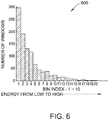
- the system 8 tracks the number of windows assigned to each bin. This data is used to populate a histogram of the number of windows in each bin ordered from lowest energy bin to highest energy bin.
- An example histogram 600 with twenty bins is shown in Figure 6 .
- the first bin is the bin that includes the window(s) having the lowest energy values, including the windows with an energy value E(i) equal to the minimum energy value E(i).
- low energy value windows are typically associated with isoelectric portions of the electrogram.
- the lowest energy first bin B n (1) is associated with isoelectric portions of the electrogram segment.
- a voltage-based isoelectric index (v-IEI) is calculated based at least in part on the number of energy values E(i) assigned to a particular bin of the plurality of bins.
- the particular bin is the bin with the lowest energy values.
- the particular bin is the first bin.
- the index v-IEI is the ratio of low energy windows to all windows in the electrogram segment.
- the index v-IEI may be expressed as a percentage by multiplying the result of equation (2) by 100%.
- a low percentage v-IEI describes an electrogram segment with a small percentage of (or no) isoelectric portions, which may indicate a high level of fractionation.
- a high percentage v-IEI describes an electrogram segment with a high percentage of isoelectric portions, which may indicate a low level of (or no) fractionation.
- the calculated v-IEI may be used on its own as an index describing the amount of fractionation in an electrogram segment.
- the v-IEI may be displayed numerically, mapped to a three dimensional map of the heart, or presented to a user of the system 8 in any suitable manner. Additionally, or alternatively, the v-IEI may be combined with one or more other indices to create a composite, or fused, index of fractionation.
- Figures 7 and 8 are example electrogram segments and associated histograms produced according to the method described herein.
- Figure 7 includes an electrogram 700 with a one second segment length and a relatively high degree of fractionation.
- a 10 ms activity interval was selected, and the energy level E(i) was calculated for each window on the electrogram 700.
- the calculated energy levels were assigned to about twenty bins, as shown in the histogram 702.
- the v-IEI calculated for the electrogram 700 was 0.0693 (or 6.93%).
- Figure 8 includes an electrogram 800 with a one second segment length and very little fractionation.
- a 10 ms activity interval was selected, and the energy level E(i) was calculated for each window on the electrogram 800.
- the calculated energy levels were assigned to about sixty bins (some bins contain no energy levels), as shown in the histogram 802.
- the v-IEI calculated for the electrogram 800 was 0.8624 (or 86.24%).
- the number of bins to which the energy levels E(i) are assigned is determined by the system 8 (and more particularly, by the computing device 20).
- the number of bins is found using an adaptive binning method to determine a number of bins that produces a lowest energy bin that accurately collects windows including isoelectric intervals.
- Figure 9 is a flow diagram of an exemplary method 900 for determining the number of bins for use in a method of calculating a voltage-based isoelectric index, such as in the method 400 shown in Figure 4 .
- the method 900 is applied to data collected for a particular electrogram.
- an initial number of bins is selected for the electrogram segment. Because the method 900 is an adaptive iterative algorithm, the closer that the initial number of bins is set to the final number of bins, the fewer iterations will be needed to reach the final number of bins. Reducing the number of iterations may reduce the amount of processing needed to be performed and free computational power for other uses. Setting the initial N too high, however, may prevent the method 900 from determining a proper number of bins to achieve the desired correlation between the lowest energy bin and windows containing isoelectric segments. Accordingly, in some embodiments, the initial number of bins is selected to be one bin. In other embodiments, the initial N is selected to be ten bins.
- the initial N is selected to be any number greater than one and less than an anticipated final number of bins.
- the initial number of bins may be user selected and/or a default value may be predefined in computing device 20.
- a default value for the initial number of bins is set as ten bins.
- any other suitable default value for the initial N may be selected. It should be understood that selecting the initial number of bins may include selecting/accepting a default initial N by not specifying, changing, or selecting a number N.
- N number of bins are created. Each bin has a range of energy values as described above. At 906, the energy values calculated for each window defined for the electrogram segment are assigned to the bin having a range in which its energy value is contained.
- the energy midpoint (EMB) of the lowest energy bin is calculated at 908.
- the energy midpoint EMB is compared to a noise level energy threshold E n , which will be described in more detail below. If the EMB is less than the noise level energy threshold E n , the method 900 is completed and the number of bins is set at the current number of bins N. If the EMB is not less than the E n , the method 900 continues to 912. At 912, the number of bins N is incremented by one and the method 900 returns to 904. Thus, the method 900 continues with the number of bins increasing in each iteration until the EMB is less than the E n .
- the energy noise level threshold E n is determined based on a peak-to-peak sensitivity setting of the system 8.
- the sensitivity setting is typically a user selected value. Alternatively, or additionally, the sensitivity setting may be a default/preset sensitivity setting.
- the peak-to-peak sensitivity setting is an voltage amplitude (A) in millivolts. In Figure 5 , for example, the peak-to-peak sensitivity 512 is defined by thresholds 514.
- To determine the threshold E n an energy level is calculated for a hypothetical sinusoidal noise signal between one half A and negative one half A. The frequency of the sinusoidal signal is determined by the frequency of the alternating current (AC) power supplied to the system 8.
- AC alternating current
- the hypothetical sinusoidal noise signal has a frequency of 60 Hz.
- a 50 Hz hypothetical sinusoidal noise signal is used.
- the energy level is calculated for one window of the selected activity interval according to equation (1).
- any other suitable energy noise level threshold E n including a predetermined E n and/or a differently calculated E n , may be used.
- the voltage-based isoelectric index v-IEI may be utilized as an index by itself or may be combined with one or more other indices.
- the v-IEI and CFE mean appear to be relating complimentary information.
- the v-IEI metric is combined with the CFE mean to provide a hybrid index for evaluation of electrogram segments.
- the v-IEI index may be combined with any other index for evaluation of electrograms including, for example, CFE StdDev, SCI, ACI, and ICL.
- the v-IEI index ranges between zero and one, while the CFE mean ranges from zero to the length of the electrogram segment in milliseconds. In some embodiments, the maximum segment length, and accordingly the maximum CFE mean, is 8,000 ms.
- the parameter T in equation (4) may be treated as a center of interest.
- T 125 ms corresponds to a suggested CFE mean cutoff point between CFAE electrograms and non CFAE electrograms.
- T may have a different value to highlight a different range of CFE mean values.
- the parameter ⁇ governs the slope of the sigmoid function. The larger the value of ⁇ , the sharper the slope of the sigmoid function will be. Thus, ⁇ may be selected based on the range of data in which one is interested. In other embodiments, a different sigmoid function, a linear function, and/or another suitable monotonic function may be used to map the CFE mean and v-IEI to the same range.
- the v-IEI and CFE mean values may be combined.
- the v-IEI and CFE mean are combined using an F-measure.
- the F-measure also referred to as an F1 score
- F 1 2 M 1 M 2 M 1 + M 2
- the F-measure produced by combining v-IEI and CFE mean values using equation (5) assigns equal weight to the v-IEI and CFE mean values.
- the variable ⁇ gives different weighting to the harmonies of equation (6).
- the value of ⁇ is positive. If the value of ⁇ is 1, equation (6) reduces to equation (5) and M 1 and M 2 receive equal emphasis. If the value of a is smaller than 1, M 1 receives more emphasis than M 2 . If the value of ⁇ is greater than 1, more emphasis is placed on M 2 than M 1 .
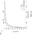
- FIG. 10 is a graph 1000 summarizing the results.
- trace 1002 is the CFE mean
- trace 1004 is the v-IEI
- 1006 is the F-measure combined CFE mean and v-IEI.
- the graph 100 generally shows greater sensitivity and specificity achieved using the F-measure than is achieved using the CFE mean alone.
- v-IEI mapping in one embodiment, two parameters may be set: a refractory parameter and a floor parameter.
- the refractory parameter defines a minimum segment length considered to be iso-electric.
- the refractory parameter may be in a range from 30 milliseconds (ms) to 60 ms.
- the floor parameter determines a maximum peak to peak voltage to be considered iso-electric.
- the floor parameter may be in a range from 0.03 millivolts (mV) to 0.05 mV, or above a noise floor.
- an v-IEI map is recomputed and redisplayed.
- An overall segment length (e.g., segment length 502 (shown in Fig. 5 )) is also specified.
- the overall segment length may be, for example, in a range from 1 second (s) to 8 s.
- the first row of the table (i.e., "% of all Electrograms") represents the percentage of all acquired electrograms that fit the criterion of the respective columns. For example, 24.70% of all acquired electrograms had a CFE mean of less than 120 ms.
- the second and third rows represent the additional criterion for the column electrograms. For example, 98.42% of the electrograms that had a v-IEI index under 25% were also electrograms with a CFE mean of less than 120 ms. Further, 32.58% of electrograms with a CFE mean of less than 120 ms, had a v-IEI index under 25%. Accordingly, from the experimental data of Table 1, it is apparent that the CFE mean and v-IEI index are related to one another. Other, similar experiments were also conducted with similar results.
Landscapes
- Health & Medical Sciences (AREA)
- Life Sciences & Earth Sciences (AREA)
- Public Health (AREA)
- Medical Informatics (AREA)
- Engineering & Computer Science (AREA)
- General Health & Medical Sciences (AREA)
- Pathology (AREA)
- Biomedical Technology (AREA)
- Cardiology (AREA)
- Molecular Biology (AREA)
- Heart & Thoracic Surgery (AREA)
- Physics & Mathematics (AREA)
- Surgery (AREA)
- Animal Behavior & Ethology (AREA)
- Biophysics (AREA)
- Veterinary Medicine (AREA)
- Data Mining & Analysis (AREA)
- Databases & Information Systems (AREA)
- Epidemiology (AREA)
- Primary Health Care (AREA)
- Physiology (AREA)
- Measurement And Recording Of Electrical Phenomena And Electrical Characteristics Of The Living Body (AREA)
Claims (13)
- Procédé implémenté par ordinateur pour évaluer un électrogramme cardiaque ayant une longueur de segment (502) avec une longueur prédéterminée et contenant une pluralité d'échantillons de données ayant chacun une tension, le procédé implémenté par ordinateur comprenant les étapes consistant à :sélectionner un intervalle d'activité pour l'électrogramme cardiaque, dans lequel l'intervalle d'activité est une période de temps plus courte que la longueur du segment (502) ;définir une pluralité de fenêtres (504, 506, 508), une fenêtre (504, 506, 508) pour chaque échantillon de données, où chaque fenêtre de la pluralité de fenêtres correspondant à une durée définie par l'intervalle d'activité (510) et comprenant une pluralité d'échantillons de données de l'électrogramme cardiaque ;calculer un niveau d'énergie (E(i)) pour chaque fenêtre de la pluralité de fenêtres (504, 506, 508) de l'électrogramme sur la base des tensions de la pluralité d'échantillons de données dans chaque fenêtre ;définir une pluralité de fichiers ;attribuer des niveaux d'énergie calculés (E(i)) à la pluralité de fichiers définissant un histogramme avec une plage allant d'un niveau d'énergie calculé minimum (E(i)) à un niveau d'énergie calculé maximum (E(i)) tels que tous les niveaux d'énergie possible entre les valeurs minimale et maximale sont associés à un fichier; etcalculer un indice (v-IEI) basé au moins en partie sur un nombre de niveaux d'énergie (E(i)) attribué à un fichier particulier de la pluralité des fichier.
- Procédé implémenté par ordinateur selon la revendication 1, dans lequel le calcul d'un niveau d'énergie (Ei) pour chaque fenêtre comprend la sommation d'une valeur absolue de la tension de chaque échantillon de données dans la fenêtre.
- Procédé implémenté par ordinateur selon l'une quelconque des revendications précédentes, dans lequel chaque fichier de la pluralité de fichiers est associé à une plage de niveaux d'énergie, et dans lequel l'affectation des niveaux d'énergie calculés (E(i)) à la pluralité de fichiers comprend l'attribution de chaque niveau d'énergie dans le fichier associée à la plage de niveaux d'énergie contenant ledit niveau d'énergie.
- Procédé implémenté par ordinateur selon l'une quelconque des revendications précédentes, dans lequel la définition de la pluralité de fichiers comprend la détermination du nombre de fichiers à définir en augmentant de manière itérative le nombre de fichiers jusqu'à ce qu'un point milieu du fichier avec la plage d'énergie la plus basse des niveaux d'énergie est inférieur à une valeur seuil de bruit.
- Procédé implémenté par ordinateur selon la revendication 4, comprenant en outre la définition de la valeur seuil de bruit comme une fonction d'un réglage de sensibilité pour l'électrogramme.
- Procédé implémenté par ordinateur selon l'une quelconque des revendications précédentes, dans lequel chaque fichier de la pluralité de fichiers est associé à une plage de niveaux d'énergie, et dans lequel le calcul de l'indice (v-IEI) basé au moins en partie sur un nombre de niveaux d'énergie affecté à un fichier particulier comprend le calcul de l'indice (v-IEI) sur la base au moins en partie d'un nombre de niveaux d'énergie attribués au fichier avec la plage d'énergie la plus basse des niveaux d'énergies.
- Procédé implémenté par ordinateur selon l'une quelconque des revendications précédentes, comprenant en outre la génération d'un histogramme (600) du nombre de niveaux d'énergie attribués à chaque fichier de la pluralité de fichiers.
- Système d'évaluation d'un électrogramme contenant une pluralité d'échantillons de données ayant chacun une tension, le système comprenant :
un dispositif informatique (32) configuré pour recevoir les échantillons de données, le dispositif informatique comprenant :un processeur (34) ; etau moins un dispositif de mémoire (36) couplé audit processeur (34), le dispositif de mémoire (36) stockant des instructions exécutables par ordinateur qui, lorsqu'elles sont exécutées par le processeur (34), amènent le dispositif informatique (32) à exécuter le procédé selon à l'une quelconque des revendications 1 à 7. - Système selon la revendication 8, dans lequel le dispositif de mémoire (36) stocke en outre des instructions exécutables par un ordinateur qui, lorsqu'elles sont exécutées par le processeur (34), amènent le dispositif de calcul (32) à calculer le niveau d'énergie (E(i)) pour chaque fenêtre en sommant une valeur absolue de la tension de chaque échantillon de données dans la fenêtre.
- Système selon l'une quelconque des revendications 8 ou 9, dans lequel chaque fichier de la pluralité de fichiers est associé à une plage de niveaux d'énergie, et dans lequel le dispositif de mémoire (36) stocke en outre des instructions exécutables par ordinateur qui, lorsqu'elles sont exécutées par le processeur (34), amène le dispositif informatique (32) à attribuer chaque niveau d'énergie au fichier associée avec la plage de niveaux d'énergie contenant ledit niveau d'énergie.
- Système selon l'une quelconque des revendications 8 à 10, dans lequel le dispositif de mémoire (36) stocke en outre des instructions exécutables par ordinateur qui, lorsqu'elles sont exécutées par le processeur (34), amènent le dispositif informatique (32) à déterminer le nombre de segments à définir par augmentation itérative du nombre de fichiers jusqu'à ce qu'un point milieu du fichier avec la plage d'énergie la plus basse des niveaux d'énergie soit inférieure à une valeur seuil de bruit.
- Système selon l'une quelconque des revendications 8 à 11, dans lequel chaque fichier de la pluralité de fichiers est associé à une plage de niveaux d'énergie, et dans lequel le fichier particulier de la pluralité de fichiers est le fichier avec la plage d'énergie la plus basse de niveaux d'énergie.
- Système selon l'une quelconque des revendications 8 à 12, comprenant en outre un dispositif d'affichage (23), dans lequel le dispositif de mémoire (36) stocke en outre des instructions exécutables par ordinateur qui, lorsqu'elles sont exécutées par le processeur (34), amènent le dispositif informatique (32) à générer un histogramme (600) du nombre de niveaux d'énergie attribués à chaque fichier de la pluralité de fichier.
Applications Claiming Priority (2)
| Application Number | Priority Date | Filing Date | Title |
|---|---|---|---|
| US201361897597P | 2013-10-30 | 2013-10-30 | |
| PCT/US2014/062778 WO2015066112A1 (fr) | 2013-10-30 | 2014-10-29 | Systèmes de cartographie cardiaque et procédé pour l'évaluation à base de tension d'électrogrammes |
Publications (2)
| Publication Number | Publication Date |
|---|---|
| EP3021745A1 EP3021745A1 (fr) | 2016-05-25 |
| EP3021745B1 true EP3021745B1 (fr) | 2019-04-10 |
Family
ID=51945999
Family Applications (1)
| Application Number | Title | Priority Date | Filing Date |
|---|---|---|---|
| EP14802238.7A Active EP3021745B1 (fr) | 2013-10-30 | 2014-10-29 | Systèmes de cartographie cardiaque et procédé pour l'évaluation à base de tension d'électrogrammes |
Country Status (5)
| Country | Link |
|---|---|
| US (3) | US9990470B2 (fr) |
| EP (1) | EP3021745B1 (fr) |
| JP (1) | JP6273355B2 (fr) |
| CN (1) | CN105578957B (fr) |
| WO (1) | WO2015066112A1 (fr) |
Cited By (2)
| Publication number | Priority date | Publication date | Assignee | Title |
|---|---|---|---|---|
| US12310737B2 (en) | 2020-09-30 | 2025-05-27 | Boston Scientific Scimed, Inc. | Interactive 2D scatter plot of EGM characteristic metrics |
| US12471828B2 (en) | 2020-09-30 | 2025-11-18 | Boston Scientific Scimed, Inc. | Electrophysiology system and method for determining local cycle length and local duty cycle |
Families Citing this family (5)
| Publication number | Priority date | Publication date | Assignee | Title |
|---|---|---|---|---|
| EP3565459B1 (fr) * | 2017-03-02 | 2024-03-27 | St. Jude Medical, Cardiology Division, Inc. | Système et méthode de différentation entre tissus adipeux et tissus de cicatrisation durant une cartographie électro-physiologique |
| US11646113B2 (en) * | 2017-04-24 | 2023-05-09 | Biosense Webster (Israel) Ltd. | Systems and methods for determining magnetic location of wireless tools |
| US11482338B2 (en) * | 2018-03-06 | 2022-10-25 | Biosense Webster (Israel) Ltd. | Simulation of heart pacing for modeling arrhythmia |
| US11844616B2 (en) * | 2019-08-13 | 2023-12-19 | Biosense Webster (Israel) Ltd. | Enhanced visualization of organ electrical activity |
| US12588858B2 (en) * | 2021-09-07 | 2026-03-31 | Biosense Webster (Israel) Ltd. | Weighting projected electrophysiological wave velocity with sigmoid curve |
Family Cites Families (19)
| Publication number | Priority date | Publication date | Assignee | Title |
|---|---|---|---|---|
| US4453551A (en) * | 1981-02-25 | 1984-06-12 | John Anderson | Apparatus for pattern recognition of ECG signals for detecting fibrillation |
| JPH0366358A (ja) | 1989-08-03 | 1991-03-22 | Terumo Corp | 生体信号計測装置 |
| US5301677A (en) * | 1992-02-06 | 1994-04-12 | Cardiac Pacemakers, Inc. | Arrhythmia detector using delta modulated turning point morphology of the ECG wave |
| US5662108A (en) | 1992-09-23 | 1997-09-02 | Endocardial Solutions, Inc. | Electrophysiology mapping system |
| US7263397B2 (en) | 1998-06-30 | 2007-08-28 | St. Jude Medical, Atrial Fibrillation Division, Inc. | Method and apparatus for catheter navigation and location and mapping in the heart |
| US6434417B1 (en) | 2000-03-28 | 2002-08-13 | Cardiac Pacemakers, Inc. | Method and system for detecting cardiac depolarization |
| FI20025039A0 (fi) * | 2002-08-16 | 2002-08-16 | Joni Kettunen | Menetelmä II fysiologisen signaalin analysoimiseksi |
| US8229545B2 (en) | 2005-09-15 | 2012-07-24 | St. Jude Medical, Atrial Fibrillation Division, Inc. | System and method for mapping complex fractionated electrogram information |
| US7885707B2 (en) | 2005-09-15 | 2011-02-08 | St. Jude Medical, Atrial Fibrillation Division, Inc. | Method of scaling navigation signals to account for impedance drift in tissue |
| US8359092B2 (en) | 2007-11-29 | 2013-01-22 | Biosense Webster, Inc. | Determining locations of ganglia and plexi in the heart using complex fractionated atrial electrogram |
| RU2691318C2 (ru) * | 2009-06-12 | 2019-06-11 | Бард Аксесс Системс, Инк. | Способ позиционирования конца катетера |
| WO2011115576A2 (fr) * | 2010-03-15 | 2011-09-22 | Singapore Health Services Pte Ltd | Procédé de prédiction de la capacité de survie d'un patient |
| US8340766B2 (en) | 2010-10-07 | 2012-12-25 | St. Jude Medical, Atrial Fibrillation Division, Inc. | Method and system for identifying cardiac arrhythmia driver sites |
| US9241672B2 (en) * | 2012-02-09 | 2016-01-26 | Sharp Laboratories Of America, Inc. | Determining usability of an acoustic signal for physiological monitoring using frequency analysis |
| WO2013123549A1 (fr) * | 2012-02-20 | 2013-08-29 | Adelaide Research & Innovation Pty Ltd | Méthode d'identification d'une région cardiaque à retirer par ablation |
| US8676305B2 (en) | 2012-03-21 | 2014-03-18 | Biosense Webster (Israel) Ltd. | Automated analysis of complex fractionated electrograms |
| US9833157B2 (en) | 2012-04-23 | 2017-12-05 | Biosense Webster (Israel) Ltd. | Cardiac activation time detection |
| US8862213B2 (en) | 2012-07-26 | 2014-10-14 | National Central University | System and method for improved complex fractionated electrogram ablation |
| US9572505B2 (en) | 2012-10-11 | 2017-02-21 | Medtronic, Inc. | Determining onsets and offsets of cardiac depolarization and repolarization waves |
-
2014
- 2014-10-29 EP EP14802238.7A patent/EP3021745B1/fr active Active
- 2014-10-29 WO PCT/US2014/062778 patent/WO2015066112A1/fr not_active Ceased
- 2014-10-29 CN CN201480053812.0A patent/CN105578957B/zh active Active
- 2014-10-29 JP JP2016522093A patent/JP6273355B2/ja active Active
- 2014-10-29 US US14/527,015 patent/US9990470B2/en active Active
-
2018
- 2018-05-04 US US15/971,054 patent/US10991464B2/en active Active
-
2021
- 2021-04-08 US US17/225,390 patent/US20210225523A1/en not_active Abandoned
Non-Patent Citations (1)
| Title |
|---|
| None * |
Cited By (2)
| Publication number | Priority date | Publication date | Assignee | Title |
|---|---|---|---|---|
| US12310737B2 (en) | 2020-09-30 | 2025-05-27 | Boston Scientific Scimed, Inc. | Interactive 2D scatter plot of EGM characteristic metrics |
| US12471828B2 (en) | 2020-09-30 | 2025-11-18 | Boston Scientific Scimed, Inc. | Electrophysiology system and method for determining local cycle length and local duty cycle |
Also Published As
| Publication number | Publication date |
|---|---|
| US20180350469A1 (en) | 2018-12-06 |
| CN105578957A (zh) | 2016-05-11 |
| JP2016533216A (ja) | 2016-10-27 |
| US9990470B2 (en) | 2018-06-05 |
| EP3021745A1 (fr) | 2016-05-25 |
| WO2015066112A1 (fr) | 2015-05-07 |
| JP6273355B2 (ja) | 2018-01-31 |
| CN105578957B (zh) | 2018-06-29 |
| US10991464B2 (en) | 2021-04-27 |
| US20150120207A1 (en) | 2015-04-30 |
| US20210225523A1 (en) | 2021-07-22 |
Similar Documents
| Publication | Publication Date | Title |
|---|---|---|
| EP3021746B1 (fr) | Système de cartographie cardiaque et méthode de détection d'activation bidirectionnelle d'électrocardiogrammes | |
| EP2298165B1 (fr) | Systeme de mappage tridimensionnel d'informations d'electrophysiologie | |
| US8229545B2 (en) | System and method for mapping complex fractionated electrogram information | |
| US10991464B2 (en) | Cardiac mapping system and method for voltage-based evaluation of electrograms | |
| EP3383257B1 (fr) | Procédés et systèmes de cartographie de l'activité cardiaque | |
| EP3344135A1 (fr) | Procédés et systèmes de cartographie de la restitution cardiaque |
Legal Events
| Date | Code | Title | Description |
|---|---|---|---|
| PUAI | Public reference made under article 153(3) epc to a published international application that has entered the european phase |
Free format text: ORIGINAL CODE: 0009012 |
|
| 17P | Request for examination filed |
Effective date: 20160215 |
|
| AK | Designated contracting states |
Kind code of ref document: A1 Designated state(s): AL AT BE BG CH CY CZ DE DK EE ES FI FR GB GR HR HU IE IS IT LI LT LU LV MC MK MT NL NO PL PT RO RS SE SI SK SM TR |
|
| AX | Request for extension of the european patent |
Extension state: BA ME |
|
| STAA | Information on the status of an ep patent application or granted ep patent |
Free format text: STATUS: EXAMINATION IS IN PROGRESS |
|
| 17Q | First examination report despatched |
Effective date: 20170102 |
|
| DAX | Request for extension of the european patent (deleted) | ||
| GRAP | Despatch of communication of intention to grant a patent |
Free format text: ORIGINAL CODE: EPIDOSNIGR1 |
|
| STAA | Information on the status of an ep patent application or granted ep patent |
Free format text: STATUS: GRANT OF PATENT IS INTENDED |
|
| INTG | Intention to grant announced |
Effective date: 20181031 |
|
| GRAS | Grant fee paid |
Free format text: ORIGINAL CODE: EPIDOSNIGR3 |
|
| GRAA | (expected) grant |
Free format text: ORIGINAL CODE: 0009210 |
|
| STAA | Information on the status of an ep patent application or granted ep patent |
Free format text: STATUS: THE PATENT HAS BEEN GRANTED |
|
| AK | Designated contracting states |
Kind code of ref document: B1 Designated state(s): AL AT BE BG CH CY CZ DE DK EE ES FI FR GB GR HR HU IE IS IT LI LT LU LV MC MK MT NL NO PL PT RO RS SE SI SK SM TR |
|
| REG | Reference to a national code |
Ref country code: GB Ref legal event code: FG4D |
|
| REG | Reference to a national code |
Ref country code: CH Ref legal event code: EP Ref country code: AT Ref legal event code: REF Ref document number: 1117579 Country of ref document: AT Kind code of ref document: T Effective date: 20190415 |
|
| REG | Reference to a national code |
Ref country code: IE Ref legal event code: FG4D |
|
| REG | Reference to a national code |
Ref country code: DE Ref legal event code: R096 Ref document number: 602014044552 Country of ref document: DE |
|
| REG | Reference to a national code |
Ref country code: NL Ref legal event code: MP Effective date: 20190410 |
|
| REG | Reference to a national code |
Ref country code: LT Ref legal event code: MG4D |
|
| REG | Reference to a national code |
Ref country code: AT Ref legal event code: MK05 Ref document number: 1117579 Country of ref document: AT Kind code of ref document: T Effective date: 20190410 |
|
| PG25 | Lapsed in a contracting state [announced via postgrant information from national office to epo] |
Ref country code: NL Free format text: LAPSE BECAUSE OF FAILURE TO SUBMIT A TRANSLATION OF THE DESCRIPTION OR TO PAY THE FEE WITHIN THE PRESCRIBED TIME-LIMIT Effective date: 20190410 |
|
| PG25 | Lapsed in a contracting state [announced via postgrant information from national office to epo] |
Ref country code: LT Free format text: LAPSE BECAUSE OF FAILURE TO SUBMIT A TRANSLATION OF THE DESCRIPTION OR TO PAY THE FEE WITHIN THE PRESCRIBED TIME-LIMIT Effective date: 20190410 Ref country code: PT Free format text: LAPSE BECAUSE OF FAILURE TO SUBMIT A TRANSLATION OF THE DESCRIPTION OR TO PAY THE FEE WITHIN THE PRESCRIBED TIME-LIMIT Effective date: 20190910 Ref country code: HR Free format text: LAPSE BECAUSE OF FAILURE TO SUBMIT A TRANSLATION OF THE DESCRIPTION OR TO PAY THE FEE WITHIN THE PRESCRIBED TIME-LIMIT Effective date: 20190410 Ref country code: NO Free format text: LAPSE BECAUSE OF FAILURE TO SUBMIT A TRANSLATION OF THE DESCRIPTION OR TO PAY THE FEE WITHIN THE PRESCRIBED TIME-LIMIT Effective date: 20190710 Ref country code: SE Free format text: LAPSE BECAUSE OF FAILURE TO SUBMIT A TRANSLATION OF THE DESCRIPTION OR TO PAY THE FEE WITHIN THE PRESCRIBED TIME-LIMIT Effective date: 20190410 Ref country code: FI Free format text: LAPSE BECAUSE OF FAILURE TO SUBMIT A TRANSLATION OF THE DESCRIPTION OR TO PAY THE FEE WITHIN THE PRESCRIBED TIME-LIMIT Effective date: 20190410 Ref country code: AL Free format text: LAPSE BECAUSE OF FAILURE TO SUBMIT A TRANSLATION OF THE DESCRIPTION OR TO PAY THE FEE WITHIN THE PRESCRIBED TIME-LIMIT Effective date: 20190410 Ref country code: ES Free format text: LAPSE BECAUSE OF FAILURE TO SUBMIT A TRANSLATION OF THE DESCRIPTION OR TO PAY THE FEE WITHIN THE PRESCRIBED TIME-LIMIT Effective date: 20190410 |
|
| PG25 | Lapsed in a contracting state [announced via postgrant information from national office to epo] |
Ref country code: GR Free format text: LAPSE BECAUSE OF FAILURE TO SUBMIT A TRANSLATION OF THE DESCRIPTION OR TO PAY THE FEE WITHIN THE PRESCRIBED TIME-LIMIT Effective date: 20190711 Ref country code: BG Free format text: LAPSE BECAUSE OF FAILURE TO SUBMIT A TRANSLATION OF THE DESCRIPTION OR TO PAY THE FEE WITHIN THE PRESCRIBED TIME-LIMIT Effective date: 20190710 Ref country code: LV Free format text: LAPSE BECAUSE OF FAILURE TO SUBMIT A TRANSLATION OF THE DESCRIPTION OR TO PAY THE FEE WITHIN THE PRESCRIBED TIME-LIMIT Effective date: 20190410 Ref country code: RS Free format text: LAPSE BECAUSE OF FAILURE TO SUBMIT A TRANSLATION OF THE DESCRIPTION OR TO PAY THE FEE WITHIN THE PRESCRIBED TIME-LIMIT Effective date: 20190410 Ref country code: PL Free format text: LAPSE BECAUSE OF FAILURE TO SUBMIT A TRANSLATION OF THE DESCRIPTION OR TO PAY THE FEE WITHIN THE PRESCRIBED TIME-LIMIT Effective date: 20190410 |
|
| PG25 | Lapsed in a contracting state [announced via postgrant information from national office to epo] |
Ref country code: AT Free format text: LAPSE BECAUSE OF FAILURE TO SUBMIT A TRANSLATION OF THE DESCRIPTION OR TO PAY THE FEE WITHIN THE PRESCRIBED TIME-LIMIT Effective date: 20190410 Ref country code: IS Free format text: LAPSE BECAUSE OF FAILURE TO SUBMIT A TRANSLATION OF THE DESCRIPTION OR TO PAY THE FEE WITHIN THE PRESCRIBED TIME-LIMIT Effective date: 20190810 |
|
| REG | Reference to a national code |
Ref country code: DE Ref legal event code: R097 Ref document number: 602014044552 Country of ref document: DE |
|
| PG25 | Lapsed in a contracting state [announced via postgrant information from national office to epo] |
Ref country code: EE Free format text: LAPSE BECAUSE OF FAILURE TO SUBMIT A TRANSLATION OF THE DESCRIPTION OR TO PAY THE FEE WITHIN THE PRESCRIBED TIME-LIMIT Effective date: 20190410 Ref country code: DK Free format text: LAPSE BECAUSE OF FAILURE TO SUBMIT A TRANSLATION OF THE DESCRIPTION OR TO PAY THE FEE WITHIN THE PRESCRIBED TIME-LIMIT Effective date: 20190410 Ref country code: RO Free format text: LAPSE BECAUSE OF FAILURE TO SUBMIT A TRANSLATION OF THE DESCRIPTION OR TO PAY THE FEE WITHIN THE PRESCRIBED TIME-LIMIT Effective date: 20190410 Ref country code: CZ Free format text: LAPSE BECAUSE OF FAILURE TO SUBMIT A TRANSLATION OF THE DESCRIPTION OR TO PAY THE FEE WITHIN THE PRESCRIBED TIME-LIMIT Effective date: 20190410 Ref country code: SK Free format text: LAPSE BECAUSE OF FAILURE TO SUBMIT A TRANSLATION OF THE DESCRIPTION OR TO PAY THE FEE WITHIN THE PRESCRIBED TIME-LIMIT Effective date: 20190410 |
|
| PLBE | No opposition filed within time limit |
Free format text: ORIGINAL CODE: 0009261 |
|
| STAA | Information on the status of an ep patent application or granted ep patent |
Free format text: STATUS: NO OPPOSITION FILED WITHIN TIME LIMIT |
|
| PG25 | Lapsed in a contracting state [announced via postgrant information from national office to epo] |
Ref country code: SM Free format text: LAPSE BECAUSE OF FAILURE TO SUBMIT A TRANSLATION OF THE DESCRIPTION OR TO PAY THE FEE WITHIN THE PRESCRIBED TIME-LIMIT Effective date: 20190410 |
|
| 26N | No opposition filed |
Effective date: 20200113 |
|
| PG25 | Lapsed in a contracting state [announced via postgrant information from national office to epo] |
Ref country code: TR Free format text: LAPSE BECAUSE OF FAILURE TO SUBMIT A TRANSLATION OF THE DESCRIPTION OR TO PAY THE FEE WITHIN THE PRESCRIBED TIME-LIMIT Effective date: 20190410 |
|
| PG25 | Lapsed in a contracting state [announced via postgrant information from national office to epo] |
Ref country code: SI Free format text: LAPSE BECAUSE OF FAILURE TO SUBMIT A TRANSLATION OF THE DESCRIPTION OR TO PAY THE FEE WITHIN THE PRESCRIBED TIME-LIMIT Effective date: 20190410 Ref country code: MC Free format text: LAPSE BECAUSE OF FAILURE TO SUBMIT A TRANSLATION OF THE DESCRIPTION OR TO PAY THE FEE WITHIN THE PRESCRIBED TIME-LIMIT Effective date: 20190410 |
|
| REG | Reference to a national code |
Ref country code: CH Ref legal event code: PL |
|
| PG25 | Lapsed in a contracting state [announced via postgrant information from national office to epo] |
Ref country code: LI Free format text: LAPSE BECAUSE OF NON-PAYMENT OF DUE FEES Effective date: 20191031 Ref country code: CH Free format text: LAPSE BECAUSE OF NON-PAYMENT OF DUE FEES Effective date: 20191031 Ref country code: LU Free format text: LAPSE BECAUSE OF NON-PAYMENT OF DUE FEES Effective date: 20191029 |
|
| REG | Reference to a national code |
Ref country code: BE Ref legal event code: MM Effective date: 20191031 |
|
| PG25 | Lapsed in a contracting state [announced via postgrant information from national office to epo] |
Ref country code: BE Free format text: LAPSE BECAUSE OF NON-PAYMENT OF DUE FEES Effective date: 20191031 |
|
| PG25 | Lapsed in a contracting state [announced via postgrant information from national office to epo] |
Ref country code: IE Free format text: LAPSE BECAUSE OF NON-PAYMENT OF DUE FEES Effective date: 20191029 |
|
| REG | Reference to a national code |
Ref country code: DE Ref legal event code: R079 Ref document number: 602014044552 Country of ref document: DE Free format text: PREVIOUS MAIN CLASS: A61B0005045200 Ipc: A61B0005349000 |
|
| PG25 | Lapsed in a contracting state [announced via postgrant information from national office to epo] |
Ref country code: CY Free format text: LAPSE BECAUSE OF FAILURE TO SUBMIT A TRANSLATION OF THE DESCRIPTION OR TO PAY THE FEE WITHIN THE PRESCRIBED TIME-LIMIT Effective date: 20190410 |
|
| PG25 | Lapsed in a contracting state [announced via postgrant information from national office to epo] |
Ref country code: MT Free format text: LAPSE BECAUSE OF FAILURE TO SUBMIT A TRANSLATION OF THE DESCRIPTION OR TO PAY THE FEE WITHIN THE PRESCRIBED TIME-LIMIT Effective date: 20190410 Ref country code: HU Free format text: LAPSE BECAUSE OF FAILURE TO SUBMIT A TRANSLATION OF THE DESCRIPTION OR TO PAY THE FEE WITHIN THE PRESCRIBED TIME-LIMIT; INVALID AB INITIO Effective date: 20141029 |
|
| PG25 | Lapsed in a contracting state [announced via postgrant information from national office to epo] |
Ref country code: MK Free format text: LAPSE BECAUSE OF FAILURE TO SUBMIT A TRANSLATION OF THE DESCRIPTION OR TO PAY THE FEE WITHIN THE PRESCRIBED TIME-LIMIT Effective date: 20190410 |
|
| P01 | Opt-out of the competence of the unified patent court (upc) registered |
Effective date: 20230616 |
|
| REG | Reference to a national code |
Ref country code: DE Ref legal event code: R082 Ref document number: 602014044552 Country of ref document: DE Representative=s name: ALPSPITZ IP ALLGAYER UND PARTNER PATENTANWAELT, DE |
|
| PGFP | Annual fee paid to national office [announced via postgrant information from national office to epo] |
Ref country code: GB Payment date: 20250911 Year of fee payment: 12 |
|
| PGFP | Annual fee paid to national office [announced via postgrant information from national office to epo] |
Ref country code: FR Payment date: 20250912 Year of fee payment: 12 |
|
| PGFP | Annual fee paid to national office [announced via postgrant information from national office to epo] |
Ref country code: DE Payment date: 20250912 Year of fee payment: 12 |
|
| PGFP | Annual fee paid to national office [announced via postgrant information from national office to epo] |
Ref country code: IT Payment date: 20251013 Year of fee payment: 12 |