EP3022012B1 - Workpiece clamping device, machine tool, and method for clamping a workpiece - Google Patents
Workpiece clamping device, machine tool, and method for clamping a workpiece Download PDFInfo
- Publication number
- EP3022012B1 EP3022012B1 EP14739099.1A EP14739099A EP3022012B1 EP 3022012 B1 EP3022012 B1 EP 3022012B1 EP 14739099 A EP14739099 A EP 14739099A EP 3022012 B1 EP3022012 B1 EP 3022012B1
- Authority
- EP
- European Patent Office
- Prior art keywords
- stop
- clamping jaw
- workpiece
- actuating element
- transmitter
- Prior art date
- Legal status (The legal status is an assumption and is not a legal conclusion. Google has not performed a legal analysis and makes no representation as to the accuracy of the status listed.)
- Active
Links
Images





Classifications
-
- B—PERFORMING OPERATIONS; TRANSPORTING
- B23—MACHINE TOOLS; METAL-WORKING NOT OTHERWISE PROVIDED FOR
- B23D—PLANING; SLOTTING; SHEARING; BROACHING; SAWING; FILING; SCRAPING; LIKE OPERATIONS FOR WORKING METAL BY REMOVING MATERIAL, NOT OTHERWISE PROVIDED FOR
- B23D55/00—Sawing machines or sawing devices working with strap saw blades, characterised only by constructional features of particular parts
- B23D55/04—Sawing machines or sawing devices working with strap saw blades, characterised only by constructional features of particular parts of devices for feeding or clamping work
-
- B—PERFORMING OPERATIONS; TRANSPORTING
- B23—MACHINE TOOLS; METAL-WORKING NOT OTHERWISE PROVIDED FOR
- B23D—PLANING; SLOTTING; SHEARING; BROACHING; SAWING; FILING; SCRAPING; LIKE OPERATIONS FOR WORKING METAL BY REMOVING MATERIAL, NOT OTHERWISE PROVIDED FOR
- B23D53/00—Machines or devices for sawing with strap saw-blades which are effectively endless in use, e.g. for contour cutting
-
- B—PERFORMING OPERATIONS; TRANSPORTING
- B23—MACHINE TOOLS; METAL-WORKING NOT OTHERWISE PROVIDED FOR
- B23Q—DETAILS, COMPONENTS, OR ACCESSORIES FOR MACHINE TOOLS, e.g. ARRANGEMENTS FOR COPYING OR CONTROLLING; MACHINE TOOLS IN GENERAL CHARACTERISED BY THE CONSTRUCTION OF PARTICULAR DETAILS OR COMPONENTS; COMBINATIONS OR ASSOCIATIONS OF METAL-WORKING MACHINES, NOT DIRECTED TO A PARTICULAR RESULT
- B23Q3/00—Devices holding, supporting, or positioning work or tools, of a kind normally removable from the machine
- B23Q3/02—Devices holding, supporting, or positioning work or tools, of a kind normally removable from the machine for mounting on a work-table, tool-slide, or analogous part
- B23Q3/06—Work-clamping means
- B23Q3/066—Bench vices
-
- B—PERFORMING OPERATIONS; TRANSPORTING
- B25—HAND TOOLS; PORTABLE POWER-DRIVEN TOOLS; MANIPULATORS
- B25B—TOOLS OR BENCH DEVICES NOT OTHERWISE PROVIDED FOR, FOR FASTENING, CONNECTING, DISENGAGING, OR HOLDING
- B25B1/00—Vices
- B25B1/06—Arrangements for positively actuating jaws
- B25B1/18—Arrangements for positively actuating jaws motor driven, e.g. with fluid drive, with or without provision for manual actuation
-
- F—MECHANICAL ENGINEERING; LIGHTING; HEATING; WEAPONS; BLASTING
- F15—FLUID-PRESSURE ACTUATORS; HYDRAULICS OR PNEUMATICS IN GENERAL
- F15B—SYSTEMS ACTING BY MEANS OF FLUIDS IN GENERAL; FLUID-PRESSURE ACTUATORS, e.g. SERVOMOTORS; DETAILS OF FLUID-PRESSURE SYSTEMS, NOT OTHERWISE PROVIDED FOR
- F15B15/00—Fluid-actuated devices for displacing a member from one position to another; Gearing associated therewith
- F15B15/20—Other details, e.g. assembly with regulating devices
- F15B15/28—Means for indicating the position, e.g. end of stroke
- F15B15/2807—Position switches, i.e. means for sensing of discrete positions only, e.g. limit switches
Definitions
- the invention relates to a workpiece clamping device for a machine tool.
- the invention further relates to a machine tool comprising a machine frame, at least one workpiece holder and at least one tool holder.
- the invention relates to a method for clamping a workpiece on a workpiece clamping device, in which the workpiece between a displaceable first clamping jaw and a second clamping jaw is clamped.
- a workpiece clamping device comprising a base, a first clamping jaw, which is displaceable relative to the base, a second clamping jaw, wherein a workpiece between the first clamping jaw and the second clamping jaw is clamped, a drive, an actuating element which relative to the base is displaceable and which is coupled to the first clamping jaw, wherein a displacement movement of the actuating element is effected by the drive and the actuating element causes a displacement of the first clamping jaw, a transmitter, which is arranged on the actuating element and is displaceable with the actuating element, and a sensor, by which a position of the encoder is detectable.
- a toggle clamping device for the body shop.
- the stop member for mounting on a rod for the formation of an adjustable stop along the rod, the stop member consisting of an annular metal element having a smooth or threaded inner surface.
- a position measuring device for a fluid cylinder is known.
- an inductive End einsabfrag is an inductive End einsabfrage worn known.
- the invention has for its object to provide a workpiece clamping device of the type mentioned, in which in a structurally simple manner a travel is limited.
- a base a first jaw which is displaceable relative to the base, a second jaw, wherein a workpiece between the first jaw and the second jaw is clamped, a drive, an actuating element which is displaceable relative to the base and which to the first clamping jaw is coupled, wherein a displacement movement of the actuating element is effected by the drive and the actuating element causes a displacement of the first clamping jaw, a transmitter, which is arranged on the actuating element and is displaceable with the actuating element and is displaceable relative to the actuating element, a first Stop and a second spaced stop for the encoder, between which the encoder is displaceable with the actuating element, wherein upon application of the encoder on the first stop or on the second stop the encoder is displaceable relative to the actuating element, and a sensor through which e ine or several positions of the encoder are detectable.
- the position of the encoder is an indicator of the travel.
- One or more positions and in particular a specific position of the encoder relative to the first stop can be detected reproducibly via the sensor in a simple manner.
- Limiting the travel distance as the difference between the opening width between the first jaw and the second jaw and a workpiece width is desirable in order to minimize the risk of crushing an operator who inserts a workpiece to be reworked.
- the travel should not be greater than 6 mm.
- the encoder with the actuating element can be moved between two excellent positions, namely between the first stop and the second stop by means of the actuating element. It can be hold off translation when concerns on the first stop or the second stop, since in principle a relative displaceability of the actuating element to the encoder is possible. In turn, it is thereby possible to generate a reliable sensor signal and, in particular, a switching signal upon reaching the first stop, in order in particular to stop further movement of the first clamping jaw away from the second clamping jaw.
- the workpiece clamping device can basically be aligned arbitrarily in space. For example, it may be horizontally oriented (in relation to the direction of gravity), or vertically aligned, or even aligned between a vertical or horizontal position.
- the actuating element is coupled to the first clamping jaw. It is in principle possible that the actuating element is not coupled to the second clamping jaw or is coupled to the second clamping jaw. In the latter case, the actuating element is designed, for example, as a left-right spindle or comprises such. Such a workpiece clamping device is advantageous for the clamping of round materials.
- first stop and the second stop are disposed in a manner fixed in a translation-proof manner to the base (basically a determined adjustability of the position relative to the base being possible).
- reference points are thereby set, in which case in particular the first stop is a reference point for limiting the travel path.
- a distance direction between the first stop and the second stop is parallel to a displacement direction of the actuating element.
- the first stop and the second stop are formed by inner sides of a housing in which a sensor head of the sensor is arranged.
- the housing can be used to protect the sensor head. Furthermore, this can protect the encoder.
- the housing may also be used to provide a guide for the actuator relative to the base.
- the housing may be closed or open on one or more sides.
- the encoder is positioned in the housing. As a result, it can be accommodated protected and it is easy to implement a movement between the first stop and the second stop.
- the encoder has a ring element or is formed by a ring element, wherein the actuating element is immersed through an annular opening.
- the fixation can be designed in a structurally simple way so that between the first stop and the second stop the encoder is displaceable with the actuating element, that is, that the encoder is translation-fixed to the actuating element. It can also be achieved in a simple manner that when concerns on the first stop or the second stop the transmitter is translation-fixed to the base, that is, in principle, the actuating element is displaceable relative to the encoder.
- the encoder sits non-positively on the actuating element. It can thus be achieved in a structurally simple manner that the encoder is taken for a shift between the first stop and the second stop by the actuating element and not taken with concerns on the first stop or the second stop, but is translation-fixed to the base ,
- a frictional fixation can be achieved in a simple manner if the encoder has an elastic element, via which the encoder is seated on the actuating element.
- the elastic element is an adjusting element and in particular a setting ring, which ensures a force-locking fixation. By increasing the normal force, an increased (adhesive) frictional force for the non-positive fixation can be achieved via the elastic element.
- the elastic element is an O-ring.
- the transmitter has one or more regions with respect to which the sensor is sensitive. This allows a defined position or can be more defined positions of the encoder detected by the sensor.
- the senor is a proximity sensor or distance sensor or contact switch. It can thereby detect one or more positions and in particular one or more excellent positions of the transmitter relative to the sensor.
- the sensor can detect, for example, one or more specific positions of the encoder without contact, or a corresponding signal and, in particular, a switching signal can be generated if the transmitter mechanically contacts the sensor, which is then designed in particular as a contact switch or microswitch.
- the senor is a non-contact sensor.
- a clamping of the workpiece is minimally influenced, for example, by the travel limiting according to the invention.
- the senor is an inductive sensor.
- the encoder can be formed in a simple manner as a metal element, wherein in particular one or more excellent positions of the encoder relative to the sensor in a simple and non-contact manner can be determined.
- the senor generates a switching signal when the encoder reaches the first stop, wherein the first stop is farther away from the first clamping jaw than the second stop.
- the switching signal can be used to stop further movement of the first clamping jaw away from the second clamping jaw. As a result, an effective travel limit can be achieved.
- a control device which is signal-effectively coupled to the sensor and which drives the drive. This allows a position of the actuating element via a sensor signal set and in particular can be a movement away the first jaw from the second jaw stop when the sensor provides a corresponding signal indicating that the encoder is applied to the first stop.
- control device stops a movement of the first clamping jaw away from the second clamping jaw when the sensor provides a switching signal for reaching the first stop by the encoder.
- control device has a travel path limiting device which limits an opening manner between the first clamping jaw and the second clamping jaw, wherein a travel distance is the opening width minus a workpiece width. It can thereby minimize the risk of crushing.
- the travel is limited to a maximum of 6 mm to meet a relevant DIN standard.
- At least one of the present variables can be set in a determinable manner: (i) position of the first stop; (ii) position of the second stop; (iii) distance between the first stop and the second stop. It can thereby adjust the workpiece clamping device to different workpiece widths.
- first stop is farther away from the first clamping jaw than the second stop, wherein, when the first clamping jaw is moved toward the second clamping jaw, the encoder is first moved in the direction of the second stop, moved with the actuating element, until it abuts the second stop, and then the encoder is not further displaced relative to the second stop, and, when the first jaw is moved away from the second jaw, the encoder taken along with the actuating element in the direction of the first stop is moved until it rests against this and is not further displaced upon further movement of the actuating element. It is realized by a mobility of the encoder between the first stop and the second stop, wherein the corresponding movement path is fixed to the base.
- This travel limit can be realized with relatively little design effort and it has a high reproducibility.
- the drive is for example a hydraulic, pneumatic or motor drive.
- the drive is a hydraulic pneumatic drive and the actuator is part of a piston unit and is in particular a piston rod.
- a distance position between the first clamping jaw and the second clamping jaw can be determined by the drive.
- the drive then not only causes a displacement movement of the actuating element, but he also determines a certain position of the actuating element.
- a machine tool of the aforementioned type in which the at least one workpiece holder is or comprises a workpiece clamping device according to the invention.
- the base is part of the machine frame or is fixedly arranged on this. This results in a simple structural design.
- the machine tool is designed as a sawing machine and in particular band saw machine, wherein a tool a Sawing tool and in particular a saw blade is.
- the workpiece clamping device according to the invention can be used effectively in a sawing machine and in particular band saw machine.
- the invention is further based on the object to provide a method of the type mentioned, in which an effective Verfahrwegbegrenzung is reached.
- This object is achieved according to the invention in the above-mentioned method in that the workpiece is clamped between a displaceable first clamping jaw and a second clamping jaw, wherein the first clamping jaw is displaced by means of an actuating element and an encoder is arranged on the actuating element, for the one or more certain positions are detected by a sensor, and wherein between a first stop and a second stop the encoder is entrained by the actuating element and the encoder when abutting the first stop or abutment against the second stop is immovable relative to a base and relative to the actuating element is displaceable.
- the method according to the invention has the advantages already explained in connection with the workpiece clamping device according to the invention.
- a switching signal is generated by the sensor. This switching signal can be used to stop further movement of the first jaw away from the second jaw.
- a control device which, due to the switching signal of the sensor, stops further movement apart of the first clamping jaw away from the second clamping jaw in order to limit a travel path.
- the method according to the invention can be carried out on the workpiece clamping device according to the invention.
- the workpiece clamping device according to the invention can be operated with the method according to the invention.
- FIG. 1 An embodiment of a machine tool according to the invention, which in FIG. 1 shown schematically and designated therein by 10 is a sawing machine and in particular band saw machine.
- the machine tool 10 comprises a machine frame 12.
- a tool holder 14 is held on the machine frame 12.
- the tool holder 14 holds a saw band 16.
- the tool holder 14 includes a first roller 18 and a spaced second roller 20.
- the first roller 18 and the second roller 20 hold the endless saw band 16 and the saw band 16 performs a rotary motion by. It is a corresponding drive (in FIG. 1 not shown).
- the first roller 18 and the second roller 20 are held on a carriage 22.
- This carriage 22 is vertically movable relative to the machine frame 12 and in particular nchnverschietons.
- a corresponding shift direction is in FIG. 1 indicated by the reference numeral 24.
- the tool holder 14 is associated with a first alignment element 26 and a spaced-apart second alignment element 28. Between the first alignment element 26 and the second alignment element 28, a region 30 of the saw band 16 is aligned such that it can saw through a workpiece 33 when it is moved toward the machine frame 12.
- a workpiece holder 32 is further arranged on the machine frame 12.
- the workpiece holder 32 comprises a workpiece clamping device 34 or is designed as such.
- the workpiece clamping device 34 has a base 36 which is fixedly connected to the machine frame 12 or part of the machine frame 12.
- a first clamping jaw 38 is arranged at the base 36. Furthermore, a second clamping jaw 40 spaced apart from the first clamping jaw 38 is provided.
- the first clamping jaw 38 has a first clamping surface 42.
- the second clamping jaw 40 has a second clamping surface 44.
- the first clamping surface 42 and the second clamping surface 44 are in particular planes, wherein preferably the first clamping surface 42 and the second clamping surface 44 are aligned parallel to each other.
- the workpiece 33 can be clamped between the first clamping surface 42 and the second clamping surface 44 to fix it for a machining operation with the saw blade 16.
- the workpiece clamping device 34 also has a support element 46, on which the workpiece 33 can be placed for processing.
- the support element 46 has a support surface 48, which is particularly flat.
- the first clamping surface 42 and the second clamping surface 44 are oriented transversely and in particular perpendicular to the support surface 48.
- the support member 46 is fixedly connected to the base 36 or part of the base 36.
- the second jaw 40 is fixedly connected to the base 36.
- the first clamping jaw 38 is displaceable in a displacement direction 50 relative to the base 30.
- the displacement direction 50 lies in particular transversely to the first clamping surface 42 and the second clamping surface 44 and is in particular perpendicular to the first clamping surface 42 and the second clamping surface 44. Further lies the displacement direction 50 in particular parallel to the support surface 48th
- an opening width d 1 is detectably adjustable as the distance between the first clamping jaw 38 and the second clamping jaw 40 (cf., for example FIG. 7 ).
- the opening width d 1 greater than a width b of the workpiece 33, the workpiece 33 can be inserted into the receiving space between the first clamping jaw 38 and the second clamping jaw 40, and the workpiece 33 can then be lowered by a corresponding reduction in the opening width d 1 clamp the receiving space between the first jaw 38 and the second jaw 40 under rest on the support surface 48 and thereby fix for a subsequent workpiece machining.
- an actuating element 52 is fixed.
- the actuating element 52 is displaceable in the displacement direction 50 and in particular linearly displaceable.
- the actuator 52 is associated with a drive 54.
- the drive 54 is spaced from the first clamping jaw 38 and the actuating element 52 provides for the transmission of power from the drive 54 to the first clamping jaw 38.
- This drive 54 causes a displacement operation of the actuating element 52, wherein via the drive 54 and a shift position of the actuating element 52 is adjustable and fixable.
- a clamping position of the first clamping jaw 38 for clamping fixation of a workpiece 33 between the first clamping jaw 38 and the second clamping jaw 40 for workpiece machining can be defined.
- the actuator 52 is a rod or spindle 56 (see, for example, FIG FIG. 7 ) of a piston unit 58.
- the piston unit 58 comprises a cylinder 60 in which a piston 62 is arranged. On the piston 62 in turn sits the spindle 56 as a piston rod.
- the drive 54 is a hydraulic drive, wherein by a corresponding hydraulic actuation of the piston 62 in the cylinder 60, a linear displacement movement and displacement position of the actuating element 52 and thus of the first clamping jaw 38 is adjustable.
- the piston unit 58 has for this purpose a corresponding displacement bearing device 64 for the spindle 56.
- a holding device 66 is held, which holds the cylinder 60 translationally fixed to the base 36.
- the holding device 66 comprises a first holding element 68a and a spaced second holding element 68b, which are fixed to the base 36.
- the cylinder 60 is fixed at a height distance from the base 36.
- the actuator 52 is then slidable at a height distance to the base 36 relative to the base 36 in the translation direction 50 (which is also the direction of displacement of the first jaw 38).
- the second holding element 68b is designed as a housing 70.
- This housing 70 has an interior space 72 which is partially or completely closed.
- the drive 54 is, for example, a pneumatic drive or a motor drive or an electric motor drive.
- the drive 54 causes a displacement movement and position detection of the actuating element 52 and thus the first clamping jaw 38th
- the first clamping jaw 38 is associated with a guide device 74 (cf., for example FIG. 3 ).
- the guide device 74 is designed in particular as a sliding guide.
- the guide 74 includes a ledge 76 disposed on the base 36.
- the first clamping jaw 38 has a holding plate 80.
- the sliding shoes 78a, 78b are fixed to the holding plate 80.
- the sliding shoes 78a, 78b lie below the actuating element 52, in particular with respect to a height direction of the base 36.
- a strut 82 is arranged, which has, for example, a trapezoidal shape. On the strut 82 in turn sits a corresponding element with the first clamping surface 42nd
- the strut 82 is plate-shaped, wherein it is oriented transversely to the first clamping surface 42.
- a continuous groove 84 is formed in the support element 46.
- the strut 82 is penetrated through the groove 84, so that the first clamping surface 42 is above the support surface 48.
- the holding plate 80 is positioned below the support element 46.
- the first clamping surface 42 has a width such that it is spaced from the saw blade 16 when it is moved in the direction 24 on the machine frame 12 for sawing through the workpiece 33.
- a guide rail 86 is arranged, on which the saw blade 16 is slidable with an outer side along.
- the second clamping jaw 40 has a continuous groove 88, which is oriented transversely and in particular perpendicular to the groove 84. Through this groove 88, the saw band 16 is submerged.
- an encoder 90 On the actuating element 52 sits in the interior 72 of the housing 70, an encoder 90 (see FIGS. 6 to 10 ).
- the encoder 90 is designed in particular as a ring element 92 with an annular opening 94.
- the ring opening 94 is adapted in its geometric shape to the geometric shape of the actuating element 52.
- the annular aperture 94 is circular in cross-section when the actuator 52 has a cylindrical outer shape at least in the region in which the transmitter 90 is seated.
- the actuator 52 is penetrated through the ring opening 94 and the encoder 90 is seated on the actuator 52nd
- the encoder 90 further includes an actuator 96, which is in particular designed as a collar.
- the ring member 92 to the ring opening 94 has a groove 98.
- the groove 98 is an annular groove.
- the adjusting element 96 is in particular an elastic element.
- the actuator 96 is formed by an O-ring.
- the encoder 90 is non-positively on the actuator 52 such that on the one hand the encoder 90 in a movement of the Actuator 52 is taken with this and a displacement in the direction of displacement 50 of the encoder 90 takes place, and on the other hand, as will be described below, under certain conditions, the encoder 90 relative to the base 36 is firmly held and then a relative displacement of the actuator 52 to the encoder 90 can take place.
- the workpiece clamping device 34 has a first stop 100 and a spaced second stop 102 for the encoder 90 (see, for example FIG. 8 ).
- the first stop 100 is farther away from the first clamping jaw 38 than the second stop 102.
- a spacing direction between the first stop 100 and the second stop 102 lies parallel to the direction of displacement 50 of the actuating element 52.
- the first stop 100 is formed by a first inner side 104 of the housing 70.
- the second stop 102 is formed by an opposite second inner side 106 of the housing 70.
- the encoder 90 is displaceable.
- the first stop 100 and the second stop 102 are translationally fixed to the base 36.
- a position of the first stop 100 and / or a position of the second stop 102 in the direction of displacement 50 relative to the base 36 are detectably adjustable. This is in FIG. 8 indicated by the arrow with the reference numeral 108. In particular, the distance between the first stop 100 and the second stop 102 can thereby be established. It is provided that in a workpiece clamping operation on the workpiece clamping device 34, the first stop 100 and the second stop 102 is fixed in a fixed translation to the base 36.
- first stop 100 and the second stop 102 are non-adjustably fixed to the base 36.
- the encoder 90 is associated with a sensor 110.
- This sensor 110 is at least partially disposed in the interior 72 of the housing 70.
- a sensor head 112 which comprises one or more elements sensitive to the sensor 90, is protected in the inner space 72 of the housing 70.
- the sensor 110 detects one or more specific positions of the encoder 90.
- the sensor head 112 is designed as a non-contact proximity sensor or distance sensor.
- the senor 110 is designed as a switching sensor, which supplies a switching signal when the encoder 70 abuts against the first stop 100.
- the sensor 110 can also be designed, for example, as a contact switch (microswitch), which generates a switching signal upon contact with the encoder 90.
- a contact switch microswitch
- the sensor 110 is associated with a connection device 114, via which the sensor can be supplied with electrical energy. Furthermore, a sensor signal can be tapped from the sensor 110 via the connection device 114.
- the sensor 110 is signal-effectively connected to a control device 116.
- the control device 116 is in particular part of the control of the machine tool 10.
- the control device 116 controls the drive 54 and thus the movement and position of the actuating element 52 and thus in turn the movement and position of the first clamping jaw 38.
- the control device 116 comprises a travel path limiting device 118, by means of which, as will be explained in more detail below, a travel path of the first clamping jaw 38 is limited.
- the travel d 2 is the difference between the opening width d 1 of the first clamping jaw 38 to the second clamping jaw 40 minus the width b of the workpiece 33rd
- the workpiece chuck 34 functions as follows:
- the opening width d 1 For inserting the workpiece 33 into the receiving space between the first clamping jaw 38 and the second clamping jaw 40 on the support element 46, the opening width d 1 must be set so that it is greater than the width b of the workpiece 33.
- the first clamping jaw 38th be moved away from the second jaw 40. This driving is effected by the drive 54, which acts on the first clamping jaw 38 via the actuating element 52.
- FIG. 9 a starting position for the encoder 90, in which this rests against the second stop 102 (see also FIG. 8 ).
- This starting position is, for example, a position in which a workpiece was previously fixed and the tool was processed.
- the first clamping jaw 38 is accordingly moved away from the second clamping jaw 40.
- the encoder 90 is moved by the second stop 102 in the direction of the first stop 100.
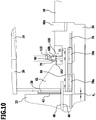
- FIG. 10 is shown a corresponding intermediate position in this movement.
- the encoder 90 is taken away by the actuator 52 until it reaches the first stop 100.
- the frictional fixation of the encoder 90 on the actuating element 52 causes a translation of the encoder 90 by the actuating element 52nd
- the sensor 110 and the encoder 90 are adapted to each other so that the sensor 110 provides a corresponding signal when the encoder 90 reaches the first stop 100.
- This signal is in particular a switching signal, which is transmitted to the control device 116 and in particular the travel path limiting device 118.
- This switching signal causes the control device 116, the drive 54 so controls that the displacement of the actuating element 52 is stopped with the movement away from the first clamping jaw 38 of the second jaw 40 away. As a result, the travel path d 2 is limited.
- the travel path d 2 is limited to a path of at most 6 mm. It is realized by a safety function, as required for example by DIN 13898. This minimizes the danger of crushing for an operator who inserts a workpiece 33 to be machined, since it is ensured that travel distances above a certain threshold, such as 6 mm, can not occur.
- the encoder 90 is pushed away at the enlargement of the opening width d 1 of the second stop 102 until it reaches the first stop 100. It is then switched off a further displacement of the actuating element 52. As in FIG. 10 is shown, thereby limiting the travel path d 2 realize in a simple manner.
- the first clamping jaw 38 is again moved in the direction of the second clamping jaw 40 in order to clamp the workpiece 33 between the first jaw 38 and the second jaw 40 for subsequent machining.
- the encoder 90 moves due to the frictional coupling to the actuator 52 with the actuator 52 from the first stop 100 away to the second stop 102.
- the actuator 52 can move further to the encoder 90; the encoder 90 is then translationally fixed with respect to the base 36. It then takes place the clamping of the workpiece 33rd
- an effective travel limit is achieved with a simple structural design to minimize the risk of crushing, especially when inserting a new workpiece to be machined 33.
- a limitation of the travel path d 2 to, for example, at most 6 mm can be achieved in a simple and effective manner.
Landscapes
- Engineering & Computer Science (AREA)
- Mechanical Engineering (AREA)
- Physics & Mathematics (AREA)
- Fluid Mechanics (AREA)
- General Engineering & Computer Science (AREA)
- Jigs For Machine Tools (AREA)
- Machine Tool Sensing Apparatuses (AREA)
Description
Die Erfindung betrifft eine Werkstück-Spannvorrichtung für eine Werkzeugmaschine.
Die Erfindung betrifft ferner eine Werkzeugmaschine, umfassend ein Maschinengestell, mindestens einen Werkstückhalter und mindestens einen Werkzeughalter.
Weiterhin betrifft die Erfindung ein Verfahren zum Einspannen eines Werkstücks an einer Werkstück-Spannvorrichtung, bei dem das Werkstück zwischen einer verschieblichen ersten Spannbacke und einer zweiten Spannbacke eingespannt wird. Aus der
Aus der
Aus der
Aus der
Der Erfindung liegt die Aufgabe zugrunde, eine Werkstück-Spannvorrichtung der eingangs genannten Art bereitzustellen, bei welcher auf konstruktiv einfache Weise ein Verfahrweg begrenzbar ist.The invention relates to a workpiece clamping device for a machine tool.
The invention further relates to a machine tool comprising a machine frame, at least one workpiece holder and at least one tool holder.
Furthermore, the invention relates to a method for clamping a workpiece on a workpiece clamping device, in which the workpiece between a displaceable first clamping jaw and a second clamping jaw is clamped. From the
From the
From the
From the
The invention has for its object to provide a workpiece clamping device of the type mentioned, in which in a structurally simple manner a travel is limited.
Diese Aufgabe wird bei der eingangs genannten Werkstück-Spannvorrichtung erfindungsgemäß dadurch gelöst, dass vorgesehen sind:This object is achieved in the aforementioned workpiece clamping device according to the invention that are provided:
Eine Basis, eine erste Spannbacke, welche relativ zu der Basis verschieblich ist, eine zweite Spannbacke, wobei ein Werkstück zwischen der ersten Spannbacke und der zweiten Spannbacke einspannbar ist, ein Antrieb, ein Betätigungselement, welches relativ zu der Basis verschieblich ist und welches an die erste Spannbacke gekoppelt ist, wobei eine Verschiebungsbewegung des Betätigungselements durch den Antrieb bewirkt ist und das Betätigungselement eine Verschiebung der ersten Spannbacke bewirkt, ein Geber, welcher an dem Betätigungselement angeordnet ist und mit dem Betätigungselement verschieblich ist und relativ zu dem Betätigungselement verschieblich ist, ein erster Anschlag und ein beabstandeter zweiter Anschlag für den Geber, zwischen welchen der Geber mit dem Betätigungselement verschieblich ist, wobei bei Anliegen des Gebers an dem ersten Anschlag oder an dem zweiten Anschlag der Geber relativ zu dem Betätigungselement verschieblich ist, und einen Sensor, durch welchen eine oder mehrere Positionen des Gebers detektierbar sind.A base, a first jaw which is displaceable relative to the base, a second jaw, wherein a workpiece between the first jaw and the second jaw is clamped, a drive, an actuating element which is displaceable relative to the base and which to the first clamping jaw is coupled, wherein a displacement movement of the actuating element is effected by the drive and the actuating element causes a displacement of the first clamping jaw, a transmitter, which is arranged on the actuating element and is displaceable with the actuating element and is displaceable relative to the actuating element, a first Stop and a second spaced stop for the encoder, between which the encoder is displaceable with the actuating element, wherein upon application of the encoder on the first stop or on the second stop the encoder is displaceable relative to the actuating element, and a sensor through which e ine or several positions of the encoder are detectable.
Die Position des Gebers ist ein Indikator für den Verfahrweg. Eine oder mehrere Positionen und insbesondere eine bestimmte Position des Gebers relativ zu dem ersten Anschlag lässt sich über den Sensor auf einfache Weise reproduzierbar detektieren.The position of the encoder is an indicator of the travel. One or more positions and in particular a specific position of the encoder relative to the first stop can be detected reproducibly via the sensor in a simple manner.
Es lässt sich auf einfache Weise ein Sensorsignal und insbesondere Schaltsignal generieren, durch welches der Verfahrweg begrenzbar ist.It can be generated in a simple manner, a sensor signal and in particular switching signal, by which the travel is limited.
Eine Begrenzung des Verfahrwegs als Differenz zwischen der Öffnungsweite zwischen der ersten Spannbacke und der zweiten Spannbacke und einer Werkstückbreite ist wünschenswert, um eine Quetschgefahr für einen Bediener, der ein neu zu bearbeitendes Werkstück einführt, zu minimieren.Limiting the travel distance as the difference between the opening width between the first jaw and the second jaw and a workpiece width is desirable in order to minimize the risk of crushing an operator who inserts a workpiece to be reworked.
Beispielsweise sollte nach der DIN-Norm 13898 der Verfahrweg nicht größer als 6 mm sein.For example, according to the DIN standard 13898 the travel should not be greater than 6 mm.
Bei der erfindungsgemäßen Lösung lässt sich einerseits der Geber mit dem Betätigungselement zwischen zwei ausgezeichneten Positionen, nämlich zwischen dem ersten Anschlag und dem zweiten Anschlag mittels des Betätigungselements bewegen. Er lässt sich bei Anliegen an dem ersten Anschlag beziehungsweise dem zweiten Anschlag translationsfest halten, da grundsätzlich eine relative Verschieblichkeit des Betätigungselements zu dem Geber möglich ist. Es lässt sich dadurch wiederum ein sicheres Sensorsignal und insbesondere Schaltsignal bei Erreichen des ersten Anschlags generieren, um insbesondere eine weitere Wegbewegung der ersten Spannbacke von der zweiten Spannbacke zu stoppen.In the solution according to the invention, on the one hand, the encoder with the actuating element can be moved between two excellent positions, namely between the first stop and the second stop by means of the actuating element. It can be hold off translation when concerns on the first stop or the second stop, since in principle a relative displaceability of the actuating element to the encoder is possible. In turn, it is thereby possible to generate a reliable sensor signal and, in particular, a switching signal upon reaching the first stop, in order in particular to stop further movement of the first clamping jaw away from the second clamping jaw.
Es wird dadurch auf einfache und sichere Weise eine reproduzierbare, genaue Verfahrwegbegrenzung erreicht.It is achieved in a simple and secure way a reproducible, accurate Trafahrwegbegrenzung.
Diese Verfahrwegbegrenzung lässt sich mit konstruktiv einfachem Aufbau erreichen, wobei insbesondere ein Einspannungsvorgang des Werkstücks zwischen der ersten Spannbacke und der zweiten Spannbacke minimal beeinflusst wird.This Verfahrwegbegrenzung can be achieved with a structurally simple structure, in particular, a clamping operation of the workpiece between the first clamping jaw and the second jaw is minimally affected.
Die Werkstück-Spannvorrichtung kann grundsätzlich beliebig im Raum ausgerichtet sein. Sie kann beispielsweise (bezogen auf die Schwerkraftrichtung) horizontal ausgerichtet sein oder vertikal ausgerichtet sein oder auch zwischen einer vertikalen oder horizontalen Stellung ausgerichtet sein.The workpiece clamping device can basically be aligned arbitrarily in space. For example, it may be horizontally oriented (in relation to the direction of gravity), or vertically aligned, or even aligned between a vertical or horizontal position.
Das Betätigungselement ist an die erste Spannbacke gekoppelt. Es ist grundsätzlich möglich, dass das Betätigungselement nicht an die zweite Spannbacke gekoppelt ist oder an die zweite Spannbacke gekoppelt ist. Im letzteren Falle ist das Betätigungselement beispielsweise als Links-Rechts-Spindel ausgebildet beziehungsweise umfasst eine solche. Eine derartige Werkstück-Spannvorrichtung ist vorteilhaft für die Einspannung von Rundmaterialien.The actuating element is coupled to the first clamping jaw. It is in principle possible that the actuating element is not coupled to the second clamping jaw or is coupled to the second clamping jaw. In the latter case, the actuating element is designed, for example, as a left-right spindle or comprises such. Such a workpiece clamping device is advantageous for the clamping of round materials.
Günstig ist es, wenn der erste Anschlag und der zweite Anschlag translationsfest zu der Basis angeordnet sind (wobei grundsätzlich eine festgestellte Einstellbarkeit der Position zu der Basis möglich ist). Es werden dadurch gewissermaßen Referenzpunkte gesetzt, wobei insbesondere der erste Anschlag ein Referenzpunkt für die Begrenzung des Verfahrwegs ist. Durch den ersten Anschlag und den zweiten Anschlag bewegt sich der Geber reproduzierbar nur in dem Bereich zwischen dem ersten Anschlag und dem zweiten Anschlag. Es wird dadurch eine hohe Reproduzierbarkeit der Verfahrwegbegrenzung erreicht.It is advantageous if the first stop and the second stop are disposed in a manner fixed in a translation-proof manner to the base (basically a determined adjustability of the position relative to the base being possible). As a result, reference points are thereby set, in which case in particular the first stop is a reference point for limiting the travel path. By the first stop and the second stop, the encoder moves reproducibly only in the area between the first stop and the second stop. It is achieved by a high reproducibility of the travel limit.
Günstigerweise ist eine Abstandsrichtung zwischen dem ersten Anschlag und dem zweiten Anschlag parallel zu einer Verschiebungsrichtung des Betätigungselements. Dadurch lässt sich eine Verfahrwegbegrenzung auf konstruktiv einfache Weise erreichen.Conveniently, a distance direction between the first stop and the second stop is parallel to a displacement direction of the actuating element. As a result, a travel limit can be achieved in a structurally simple manner.
Bei einem Ausführungsbeispiel sind der erste Anschlag und der zweite Anschlag durch Innenseiten eines Gehäuses gebildet, in welchem ein Sensorkopf des Sensors angeordnet ist. Das Gehäuse kann dazu verwendet werden, den Sensorkopf zu schützen. Ferner kann dadurch der Geber geschützt werden. Das Gehäuse kann auch dazu verwendet werden, um eine Führung für das Betätigungselement relativ zu der Basis zu realisieren. Das Gehäuse kann geschlossen sein oder an einer oder mehreren Seiten offen sein.In one embodiment, the first stop and the second stop are formed by inner sides of a housing in which a sensor head of the sensor is arranged. The housing can be used to protect the sensor head. Furthermore, this can protect the encoder. The housing may also be used to provide a guide for the actuator relative to the base. The housing may be closed or open on one or more sides.
Es ist dann günstig, wenn der Geber in dem Gehäuse positioniert ist. Dadurch lässt sich dieser geschützt unterbringen und es ist auf einfache Weise eine Bewegung zwischen dem ersten Anschlag und dem zweiten Anschlag realisierbar.It is advantageous if the encoder is positioned in the housing. As a result, it can be accommodated protected and it is easy to implement a movement between the first stop and the second stop.
Günstig ist es, wenn der Geber auf dem Betätigungselement sitzt. Dadurch lässt sich auf einfache Weise eine Mitnahme des Gebers mit dem Betätigungselement für eine Beweglichkeit zwischen dem ersten Anschlag und dem zweiten Anschlage erreichen.It is favorable if the encoder is seated on the actuating element. As a result, it is possible in a simple manner to achieve entrainment of the transmitter with the actuating element for mobility between the first stop and the second stop.
Es ist dann besonders vorteilhaft, wenn der Geber ein Ringelement aufweist oder durch ein Ringelement gebildet ist, wobei das Betätigungselement durch eine Ringöffnung durchgetaucht ist. Es lässt sich dadurch auf einfache Weise eine Fixierung des Gebers an dem Betätigungselement erreichen. Die Fixierung lässt sich auf konstruktiv einfache Weise so ausbilden, dass zwischen dem ersten Anschlag und dem zweiten Anschlag der Geber mit dem Betätigungselement verschieblich ist, das heißt, dass der Geber translationsfest zu dem Betätigungselement ist. Es lässt sich auch auf einfache Weise erreichen, dass bei Anliegen an dem ersten Anschlag beziehungsweise dem zweiten Anschlag der Geber translationsfest zu der Basis ist, das heißt grundsätzlich das Betätigungselement relativ zu dem Geber verschieblich ist.It is particularly advantageous if the encoder has a ring element or is formed by a ring element, wherein the actuating element is immersed through an annular opening. This makes it easy to achieve a fixation of the encoder on the actuator. The fixation can be designed in a structurally simple way so that between the first stop and the second stop the encoder is displaceable with the actuating element, that is, that the encoder is translation-fixed to the actuating element. It can also be achieved in a simple manner that when concerns on the first stop or the second stop the transmitter is translation-fixed to the base, that is, in principle, the actuating element is displaceable relative to the encoder.
Insbesondere ist es vorgesehen, dass der Geber kraftschlüssig an dem Betätigungselement sitzt. Es lässt sich dadurch auf konstruktiv einfache Weise erreichen, dass der Geber für eine Verschiebung zwischen dem ersten Anschlag und dem zweiten Anschlag durch das Betätigungselement mitgenommen wird und bei Anliegen an dem ersten Anschlag beziehungsweise dem zweiten Anschlag nicht mitgenommen wird, sondern translationsfest zu der Basis ist.In particular, it is provided that the encoder sits non-positively on the actuating element. It can thus be achieved in a structurally simple manner that the encoder is taken for a shift between the first stop and the second stop by the actuating element and not taken with concerns on the first stop or the second stop, but is translation-fixed to the base ,
Eine kraftschlüssige Fixierung lässt sich auf einfache Weise erreichen, wenn der Geber ein elastisches Element aufweist, über welches der Geber an dem Betätigungselement sitzt. Das elastische Element ist ein Stellelement und insbesondere ein Stellring, welches für eine kraftschlüssige Fixierung sorgt. Über das elastische Element lässt sich durch Vergrößerung der Normalkraft eine erhöhte (Haft-)Reibungskraft für die kraftschlüssige Fixierung erreichen.A frictional fixation can be achieved in a simple manner if the encoder has an elastic element, via which the encoder is seated on the actuating element. The elastic element is an adjusting element and in particular a setting ring, which ensures a force-locking fixation. By increasing the normal force, an increased (adhesive) frictional force for the non-positive fixation can be achieved via the elastic element.
Bei einem fertigungstechnisch und konstruktiv einfachem Ausführungsbeispiel ist das elastische Element ein O-Ring.In a manufacturing technology and structurally simple embodiment, the elastic element is an O-ring.
Günstigerweise weist der Geber einen oder mehrere Bereiche auf, bezüglich welchen der Sensor sensitiv ist. Dadurch lässt sich eine definierte Position beziehungsweise lassen sich mehrere definierte Positionen des Gebers durch den Sensor detektieren.Conveniently, the transmitter has one or more regions with respect to which the sensor is sensitive. This allows a defined position or can be more defined positions of the encoder detected by the sensor.
Insbesondere ist der Sensor ein Näherungssensor oder Abstandssensor oder Kontaktschalter. Es lässt sich dadurch eine Position oder mehrere Positionen und insbesondere eine oder mehrere ausgezeichnete Positionen des Gebers relativ zu dem Sensor detektieren. Der Sensor kann beispielsweise eine oder mehrere bestimmte Positionen des Gebers berührungslos ermitteln oder es kann ein entsprechendes Signal und insbesondere Schaltsignal erzeugt werden, wenn der Geber den Sensor, welcher dann insbesondere als Kontaktschalter beziehungsweise Mikroschalter ausgebildet ist, mechanisch kontaktiert.In particular, the sensor is a proximity sensor or distance sensor or contact switch. It can thereby detect one or more positions and in particular one or more excellent positions of the transmitter relative to the sensor. The sensor can detect, for example, one or more specific positions of the encoder without contact, or a corresponding signal and, in particular, a switching signal can be generated if the transmitter mechanically contacts the sensor, which is then designed in particular as a contact switch or microswitch.
Insbesondere ist der Sensor ein berührungsloser Sensor. Dadurch wird beispielsweise durch die erfindungsgemäße Verfahrwegbegrenzung eine Werkstückeinspannung minimal beeinflusst.In particular, the sensor is a non-contact sensor. As a result, a clamping of the workpiece is minimally influenced, for example, by the travel limiting according to the invention.
Bei einem Ausführungsbeispiel ist der Sensor ein induktiver Sensor. Dadurch kann beispielsweise der Geber auf einfache Weise als Metallelement ausgebildet werden, wobei insbesondere eine oder mehrere ausgezeichnete Positionen des Gebers relativ zu dem Sensor auf einfache und berührungslose Weise feststellbar sind.In one embodiment, the sensor is an inductive sensor. As a result, for example, the encoder can be formed in a simple manner as a metal element, wherein in particular one or more excellent positions of the encoder relative to the sensor in a simple and non-contact manner can be determined.
Insbesondere generiert der Sensor ein Schaltsignal, wenn der Geber den ersten Anschlag erreicht, wobei der erste Anschlag weiter entfernt von der ersten Spannbacke ist als der zweite Anschlag. Das Schaltsignal kann dabei dazu benutzt werden, um eine Weiterbewegung der ersten Spannbacke von der zweiten Spannbacke weg zu stoppen. Dadurch lässt sich eine effektive Verfahrwegbegrenzung erreichen.In particular, the sensor generates a switching signal when the encoder reaches the first stop, wherein the first stop is farther away from the first clamping jaw than the second stop. The switching signal can be used to stop further movement of the first clamping jaw away from the second clamping jaw. As a result, an effective travel limit can be achieved.
Günstig ist es, wenn eine Steuerungseinrichtung vorgesehen ist, welche signalwirksam an den Sensor gekoppelt ist und welche den Antrieb ansteuert. Dadurch lässt sich über ein Sensorsignal eine Position des Betätigungselements einstellen und insbesondere lässt sich eine Wegbewegung der ersten Spannbacke von der zweiten Spannbacke stoppen, wenn der Sensor ein entsprechendes Signal bereitstellt, welches anzeigt, dass der Geber an dem ersten Anschlag anliegt.It is advantageous if a control device is provided which is signal-effectively coupled to the sensor and which drives the drive. This allows a position of the actuating element via a sensor signal set and in particular can be a movement away the first jaw from the second jaw stop when the sensor provides a corresponding signal indicating that the encoder is applied to the first stop.
Insbesondere stoppt die Steuerungseinrichtung eine Wegbewegung der ersten Spannbacke von der zweiten Spannbacke, wenn der Sensor ein Schaltsignal für das Erreichen des ersten Anschlags durch den Geber bereitstellt. Dadurch lässt sich auf einfache Weise eine effektive Verfahrwegbegrenzung erreichen, um insbesondere eine Quetschgefahr für einen Bediener zu minimieren.In particular, the control device stops a movement of the first clamping jaw away from the second clamping jaw when the sensor provides a switching signal for reaching the first stop by the encoder. As a result, can be achieved in a simple manner an effective Verfahrwegbegrenzung, in particular to minimize a risk of crushing for an operator.
Ganz besonders vorteilhaft ist es, wenn die Steuerungseinrichtung eine Verfahrweg-Begrenzungseinrichtung aufweist, welche eine Öffnungsweise zwischen der ersten Spannbacke und der zweiten Spannbacke begrenzt, wobei ein Verfahrweg die Öffnungsweite abzüglich einer Werkstückbreite ist. Es lässt sich dadurch die Quetschgefahr minimieren.It is particularly advantageous if the control device has a travel path limiting device which limits an opening manner between the first clamping jaw and the second clamping jaw, wherein a travel distance is the opening width minus a workpiece width. It can thereby minimize the risk of crushing.
Insbesondere ist der Verfahrweg auf höchstens 6 mm begrenzt, um eine einschlägige DIN-Norm zu erfüllen.In particular, the travel is limited to a maximum of 6 mm to meet a relevant DIN standard.
Es kann vorgesehen sein, dass mindestens eine der vorliegenden Größen feststellbar einstellbar ist: (i) Position des ersten Anschlags; (ii) Position des zweiten Anschlags; (iii) Abstand zwischen dem ersten Anschlag und dem zweiten Anschlag. Es lässt sich dadurch die Werkstück-Spannvorrichtung an unterschiedliche Werkstückbreiten anpassen.It can be provided that at least one of the present variables can be set in a determinable manner: (i) position of the first stop; (ii) position of the second stop; (iii) distance between the first stop and the second stop. It can thereby adjust the workpiece clamping device to different workpiece widths.
Ganz besonders vorteilhaft ist es, wenn der erste Anschlag weiter entfernt von der ersten Spannbacke ist als der zweite Anschlag, wobei, wenn die erste Spannbacke auf die zweite Spannbacke zubewegt ist, der Geber zunächst in Richtung des zweiten Anschlags mitgenommen mit dem Betätigungselement verschoben wird, bis er an dem zweiten Anschlag anliegt, und dann der Geber relativ zu dem zweiten Anschlag nicht weiter verschoben wird, und, wenn die erste Spannbacke von der zweiten Spannbacke weg bewegt ist, der Geber mitgenommen mit dem Betätigungselement in Richtung des ersten Anschlags verschoben wird, bis er an diesem anliegt und bei Weiterbewegung des Betätigungselements nicht weiter verschoben wird. Es wird dadurch eine Beweglichkeit des Gebers zwischen dem ersten Anschlag und dem zweiten Anschlag realisiert, wobei der entsprechende Bewegungsweg fest zu der Basis ist. Es lässt sich wiederum durch Überwachung mittels des Sensors, ob der Geber an dem ersten Anschlag anliegt, und dann entsprechende Bereitstellung eines Signals und insbesondere Schaltsignals eine Verfahrwegbegrenzung erreichen. Diese Verfahrwegbegrenzung lässt sich mit relativ geringem konstruktivem Aufwand realisieren und sie weist eine hohe Reproduzierbarkeit auf.It is particularly advantageous if the first stop is farther away from the first clamping jaw than the second stop, wherein, when the first clamping jaw is moved toward the second clamping jaw, the encoder is first moved in the direction of the second stop, moved with the actuating element, until it abuts the second stop, and then the encoder is not further displaced relative to the second stop, and, when the first jaw is moved away from the second jaw, the encoder taken along with the actuating element in the direction of the first stop is moved until it rests against this and is not further displaced upon further movement of the actuating element. It is realized by a mobility of the encoder between the first stop and the second stop, wherein the corresponding movement path is fixed to the base. It can in turn be achieved by monitoring by means of the sensor, whether the encoder is applied to the first stop, and then corresponding provision of a signal and in particular switching signal to a travel limit. This travel limit can be realized with relatively little design effort and it has a high reproducibility.
Der Antrieb ist beispielsweise ein hydraulischer, pneumatischer oder motorischer Antrieb.The drive is for example a hydraulic, pneumatic or motor drive.
Bei einem Ausführungsbeispiel ist der Antrieb ein hydraulischer pneumatischer Antrieb und das Betätigungselement ist Teil einer Kolbeneinheit und ist insbesondere eine Kolbenstange.In one embodiment, the drive is a hydraulic pneumatic drive and the actuator is part of a piston unit and is in particular a piston rod.
Ganz besonders vorteilhaft ist es, wenn durch den Antrieb eine Abstandsposition zwischen der ersten Spannbacke und der zweiten Spannbacke feststellbar ist. Der Antrieb bewirkt dann nicht nur eine Verschiebungsbewegung des Betätigungselements, sondern er legt eine bestimmte Position des Betätigungselements auch fest.It is particularly advantageous if a distance position between the first clamping jaw and the second clamping jaw can be determined by the drive. The drive then not only causes a displacement movement of the actuating element, but he also determines a certain position of the actuating element.
Erfindungsgemäß wird eine Werkzeugmaschine der eingangs genannten Art bereitgestellt, bei der der mindestens eine Werkstückhalter eine erfindungsgemäße Werkstück-Spannvorrichtung ist oder umfasst.According to the invention, a machine tool of the aforementioned type is provided in which the at least one workpiece holder is or comprises a workpiece clamping device according to the invention.
Insbesondere ist die Basis Teil des Maschinengestells oder ist fest an diesem angeordnet. Dadurch ergibt sich ein einfacher konstruktiver Aufbau.In particular, the base is part of the machine frame or is fixedly arranged on this. This results in a simple structural design.
Bei einem Ausführungsbeispiel ist die Werkzeugmaschine als Sägemaschine und insbesondere Bandsägemaschine ausgebildet, wobei ein Werkzeug ein Sägewerkzeug und insbesondere ein Sägeband ist. Die erfindungsgemäße Werkstück-Spannvorrichtung lässt sich auf effektive Weise bei einer Sägemaschine und insbesondere Bandsägemaschine einsetzen.In one embodiment, the machine tool is designed as a sawing machine and in particular band saw machine, wherein a tool a Sawing tool and in particular a saw blade is. The workpiece clamping device according to the invention can be used effectively in a sawing machine and in particular band saw machine.
Der Erfindung liegt ferner die Aufgabe zugrunde, ein Verfahren der eingangs genannten Art bereitzustellen, bei dem eine effektive Verfahrwegbegrenzung erreicht ist.The invention is further based on the object to provide a method of the type mentioned, in which an effective Verfahrwegbegrenzung is reached.
Diese Aufgabe wird bei dem eingangs genannten Verfahren erfindungsgemäß dadurch gelöst, dass das Werkstück zwischen einer verschieblichen ersten Spannbacke und einer zweiten Spannbacke eingespannt wird, wobei die erste Spannbacke mittels eines Betätigungselements verschoben wird und an dem Betätigungselement ein Geber angeordnet ist, für den eine oder mehrere bestimmte Positionen durch einen Sensor erfasst werden, und bei dem zwischen einem ersten Anschlag und einem zweiten Anschlag der Geber durch das Betätigungselement mitgenommen wird und der Geber bei Anliegen an dem ersten Anschlag oder bei Anliegen an dem zweiten Anschlag unverschieblich bezüglich einer Basis ist und relativ zu dem Betätigungselement verschieblich ist.This object is achieved according to the invention in the above-mentioned method in that the workpiece is clamped between a displaceable first clamping jaw and a second clamping jaw, wherein the first clamping jaw is displaced by means of an actuating element and an encoder is arranged on the actuating element, for the one or more certain positions are detected by a sensor, and wherein between a first stop and a second stop the encoder is entrained by the actuating element and the encoder when abutting the first stop or abutment against the second stop is immovable relative to a base and relative to the actuating element is displaceable.
Das erfindungsgemäße Verfahren weist die bereits im Zusammenhang mit der erfindungsgemäßen Werkstück-Spannvorrichtung erläuterten Vorteile auf.The method according to the invention has the advantages already explained in connection with the workpiece clamping device according to the invention.
Weitere vorteilhafte Ausgestaltungen des erfindungsgemäßen Verfahrens wurden bereits im Zusammenhang mit der erfindungsgemäßen Werkstück-Spannvorrichtung erläutert.Further advantageous embodiments of the method according to the invention have already been explained in connection with the workpiece clamping device according to the invention.
Insbesondere wird bei Erreichen des ersten Anschlags durch den Geber, wobei der erste Anschlag weiter entfernt von der ersten Spannbacke ist als der zweite Anschlag, durch den Sensor ein Schaltsignal erzeugt. Dieses Schaltsignal kann dazu verwendet werden, eine weitere Wegbewegung der ersten Spannbacke von der zweiten Spannbacke zu stoppen.In particular, when the first stop is reached by the encoder, wherein the first stop is farther away from the first clamping jaw than the second stop, a switching signal is generated by the sensor. This switching signal can be used to stop further movement of the first jaw away from the second jaw.
Vorteilhafterweise ist eine Steuerungseinrichtung vorgesehen, welche aufgrund des Schaltsignals des Sensors eine weitere Auseinanderbewegung der ersten Spannbacke von der zweiten Spannbacke weg stoppt, um einen Verfahrweg zu begrenzen.Advantageously, a control device is provided which, due to the switching signal of the sensor, stops further movement apart of the first clamping jaw away from the second clamping jaw in order to limit a travel path.
Das erfindungsgemäße Verfahren lässt sich an der erfindungsgemäßen Werkstück-Spannvorrichtung durchführen.The method according to the invention can be carried out on the workpiece clamping device according to the invention.
Die erfindungsgemäße Werkstück-Spannvorrichtung lässt sich mit dem erfindungsgemäßen Verfahren betreiben.The workpiece clamping device according to the invention can be operated with the method according to the invention.
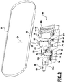
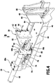
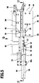
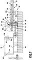
Die nachfolgende Beschreibung bevorzugter Ausführungsformen dient im Zusammenhang mit den Zeichnungen der näheren Erläuterung der Erfindung. Es zeigen:
- Figur 1
- eine schematische Darstellung einer Bandsägemaschine als Ausführungsbeispiel einer Werkzeugmaschine;
- Figur 2
- eine perspektivische Teildarstellung der Werkzeugmaschine gemäß
Figur 1 ; - Figur 3
- eine Ansicht der Werkzeugmaschine gemäß
Figur 1 in der Richtung A; - Figur 4
- eine perspektivische Darstellung eines Ausführungsbeispiels einer Werkstück-Spannvorrichtung;
- Figur 5
- eine Ansicht der Werkstück-Spannvorrichtung gemäß
Figur 4 in der Richtung B (Draufsicht); - Figur 6
- eine Explosionsdarstellung der Werkstück-Spannvorrichtung gemäß
Figur 4 ; - Figur 7
- eine Schnittansicht längs der Linie 7-7 gemäß
Figur 5 ; - Figur 8
- eine vergrößerte Darstellung des Bereichs C in
Figur 7 ; - Figur 9
- eine vergrößerte Teilansicht der Werkstück-Spannvorrichtung in der Richtung D gemäß
Figur 5 bei einer ersten Stellung eines Betätigungselements; und Figur 10- die gleiche Ansicht wie in
Figur 9 bei einer anderen Stellung des Betätigungselements.
- FIG. 1
- a schematic representation of a band saw machine as an embodiment of a machine tool;
- FIG. 2
- a partial perspective view of the machine tool according to
FIG. 1 ; - FIG. 3
- a view of the machine tool according to
FIG. 1 in direction A; - FIG. 4
- a perspective view of an embodiment of a workpiece clamping device;
- FIG. 5
- a view of the workpiece clamping device according to
FIG. 4 in the direction B (top view); - FIG. 6
- an exploded view of the workpiece clamping device according to
FIG. 4 ; - FIG. 7
- a sectional view taken along the line 7-7 according to
FIG. 5 ; - FIG. 8
- an enlarged view of the area C in
FIG. 7 ; - FIG. 9
- an enlarged partial view of the workpiece clamping device in the direction D according to
FIG. 5 at a first position of an actuating element; and - FIG. 10
- the same view as in
FIG. 9 at a different position of the actuating element.
Ein Ausführungsbeispiel einer erfindungsgemäßen Werkzeugmaschine, welche in
Die erste Rolle 18 und die zweite Rolle 20 sind an einem Schlitten 22 gehalten. Dieser Schlitten 22 ist relativ zu dem Maschinengestell 12 höhenbeweglich und insbesondere höhenverschieblich. Eine entsprechende Verschiebungsrichtung ist in
Dem Werkzeughalter 14 ist ein erstes Ausrichtelement 26 und ein beabstandetes zweites Ausrichtelement 28 zugeordnet. Zwischen dem ersten Ausrichtelement 26 und dem zweiten Ausrichtelement 28 ist ein Bereich 30 des Sägebands 16 derart ausgerichtet, dass es ein Werkstück 33 bei Zubewegung auf das Maschinengestell 12 hin durchsägen kann.The
An dem Maschinengestell 12 ist ferner ein Werkstückhalter 32 angeordnet. Erfindungsgemäß umfasst der Werkstückhalter 32 eine Werkstück-Spannvorrichtung 34 beziehungsweise ist als solche ausgebildet.On the
Die Werkstück-Spannvorrichtung 34 hat eine Basis 36, welche fest mit dem Maschinengestell 12 verbunden ist oder Teil des Maschinengestells 12 ist.The
An der Basis 36 ist eine erste Spannbacke 38 angeordnet. Es ist ferner eine zu der ersten Spannbacke 38 beabstandete zweite Spannbacke 40 vorgesehen.At the
Die erste Spannbacke 38 weist eine erste Spannfläche 42 auf. Die zweite Spannbacke 40 weist eine zweite Spannfläche 44 auf. Die erste Spannfläche 42 und die zweite Spannfläche 44 sind insbesondere Ebenen, wobei vorzugsweise die erste Spannfläche 42 und die zweite Spannfläche 44 parallel zueinander ausgerichtet sind. Das Werkstück 33 lässt sich zwischen der ersten Spannfläche 42 und der zweiten Spannfläche 44 einspannen, um es für einen Bearbeitungsvorgang mit dem Sägeband 16 zu fixieren.The
Die Werkstück-Spannvorrichtung 34 weist ferner ein Auflageelement 46 auf, auf welches das Werkstück 33 zur Bearbeitung auflegbar ist. Das Auflageelement 46 hat eine Auflagefläche 48, welche insbesondere eben ausgebildet ist.The
Die erste Spannfläche 42 und die zweite Spannfläche 44 sind quer und insbesondere senkrecht zu der Auflagefläche 48 orientiert.The
Das Auflageelement 46 ist fest mit der Basis 36 verbunden oder Teil der Basis 36. Die zweite Spannbacke 40 ist fest mit der Basis 36 verbunden. Die erste Spannbacke 38 ist verschieblich in einer Verschiebungsrichtung 50 relativ zu der Basis 30. Die Verschiebungsrichtung 50 liegt dabei insbesondere quer zu der ersten Spannfläche 42 beziehungsweise der zweiten Spannfläche 44 und liegt insbesondere senkrecht zu der ersten Spannfläche 42 beziehungsweise der zweiten Spannfläche 44. Weiterhin liegt die Verschiebungsrichtung 50 insbesondere parallel zu der Auflagefläche 48.The
Durch die Verschieblichkeit der ersten Spannbacke 38 relativ zu der zweiten Spannbacke 40 ist eine Öffnungsweite d1 als Abstand zwischen der ersten Spannbacke 38 und der zweiten Spannbacke 40 feststellbar einstellbar (vgl. beispielsweise
An der ersten Spannbacke 38 ist ein Betätigungselement 52 fixiert. Das Betätigungselement 52 ist in der Verschiebungsrichtung 50 verschieblich und insbesondere linear verschieblich.At the
Dem Betätigungselement 52 ist ein Antrieb 54 zugeordnet. Der Antrieb 54 ist beabstandet zu der ersten Spannbacke 38 und das Betätigungselement 52 sorgt für die Kraftübertragung von dem Antrieb 54 auf die erste Spannbacke 38.The
Dieser Antrieb 54 bewirkt eine Verschiebungsbetätigung des Betätigungselements 52, wobei über den Antrieb 54 auch eine Verschiebungsposition des Betätigungselements 52 einstellbar und festlegbar ist. Dadurch lässt sich insbesondere eine Spannposition der ersten Spannbacke 38 zur Klemmfixierung eines Werkstücks 33 zwischen der ersten Spannbacke 38 und der zweiten Spannbacke 40 für eine Werkstückbearbeitung festlegen.This
Bei einem Ausführungsbeispiel ist das Betätigungselement 52 eine Stange oder Spindel 56 (vgl. beispielsweise
Der Antrieb 54 ist ein hydraulischer Antrieb, wobei durch entsprechende hydraulische Beaufschlagung des Kolbens 62 in dem Zylinder 60 eine lineare Verschiebungsbewegung und Verschiebungsposition des Betätigungselements 52 und damit der ersten Spannbacke 38 einstellbar ist.The
Die Kolbeneinheit 58 weist dazu eine entsprechende Verschiebungs-Lagereinrichtung 64 für die Spindel 56 auf.The
An der Basis 36 ist eine Halteeinrichtung 66 gehalten, welche den Zylinder 60 translationsfest an der Basis 36 hält.At the
Bei einem ersten Ausführungsbeispiel umfasst die Halteeinrichtung 66 ein erstes Halteelement 68a und ein beabstandetes zweites Halteelement 68b, welche an der Basis 36 fixiert sind. Über diese ist der Zylinder 60 in einem Höhenabstand zu der Basis 36 fixiert. Das Betätigungselement 52 ist dann in einem Höhenabstand zu der Basis 36 relativ zu der Basis 36 in der Verschiebungsrichtung 50 (welches auch die Verschiebungsrichtung der ersten Spannbacke 38 ist) verschieblich.In a first embodiment, the holding
Das zweite Halteelement 68b ist als Gehäuse 70 ausgebildet. Dieses Gehäuse 70 weist einen Innenraum 72 auf, welcher teilweise oder vollständig geschlossen ist.The
Es ist auch möglich, dass der Antrieb 54 beispielsweise ein pneumatischer Antrieb ist oder ein motorischer Antrieb oder ein elektromotorischer Antrieb ist. Der Antrieb 54 bewirkt eine Verschiebungsbewegung und Positionsfeststellung des Betätigungselements 52 und damit der ersten Spannbacke 38.It is also possible that the
Der ersten Spannbacke 38 ist eine Führungseinrichtung 74 zugeordnet (vgl. beispielsweise
Die Führungseinrichtung 74 ist insbesondere als Gleitführung ausgebildet.The
Bei einem Ausführungsbeispiel umfasst die Führungseinrichtung 74 eine Leiste 76, welche an der Basis 36 angeordnet ist.In one embodiment, the
An dieser Leiste 76 sitzen ein oder mehrere Gleitschuhe. Bei dem gezeigten Ausführungsbeispiel sitzen an der Leiste 76 beabstandete Gleitschuhe 78a, 78b.On this
Die erste Spannbacke 38 weist eine Halteplatte 80 auf. Die Gleitschuhe 78a, 78b sind an der Halteplatte 80 fixiert.The
Die Gleitschuhe 78a, 78b liegen dabei insbesondere bezogen auf eine Höhenrichtung der Basis 36 unterhalb des Betätigungselements 52.In this case, the sliding
An der Halteplatte 80 ist eine Strebe 82 angeordnet, welche beispielsweise Trapezform hat. An der Strebe 82 wiederum sitzt ein entsprechendes Element mit der ersten Spannfläche 42.On the holding
Die Strebe 82 ist plattenförmig ausgebildet, wobei sie quer zu der ersten Spannfläche 42 orientiert ist.The
In dem Auflageelement 46 ist eine durchgehende Nut 84 gebildet. Die Strebe 82 ist durch die Nut 84 durchgetaucht, so dass die erste Spannfläche 42 oberhalb der Auflagefläche 48 liegt. Die Halteplatte 80 ist unterhalb des Auflageelements 46 positioniert.In the
Die erste Spannfläche 42 weist eine solche Breite auf, dass sie beabstandet zu dem Sägeband 16 ist, wenn dieses in der Richtung 24 auf das Maschinengestell 12 zum Durchsägen des Werkstücks 33 bewegt wird.The
Es kann dabei vorgesehen sein, dass an der ersten Spannbacke 38 eine Führungsleiste 86 angeordnet ist, an welcher das Sägeband 16 mit einer Außenseite entlang gleitbar ist.It may be provided that on the
Bei einem Ausführungsbeispiel weist die zweite Spannbacke 40 eine durchgehende Nut 88 auf, welche quer und insbesondere senkrecht zu der Nut 84 orientiert ist. Durch diese Nut 88 ist das Sägeband 16 durchtauchbar.In one embodiment, the
Auf dem Betätigungselement 52 sitzt in dem Innenraum 72 des Gehäuses 70 ein Geber 90 (vgl. die
Beispielsweise ist die Ringöffnung 94 im Querschnitt kreisförmig, wenn das Betätigungselement 52 mindestens in dem Bereich, in dem der Geber 90 sitzt, eine zylindrische Außengestalt hat.For example, the
Das Betätigungselement 52 ist durch die Ringöffnung 94 durchgetaucht und der Geber 90 sitzt auf dem Betätigungselement 52.The
Der Geber 90 umfasst ferner ein Stellelement 96, welches insbesondere als Stellring ausgebildet ist.The
Bei einem Ausführungsbeispiel weist das Ringelement 92 zu der Ringöffnung 94 eine Nut 98 auf.In one embodiment, the
Bei einem Ausführungsbeispiel ist die Nut 98 eine Ringnut.In one embodiment, the
In dieser Nut 98 sitzt das Stellelement 96 und insbesondere ein Stellring.In this
Das Stellelement 96 ist insbesondere ein elastisches Element. Beispielsweise ist das Stellelement 96 durch einen O-Ring ausgebildet.The adjusting
Über das Stellelement 96 sitzt der Geber 90 kraftschlüssig auf dem Betätigungselement 52 derart, dass einerseits der Geber 90 bei einer Bewegung des Betätigungselements 52 mit diesem mitgenommen wird und eine Verschieblichkeit in der Verschiebungsrichtung 50 des Gebers 90 erfolgt, und andererseits, wie unten noch näher beschrieben wird, unter bestimmten Bedingungen der Geber 90 relativ zu der Basis 36 festhaltbar ist und dann eine relative Verschiebung des Betätigungselements 52 zu dem Geber 90 erfolgen kann.About the
Die Werkstück-Spannvorrichtung 34 weist einen ersten Anschlag 100 und einen beabstandeten zweiten Anschlag 102 für den Geber 90 auf (vgl. beispielsweise
Bei einem Ausführungsbeispiel ist der erste Anschlag 100 durch eine erste Innenseite 104 des Gehäuses 70 gebildet. Der zweite Anschlag 102 ist durch eine gegenüberliegende zweite Innenseite 106 des Gehäuses 70 gebildet.In one embodiment, the
Zwischen dem ersten Anschlag 100 und dem zweiten Anschlag 102 ist der Geber 90 verschieblich.Between the
Der erste Anschlag 100 und der zweite Anschlag 102 sind translationsfest zu der Basis 36.The
Bei einem Ausführungsbeispiel sind eine Position des ersten Anschlags 100 und/oder eine Position des zweiten Anschlags 102 in der Verschiebungsrichtung 50 relativ zu der Basis 36 feststellbar einstellbar. Dies ist in
Es ist grundsätzlich auch möglich, dass der erste Anschlag 100 und der zweite Anschlag 102 nicht einstellbar fest zu der Basis 36 angeordnet sind.In principle, it is also possible for the
Dem Geber 90 ist ein Sensor 110 zugeordnet. Dieser Sensor 110 ist mindestens teilweise in dem Innenraum 72 des Gehäuses 70 angeordnet. Insbesondere ist ein Sensorkopf 112, welcher ein oder mehrere bezüglich des Gebers 90 sensitive Elemente umfasst, geschützt in dem Innenraum 72 des Gehäuses 70 angeordnet.The
Der Sensor 110 erfasst eine oder mehrere bestimmte Positionen des Gebers 90.The
Beispielsweise ist der Sensorkopf 112 als berührungsloser Näherungssensor beziehungsweise Abstandssensor ausgebildet.For example, the
Bei einem Ausführungsbeispiel ist der Sensor 110 als Schaltsensor ausgebildet, welcher ein Schaltsignal liefert, wenn der Geber 70 an dem ersten Anschlag 100 anliegt.In one embodiment, the
Der Sensor 110 kann beispielsweise auch als Kontaktschalter (Mikroschalter) ausgebildet sein, welcher bei Kontakt mit dem Geber 90 ein Schaltsignal erzeugt.The
Dem Sensor 110 ist eine Anschlusseinrichtung 114 zugeordnet, über welche der Sensor mit elektrischer Energie versorgbar ist. Ferner kann über die Anschlusseinrichtung 114 ein Sensorsignal von dem Sensor 110 abgegriffen werden.The
Der Sensor 110 ist signalwirksam mit einer Steuerungseinrichtung 116 verbunden. Die Steuerungseinrichtung 116 ist insbesondere Teil der Steuerung der Werkzeugmaschine 10. Die Steuerungseinrichtung 116 steuert den Antrieb 54 und damit die Bewegung und Position des Betätigungselements 52 und damit wiederum die Bewegung und Position der ersten Spannbacke 38 an.The
Die Steuerungseinrichtung 116 umfasst eine Verfahrwegbegrenzungseinrichtung 118, durch welche, wie untenstehend noch näher erläutert wird, ein Verfahrweg der ersten Spannbacke 38 begrenzt wird. Der Verfahrweg d2 ist dabei die Differenz zwischen der Öffnungsweite d1 der ersten Spannbacke 38 zu der zweiten Spannbacke 40 abzüglich der Breite b des Werkstücks 33.The
Die Werkstück-Spannvorrichtung 34 funktioniert wie folgt:The
Zum Einlegen des Werkstücks 33 in den Aufnahmeraum zwischen der ersten Spannbacke 38 und der zweiten Spannbacke 40 auf dem Auflageelement 46 muss die Öffnungsweite d1 so eingestellt werden, dass diese größer ist als die Breite b des Werkstücks 33. Dazu muss entsprechend die erste Spannbacke 38 von der zweiten Spannbacke 40 weggefahren werden. Dieses Wegfahren wird durch den Antrieb 54 bewirkt, wobei dieser über das Betätigungselement 52 auf die erste Spannbacke 38 wirkt.For inserting the
In
Bei dieser Bewegung wird der Geber 90 von dem zweiten Anschlag 102 in Richtung auf den ersten Anschlag 100 zu bewegt. In
Der Geber 90 wird dabei von dem Betätigungselement 52 mitgenommen, bis er den ersten Anschlag 100 erreicht. Die kraftschlüssige Fixierung des Gebers 90 an dem Betätigungselement 52 bewirkt eine Translationsmitführung des Gebers 90 durch das Betätigungselement 52.The
Wenn der Geber 90 den ersten Anschlag 100 erreicht, und dort anliegt, dann bewirkt eine Weiterbewegung des Betätigungselements 52 in einer Richtung, bei welcher die Öffnungsweite d1 zwischen der ersten Spannbacke 38 und der zweiten Spannbacke 40 weiter vergrößert wird, dass der Geber 90 bezüglich der Basis 36 festliegt, das heißt nicht mehr weiterverschoben wird, und das Betätigungselement 52 dann relativ zu dem Geber 90 verschoben wird.When the
Der Sensor 110 und der Geber 90 sind so aneinander angepasst, dass der Sensor 110 ein entsprechendes Signal liefert, wenn der Geber 90 den ersten Anschlag 100 erreicht. Dieses Signal ist insbesondere ein Schaltsignal, welches der Steuerungseinrichtung 116 und dabei insbesondere der Verfahrwegbegrenzungseinrichtung 118 übermittelt wird. Dieses Schaltsignal bewirkt, dass die Steuerungseinrichtung 116 den Antrieb 54 so ansteuert, dass die Verschiebung des Betätigungselements 52 mit der Wegbewegung der ersten Spannbacke 38 von der zweiten Spannbacke 40 weg gestoppt wird. Dadurch wird der Verfahrweg d2 begrenzt.The
Insbesondere wird der Verfahrweg d2 auf einen Weg von höchstens 6 mm begrenzt. Es wird dadurch eine Sicherheitsfunktion realisiert, wie sie beispielsweise von der DIN 13898 gefordert wird. Es wird dadurch die Quetschgefahr für einen Bediener, der ein neu zu bearbeitendes Werkstück 33 einlegt, minimiert, da sichergestellt wird, dass Verfahrwege oberhalb einer bestimmten Schwelle wie beispielsweise 6 mm nicht auftreten können.In particular, the travel path d 2 is limited to a path of at most 6 mm. It is realized by a safety function, as required for example by DIN 13898. This minimizes the danger of crushing for an operator who inserts a
Bei dieser Betriebsführung wird der Geber 90 bei der Vergrößerung der Öffnungsweite d1 von dem zweiten Anschlag 102 weggeschoben, bis er den ersten Anschlag 100 erreicht. Es wird dann eine Weiterverschiebung des Betätigungselements 52 abgeschaltet. Wie in
Nachdem das neu zu bearbeitende Werkstück 33 eingelegt ist, wird die erste Spannbacke 38 wieder in Richtung der zweiten Spannbacke 40 zubewegt, um das Werkstück 33 zwischen der ersten Spannbacke 38 und der zweiten Spannbacke 40 für eine nachfolgende Bearbeitung einzuspannen.After the
Bei dieser Zubewegung bewegt sich der Geber 90 aufgrund der kraftschlüssigen Ankopplung an das Betätigungselement 52 mit dem Betätigungselement 52 von dem ersten Anschlag 100 weg bis zum zweiten Anschlag 102. Wenn der zweite Anschlag 102 erreicht ist und der Geber 90 an dem zweiten Anschlag 102 anliegt, dann kann sich das Betätigungselement 52 weiter zu dem Geber 90 verschieben; der Geber 90 liegt dann translationsfest bezüglich der Basis 36. Es erfolgt dann die Einspannung des Werkstücks 33.During this movement, the
Es kann dann eine nachfolgende Bearbeitung mit dem Sägeband 16 erfolgen, indem dieses insbesondere in der Richtung 24 mit dem Schlitten 22 auf das Werkstück 33 zubewegt wird und ein Schnitt in das Werkstück 33 eingebracht wird und insbesondere das Werkstück 33 durchgesägt wird.It can then be carried out a subsequent processing with the
Durch die erfindungsgemäße Werkstück-Spannvorrichtung 34 ist bei einfachem konstruktivem Aufbau eine effektive Verfahrwegbegrenzung erreicht, um insbesondere beim Einlegen eines neuen zu bearbeitenden Werkstücks 33 die Quetschgefahr zu minimieren. Insbesondere lässt sich auf einfache und effektive Weise eine Begrenzung des Verfahrwegs d2 auf beispielsweise höchstens 6 mm erreichen.Due to the
- 1010
- Werkzeugmaschinemachine tool
- 1212
- Maschinengestellmachine frame
- 1414
- Werkzeughaltertoolholder
- 1616
- Sägebandbandsaw
- 1818
- Erste RolleFirst role
- 2020
- Zweite RolleSecond role
- 2222
- Schlittencarriage
- 2424
- Verschiebungsrichtungshift direction
- 2626
- Erstes AusrichtelementFirst alignment element
- 2828
- Zweites AusrichtelementSecond alignment element
- 3030
- BereichArea
- 3232
- WerkstückhalterWorkpiece holder
- 3333
- Werkstückworkpiece
- 3434
- Werkstück-SpannvorrichtungWorkpiece clamping device
- 3636
- BasisBase
- 3838
- Erste SpannbackeFirst jaw
- 4040
- Zweite SpannbackeSecond jaw
- 4242
- Erste SpannflächeFirst clamping surface
- 4444
- Zweite SpannflächeSecond clamping surface
- 4646
- Auflageelementsupport element
- 4848
- Auflageflächebearing surface
- 5050
- Verschiebungsrichtungshift direction
- 5252
- Betätigungselementactuator
- 5454
- Antriebdrive
- 5656
- Spindelspindle
- 5858
- Kolbeneinheitpiston unit
- 6060
- Zylindercylinder
- 6262
- Kolbenpiston
- 6464
- Verschiebungs-LagereinrichtungShift storage facility
- 6666
- Halteeinrichtungholder
- 68a68a
- Erstes HalteelementFirst holding element
- 68b68b
- Zweites HalteelementSecond holding element
- 7070
- Gehäusecasing
- 7272
- Innenrauminner space
- 7474
- Führungseinrichtungguide means
- 7676
- Leistestrip
- 78a78a
- Gleitschuhshoe
- 78b78b
- Gleitschuhshoe
- 8080
- HalteplatteRetaining plate
- 8282
- Strebestrut
- 8484
- Nutgroove
- 8686
- Führungsleisteguide rail
- 8888
- Nutgroove
- 9090
- Gebergiver
- 9292
- Ringelementring element
- 9494
- Ringöffnungring opening
- 9696
- Stellelementactuator
- 9898
- Nutgroove
- 100100
- Erster AnschlagFirst stop
- 102102
- Zweiter AnschlagSecond stop
- 104104
- Erste InnenseiteFirst inside
- 106106
- Zweite InnenseiteSecond inside
- 108108
- Pfeilarrow
- 110110
- Sensorsensor
- 112112
- Sensorkopfsensor head
- 114114
- Anschlusseinrichtungconnecting device
- 116116
- Steuerungseinrichtungcontrol device
- 118118
- VerfahrwegbegrenzungseinrichtungVerfahrwegbegrenzungseinrichtung
Claims (17)
- A workpiece clamping device for a machine tool (10), comprising a base (36), a first clamping jaw (38) which is displaceable relative to the base (36), a second clamping jaw (40), wherein a workpiece (33) is clampable between the first clamping jaw (38) and the second clamping jaw (40), a drive (54), an actuating element (52) which is displaceable relative to the base (36) and which is coupled to the first clamping jaw (38), wherein a displacement movement of the actuating element (52) is brought about by the drive (54) and the actuating element (52) brings about a displacement of the first clamping jaw (38), a transmitter (90) which is arranged on the actuating element (52) and is displaceable together with the actuating element (52) and is displaceable relative to the actuating element (52), a first stop (100) and a spaced-apart second stop (102) for the transmitter (90), between which stops the transmitter (90) is displaceable together with the actuating element (52), wherein, when the transmitter (90) abuts against the first stop (100) or against the second stop (102), the transmitter (90) is displaceable relative to the actuating element (52), and a sensor (110) by means of which one or more positions of the transmitter (90) are detectable.
- The workpiece clamping device as claimed in claim 1, characterized in that the first stop (100) and the second stop (102) are arranged in a translationally fixed manner with respect to the base (36).
- The workpiece clamping device as claimed in claim 1 or 2, characterized in that a direction of the spacing between the first stop (100) and the second stop (102) is parallel to a displacement direction (50) of the actuating element (52).
- The workpiece clamping device as claimed in one of the preceding claims, characterized in that the first stop (100) and the second stop (102) are formed by inner sides (104; 106) of a housing (70) in which a sensor head (112) of the sensor (110) is arranged and in particular in that the transmitter (90) is positioned in the housing (70).
- The workpiece clamping device as claimed in one of the preceding claims, characterized in that the transmitter (90) is seated on the actuating element (52), and in particular in that the transmitter (90) has an annular element (92) or is formed by an annular element (92), wherein the actuating element (52) is passed through an annular opening (94).
- The workpiece clamping device as claimed in one of the preceding claims, characterized in that the transmitter (90) is seated in force-locking manner on the actuating element (52), and in particular in that the transmitter (90) has an elastic element (96) by means of which the transmitter (90) is seated on the actuating element (52), and in particular in that the elastic element (96) is an O ring.
- The workpiece clamping device as claimed in one of the preceding claims, characterized in that the transmitter (90) has one or more regions, with respect to which the sensor (110) is sensitive.
- The workpiece clamping device as claimed in one of the preceding claims, characterized in that the sensor (110) is a proximity sensor or distance sensor or contact switch and/or in that the sensor (110) is a contactless sensor and/or in that the sensor (110) is an inductive sensor.
- The workpiece clamping device as claimed in one of the preceding claims, characterized in that the sensor (110) generates a switching signal when the transmitter (90) reaches the first stop (100), wherein the first stop (100) is further away from the first clamping jaw (38) than the second stop (102).
- The workpiece clamping device as claimed in one of the preceding claims, characterized by a controller (116) which is coupled in terms of signal to the sensor (110) and which controls the drive (54), and in particular in that the controller (116) stops a movement of the first clamping jaw (38) away from the second clamping jaw (40) when the sensor (110) provides a switching signal indicating that the transmitter (90) has reached the first stop (100), and in particular in that the controller (116) has a travel limiter (118) which limits an opening width (d1) between the first clamping jaw (38) and the second clamping jaw (40), wherein a travel (d2) is the opening width (d1) minus a workpiece width (b), and in particular in that the travel (d2) is limited to at most 6 mm.
- The workpiece clamping device as claimed in one of the preceding claims, characterized in that at least one of the variables present is settable to be fixed:(i) position of the first stop (100);(ii) position of the second stop (102);(iii) spacing between the first stop (100) and the second stop (102).
- The workpiece clamping device as claimed in one of the preceding claims, characterized in that the first stop (100) is further away from the first clamping jaw (38) than the second stop (102), wherein, when the first clamping jaw (38) is moved toward the second clamping jaw (40), the transmitter (90), carried along together with the actuating element (52), is first of all displaced in the direction of the second stop (102) until said transmitter abuts against the second stop (102) and then the transmitter (90) is not displaced further relative to the second stop (102), and, when the first clamping jaw (38) is moved away from the second clamping jaw (40), the transmitter (90), carried along together with the actuating element (52), is displaced in the direction of the first stop (100) until said transmitter abuts against the latter and is not displaced further upon further movement of the actuating element (52).
- The workpiece clamping device as claimed in one of the preceding claims, characterized in that the drive (54) is a hydraulic, pneumatic or motorized drive, and/or in that the actuating element (52) is part of a piston unit (58) and in particular is a piston rod.
- The workpiece clamping device as claimed in one of the preceding claims, characterized in that a position of the spacing between the first clamping jaw (38) and the second clamping jaw (40) is detectable by the drive (57).
- A machine tool, comprising a machine frame (12), at least one workpiece holder (32) and at least one tool holder (14), wherein the at least one workpiece holder (32) is or comprises a workpiece clamping device (34) according to one of the preceding claims and in particular in that the base (36) is part of the machine frame (12) or is arranged fixedly thereon, and in particular characterized by being configured as a sawing machine and in particular a band sawing machine, wherein a tool is a sawing tool and in particular is a saw band (16).
- A method for clamping a workpiece on a workpiece clamping device as claimed in one of claims 1-14, in which the workpiece (33) is clamped between a displaceable first clamping jaw (38) and a second clamping jaw (40), wherein the first clamping jaw (38) is displaced by means of an actuating element (52), and a transmitter (90), for which one or more defined positions are sensed by a sensor (110), is arranged on the actuating element (52), and in which the transmitter (90) is carried along between a first stop (100) and a second stop (102) by the actuating element (52), and the transmitter (90), on abutting against the first stop (100) and on abutting against the second stop (102), is non-displaceable with respect to a base (36) and is displaceable relative to the actuating element (52).
- The method as claimed in claim 16, characterized in that, when the transmitter (90) reaches the first stop (100), wherein the first stop (100) is further away from the first clamping jaw (38) than the second stop (102), the sensor (110) generates a switching signal, and in particular in that, on the basis of the switching signal of the sensor (110), a controller (116) stops a further movement apart of the first clamping jaw (38) away from the second clamping jaw (40), in order to limit a travel (d2).
Priority Applications (2)
| Application Number | Priority Date | Filing Date | Title |
|---|---|---|---|
| PL14739099T PL3022012T3 (en) | 2013-07-18 | 2014-07-03 | Workpiece clamping device, machine tool, and method for clamping a workpiece |
| SI201430503T SI3022012T1 (en) | 2013-07-18 | 2014-07-03 | Workpiece clamping device, machine tool, and method for clamping a workpiece |
Applications Claiming Priority (2)
| Application Number | Priority Date | Filing Date | Title |
|---|---|---|---|
| DE102013107661.0A DE102013107661A1 (en) | 2013-07-18 | 2013-07-18 | Workpiece clamping device, machine tool and method for clamping a workpiece |
| PCT/EP2014/064229 WO2015007537A1 (en) | 2013-07-18 | 2014-07-03 | Workpiece clamping device, machine tool, and method for clamping a workpiece |
Publications (2)
| Publication Number | Publication Date |
|---|---|
| EP3022012A1 EP3022012A1 (en) | 2016-05-25 |
| EP3022012B1 true EP3022012B1 (en) | 2017-11-15 |
Family
ID=51178894
Family Applications (1)
| Application Number | Title | Priority Date | Filing Date |
|---|---|---|---|
| EP14739099.1A Active EP3022012B1 (en) | 2013-07-18 | 2014-07-03 | Workpiece clamping device, machine tool, and method for clamping a workpiece |
Country Status (9)
| Country | Link |
|---|---|
| US (1) | US9868165B2 (en) |
| EP (1) | EP3022012B1 (en) |
| CN (1) | CN105492161B (en) |
| CA (1) | CA2918553A1 (en) |
| DE (1) | DE102013107661A1 (en) |
| ES (1) | ES2651108T3 (en) |
| PL (1) | PL3022012T3 (en) |
| SI (1) | SI3022012T1 (en) |
| WO (1) | WO2015007537A1 (en) |
Families Citing this family (9)
| Publication number | Priority date | Publication date | Assignee | Title |
|---|---|---|---|---|
| DE102013107661A1 (en) * | 2013-07-18 | 2015-01-22 | Behringer Gmbh | Workpiece clamping device, machine tool and method for clamping a workpiece |
| CN107848090B (en) * | 2015-07-14 | 2020-07-31 | 弗朗茨凯斯乐有限责任公司 | Machine tool unit with tool clamping device |
| US10166615B2 (en) * | 2015-11-04 | 2019-01-01 | Marvel Manufacturing Company, Inc. | Slip detector |
| US10279405B2 (en) * | 2017-04-28 | 2019-05-07 | Solar Turbines Incorporated | Cutting assembly |
| ES2698703A1 (en) * | 2017-08-04 | 2019-02-05 | Fresmak Sa | Clamping device for parts (Machine-translation by Google Translate, not legally binding) |
| WO2019033230A1 (en) * | 2017-08-14 | 2019-02-21 | 吉林省云动力智能装备制造有限公司 | Intelligent clamping force adjusting oil cylinder |
| DE102021120287A1 (en) | 2021-08-04 | 2023-02-09 | Gemü Gebr. Müller Apparatebau Gmbh & Co. Kommanditgesellschaft | Clamping assembly for a process valve |
| US12117090B2 (en) | 2021-08-04 | 2024-10-15 | Gemü Gebr. Müller Apparatebau Gmbh & Co. Kommanditgesellschaft | Tensioning assembly for a process valve |
| DE102021121686A1 (en) | 2021-08-20 | 2023-02-23 | Heinz-Dieter Schunk Gmbh & Co. Spanntechnik Kg | Sensor device for detecting the position of a clamping element of a clamping or gripping device and clamping or gripping device |
Family Cites Families (13)
| Publication number | Priority date | Publication date | Assignee | Title |
|---|---|---|---|---|
| DE2117550C3 (en) * | 1971-04-10 | 1975-05-15 | Kyoritsu Manufacturing Co. Ltd., Osaka (Japan) | vice |
| DE3437403A1 (en) | 1984-10-12 | 1986-04-24 | Saurer-Allma Gmbh, 8960 Kempten | HIGH PRESSURE TENSIONER |
| DE19616441C1 (en) * | 1996-04-25 | 1997-06-26 | Tuenkers Maschinenbau Gmbh | Toggle joint clamping device for vehicle bodywork, with grip head |
| DE29700981U1 (en) * | 1997-01-22 | 1997-03-13 | DE-STA-CO Metallerzeugnisse GmbH, 61449 Steinbach | Inductive end position interrogation device |
| DE19824579C1 (en) * | 1998-06-02 | 1999-06-17 | Tuenkers Maschinenbau Gmbh | Bell-crank lever clamping device or piston and cylinder unit |
| US6522953B1 (en) * | 1998-09-08 | 2003-02-18 | Tcam Power Workholding Llc | Thermal polymer clamping tool |
| DE10116634C2 (en) * | 2001-04-04 | 2003-08-14 | Schunk Gmbh & Co Kg | guide means |
| DE10153343A1 (en) * | 2001-10-29 | 2003-05-15 | Bosch Rexroth Teknik Ab Stockholm | Stop element for mounting on a pole |
| DE10313676A1 (en) * | 2003-03-26 | 2004-10-07 | Imi Norgren-Herion Fluidtronic Gmbh & Co. Kg | Position measuring device for fluidic cylinder-piston arrangements |
| CN102039535B (en) * | 2009-10-15 | 2012-12-05 | 陕西汉江机床有限公司 | Workpiece positioning and clamping device for thread cutting machine |
| EP2548681B1 (en) * | 2011-07-19 | 2017-04-05 | Karl Hiestand | Clamping device for machine tools |
| US9724118B2 (en) * | 2012-04-09 | 2017-08-08 | Ethicon Endo-Surgery, Llc | Techniques for cutting and coagulating tissue for ultrasonic surgical instruments |
| DE102013107661A1 (en) * | 2013-07-18 | 2015-01-22 | Behringer Gmbh | Workpiece clamping device, machine tool and method for clamping a workpiece |
-
2013
- 2013-07-18 DE DE102013107661.0A patent/DE102013107661A1/en not_active Withdrawn
-
2014
- 2014-07-03 CA CA2918553A patent/CA2918553A1/en not_active Abandoned
- 2014-07-03 PL PL14739099T patent/PL3022012T3/en unknown
- 2014-07-03 CN CN201480040703.5A patent/CN105492161B/en active Active
- 2014-07-03 ES ES14739099.1T patent/ES2651108T3/en active Active
- 2014-07-03 EP EP14739099.1A patent/EP3022012B1/en active Active
- 2014-07-03 WO PCT/EP2014/064229 patent/WO2015007537A1/en not_active Ceased
- 2014-07-03 SI SI201430503T patent/SI3022012T1/en unknown
-
2016
- 2016-01-14 US US14/995,650 patent/US9868165B2/en active Active
Non-Patent Citations (1)
| Title |
|---|
| None * |
Also Published As
| Publication number | Publication date |
|---|---|
| US20160236290A1 (en) | 2016-08-18 |
| DE102013107661A1 (en) | 2015-01-22 |
| US9868165B2 (en) | 2018-01-16 |
| CA2918553A1 (en) | 2015-01-22 |
| PL3022012T3 (en) | 2018-04-30 |
| EP3022012A1 (en) | 2016-05-25 |
| CN105492161A (en) | 2016-04-13 |
| CN105492161B (en) | 2017-12-12 |
| ES2651108T3 (en) | 2018-01-24 |
| WO2015007537A1 (en) | 2015-01-22 |
| SI3022012T1 (en) | 2018-04-30 |
Similar Documents
| Publication | Publication Date | Title |
|---|---|---|
| WO2015007537A1 (en) | Workpiece clamping device, machine tool, and method for clamping a workpiece | |
| DE3916143C2 (en) | Cutting machine and method for arranging a workpiece therein | |
| AT519203B1 (en) | Backgauge for a bending machine | |
| DE202011101566U1 (en) | Woodworking machine with saw blade quick setback | |
| EP2594355A1 (en) | Cross cutting and seam welding machine with a device for positioning two opposing ends of materials one against the other | |
| WO2011117091A1 (en) | Safety device for avoiding working accidents on sawing machines, in particular circular sawing machines, and circular saw | |
| DE102013112814A1 (en) | Corner trimming | |
| EP2502716B1 (en) | Tool for a sheet metal processing machine and method for separating a film | |
| EP3113892B1 (en) | Tool slide | |
| DE102011052012B4 (en) | machine tool | |
| EP3388197B1 (en) | Embossing station | |
| DE1552657C3 (en) | Device for the radial guidance of the punch of stamping machines | |
| EP3101330B1 (en) | Press brake and method for actuating a press brake | |
| DE19847973C1 (en) | Stepped work feed for press has auxiliary rail with pre-tensioned over load spring to control movement relative to main feed rail | |
| EP1375069A2 (en) | Pressure element and clamping device including such a pressure element | |
| BE1029397B1 (en) | Machine tool for manufacturing a workpiece of predefined length | |
| DE102019129609B4 (en) | Stop device for a saw | |
| EP3069837B1 (en) | Machining device | |
| DE102016100594B4 (en) | Processing device with touch device | |
| EP2527070A1 (en) | Format circular saw with guide device | |
| DE19811668B4 (en) | Processing unit, in particular Klinkschnittsäge | |
| DE102004038073B4 (en) | Band saw machine and method for removing a saw blade from a cutting plane | |
| EP0284083A2 (en) | Cold circular saw with the saw blade arranged underneath a table | |
| AT517098B1 (en) | milling | |
| EP2548682B1 (en) | Method for sawing a workpiece |
Legal Events
| Date | Code | Title | Description |
|---|---|---|---|
| PUAI | Public reference made under article 153(3) epc to a published international application that has entered the european phase |
Free format text: ORIGINAL CODE: 0009012 |
|
| 17P | Request for examination filed |
Effective date: 20160111 |
|
| AK | Designated contracting states |
Kind code of ref document: A1 Designated state(s): AL AT BE BG CH CY CZ DE DK EE ES FI FR GB GR HR HU IE IS IT LI LT LU LV MC MK MT NL NO PL PT RO RS SE SI SK SM TR |
|
| AX | Request for extension of the european patent |
Extension state: BA ME |
|
| DAX | Request for extension of the european patent (deleted) | ||
| GRAP | Despatch of communication of intention to grant a patent |
Free format text: ORIGINAL CODE: EPIDOSNIGR1 |
|
| INTG | Intention to grant announced |
Effective date: 20170607 |
|
| GRAS | Grant fee paid |
Free format text: ORIGINAL CODE: EPIDOSNIGR3 |
|
| GRAA | (expected) grant |
Free format text: ORIGINAL CODE: 0009210 |
|
| AK | Designated contracting states |
Kind code of ref document: B1 Designated state(s): AL AT BE BG CH CY CZ DE DK EE ES FI FR GB GR HR HU IE IS IT LI LT LU LV MC MK MT NL NO PL PT RO RS SE SI SK SM TR |
|
| REG | Reference to a national code |
Ref country code: CH Ref legal event code: EP Ref country code: GB Ref legal event code: FG4D Free format text: NOT ENGLISH Ref country code: AT Ref legal event code: REF Ref document number: 945795 Country of ref document: AT Kind code of ref document: T Effective date: 20171115 |
|
| REG | Reference to a national code |
Ref country code: IE Ref legal event code: FG4D Free format text: LANGUAGE OF EP DOCUMENT: GERMAN |
|
| REG | Reference to a national code |
Ref country code: SE Ref legal event code: TRGR |
|
| REG | Reference to a national code |
Ref country code: DE Ref legal event code: R096 Ref document number: 502014006248 Country of ref document: DE |
|
| REG | Reference to a national code |
Ref country code: NL Ref legal event code: FP |
|
| REG | Reference to a national code |
Ref country code: ES Ref legal event code: FG2A Ref document number: 2651108 Country of ref document: ES Kind code of ref document: T3 Effective date: 20180124 |
|
| REG | Reference to a national code |
Ref country code: SE Ref legal event code: RPOT |
|
| REG | Reference to a national code |
Ref country code: LT Ref legal event code: MG4D |
|
| PG25 | Lapsed in a contracting state [announced via postgrant information from national office to epo] |
Ref country code: LT Free format text: LAPSE BECAUSE OF FAILURE TO SUBMIT A TRANSLATION OF THE DESCRIPTION OR TO PAY THE FEE WITHIN THE PRESCRIBED TIME-LIMIT Effective date: 20171115 Ref country code: FI Free format text: LAPSE BECAUSE OF FAILURE TO SUBMIT A TRANSLATION OF THE DESCRIPTION OR TO PAY THE FEE WITHIN THE PRESCRIBED TIME-LIMIT Effective date: 20171115 Ref country code: NO Free format text: LAPSE BECAUSE OF FAILURE TO SUBMIT A TRANSLATION OF THE DESCRIPTION OR TO PAY THE FEE WITHIN THE PRESCRIBED TIME-LIMIT Effective date: 20180215 |
|
| REG | Reference to a national code |
Ref country code: FR Ref legal event code: PLFP Year of fee payment: 5 |
|
| PG25 | Lapsed in a contracting state [announced via postgrant information from national office to epo] |
Ref country code: RS Free format text: LAPSE BECAUSE OF FAILURE TO SUBMIT A TRANSLATION OF THE DESCRIPTION OR TO PAY THE FEE WITHIN THE PRESCRIBED TIME-LIMIT Effective date: 20171115 Ref country code: HR Free format text: LAPSE BECAUSE OF FAILURE TO SUBMIT A TRANSLATION OF THE DESCRIPTION OR TO PAY THE FEE WITHIN THE PRESCRIBED TIME-LIMIT Effective date: 20171115 Ref country code: GR Free format text: LAPSE BECAUSE OF FAILURE TO SUBMIT A TRANSLATION OF THE DESCRIPTION OR TO PAY THE FEE WITHIN THE PRESCRIBED TIME-LIMIT Effective date: 20180216 Ref country code: LV Free format text: LAPSE BECAUSE OF FAILURE TO SUBMIT A TRANSLATION OF THE DESCRIPTION OR TO PAY THE FEE WITHIN THE PRESCRIBED TIME-LIMIT Effective date: 20171115 |
|
| PG25 | Lapsed in a contracting state [announced via postgrant information from national office to epo] |
Ref country code: DK Free format text: LAPSE BECAUSE OF FAILURE TO SUBMIT A TRANSLATION OF THE DESCRIPTION OR TO PAY THE FEE WITHIN THE PRESCRIBED TIME-LIMIT Effective date: 20171115 Ref country code: EE Free format text: LAPSE BECAUSE OF FAILURE TO SUBMIT A TRANSLATION OF THE DESCRIPTION OR TO PAY THE FEE WITHIN THE PRESCRIBED TIME-LIMIT Effective date: 20171115 Ref country code: CY Free format text: LAPSE BECAUSE OF FAILURE TO SUBMIT A TRANSLATION OF THE DESCRIPTION OR TO PAY THE FEE WITHIN THE PRESCRIBED TIME-LIMIT Effective date: 20171115 Ref country code: SK Free format text: LAPSE BECAUSE OF FAILURE TO SUBMIT A TRANSLATION OF THE DESCRIPTION OR TO PAY THE FEE WITHIN THE PRESCRIBED TIME-LIMIT Effective date: 20171115 |
|
| PGFP | Annual fee paid to national office [announced via postgrant information from national office to epo] |
Ref country code: NL Payment date: 20180613 Year of fee payment: 5 |
|
| REG | Reference to a national code |
Ref country code: DE Ref legal event code: R097 Ref document number: 502014006248 Country of ref document: DE |
|
| PG25 | Lapsed in a contracting state [announced via postgrant information from national office to epo] |
Ref country code: RO Free format text: LAPSE BECAUSE OF FAILURE TO SUBMIT A TRANSLATION OF THE DESCRIPTION OR TO PAY THE FEE WITHIN THE PRESCRIBED TIME-LIMIT Effective date: 20171115 Ref country code: SM Free format text: LAPSE BECAUSE OF FAILURE TO SUBMIT A TRANSLATION OF THE DESCRIPTION OR TO PAY THE FEE WITHIN THE PRESCRIBED TIME-LIMIT Effective date: 20171115 |
|
| PLBE | No opposition filed within time limit |
Free format text: ORIGINAL CODE: 0009261 |
|
| STAA | Information on the status of an ep patent application or granted ep patent |
Free format text: STATUS: NO OPPOSITION FILED WITHIN TIME LIMIT |
|
| PG25 | Lapsed in a contracting state [announced via postgrant information from national office to epo] |
Ref country code: MT Free format text: LAPSE BECAUSE OF FAILURE TO SUBMIT A TRANSLATION OF THE DESCRIPTION OR TO PAY THE FEE WITHIN THE PRESCRIBED TIME-LIMIT Effective date: 20171115 |
|
| 26N | No opposition filed |
Effective date: 20180817 |
|
| PGFP | Annual fee paid to national office [announced via postgrant information from national office to epo] |
Ref country code: SE Payment date: 20180710 Year of fee payment: 5 |
|
| PG25 | Lapsed in a contracting state [announced via postgrant information from national office to epo] |
Ref country code: LU Free format text: LAPSE BECAUSE OF NON-PAYMENT OF DUE FEES Effective date: 20180703 Ref country code: MC Free format text: LAPSE BECAUSE OF FAILURE TO SUBMIT A TRANSLATION OF THE DESCRIPTION OR TO PAY THE FEE WITHIN THE PRESCRIBED TIME-LIMIT Effective date: 20171115 |
|
| REG | Reference to a national code |
Ref country code: IE Ref legal event code: MM4A |
|
| PG25 | Lapsed in a contracting state [announced via postgrant information from national office to epo] |
Ref country code: IE Free format text: LAPSE BECAUSE OF NON-PAYMENT OF DUE FEES Effective date: 20180703 |
|
| REG | Reference to a national code |
Ref country code: CH Ref legal event code: PL |
|
| REG | Reference to a national code |
Ref country code: SE Ref legal event code: EUG |
|
| REG | Reference to a national code |
Ref country code: BE Ref legal event code: MM Effective date: 20190731 |
|
| PG25 | Lapsed in a contracting state [announced via postgrant information from national office to epo] |
Ref country code: NL Free format text: LAPSE BECAUSE OF NON-PAYMENT OF DUE FEES Effective date: 20190801 Ref country code: SE Free format text: LAPSE BECAUSE OF NON-PAYMENT OF DUE FEES Effective date: 20190704 |
|
| REG | Reference to a national code |
Ref country code: NL Ref legal event code: MM Effective date: 20190801 |
|
| PG25 | Lapsed in a contracting state [announced via postgrant information from national office to epo] |
Ref country code: PT Free format text: LAPSE BECAUSE OF FAILURE TO SUBMIT A TRANSLATION OF THE DESCRIPTION OR TO PAY THE FEE WITHIN THE PRESCRIBED TIME-LIMIT Effective date: 20171115 Ref country code: LI Free format text: LAPSE BECAUSE OF NON-PAYMENT OF DUE FEES Effective date: 20190731 Ref country code: CH Free format text: LAPSE BECAUSE OF NON-PAYMENT OF DUE FEES Effective date: 20190731 Ref country code: BE Free format text: LAPSE BECAUSE OF NON-PAYMENT OF DUE FEES Effective date: 20190731 |
|
| PG25 | Lapsed in a contracting state [announced via postgrant information from national office to epo] |
Ref country code: MK Free format text: LAPSE BECAUSE OF NON-PAYMENT OF DUE FEES Effective date: 20171115 Ref country code: HU Free format text: LAPSE BECAUSE OF FAILURE TO SUBMIT A TRANSLATION OF THE DESCRIPTION OR TO PAY THE FEE WITHIN THE PRESCRIBED TIME-LIMIT; INVALID AB INITIO Effective date: 20140703 |
|
| PG25 | Lapsed in a contracting state [announced via postgrant information from national office to epo] |
Ref country code: AL Free format text: LAPSE BECAUSE OF FAILURE TO SUBMIT A TRANSLATION OF THE DESCRIPTION OR TO PAY THE FEE WITHIN THE PRESCRIBED TIME-LIMIT Effective date: 20171115 Ref country code: IS Free format text: LAPSE BECAUSE OF FAILURE TO SUBMIT A TRANSLATION OF THE DESCRIPTION OR TO PAY THE FEE WITHIN THE PRESCRIBED TIME-LIMIT Effective date: 20180315 |
|
| PGFP | Annual fee paid to national office [announced via postgrant information from national office to epo] |
Ref country code: PL Payment date: 20250515 Year of fee payment: 12 |
|
| PGFP | Annual fee paid to national office [announced via postgrant information from national office to epo] |
Ref country code: GB Payment date: 20250515 Year of fee payment: 12 |
|
| PGFP | Annual fee paid to national office [announced via postgrant information from national office to epo] |
Ref country code: FR Payment date: 20250508 Year of fee payment: 12 |
|
| PGFP | Annual fee paid to national office [announced via postgrant information from national office to epo] |
Ref country code: BG Payment date: 20250521 Year of fee payment: 12 |
|
| PGFP | Annual fee paid to national office [announced via postgrant information from national office to epo] |
Ref country code: TR Payment date: 20250627 Year of fee payment: 12 |
|
| PGFP | Annual fee paid to national office [announced via postgrant information from national office to epo] |
Ref country code: CZ Payment date: 20250618 Year of fee payment: 12 |
|
| PGFP | Annual fee paid to national office [announced via postgrant information from national office to epo] |
Ref country code: SI Payment date: 20250526 Year of fee payment: 12 |
|
| PGFP | Annual fee paid to national office [announced via postgrant information from national office to epo] |
Ref country code: ES Payment date: 20250806 Year of fee payment: 12 |
|
| PGFP | Annual fee paid to national office [announced via postgrant information from national office to epo] |
Ref country code: DE Payment date: 20250724 Year of fee payment: 12 |
|
| PGFP | Annual fee paid to national office [announced via postgrant information from national office to epo] |
Ref country code: IT Payment date: 20250623 Year of fee payment: 12 |
|
| PGFP | Annual fee paid to national office [announced via postgrant information from national office to epo] |
Ref country code: AT Payment date: 20250625 Year of fee payment: 12 |