EP3022016B1 - Procédé de commande et machine-outil manuelle - Google Patents
Procédé de commande et machine-outil manuelle Download PDFInfo
- Publication number
- EP3022016B1 EP3022016B1 EP14738848.2A EP14738848A EP3022016B1 EP 3022016 B1 EP3022016 B1 EP 3022016B1 EP 14738848 A EP14738848 A EP 14738848A EP 3022016 B1 EP3022016 B1 EP 3022016B1
- Authority
- EP
- European Patent Office
- Prior art keywords
- combustion chamber
- compressor
- valve
- air
- actuation
- Prior art date
- Legal status (The legal status is an assumption and is not a legal conclusion. Google has not performed a legal analysis and makes no representation as to the accuracy of the status listed.)
- Active
Links
Images


Classifications
-
- B—PERFORMING OPERATIONS; TRANSPORTING
- B25—HAND TOOLS; PORTABLE POWER-DRIVEN TOOLS; MANIPULATORS
- B25C—HAND-HELD NAILING OR STAPLING TOOLS; MANUALLY OPERATED PORTABLE STAPLING TOOLS
- B25C1/00—Hand-held nailing tools; Nail feeding devices
- B25C1/08—Hand-held nailing tools; Nail feeding devices operated by combustion pressure
-
- B—PERFORMING OPERATIONS; TRANSPORTING
- B25—HAND TOOLS; PORTABLE POWER-DRIVEN TOOLS; MANIPULATORS
- B25C—HAND-HELD NAILING OR STAPLING TOOLS; MANUALLY OPERATED PORTABLE STAPLING TOOLS
- B25C1/00—Hand-held nailing tools; Nail feeding devices
- B25C1/008—Safety devices
-
- B—PERFORMING OPERATIONS; TRANSPORTING
- B25—HAND TOOLS; PORTABLE POWER-DRIVEN TOOLS; MANIPULATORS
- B25C—HAND-HELD NAILING OR STAPLING TOOLS; MANUALLY OPERATED PORTABLE STAPLING TOOLS
- B25C1/00—Hand-held nailing tools; Nail feeding devices
- B25C1/08—Hand-held nailing tools; Nail feeding devices operated by combustion pressure
- B25C1/10—Hand-held nailing tools; Nail feeding devices operated by combustion pressure generated by detonation of a cartridge
-
- B—PERFORMING OPERATIONS; TRANSPORTING
- B25—HAND TOOLS; PORTABLE POWER-DRIVEN TOOLS; MANIPULATORS
- B25C—HAND-HELD NAILING OR STAPLING TOOLS; MANUALLY OPERATED PORTABLE STAPLING TOOLS
- B25C1/00—Hand-held nailing tools; Nail feeding devices
- B25C1/06—Hand-held nailing tools; Nail feeding devices operated by electric power
-
- B—PERFORMING OPERATIONS; TRANSPORTING
- B25—HAND TOOLS; PORTABLE POWER-DRIVEN TOOLS; MANIPULATORS
- B25C—HAND-HELD NAILING OR STAPLING TOOLS; MANUALLY OPERATED PORTABLE STAPLING TOOLS
- B25C1/00—Hand-held nailing tools; Nail feeding devices
- B25C1/08—Hand-held nailing tools; Nail feeding devices operated by combustion pressure
- B25C1/082—Hand-held nailing tools; Nail feeding devices operated by combustion pressure generated by detonation of a pellet
- B25C1/085—Hand-held nailing tools; Nail feeding devices operated by combustion pressure generated by detonation of a pellet trigger operated
-
- Y—GENERAL TAGGING OF NEW TECHNOLOGICAL DEVELOPMENTS; GENERAL TAGGING OF CROSS-SECTIONAL TECHNOLOGIES SPANNING OVER SEVERAL SECTIONS OF THE IPC; TECHNICAL SUBJECTS COVERED BY FORMER USPC CROSS-REFERENCE ART COLLECTIONS [XRACs] AND DIGESTS
- Y10—TECHNICAL SUBJECTS COVERED BY FORMER USPC
- Y10T—TECHNICAL SUBJECTS COVERED BY FORMER US CLASSIFICATION
- Y10T29/00—Metal working
- Y10T29/49—Method of mechanical manufacture
- Y10T29/49764—Method of mechanical manufacture with testing or indicating
- Y10T29/49778—Method of mechanical manufacture with testing or indicating with aligning, guiding, or instruction
-
- Y—GENERAL TAGGING OF NEW TECHNOLOGICAL DEVELOPMENTS; GENERAL TAGGING OF CROSS-SECTIONAL TECHNOLOGIES SPANNING OVER SEVERAL SECTIONS OF THE IPC; TECHNICAL SUBJECTS COVERED BY FORMER USPC CROSS-REFERENCE ART COLLECTIONS [XRACs] AND DIGESTS
- Y10—TECHNICAL SUBJECTS COVERED BY FORMER USPC
- Y10T—TECHNICAL SUBJECTS COVERED BY FORMER US CLASSIFICATION
- Y10T29/00—Metal working
- Y10T29/53—Means to assemble or disassemble
- Y10T29/53039—Means to assemble or disassemble with control means energized in response to activator stimulated by condition sensor
- Y10T29/53061—Responsive to work or work-related machine element
Definitions
- the present invention relates to a hand-held machine tool, such as, for example, from US 2010/108736 A .
- WO2005 / 063449 A1 or US 2004/134961 A are known.
- a combustion chamber with a piston is filled with air and a combustible gas. The gas mixture is ignited, whereupon the combustion gases accelerate the piston. The kinetic energy of the piston is used to drive a nail into a workpiece.
- a piston compressor compresses the air and feeds it into a reservoir. The combustion chamber is fed from the reservoir. The increased air pressure makes it possible to feed the same amount of air for combustion in a smaller combustion chamber.
- the additional compressor and the energy source required for it lead to increased weight and size of the setting device.
- the hand tool according to the invention for setting a nail has a user-operable safety mechanism and an actuatable button for triggering a setting of the nail.
- a combustion chamber a mixture of combustible gas and air is ignitable.
- a piston is movably disposed in the combustion chamber to be accelerated by the combustion gases in the setting direction.
- a plunger on the piston is provided for propelling the nail.
- a compressor for compressing the air in the combustion chamber is directly connected via a channel to the combustion chamber.
- a valve connecting the duct or combustion chamber to the environment is opened between the actuation of the safety mechanism and the actuation of the button.
- the hand tool is provided with a bypass, which dissipates the air conveyed by the compressor into the environment. Due to the open bypass, there is a significant loss of air delivered by the compressor. Overall, the losses amount to over 30%. Nevertheless, this proves to be helpful in making the compressor smaller and more fragile.
- the compressor which preferably consists of a rapidly rotating electric motor and a fan, is during the acceleration phase from standstill lower mechanical loads exposed. The compressor is preferably switched on from the actuation of the safety mechanism, previously switched off.
- the open valve is designed to discharge an air flow of at least 1000 cc per second of the compressor into the environment.
- the size of the combustion chamber is preferably in the range of 200 cc and 500 cc.
- One embodiment provides that the valve is closed after pressing the button.
- a control method for a nailing machine hand tool having a combustion chamber, a compressor, a passage connecting the compressor to the combustion chamber, a valve, a safety mechanism, and a user-operable button has the following steps.
- the compressor is turned on in response to actuation of the safety mechanism.
- the air supplied by the compressor flows into the compressor connecting to a combustion chamber channel.
- the channel opens in the combustion chamber.
- the valve is opened.
- the valve now connects the duct or combustion chamber to the environment so that at least a portion of the air delivered by the compressor drains into the environment.
- the valve closes in response to a pushbutton actuation.
- a combustible gas is introduced into the combustion chamber.
- the gas mixture is ignited when a pressure of the air in the combustion chamber reaches a predetermined value.
- the compressor is turned off when a pressure of the air in the combustion chamber reaches the predetermined value.
- the compressor has an electric motor and a fan.
- the electric motor is accelerated to a speed of at least 75% of an operating speed with actuation of the safety mechanism.
- the electric motor is accelerated to the operating speed of at least 2,000 revolutions per second.
- Fig. 1 shows as an example of a hand-held machine tool schematically a combustion-driven setting tool 1 for nails 2.
- the setting tool 1 presses the nail 2 in setting direction 3 in a workpiece.
- the energy required for this purpose is provided by burning a gas mixture in a combustion chamber 4 of the setting device 1 .
- the user can hold and guide the setting tool 1 during operation, ie when setting the nails 2, by means of a handle 5 .
- the setting tool 1 is correspondingly compact and lightweight.
- the combustion chamber 4 is closed in the setting direction 3 by a piston 6 which is movable parallel to the setting direction 3 .
- the piston 6 is accelerated by the expanding combustion gases in the setting direction 3 .
- the piston 6 is provided with a punch 7 , which projects into a barrel 8 .
- a nail 2 can be inserted into the barrel 8 , individually by hand or automated by a magazine 9. The moving with the piston 6 punch 7 pushes the nail 2 out of the barrel 8 , into the workpiece.
- a device control 12 fills the combustion chamber 4 with the gas mixture in response to the actuation and ignites the gas mixture by means of a fuze 13 in the combustion chamber 4.
- the gas mixture is composed of a combustible gas and air.
- the combustible gas preferably contains volatile, short-chain hydrocarbons.
- the combustible gas is preferably provided by means of a cartridge 14 .
- the cartridge 14 is arranged in a receptacle in the housing 15 .
- the cartridge 14 is removable and exchangeable for a full cartridge 14 or the cartridge 14 is refillable.
- a controllable Metering valve 16 is disposed between the cartridge 14 and the combustion chamber 4 .
- the device control 12 opens and closes the metering valve 16 and thus meters the amount of combustible gas which is fed into the combustion chamber 4 for a setting process.
- the combustion chamber 4 is actively filled with air by a compressor 17 .
- the air provides the oxygen necessary for combustion.
- the compressor 17 includes a fan 18 and a brushless electric motor 19.
- the fan 18 is designed as a radial fan, which sucks the air along its axis and blows out in the radial direction.
- the fan 18 promotes one revolution less than 5 cc, for example between 0.5 cc (cubic centimeters) and 2 cc.
- the operating speed is greater than 2,000 (two thousand) revolutions per second (120,000 rpm) to achieve an air flow between 2,000 cc and 10,000 cc per second.
- the compressor 17 feeds the combustion chamber 4 directly. Between the compressor 17 and the combustion chamber 4 no buffer is arranged, which would be charged by the compressor 17 , and from which, if necessary, the combustion chamber 4 would be filled.
- a continuous channel 20 starts at the compressor 17 and ends at the combustion chamber 4.
- the channel 20 opens into an inlet valve 21 of the combustion chamber 4.
- the inlet valve 21 is controlled by the device control 12 .
- the channel 20 has in the illustrated embodiment, a bypass valve 22.
- the air flow generated by the compressor 17 can flow through the opened bypass valve 22 into the housing 15, ie in the environment.
- the device controller 12 may close the bypass valve 22 , whereupon the air flow completely flows into the combustion chamber 4 .
- a bypass valve 23 may be provided in the combustion chamber 4 .
- the air flow flows into the combustion chamber 4 , and can escape through the open bypass valve 23 .
- the bypass valve 22, 23, possibly including further lines, is designed to open an air flow of at least 1000 cc per second into the environment.
- the electric motor 19 of the compressor 17 is fed from a battery 24 .
- the battery 24 preferably includes battery cells based on lithium-ion technology.
- the battery 24 may be permanently disposed in the housing 15 adjacent the combustion chamber 4 and the compressor 17 , alternatively, the battery 24 may be detachably attached to the housing 15 .
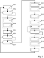
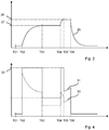
- the setting process is explained with reference to the control scheme in Fig. 2 and the time course in Fig. 3 explained.
- the setting device 1 is initially T01 in an idle state S01.
- the combustion chamber 4 is vented, in the combustion chamber 4 is essentially only air under ambient pressure.
- the compressor 17 is turned off and does not deliver air.
- the piston 6 is preferably in its the combustion chamber 4 minimizing the starting position.
- the exemplary barrel 8 is displaceable against a spring 25 in the housing 15 .
- the safety button 10 is actuated T02.
- the device controller 12 continuously checks S02 whether the safety button 10 is kept pressed. If the user releases the safety button 10 by the setting tool 1 is no longer pressed against the workpiece, the device control 12 interrupts the setting process and transfers the setting device 1 in its idle state S01.
- the compressor 17 is turned on S03.
- the speed 26 of the electric motor 19 is accelerated from initially zero to an intermediate value 27 .
- the intermediate value 27 is for example over 2 500 revolutions per second.
- the intermediate value 27 is preferably between 50% and 90% of the operating speed 28.
- the device controller 12 opens S04, the bypass valve 22, 23 is preferably at the beginning or during the acceleration to the intermediate value 27.
- the intake valve 21 of the combustion chamber 4 can be opened. If the bypass valve 23 is disposed in the combustion chamber 4 , the intake valve 21 is opened with the bypass valve 23 .
- the electric motor 19 keeps the rotational speed 26 at S05.
- the bypass valves 22, 23 remain fully open.
- the apparatus controller 12 waits S06 for the operation of the release button 11. If the release button 11 does not turn on within a predetermined period after the operation of the safety button 10 , the compressor 17 is turned off.
- the setting device 1 returns to the idle state S01.
- the compressor 17 accelerates S08 to its operating speed 28.
- the operating speed 28 is greater than 2,000 revolutions per second (180,000 rpm).
- the capacity of the compressor 17 reaches a value of 3 liters per second to 10 liters per second.
- the bypass valve 22 is closed in response to the actuation of the trigger button 11 S09.
- the closing S09 preferably takes place with the start T04 of the acceleration, can also during the acceleration or when T05 reaches the Operating speed 28 .
- the air flow now flows completely into the combustion chamber 4 .
- the combustion chamber 4 is not hermetically sealed, but allows a drain between 0.3 and 0.8 liters per second.
- the bypass valve 23 may remain open or only partially closed.
- the tiny radial fan can only build up a small static pressure difference.
- the operation permanently requires a high air flow, even if the target pressure has already been reached substantially.
- the pressure in the combustion chamber 4 increases due to the higher inflow than outflow to a target value between 1.3 and 3.5.
- the set value (compression) is indicated unitarily as the pressure ratio of the air in the combustion chamber 4 to the surroundings.
- the compression is specified by the device controller 12 .
- the device controller 12 determines the compression based on the ambient temperature and the ambient pressure.
- the device controller 12 determines S10 a duration (time T06 ) which the compressor 17 needs to reach the compression in the combustion chamber 4 . Until then, the compressor 17 is operated at the operating speed 28 S11.
- the combustible gas is injected into the combustion chamber 4 S12.
- the amount of combustible gas determines the implement controller 12 based on the ambient temperature and the ambient pressure.
- the amount of combustible gas and the amount of air are matched to achieve a desired set energy.
- the timing of the injection of the combustible gas is tuned to the use of the type of the bypass valve 22, 23 .
- the bypass valve in front of the combustion chamber 4 it proves to be advantageous to feed the combustible gas early, when substantially no pressure is built up in the combustion chamber 4 .
- the combustion chamber 4 is not designed pressure-tight. Airflow from the combustion chamber 4 is desirable because the high speed compressor 17 requires a permanent airflow. However, it should not be rinsed with the precious fuel gas. However, the combustible gas should be fed before reaching the compression. With closing of the inlet valve 21 , the pressure drops rapidly, for example at least 0.1 bar per 100 ms (milliseconds).
- the inlet valve 21 is closed S14 and the compressor 17 is switched off S15.
- a pressure sensor 29 may be provided in the combustion chamber 4 , which determines the achievement of the compression.
- the inlet valve 21 is closed T06, the combustible gas is ignited S16.
- the device controller 12 transmits a corresponding control signal to the detonator 13.
- the duration T04-T06 between the actuation of the trigger button 11 by the user and the ignition S15 is in the range of 50 ms to 150 ms. Duration T04-T06 is short in terms of safety requirements.
- the user should not be able to lift the setting tool 1 from the workpiece during this time.
- the piston 6 is accelerated as described and drives the nail 2 in the workpiece.
- the cooling of the combustion gases leads to a negative pressure in the combustion chamber 4, which retracts the piston 6 in its initial position.
- the inlet valve 21 is closed, as is the bypass valve 23.
- the compressor 17 and the battery 24 for the supply of the compressor 17 are additional components that contribute with their weight to the total weight of the setting tool 1 .
- the compression of the air makes it possible to make the combustion chamber 4 smaller because the same amount of oxygen is introduced in the smaller volume.
- the volume and weight of the combustion chamber 4 can be reduced.
- the effective weight reduction is probably only for a compression ratio between 1.3 and 3.5 feasible.
- the weight change of the combustion chamber 4 for a compression ratio of less than 1.3 does not yet weigh the additional components.
- a compression ratio of more than 3.5 allows a very light combustion chamber 4, but the advantage is offset by the weight of the compressor or problems with the fatigue strength of the compressor.
- the electric motor 19 is powered by a battery pack 24 .
- the high acceleration values of the electric motor 19 lead to high peak currents which, in particular, considerably burden conventional battery cells based on lithium-ion technology.
- the electric motor 19 is therefore provided with a motor control 30 , which achieves the high acceleration under moderate load of the battery pack 24 .
- the motor controller 30 regulates the line receptacle 31 of the electric motor 19 during the acceleration phase to a target power 32 from.
- the peculiarity of the regulated power consumption is that initially a high current 33 in the still dormant Electric motor 19 is fed and the current 33 is reduced with increasing speed of the electric motor 19 . With the speed 26 increases above the electric motor 19 falling voltage 34, which multiplied by the current 33 defines the power consumption 31 .
- the motor controller 30 preferably regulates the speed 26 of the electric motor 19 to a desired value 35.
- the desired value 35 may be the intermediate value 27 or the operating speed 28 , depending on the phase of setting.
- the exemplary motor controller 30 is shown in the block diagram of FIG Fig. 5 shown.
- the electric motor 19 is provided with a sensor 36 for determining the current actual rotational speed 26 .
- the sensor 36 may include, for example, a Hall sensor or determine the speed based on the periodically varied induced voltage in the motor coils. Other sensors commonly used with brushless motors can also be used.
- a comparator 37 compares the target speed 35 with the actual speed 26 and outputs a corresponding actuating signal 38 .
- the control signal 38 is a measure of the current which is to be fed into the electric motor 19 .
- a limiter 39 compares the control signal 38 with a permissible limit value and reduces the control signal 38 to the limit value when the limit value is exceeded.
- the limited actuating signal 40 is fed to a control loop 41 , which adjusts the current 33 in the electric motor 19 with a comparator 42 to the limited actuating signal 40 .
- the control loop 41 can, for example, change the voltage 34 applied to the electric motor 19 , a pulse width ratio etc. for controlling the current 33 .
- the speed control of the motor control 30 is supplemented by a feedback of the actual speed 26 in the limiter 39 to the power control during acceleration.
- the threshold is initially high at low actual speed 26 , thereby requiring a correspondingly high current from the control signal 38 33 is impressed in the electric motor 19 .
- the highest current 33 results when accelerating out of the rest.
- a proportionality factor [a] is preferably chosen such that when accelerating out of rest, the maximum allowable power of the battery 24 is retrieved.
- the proportionality factor can be fixed.
- the proportionality factor is determined as a function of the state of charge of the battery 24 .
- the proportionality factor is reduced with decreasing state of charge.
- the proportionality factor can be reduced with decreasing ambient temperature.
- the engine control 30 can equally be used for a motor 43 , which returns the piston 6 in the combustion chamber 4 against the setting direction 3 in the basic position.
- the motor 43 may be connected via a gear 44 to the piston 6 .
- the gear 44 preferably has a freewheel which decouples the motor 43 when the piston 6 moves in the setting direction 3 .
- the setting tool 1 has a temperature sensor 45 to determine the temperature of the environment.
- the device controller 12 determines, based on the temperature, the amount of combustible gas and the amount of air to set the nail 2 with the desired set energy.
- the support table contains for different temperatures and for different set energies the associated amounts of combustible gas and air or pressure in the combustion chamber 4. The compression of the air is reduced with decreasing temperature, also the amount of combustible gas in the combustion chamber 4 is reduced.
- the setting device 1 may have an adjusting element 46 , which allows the user to set the setting energy.
- a variation of the set energy is advantageous, for example, to optimize the setting in different ground or to allow the setting of a nail 2 with a soft silicone washer.
- the device controller 12 detects the set set energy and determined by means of tables, the necessary amount of combustible gas and to be reached in the combustion chamber 4 pressure. The latter sets the amount of oxygen in the combustion chamber 4 .
- the individual values can be determined in advance by test series and stored in a table.
- the engine controller 30 preferably adjusts the operating speed 28 in response to the pressure to be achieved, and at reduced pressure, a lower speed 26 is sufficient.
Landscapes
- Engineering & Computer Science (AREA)
- Mechanical Engineering (AREA)
- Chemical & Material Sciences (AREA)
- Combustion & Propulsion (AREA)
- Portable Nailing Machines And Staplers (AREA)
Claims (7)
- Machine-outil manuelle (1) destinée à poser un clou (2), comportant :un mécanisme de sécurité (10) pouvant être actionné par un utilisateur en pressant la machine-outil manuelle sur une pièce, et un bouton-poussoir (11) pouvant être actionné pour déclencher la pose du clou (2),une chambre de combustion (4) dans laquelle un mélange constitué d'un gaz combustible et d'air peut être enflammé,un piston (6) agencé dans la chambre de combustion (4) de manière à pouvoir être déplacé par des gaz de combustion dans une direction de pose (3),un poinçon (7) agencé sur le piston (6) pour pousser le clou (2) vers l'avant,un compresseur (17) pour comprimer l'air dans la chambre de combustion (4),un canal (20) reliant le compresseur (17) à la chambre de combustion (4),caractérisée parun clapet (22, 23) établissant une liaison entre le canal (20) ou la chambre de combustion (4) et le milieu environnant, le clapet (22, 23) étant ouvert entre l'actionnement du mécanisme de sécurité (10) et l'actionnement du bouton-poussoir (11).
- Machine-outil manuelle (1) selon la revendication 1, caractérisée en ce que le compresseur (17) est mis en marche dès l'actionnement du mécanisme de sécurité (10).
- Machine-outil manuelle (1) selon la revendication 1 ou 2, caractérisée en ce que le clapet (22, 23) est conçu pour dévier un écoulement d'air d'au moins 1 000 cm3 par seconde du compresseur (17) dans le milieu environnant.
- Machine-outil manuelle (1) selon l'une des revendications précédentes, caractérisée en ce que le clapet (22, 23) est fermé après l'actionnement du bouton-poussoir (11).
- Machine-outil manuelle (1) selon l'une des revendications précédentes, caractérisée en ce que le compresseur (17) comporte un moteur électrique (19) et une roue de ventilateur (18).
- Procédé de commande pour une machine-outil manuelle (1) destinée à poser des clous, la machine-outil manuelle comportant une chambre de combustion (4), un compresseur (17), un canal (20) reliant le compresseur (17) à la chambre de combustion (4), un clapet, un mécanisme de sécurité (10) et un bouton-poussoir (11) pouvant être actionné par l'utilisateur, comportant les étapes suivantes consistant à :mettre en marche le compresseur (17) en réponse à un actionnement du mécanisme de sécurité (10) en pressant la machine-outil manuelle sur une pièce, dans lequel de l'air fourni par le compresseur (17) s'écoule dans un canal (20) reliant le compresseur (17) à une chambre de combustion (4),ouvrir le clapet (22, 23) qui, à l'état ouvert, relie le canal (20) ou la chambre de combustion (4) à le milieu environnant, de sorte qu'au moins une partie de l'air fourni par le compresseur (17) est évacuée dans le milieu environnant,fermer le clapet (22, 23) en réponse à un actionnement du bouton-poussoir (11),introduire un gaz combustible dans la chambre de combustion (4),enflammer le mélange gazeux lorsqu'une pression de l'air dans la chambre de combustion (4) atteint une valeur prédéfinie, etarrêter le compresseur (17) lorsque la pression de l'air dans la chambre de combustion (4) atteint la valeur prédéfinie.
- Procédé de commande selon la revendication 6, caractérisé en ce que le compresseur (17) comporte un moteur électrique (19) et une roue de ventilateur (18), dans lequel le moteur électrique (19) est accéléré à une vitesse de rotation (26) égale à au moins 75 % d'une vitesse de rotation opérationnelle (28) en actionnant le mécanisme de sécurité, et est accéléré en réponse à l'actionnement du bouton-poussoir (11) jusqu'à la vitesse de rotation opérationnelle (28) d'au moins 2 000 tours par seconde.
Priority Applications (1)
| Application Number | Priority Date | Filing Date | Title |
|---|---|---|---|
| EP14738848.2A EP3022016B1 (fr) | 2013-07-16 | 2014-07-15 | Procédé de commande et machine-outil manuelle |
Applications Claiming Priority (3)
| Application Number | Priority Date | Filing Date | Title |
|---|---|---|---|
| EP13176596.8A EP2826599A1 (fr) | 2013-07-16 | 2013-07-16 | Procédé de commande et machine-outil manuelle |
| EP14738848.2A EP3022016B1 (fr) | 2013-07-16 | 2014-07-15 | Procédé de commande et machine-outil manuelle |
| PCT/EP2014/065073 WO2015007701A1 (fr) | 2013-07-16 | 2014-07-15 | Procédé de commande et outil manuel motorisé |
Publications (2)
| Publication Number | Publication Date |
|---|---|
| EP3022016A1 EP3022016A1 (fr) | 2016-05-25 |
| EP3022016B1 true EP3022016B1 (fr) | 2017-12-20 |
Family
ID=48790265
Family Applications (2)
| Application Number | Title | Priority Date | Filing Date |
|---|---|---|---|
| EP13176596.8A Withdrawn EP2826599A1 (fr) | 2013-07-16 | 2013-07-16 | Procédé de commande et machine-outil manuelle |
| EP14738848.2A Active EP3022016B1 (fr) | 2013-07-16 | 2014-07-15 | Procédé de commande et machine-outil manuelle |
Family Applications Before (1)
| Application Number | Title | Priority Date | Filing Date |
|---|---|---|---|
| EP13176596.8A Withdrawn EP2826599A1 (fr) | 2013-07-16 | 2013-07-16 | Procédé de commande et machine-outil manuelle |
Country Status (7)
| Country | Link |
|---|---|
| US (1) | US10058985B2 (fr) |
| EP (2) | EP2826599A1 (fr) |
| JP (1) | JP6216050B2 (fr) |
| CN (1) | CN105682861B (fr) |
| AU (1) | AU2014292183B2 (fr) |
| TW (1) | TWI610770B (fr) |
| WO (1) | WO2015007701A1 (fr) |
Families Citing this family (27)
| Publication number | Priority date | Publication date | Assignee | Title |
|---|---|---|---|---|
| DE102009041828A1 (de) * | 2009-09-18 | 2011-03-24 | Hilti Aktiengesellschaft | Vorrichtung zur Übertragung von Energie auf ein Befestigungselement |
| DE102009041824A1 (de) * | 2009-09-18 | 2011-03-24 | Hilti Aktiengesellschaft | Vorrichtung zur Übertragung von Energie auf ein Befestigungselement |
| EP2826600A1 (fr) | 2013-07-16 | 2015-01-21 | HILTI Aktiengesellschaft | Procédé de commande et machine-outil manuelle |
| WO2016127101A1 (fr) * | 2015-02-06 | 2016-08-11 | Milwaukee Electric Tool Corporation | Dispositif d'entraînement de fixation alimenté par ressort à gaz |
| EP3141347A1 (fr) * | 2015-09-14 | 2017-03-15 | HILTI Aktiengesellschaft | Appareil d'enfoncement entraine par combustible dote d'une articulation de soupape |
| EP3150336A1 (fr) * | 2015-09-29 | 2017-04-05 | HILTI Aktiengesellschaft | Appareil de pose fonctionnant avec des combustibles |
| TWI781941B (zh) * | 2016-07-29 | 2022-11-01 | 日商工機控股股份有限公司 | 釘打機 |
| TWI751176B (zh) * | 2016-08-31 | 2022-01-01 | 日商工機控股股份有限公司 | 打釘機、壓力調節器和打釘單元 |
| JP6677317B2 (ja) * | 2016-11-30 | 2020-04-08 | 工機ホールディングス株式会社 | 打込機 |
| JP7183543B2 (ja) * | 2018-02-09 | 2022-12-06 | マックス株式会社 | 打ち込み工具 |
| EP3575040A1 (fr) * | 2018-01-19 | 2019-12-04 | Max Co., Ltd. | Outil de commande |
| JP7091687B2 (ja) * | 2018-02-09 | 2022-06-28 | マックス株式会社 | 打ち込み工具 |
| KR102303861B1 (ko) * | 2018-01-19 | 2021-09-23 | 마크스 가부시기가이샤 | 타입 공구 |
| JP7031324B2 (ja) * | 2018-01-19 | 2022-03-08 | マックス株式会社 | ガス燃焼式打込み工具 |
| EP3524390B1 (fr) * | 2018-01-19 | 2022-03-30 | Max Co., Ltd. | Outil d'enfoncement |
| JP7004154B2 (ja) * | 2018-01-19 | 2022-01-21 | マックス株式会社 | ガス燃焼式打込み工具 |
| US11279014B2 (en) | 2018-01-19 | 2022-03-22 | Max Co., Ltd. | Gas combustion type driving tool |
| EP3578311A1 (fr) * | 2018-06-06 | 2019-12-11 | HILTI Aktiengesellschaft | Appareil de pose |
| US11130221B2 (en) | 2019-01-31 | 2021-09-28 | Milwaukee Electric Tool Corporation | Powered fastener driver |
| EP3822035A1 (fr) * | 2019-11-14 | 2021-05-19 | Hilti Aktiengesellschaft | Dispositif de poignée pour une machine-outil |
| JP7459648B2 (ja) * | 2020-05-14 | 2024-04-02 | マックス株式会社 | 打ち込み工具 |
| US11819989B2 (en) | 2020-07-07 | 2023-11-21 | Techtronic Cordless Gp | Powered fastener driver |
| EP4237201A4 (fr) | 2020-10-30 | 2024-12-11 | Milwaukee Electric Tool Corporation | Dispositif d'entraînement d'élément de fixation motorisé |
| JP7752824B2 (ja) * | 2021-05-10 | 2025-10-14 | マックス株式会社 | 打込工具 |
| CA3167425A1 (fr) | 2021-07-16 | 2023-01-16 | Techtronic Cordless Gp | Pose-attaches electrique |
| US12395046B2 (en) | 2022-07-22 | 2025-08-19 | Techtronic Cordless Gp | Firmware control providing a soft stop on compression drive nailer |
| CN115972153B (zh) * | 2023-03-22 | 2023-05-23 | 中铁十七局集团建筑工程有限公司 | 一种电动气压射钉枪 |
Family Cites Families (26)
| Publication number | Priority date | Publication date | Assignee | Title |
|---|---|---|---|---|
| US5390105A (en) * | 1992-10-01 | 1995-02-14 | Halliburton Company | Method and apparatus for controlling a device |
| US6123241A (en) * | 1995-05-23 | 2000-09-26 | Applied Tool Development Corporation | Internal combustion powered tool |
| US6604664B2 (en) * | 2001-01-16 | 2003-08-12 | Illinois Tool Works Inc. | Safe trigger with time delay for pneumatic fastener driving tools |
| DE10259816B4 (de) | 2002-12-19 | 2005-01-20 | Hilti Ag | Brennkraftbetriebenes Arbeitsgerät, insbesondere Setzgerät mit volumetrischer, gasförmiger Dosierung |
| DE10260704A1 (de) | 2002-12-23 | 2004-07-01 | Hilti Ag | Brennkraftbetriebenes Setzgerät |
| DE602004013860D1 (de) * | 2003-03-19 | 2008-07-03 | Hitachi Koki Kk | Verbrennungskraftbetriebenes Werkzeug mit Vorrichtung zur Vermeidung von Überhitzung der mechanischen Komponenten im Werkzeug |
| US20080217372A1 (en) * | 2003-12-30 | 2008-09-11 | Poly Systems Pty Ltd | Fastener Driving Tool |
| CN100439042C (zh) * | 2003-12-30 | 2008-12-03 | 多系统私人有限公司 | 紧固件推进工具 |
| JP4353076B2 (ja) * | 2004-11-16 | 2009-10-28 | 日立工機株式会社 | 燃焼式動力工具 |
| US7931181B2 (en) * | 2005-02-18 | 2011-04-26 | Hitachi Koki Co., Ltd. | Combustion-type power tool with trigger control arrangements |
| JP4923436B2 (ja) * | 2005-05-10 | 2012-04-25 | マックス株式会社 | ガス燃焼式打込み工具 |
| US7275505B2 (en) * | 2005-05-23 | 2007-10-02 | Illinois Tool Works Inc. | Thermal regulation control for combustion nailer |
| DE102005000149A1 (de) * | 2005-11-04 | 2007-05-10 | Hilti Ag | Brennkraftbetriebenes Setzgerät |
| TWI341773B (en) * | 2005-11-16 | 2011-05-11 | Illinois Tool Works | Fuel supply and combustion chamber systems for fastener-driving tools |
| CA2629761C (fr) * | 2005-11-17 | 2013-01-15 | Illinois Tool Works Inc. | Retard d'allumage variable pour cloueuse a combustion |
| JP5011900B2 (ja) * | 2006-09-07 | 2012-08-29 | マックス株式会社 | ガス燃焼式打込み工具の燃焼室の開閉機構 |
| JP2008255813A (ja) * | 2007-04-02 | 2008-10-23 | Max Co Ltd | ガス内燃式釘打機 |
| WO2009088896A1 (fr) * | 2008-01-04 | 2009-07-16 | Illinois Tool Works Inc. | Chambre de combustion et système de refroidissement pour des outils d'entraînement de fixation |
| DE102008000980B4 (de) * | 2008-04-03 | 2011-04-28 | Hilti Aktiengesellschaft | Verfahren zur Konfiguration einer Geräteelektronik eines handgeführten Arbeitsgeräts |
| DE102008000973A1 (de) * | 2008-04-03 | 2009-10-08 | Hilti Aktiengesellschaft | Handgeführtes Arbeitsgerät |
| US8550321B2 (en) * | 2008-05-21 | 2013-10-08 | Poly Systems Pty Ltd | Tool for driving fasteners |
| US8347832B2 (en) * | 2008-10-31 | 2013-01-08 | Illinois Tool Works Inc. | Fuel supply and combustion chamber systems for fastener-driving tools |
| JP5384282B2 (ja) | 2009-10-07 | 2014-01-08 | 株式会社マキタ | 燃焼式作業工具 |
| FR2955516B1 (fr) * | 2010-01-26 | 2012-04-20 | Prospection & Inventions | Procede de commande d'un outil a moteur a combustion interne et l'outil ainsi commande |
| JP5429010B2 (ja) * | 2010-04-02 | 2014-02-26 | マックス株式会社 | ガス燃焼式締結機 |
| EP2826600A1 (fr) | 2013-07-16 | 2015-01-21 | HILTI Aktiengesellschaft | Procédé de commande et machine-outil manuelle |
-
2013
- 2013-07-16 EP EP13176596.8A patent/EP2826599A1/fr not_active Withdrawn
-
2014
- 2014-06-16 TW TW103120680A patent/TWI610770B/zh active
- 2014-07-15 JP JP2016526569A patent/JP6216050B2/ja active Active
- 2014-07-15 EP EP14738848.2A patent/EP3022016B1/fr active Active
- 2014-07-15 WO PCT/EP2014/065073 patent/WO2015007701A1/fr not_active Ceased
- 2014-07-15 AU AU2014292183A patent/AU2014292183B2/en active Active
- 2014-07-15 US US14/904,276 patent/US10058985B2/en active Active
- 2014-07-15 CN CN201480040586.2A patent/CN105682861B/zh active Active
Also Published As
| Publication number | Publication date |
|---|---|
| AU2014292183B2 (en) | 2016-10-27 |
| AU2014292183A1 (en) | 2016-02-04 |
| WO2015007701A1 (fr) | 2015-01-22 |
| EP3022016A1 (fr) | 2016-05-25 |
| JP2016525454A (ja) | 2016-08-25 |
| JP6216050B2 (ja) | 2017-10-18 |
| CN105682861B (zh) | 2018-08-07 |
| CN105682861A (zh) | 2016-06-15 |
| TWI610770B (zh) | 2018-01-11 |
| TW201515784A (zh) | 2015-05-01 |
| EP2826599A1 (fr) | 2015-01-21 |
| US10058985B2 (en) | 2018-08-28 |
| US20160144496A1 (en) | 2016-05-26 |
Similar Documents
| Publication | Publication Date | Title |
|---|---|---|
| EP3022016B1 (fr) | Procédé de commande et machine-outil manuelle | |
| EP3022017B1 (fr) | Procédé de commande et machine-outil manuelle | |
| EP3022018A1 (fr) | Procédé de commande et machine-outil portative | |
| EP2650087A2 (fr) | Appareil d'enfoncement | |
| EP2465641B1 (fr) | Outil électrique de fixation de boulons | |
| EP2465643B1 (fr) | Appareil de fixation de boulons et procédé de fonctionnement d'un appareil de fixation de boulons | |
| EP3349945B1 (fr) | Appareil d'enfoncement entraîné par combustible doté d'une articulation de soupape | |
| EP3349944B1 (fr) | Appareil d'enfoncement entraîné par combustible doté d'une articulation de soupape | |
| DE102013021832A1 (de) | Verfahren zum Betrieb eines handgeführten Arbeitsgeräts mit einem Verbrennungsmotor | |
| EP2851158A1 (fr) | Dispositif d'entraînement avec accumulateur pneumatique chauffé | |
| DE102006000127B4 (de) | Brennkraftbetriebenes Setzgerät | |
| EP2457697A2 (fr) | Appareil d'enfoncement | |
| WO2017102469A1 (fr) | Appareil d'enfoncement fonctionnant au gaz combustible | |
| DE202005011723U1 (de) | Gasdrucknagler | |
| WO2006029784A1 (fr) | Procede et dispositif pour agir sur des personnes cibles de maniere non letale | |
| EP2457696A2 (fr) | Appareil d'enfoncement |
Legal Events
| Date | Code | Title | Description |
|---|---|---|---|
| PUAI | Public reference made under article 153(3) epc to a published international application that has entered the european phase |
Free format text: ORIGINAL CODE: 0009012 |
|
| 17P | Request for examination filed |
Effective date: 20160216 |
|
| AK | Designated contracting states |
Kind code of ref document: A1 Designated state(s): AL AT BE BG CH CY CZ DE DK EE ES FI FR GB GR HR HU IE IS IT LI LT LU LV MC MK MT NL NO PL PT RO RS SE SI SK SM TR |
|
| AX | Request for extension of the european patent |
Extension state: BA ME |
|
| DAX | Request for extension of the european patent (deleted) | ||
| GRAP | Despatch of communication of intention to grant a patent |
Free format text: ORIGINAL CODE: EPIDOSNIGR1 |
|
| INTG | Intention to grant announced |
Effective date: 20170908 |
|
| RIN1 | Information on inventor provided before grant (corrected) |
Inventor name: CLAUSI, DONATO Inventor name: HANNOSCHOECK, NIKOLAUS Inventor name: RAGGL, KLAUS Inventor name: BOEHM, CHRISTOPH |
|
| GRAS | Grant fee paid |
Free format text: ORIGINAL CODE: EPIDOSNIGR3 |
|
| GRAA | (expected) grant |
Free format text: ORIGINAL CODE: 0009210 |
|
| AK | Designated contracting states |
Kind code of ref document: B1 Designated state(s): AL AT BE BG CH CY CZ DE DK EE ES FI FR GB GR HR HU IE IS IT LI LT LU LV MC MK MT NL NO PL PT RO RS SE SI SK SM TR |
|
| REG | Reference to a national code |
Ref country code: GB Ref legal event code: FG4D Free format text: NOT ENGLISH |
|
| REG | Reference to a national code |
Ref country code: CH Ref legal event code: EP |
|
| REG | Reference to a national code |
Ref country code: IE Ref legal event code: FG4D Free format text: LANGUAGE OF EP DOCUMENT: GERMAN |
|
| REG | Reference to a national code |
Ref country code: AT Ref legal event code: REF Ref document number: 955932 Country of ref document: AT Kind code of ref document: T Effective date: 20180115 |
|
| REG | Reference to a national code |
Ref country code: DE Ref legal event code: R096 Ref document number: 502014006670 Country of ref document: DE |
|
| REG | Reference to a national code |
Ref country code: NL Ref legal event code: MP Effective date: 20171220 |
|
| PG25 | Lapsed in a contracting state [announced via postgrant information from national office to epo] |
Ref country code: NO Free format text: LAPSE BECAUSE OF FAILURE TO SUBMIT A TRANSLATION OF THE DESCRIPTION OR TO PAY THE FEE WITHIN THE PRESCRIBED TIME-LIMIT Effective date: 20180320 Ref country code: LT Free format text: LAPSE BECAUSE OF FAILURE TO SUBMIT A TRANSLATION OF THE DESCRIPTION OR TO PAY THE FEE WITHIN THE PRESCRIBED TIME-LIMIT Effective date: 20171220 Ref country code: FI Free format text: LAPSE BECAUSE OF FAILURE TO SUBMIT A TRANSLATION OF THE DESCRIPTION OR TO PAY THE FEE WITHIN THE PRESCRIBED TIME-LIMIT Effective date: 20171220 Ref country code: SE Free format text: LAPSE BECAUSE OF FAILURE TO SUBMIT A TRANSLATION OF THE DESCRIPTION OR TO PAY THE FEE WITHIN THE PRESCRIBED TIME-LIMIT Effective date: 20171220 |
|
| REG | Reference to a national code |
Ref country code: LT Ref legal event code: MG4D |
|
| PG25 | Lapsed in a contracting state [announced via postgrant information from national office to epo] |
Ref country code: LV Free format text: LAPSE BECAUSE OF FAILURE TO SUBMIT A TRANSLATION OF THE DESCRIPTION OR TO PAY THE FEE WITHIN THE PRESCRIBED TIME-LIMIT Effective date: 20171220 Ref country code: RS Free format text: LAPSE BECAUSE OF FAILURE TO SUBMIT A TRANSLATION OF THE DESCRIPTION OR TO PAY THE FEE WITHIN THE PRESCRIBED TIME-LIMIT Effective date: 20171220 Ref country code: BG Free format text: LAPSE BECAUSE OF FAILURE TO SUBMIT A TRANSLATION OF THE DESCRIPTION OR TO PAY THE FEE WITHIN THE PRESCRIBED TIME-LIMIT Effective date: 20180320 Ref country code: HR Free format text: LAPSE BECAUSE OF FAILURE TO SUBMIT A TRANSLATION OF THE DESCRIPTION OR TO PAY THE FEE WITHIN THE PRESCRIBED TIME-LIMIT Effective date: 20171220 Ref country code: GR Free format text: LAPSE BECAUSE OF FAILURE TO SUBMIT A TRANSLATION OF THE DESCRIPTION OR TO PAY THE FEE WITHIN THE PRESCRIBED TIME-LIMIT Effective date: 20180321 |
|
| PG25 | Lapsed in a contracting state [announced via postgrant information from national office to epo] |
Ref country code: NL Free format text: LAPSE BECAUSE OF FAILURE TO SUBMIT A TRANSLATION OF THE DESCRIPTION OR TO PAY THE FEE WITHIN THE PRESCRIBED TIME-LIMIT Effective date: 20171220 |
|
| REG | Reference to a national code |
Ref country code: FR Ref legal event code: PLFP Year of fee payment: 5 |
|
| PG25 | Lapsed in a contracting state [announced via postgrant information from national office to epo] |
Ref country code: EE Free format text: LAPSE BECAUSE OF FAILURE TO SUBMIT A TRANSLATION OF THE DESCRIPTION OR TO PAY THE FEE WITHIN THE PRESCRIBED TIME-LIMIT Effective date: 20171220 Ref country code: SK Free format text: LAPSE BECAUSE OF FAILURE TO SUBMIT A TRANSLATION OF THE DESCRIPTION OR TO PAY THE FEE WITHIN THE PRESCRIBED TIME-LIMIT Effective date: 20171220 Ref country code: ES Free format text: LAPSE BECAUSE OF FAILURE TO SUBMIT A TRANSLATION OF THE DESCRIPTION OR TO PAY THE FEE WITHIN THE PRESCRIBED TIME-LIMIT Effective date: 20171220 Ref country code: CZ Free format text: LAPSE BECAUSE OF FAILURE TO SUBMIT A TRANSLATION OF THE DESCRIPTION OR TO PAY THE FEE WITHIN THE PRESCRIBED TIME-LIMIT Effective date: 20171220 Ref country code: CY Free format text: LAPSE BECAUSE OF FAILURE TO SUBMIT A TRANSLATION OF THE DESCRIPTION OR TO PAY THE FEE WITHIN THE PRESCRIBED TIME-LIMIT Effective date: 20171220 |
|
| PG25 | Lapsed in a contracting state [announced via postgrant information from national office to epo] |
Ref country code: SM Free format text: LAPSE BECAUSE OF FAILURE TO SUBMIT A TRANSLATION OF THE DESCRIPTION OR TO PAY THE FEE WITHIN THE PRESCRIBED TIME-LIMIT Effective date: 20171220 Ref country code: PL Free format text: LAPSE BECAUSE OF FAILURE TO SUBMIT A TRANSLATION OF THE DESCRIPTION OR TO PAY THE FEE WITHIN THE PRESCRIBED TIME-LIMIT Effective date: 20171220 Ref country code: IS Free format text: LAPSE BECAUSE OF FAILURE TO SUBMIT A TRANSLATION OF THE DESCRIPTION OR TO PAY THE FEE WITHIN THE PRESCRIBED TIME-LIMIT Effective date: 20180420 Ref country code: RO Free format text: LAPSE BECAUSE OF FAILURE TO SUBMIT A TRANSLATION OF THE DESCRIPTION OR TO PAY THE FEE WITHIN THE PRESCRIBED TIME-LIMIT Effective date: 20171220 Ref country code: IT Free format text: LAPSE BECAUSE OF FAILURE TO SUBMIT A TRANSLATION OF THE DESCRIPTION OR TO PAY THE FEE WITHIN THE PRESCRIBED TIME-LIMIT Effective date: 20171220 |
|
| REG | Reference to a national code |
Ref country code: DE Ref legal event code: R097 Ref document number: 502014006670 Country of ref document: DE |
|
| PG25 | Lapsed in a contracting state [announced via postgrant information from national office to epo] |
Ref country code: MT Free format text: LAPSE BECAUSE OF FAILURE TO SUBMIT A TRANSLATION OF THE DESCRIPTION OR TO PAY THE FEE WITHIN THE PRESCRIBED TIME-LIMIT Effective date: 20171220 |
|
| PLBE | No opposition filed within time limit |
Free format text: ORIGINAL CODE: 0009261 |
|
| STAA | Information on the status of an ep patent application or granted ep patent |
Free format text: STATUS: NO OPPOSITION FILED WITHIN TIME LIMIT |
|
| 26N | No opposition filed |
Effective date: 20180921 |
|
| PG25 | Lapsed in a contracting state [announced via postgrant information from national office to epo] |
Ref country code: DK Free format text: LAPSE BECAUSE OF FAILURE TO SUBMIT A TRANSLATION OF THE DESCRIPTION OR TO PAY THE FEE WITHIN THE PRESCRIBED TIME-LIMIT Effective date: 20171220 |
|
| PG25 | Lapsed in a contracting state [announced via postgrant information from national office to epo] |
Ref country code: SI Free format text: LAPSE BECAUSE OF FAILURE TO SUBMIT A TRANSLATION OF THE DESCRIPTION OR TO PAY THE FEE WITHIN THE PRESCRIBED TIME-LIMIT Effective date: 20171220 |
|
| REG | Reference to a national code |
Ref country code: CH Ref legal event code: PL |
|
| PG25 | Lapsed in a contracting state [announced via postgrant information from national office to epo] |
Ref country code: MC Free format text: LAPSE BECAUSE OF FAILURE TO SUBMIT A TRANSLATION OF THE DESCRIPTION OR TO PAY THE FEE WITHIN THE PRESCRIBED TIME-LIMIT Effective date: 20171220 Ref country code: LU Free format text: LAPSE BECAUSE OF NON-PAYMENT OF DUE FEES Effective date: 20180715 |
|
| REG | Reference to a national code |
Ref country code: BE Ref legal event code: MM Effective date: 20180731 |
|
| REG | Reference to a national code |
Ref country code: IE Ref legal event code: MM4A |
|
| PG25 | Lapsed in a contracting state [announced via postgrant information from national office to epo] |
Ref country code: LI Free format text: LAPSE BECAUSE OF NON-PAYMENT OF DUE FEES Effective date: 20180731 Ref country code: IE Free format text: LAPSE BECAUSE OF NON-PAYMENT OF DUE FEES Effective date: 20180715 Ref country code: CH Free format text: LAPSE BECAUSE OF NON-PAYMENT OF DUE FEES Effective date: 20180731 |
|
| PG25 | Lapsed in a contracting state [announced via postgrant information from national office to epo] |
Ref country code: BE Free format text: LAPSE BECAUSE OF NON-PAYMENT OF DUE FEES Effective date: 20180731 |
|
| PG25 | Lapsed in a contracting state [announced via postgrant information from national office to epo] |
Ref country code: TR Free format text: LAPSE BECAUSE OF FAILURE TO SUBMIT A TRANSLATION OF THE DESCRIPTION OR TO PAY THE FEE WITHIN THE PRESCRIBED TIME-LIMIT Effective date: 20171220 |
|
| PG25 | Lapsed in a contracting state [announced via postgrant information from national office to epo] |
Ref country code: PT Free format text: LAPSE BECAUSE OF FAILURE TO SUBMIT A TRANSLATION OF THE DESCRIPTION OR TO PAY THE FEE WITHIN THE PRESCRIBED TIME-LIMIT Effective date: 20171220 |
|
| PG25 | Lapsed in a contracting state [announced via postgrant information from national office to epo] |
Ref country code: MK Free format text: LAPSE BECAUSE OF NON-PAYMENT OF DUE FEES Effective date: 20171220 Ref country code: HU Free format text: LAPSE BECAUSE OF FAILURE TO SUBMIT A TRANSLATION OF THE DESCRIPTION OR TO PAY THE FEE WITHIN THE PRESCRIBED TIME-LIMIT; INVALID AB INITIO Effective date: 20140715 |
|
| PG25 | Lapsed in a contracting state [announced via postgrant information from national office to epo] |
Ref country code: AL Free format text: LAPSE BECAUSE OF FAILURE TO SUBMIT A TRANSLATION OF THE DESCRIPTION OR TO PAY THE FEE WITHIN THE PRESCRIBED TIME-LIMIT Effective date: 20171220 |
|
| REG | Reference to a national code |
Ref country code: AT Ref legal event code: MM01 Ref document number: 955932 Country of ref document: AT Kind code of ref document: T Effective date: 20190715 |
|
| PG25 | Lapsed in a contracting state [announced via postgrant information from national office to epo] |
Ref country code: AT Free format text: LAPSE BECAUSE OF NON-PAYMENT OF DUE FEES Effective date: 20190715 |
|
| PGFP | Annual fee paid to national office [announced via postgrant information from national office to epo] |
Ref country code: DE Payment date: 20250722 Year of fee payment: 12 |
|
| PGFP | Annual fee paid to national office [announced via postgrant information from national office to epo] |
Ref country code: GB Payment date: 20250722 Year of fee payment: 12 |
|
| PGFP | Annual fee paid to national office [announced via postgrant information from national office to epo] |
Ref country code: FR Payment date: 20250725 Year of fee payment: 12 |