EP3022085B1 - Kopfstützen-trägerstruktur - Google Patents
Kopfstützen-trägerstruktur Download PDFInfo
- Publication number
- EP3022085B1 EP3022085B1 EP14766195.3A EP14766195A EP3022085B1 EP 3022085 B1 EP3022085 B1 EP 3022085B1 EP 14766195 A EP14766195 A EP 14766195A EP 3022085 B1 EP3022085 B1 EP 3022085B1
- Authority
- EP
- European Patent Office
- Prior art keywords
- headrest
- headrest support
- protrusion
- bracket
- inner peripheral
- Prior art date
- Legal status (The legal status is an assumption and is not a legal conclusion. Google has not performed a legal analysis and makes no representation as to the accuracy of the status listed.)
- Not-in-force
Links
Images


Classifications
-
- B—PERFORMING OPERATIONS; TRANSPORTING
- B60—VEHICLES IN GENERAL
- B60N—SEATS SPECIALLY ADAPTED FOR VEHICLES; VEHICLE PASSENGER ACCOMMODATION NOT OTHERWISE PROVIDED FOR
- B60N2/00—Seats specially adapted for vehicles; Arrangement or mounting of seats in vehicles
- B60N2/80—Head-rests
- B60N2/806—Head-rests movable or adjustable
- B60N2/809—Head-rests movable or adjustable vertically slidable
-
- A—HUMAN NECESSITIES
- A47—FURNITURE; DOMESTIC ARTICLES OR APPLIANCES; COFFEE MILLS; SPICE MILLS; SUCTION CLEANERS IN GENERAL
- A47C—CHAIRS; SOFAS; BEDS
- A47C7/00—Parts, details, or accessories of chairs or stools
- A47C7/36—Supports for the head or the back
- A47C7/38—Supports for the head or the back for the head, e.g. detachable
- A47C7/383—Detachable or loose head- or neck-supports, e.g. horse-shoe shaped
-
- A—HUMAN NECESSITIES
- A47—FURNITURE; DOMESTIC ARTICLES OR APPLIANCES; COFFEE MILLS; SPICE MILLS; SUCTION CLEANERS IN GENERAL
- A47C—CHAIRS; SOFAS; BEDS
- A47C7/00—Parts, details, or accessories of chairs or stools
- A47C7/36—Supports for the head or the back
-
- B—PERFORMING OPERATIONS; TRANSPORTING
- B60—VEHICLES IN GENERAL
- B60N—SEATS SPECIALLY ADAPTED FOR VEHICLES; VEHICLE PASSENGER ACCOMMODATION NOT OTHERWISE PROVIDED FOR
- B60N2/00—Seats specially adapted for vehicles; Arrangement or mounting of seats in vehicles
- B60N2/68—Seat frames
-
- B—PERFORMING OPERATIONS; TRANSPORTING
- B60—VEHICLES IN GENERAL
- B60N—SEATS SPECIALLY ADAPTED FOR VEHICLES; VEHICLE PASSENGER ACCOMMODATION NOT OTHERWISE PROVIDED FOR
- B60N2/00—Seats specially adapted for vehicles; Arrangement or mounting of seats in vehicles
- B60N2/68—Seat frames
- B60N2/682—Joining means
-
- B—PERFORMING OPERATIONS; TRANSPORTING
- B60—VEHICLES IN GENERAL
- B60N—SEATS SPECIALLY ADAPTED FOR VEHICLES; VEHICLE PASSENGER ACCOMMODATION NOT OTHERWISE PROVIDED FOR
- B60N2/00—Seats specially adapted for vehicles; Arrangement or mounting of seats in vehicles
- B60N2/68—Seat frames
- B60N2/686—Panel like structures
-
- B—PERFORMING OPERATIONS; TRANSPORTING
- B60—VEHICLES IN GENERAL
- B60N—SEATS SPECIALLY ADAPTED FOR VEHICLES; VEHICLE PASSENGER ACCOMMODATION NOT OTHERWISE PROVIDED FOR
- B60N2/00—Seats specially adapted for vehicles; Arrangement or mounting of seats in vehicles
- B60N2/70—Upholstery springs ; Upholstery
- B60N2/7094—Upholstery springs
-
- B—PERFORMING OPERATIONS; TRANSPORTING
- B60—VEHICLES IN GENERAL
- B60N—SEATS SPECIALLY ADAPTED FOR VEHICLES; VEHICLE PASSENGER ACCOMMODATION NOT OTHERWISE PROVIDED FOR
- B60N2/00—Seats specially adapted for vehicles; Arrangement or mounting of seats in vehicles
- B60N2/70—Upholstery springs ; Upholstery
- B60N2/72—Attachment or adjustment thereof
-
- B—PERFORMING OPERATIONS; TRANSPORTING
- B60—VEHICLES IN GENERAL
- B60N—SEATS SPECIALLY ADAPTED FOR VEHICLES; VEHICLE PASSENGER ACCOMMODATION NOT OTHERWISE PROVIDED FOR
- B60N2/00—Seats specially adapted for vehicles; Arrangement or mounting of seats in vehicles
- B60N2/80—Head-rests
-
- B—PERFORMING OPERATIONS; TRANSPORTING
- B60—VEHICLES IN GENERAL
- B60N—SEATS SPECIALLY ADAPTED FOR VEHICLES; VEHICLE PASSENGER ACCOMMODATION NOT OTHERWISE PROVIDED FOR
- B60N2/00—Seats specially adapted for vehicles; Arrangement or mounting of seats in vehicles
- B60N2/80—Head-rests
- B60N2/806—Head-rests movable or adjustable
- B60N2/809—Head-rests movable or adjustable vertically slidable
- B60N2/812—Head-rests movable or adjustable vertically slidable characterised by their locking devices
- B60N2/821—Head-rests movable or adjustable vertically slidable characterised by their locking devices with continuous positioning
- B60N2/826—Head-rests movable or adjustable vertically slidable characterised by their locking devices with continuous positioning using rubber-type material
-
- B—PERFORMING OPERATIONS; TRANSPORTING
- B60—VEHICLES IN GENERAL
- B60N—SEATS SPECIALLY ADAPTED FOR VEHICLES; VEHICLE PASSENGER ACCOMMODATION NOT OTHERWISE PROVIDED FOR
- B60N2/00—Seats specially adapted for vehicles; Arrangement or mounting of seats in vehicles
- B60N2/80—Head-rests
- B60N2/806—Head-rests movable or adjustable
- B60N2/809—Head-rests movable or adjustable vertically slidable
- B60N2/832—Head-rests movable or adjustable vertically slidable movable to an inoperative or stowed position
-
- B—PERFORMING OPERATIONS; TRANSPORTING
- B60—VEHICLES IN GENERAL
- B60N—SEATS SPECIALLY ADAPTED FOR VEHICLES; VEHICLE PASSENGER ACCOMMODATION NOT OTHERWISE PROVIDED FOR
- B60N2/00—Seats specially adapted for vehicles; Arrangement or mounting of seats in vehicles
- B60N2/80—Head-rests
- B60N2/894—Head-rests with rods solidly attached to the back-rest
-
- B—PERFORMING OPERATIONS; TRANSPORTING
- B60—VEHICLES IN GENERAL
- B60N—SEATS SPECIALLY ADAPTED FOR VEHICLES; VEHICLE PASSENGER ACCOMMODATION NOT OTHERWISE PROVIDED FOR
- B60N2/00—Seats specially adapted for vehicles; Arrangement or mounting of seats in vehicles
- B60N2/80—Head-rests
- B60N2/897—Head-rests with sleeves located in the back-rest for guiding the rods of the head-rest
-
- B—PERFORMING OPERATIONS; TRANSPORTING
- B60—VEHICLES IN GENERAL
- B60N—SEATS SPECIALLY ADAPTED FOR VEHICLES; VEHICLE PASSENGER ACCOMMODATION NOT OTHERWISE PROVIDED FOR
- B60N2205/00—General mechanical or structural details
- B60N2205/20—Measures for elimination or compensation of play or backlash
Definitions
- the invention relates to a headrest support structure that pivotally supports a headrest.
- One known headrest support structure makes a headrest serve as a dynamic damper by pivotally elastically-supporting the headrest on a seat back.
- FIG. 7 is a view of the structure of a headrest support structure described in JP 61-149552 U .
- This headrest support structure has a bracket 51 that is fixed to a seat back frame 50 that is a frame member of a seat back.
- the bracket 51 is fonned by a metal plate member that is bent in a general sideways U-shape.
- Through-holes 52 and 53 are formed in an upper portion and a lower portion, respectively, of this bracket 51.
- Headrest supports 54 that are made of resin and support headrest stays are inserted into these through-holes 52 and 53.
- the through-hole 52 formed in the upper portion of the bracket 51 is a slotted hole that is long in a seat front-rear direction.
- a wire-like spring 55 that is made of metal extends across a portion that is toward the seat front.
- the headrest supports 54 is allowed to pivot ever so slightly with respect to the bracket 51 while being elastically supported. Therefore, with a seat in which the headrest is supported by this kind of support structure, the headrest serves as a dynamic damper that reduces seat vibrations by resonance vibration of the headrest.
- the damper property of the headrest needs to be appropriately set such that the resonance frequency of the headrest matches the frequency of reduced seat vibration.
- the headrest support structure according to the related art unless the fit of the headrest supports 54 in the through-holes 52 and 53 of the bracket 51 is sufficiently tight, the position of the pivot center of the headrest supports 54 with respect to the bracket 51, and thus the position of the pivot center of the headrest, will change, and as a result, the damper property of the headrest will end up changing.
- the fit of these headrest supports 54 is tight, assembly of the headrest supports 54 into the brackets 51 may be difficult.
- the invention thus provides a headrest support structure capable of easily and adequately ensuring pivot operation accuracy of a headrest.
- a first aspect of the invention relates to a headrest support structure that includes a headrest support having a hollow cylindrical shape, into which a headrest stay is inserted; and a bracket having a hollow cylindrical shape that is fixed to a seat back frame, and into which the headrest support is inserted.
- the headrest support is pivotally supported with respect to the bracket, around a contact portion between a tip end of a protrusion provided on an outer peripheral surface of the headrest support and an inner peripheral surface of the bracket.
- the protrusion is formed such that a protrusion amount thereof toward an outer peripheral side of the headrest support increases in response to insertion of the headrest stay.
- a protrusion is provided on the outer peripheral surface of the headrest support, and the contact portion between the tip end of this protrusion and the inner peripheral surface of the bracket is a pivot center of the headrest support with respect to the bracket. Therefore, the position of the pivot center of the headrest is stable. Also, when the headrest stay is not inserted, the amount that the protrusion protrudes toward the outer peripheral side of the headrest support is less than it is originally, so interference from the protrusion with respect to the inner peripheral surface of the bracket is inhibited, which enables the headrest support to be inserted more smoothly. Therefore, with this kind of headrest support structure, the pivot operation accuracy of the headrest is able to be easily and adequately ensured.
- a second aspect of the invention relates to a headrest support structure that includes a headrest support having a hollow cylindrical shape, into which a headrest stay is inserted; and a bracket having a hollow cylindrical shape that is fixed to a seat back frame, and into which the headrest support is inserted.
- the headrest support is pivotally supported with respect to the bracket, around a contact portion between a tip end of a protrusion provided on an outer peripheral surface of the headrest support and an inner peripheral surface of the bracket.
- An inner peripheral surface of the headrest support when the headrest stay is not inserted locally bulges out toward an inner peripheral side of the headrest support, at a location where the protrusion is formed.
- a protrusion is provided on the outer peripheral surface of the headrest support, and the contact portion between the tip end of this protrusion and the inner peripheral surface of the bracket is a pivot center of the headrest support with respect to the bracket. Therefore, the position of the pivot center of the headrest is stable.
- the portion of the inner peripheral surface of the headrest support that locally bulges out is pushed on by the headrest stay, such that the protrusion is pushed out to the outer peripheral side. That is, when the headrest stay is not inserted, the amount that the protrusion protrudes toward the outer peripheral side of the headrest support is less than it is originally.
- the headrest support of these headrest support structures If two slits provided in parallel are formed in the headrest support of these headrest support structures so as to sandwich the headrest, the force required to accomplish the deformation of the headrest support that acts to increase the protrusion amount of the protrusion is able to be reduced. Therefore, the headrest stay is also able to be inserted into the headrest support smoothly.
- a position of the tip end of the protrusion when the headrest stay is not inserted may be a position in which the tip end of the protrusion does not contact the inner peripheral surface of the bracket when the headrest support is inserted into the bracket and the headrest stay is not inserted.
- This headrest support structure may also include an elastic member provided on the headrest support, and this elastic member may elastically support a headrest via the headrest stay.
- a direction corresponding to forward of an occupant seated in a seat will be referred to as "seat front F”
- a direction corresponding to rearward of the occupant will be referred to as "seat rear B”
- a direction corresponding to the left of the occupant will be referred to as “seat left L”
- a direction corresponding to the right of the occupant will be referred to as "seat right R”.
- a direction to a side where the headrest is positioned when viewed from the seat back will be referred to as "seat upper U” or “above U in the vertical direction of the seat”, and a direction opposite this direction will be referred to as “seat lower D” or “below D in the vertical direction of the seat”.
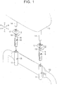
- the headrest support structure of this example embodiment includes two brackets 11 that are fixed to a seat back frame 10 that forms a frame of a seat back, and two headrest supports 12 that are inserted into these brackets 11. Also, a headrest 13 is supported on the seat back frame 10 by two headrest stays 14 that extend below the headrest 13 being inserted into these headrest supports 12.
- Each of the brackets 11 is formed in a hollow cylindrical shape that has a generally square cross-section. Also, each bracket 11 is fixed to a seat upper U portion of the seat back frame 10 by welding or the like. A retaining hole 15 is open in each side surface on a seat left L and a seat right R of each bracket 11.
- Each headrest support 12 has a cylindrical portion 16 that is formed in a hollow cylindrical shape that has a generally square cross-section, and that is inserted into the bracket 11, and a head portion 17 formed above this cylindrical portion 16.
- the cylindrical portion 16 and the head portion 17 are made of resin.
- the cylindrical portion 16 is integrally formed with the head portion 17.
- a pawl 18 that protrudes toward an outer peripheral side is provided on both the side surface of the cylindrical portion 16 on the seat left L and the seat right R. Also, the headrest supports 12 are fixed to the brackets 11 by the pawls 18 engaging with the retaining holes 15 of the brackets 11.
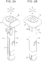
- FIG. 2A is a view of the headrest support 12 viewed from the seat front F side.
- a protrusion 19 that protrudes in a convex shape toward the outer peripheral side of the cylindrical portion 16 is provided on an outer peripheral surface of a seat upper U portion on the seat front F side of the cylindrical portion 16.
- a bulging portion 25 that bulges out toward the inner peripheral side of the cylindrical portion 16 is provided on a back surface of the protrusion 19, i.e., an inner peripheral surface of the headrest support 12 at the location where the protrusion 19 is formed.
- two slits 20 provided in parallel are open in the side surface of the cylindrical portion 16 so as to sandwich the protrusion 19.
- FIG. 2B is a view of the headrest support 12 viewed from the seat rear B side.
- a plate spring 22 is provided on a seat lower D portion on the seat rear B side of the cylindrical portion 16.
- the plate spring 22 is formed as a separate member made of metal, and is fixed in place by fitting into the outer peripheral surface of the cylindrical portion 16.
- a protruding bead 21 is formed on the seat front F side at a location corresponding to where the protrusion 19 is formed, on the outer peripheral surface of a seat lower D portion of the cylindrical portion 16. Also, as shown in FIG. 2B , a protruding bead 24 is also formed on the seat rear B side at a location corresponding to where the plate spring 22 is arranged, on the outer peripheral surface of a seat upper U portion of the cylindrical portion 16.
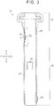
- FIG. 3 is a view of the sectional structure of the headrest support 12 taken along line A - A in FIGS. 2A and 2B when the headrest stay 14 is not inserted.
- a side wall of the headrest support 12 at a portion around the protrusion 19 curves toward the inner peripheral side when the headrest stays 14 is not inserted.
- a tip end T of the protrusion 19 is positioned farther toward the inner peripheral side than the outer peripheral surface of the cylindrical portion 16 at the portion where the bead 21 is formed, in the radial direction of the cylindrical portion 16.
- FIGS. 4A to 4C are views of an assembly procedure of the headrest 13 of the headrest support structure of this example embodiment.
- the headrest support 12 is first inserted into the bracket 11.
- the tip end T of the protrusion 19 at this time is positioned farther to the inner peripheral side than the outer peripheral surface of the cylindrical portion 16 at the portion where the bead 21 is formed.
- the plate spring 22 at this time is flexed toward the inner peripheral side of the cylindrical portion 16 in response to it abutting against the inner peripheral surface of the bracket 11.
- the headrest stay 14 is inserted into the headrest support 12, as shown in FIG. 4B .
- the bulging portion 25 on the back surface of the protrusion 19 is pushed on by the headrest stay 14, such that the protrusion 19 protrudes out toward the outer peripheral side of the cylindrical portion 16.
- the headrest support 12 is supported by the bracket 11 in a manner that enables it to pivot in the seat front-rear direction around a contact portion between the tip end of the protrusion 19 that is provided on the outer peripheral surface of the headrest support 12, and the inner peripheral surface of the bracket 11.
- the headrest support 12 pivots in a direction in which the end portion thereof on the seat lower D side is displaced toward the seat rear B, around the tip end T of the protrusion 19 that abuts against the inner peripheral surface of the bracket 11.
- the plate spring 22 at this time flexes further toward the inner peripheral side in response to this pivoting.
- the bracket 11 at this time receives the load P1 applied to the headrest stay 14, via the plate spring 22. Therefore, the headrest 13 at this time is elastically supported via the plate spring 22.
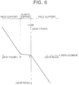
- FIG. 6 is a view showing the relationship between the load applied to the headrest 13 and the amount of displacement of the headrest 13.
- the headrest 13 is able to be displaced with respect to the seat front F by a relatively small load, until the end portion of the headrest support 12 comes to a position ⁇ where it abuts against the inner peripheral surface of the bracket 11. Therefore, with a seat employing the headrest support structure of this example embodiment, the headrest 13 is allowed to pivot ever so slightly with respect to the seat back, so the headrest 13 functions as a dynamic damper that reduces seat vibration.
- both the protrusion 19 of which the tip end T is the pivot center of the headrest 13 at this time, and the plate spring 22 that creates elastic reaction force with respect to this pivoting, are provided on the headrest support 12. Therefore, the damper property of the headrest support 12 is able to be easily and adequately set.
- the headrest 13 is rigidly supported from the beginning with respect to a load toward the seat rear B. Therefore, the headrest 13 that is supported by the headrest support structure of this example embodiment is able to adequately support the head of an occupant, while being able to pivot ever so slightly so as to function as a dynamic damper.
- the headrest 13 pivots ever so slightly around the contact portion between the tip end T of the protrusion 19 provided on the headrest support 12 and the inner peripheral surface of the bracket 11, while being elastically supported.
- the tip end T of the protrusion 19 separates from the inner peripheral surface of the bracket 11 when the headrest 13 pivots, the position of the pivot center of the headrest 13 will become off, which will cause the damper property of the headrest 13 to change. Therefore, the fit of the tip end T of the protrusion 19 and the inner peripheral surface of the bracket 11 must be sufficiently tight to reliably maintain contact between the tip end T of the protrusion 19 and the inner peripheral surface of the bracket 11. However, if this fit is tight, the protrusion 19 will interfere with the inner peripheral surface of the bracket 11, making it difficult to insert the headrest support 12 when the headrest support 12 is to be inserted into the bracket 11.
- the inner peripheral surface of the headrest support 12 when the headrest stay 14 is not inserted bulges out locally on the inner peripheral side at the location where the protrusion 19 is formed.
- the protrusion 19 is formed so as to protrude that much farther when the headrest stay 14 is inserted.
- the headrest support 12 is inserted into the bracket 11 in a state in which the tip end T of the protrusion 19 is recessed farther to the inner peripheral side than its original position. Therefore, interference from the protrusion 19 is able to be suppressed, so the headrest support 12 is able to be more smoothly inserted.
- the headrest support structure of the example embodiment described above is able to yield the effects described below.
- the example embodiment may also be carried out modified as described below.
- the two slits 20 are provided in parallel in the side surface of the cylindrical portion 16 of the headrest support 12 so as to sandwich the protrusion 19. If the headrest stay 14 is able to be inserted smoothly enough without providing the slits 20, the slits 20 may also be omitted.
Landscapes
- Engineering & Computer Science (AREA)
- Aviation & Aerospace Engineering (AREA)
- Transportation (AREA)
- Mechanical Engineering (AREA)
- Chair Legs, Seat Parts, And Backrests (AREA)
- Seats For Vehicles (AREA)
Claims (5)
- Kopfstützen-Stützstruktur, umfassend:eine Kopfstützenstütze (12), die eine hohle zylindrische Form aufweist, in die eine Kopfstützenstange (14) eingesetzt werden kann, undeine Halterung (11), die eine hohle zylindrische Form aufweist und dafür konfiguriert ist, an einem Sitzlehnenrahmen (10) befestigt zu werden, und in die die Kopfstützenstütze (12) eingesetzt werden kann, wobeidie Kopfstützenstütze (12) mit Bezug auf die Halterung (11) um einen Kontaktabschnitt zwischen einem Spitzenende eines Vorsprungs (19), der auf der Sitzvorderseite der Kopfstützenstütze (12) angeordnet ist, und einer Innenumfangsfläche der Halterung (11) herum schwenkbar gestützt wird,der Vorsprung (19) so ausgebildet ist, dass ein Vorsprungbetrag in Richtung einer Außenumfangsseite der Kopfstützenstütze (12) in Reaktion auf das Einführen der Kopfstützenstange (14) zunimmt,dadurch gekennzeichnet, dasseine hervorstehende Wulst (24), die dem Vorsprung (19) gegenüberliegt, auf der Sitzrückseite der Kopfstützenstütze (12) ausgebildet ist.
- Kopfstützen-Stützstruktur, umfassend:eine Kopfstützenstütze (12), die eine hohle zylindrische Form aufweist, in die eine Kopfstützenstange (14) eingesetzt werden kann, undeine Halterung (11), die eine hohle zylindrische Form aufweist und dafür konfiguriert ist, an einem Sitzlehnenrahmen (10) befestigt zu werden, und in die die Kopfstützenstütze (12) eingesetzt werden kann, wobeidie Kopfstützenstütze (12) mit Bezug auf die Halterung (11) um einen Kontaktabschnitt zwischen einem Spitzenende eines Vorsprungs (19), der auf der Sitzvorderseite der Kopfstützenstütze (12) angeordnet ist, und einer Innenumfangsfläche der Halterung (11) herum schwenkbar gestützt wird,wobei sich eine Innenumfangsfläche der Kopfstützenstütze (12), wenn die Kopfstützenstange (14) nicht eingesetzt ist, an einer Stelle, wo der Vorsprung (19) ausgebildet ist, in Richtung einer Innenumfangsseite der Kopfstützenstütze (12) lokal ausbaucht,dadurch gekennzeichnet, dasseine hervorstehende Wulst (24), die dem Vorsprung (19) gegenüberliegt, auf der Sitzrückseite der Kopfstützenstütze (12) ausgebildet ist.
- Kopfstützen-Stützstruktur nach Anspruch 1 oder 2, wobei
die Kopfstützenstütze (12) so ausgebildet ist, dass sie zwei Schlitze enthält, die parallel so angeordnet sind, dass sie den Vorsprung (19) zwischen sich aufnehmen. - Kopfstützen-Stützstruktur nach einem der Ansprüche 1 bis 3, wobei eine Position des Spitzenendes des Vorsprungs eine Position ist, in der das Spitzenende des Vorsprungs (19) nicht die Innenumfangsfläche der Halterung (11) berührt, wenn die Kopfstützenstütze (12) in die Halterung (11) eingesetzt ist und die Kopfstützenstange (14) nicht eingesetzt ist.
- Kopfstützen-Stützstruktur nach einem der Ansprüche 1 bis 4, die des Weiteren umfasst:ein elastisches Element, das an der Kopfstützenstütze (12) angeordnet ist, wobei das elastische Element dafür konfiguriert ist, eine Kopfstütze mittels der Kopfstützenstange (14) elastisch zu stützen.
Applications Claiming Priority (2)
| Application Number | Priority Date | Filing Date | Title |
|---|---|---|---|
| JP2013150656A JP5814310B2 (ja) | 2013-07-19 | 2013-07-19 | ヘッドレスト支持構造 |
| PCT/IB2014/001311 WO2015008127A1 (en) | 2013-07-19 | 2014-07-11 | Headrest support structure |
Publications (2)
| Publication Number | Publication Date |
|---|---|
| EP3022085A1 EP3022085A1 (de) | 2016-05-25 |
| EP3022085B1 true EP3022085B1 (de) | 2017-03-01 |
Family
ID=51541102
Family Applications (1)
| Application Number | Title | Priority Date | Filing Date |
|---|---|---|---|
| EP14766195.3A Not-in-force EP3022085B1 (de) | 2013-07-19 | 2014-07-11 | Kopfstützen-trägerstruktur |
Country Status (6)
| Country | Link |
|---|---|
| US (1) | US9782007B2 (de) |
| EP (1) | EP3022085B1 (de) |
| JP (1) | JP5814310B2 (de) |
| KR (1) | KR101743660B1 (de) |
| CN (1) | CN105473381B (de) |
| WO (1) | WO2015008127A1 (de) |
Families Citing this family (10)
| Publication number | Priority date | Publication date | Assignee | Title |
|---|---|---|---|---|
| CN104427913B (zh) * | 2012-07-02 | 2016-12-07 | 丰田自动车株式会社 | 头枕支承结构 |
| JP6041048B2 (ja) * | 2013-05-08 | 2016-12-07 | トヨタ自動車株式会社 | ヘッドレスト支持構造 |
| JP5814310B2 (ja) * | 2013-07-19 | 2015-11-17 | トヨタ自動車株式会社 | ヘッドレスト支持構造 |
| JP6513967B2 (ja) * | 2015-02-26 | 2019-05-15 | 日本発條株式会社 | ヘッドレスト装置 |
| US11225179B2 (en) * | 2015-11-13 | 2022-01-18 | Adient Luxembourg Holding S.a.r.l. | Sliding sleeve and headrest arrangement |
| DE102016208608B4 (de) * | 2015-11-13 | 2022-02-03 | Adient Luxembourg Holding S.À R.L. | Gleithülse und Kopfstützenanordnung |
| JP6768565B2 (ja) * | 2017-03-10 | 2020-10-14 | 日本発條株式会社 | ヘッドレスト支持構造 |
| KR102320863B1 (ko) * | 2017-06-16 | 2021-11-03 | 주식회사 다스 | 헤드레스트 폴가이드 조립체 |
| JP6922610B2 (ja) * | 2017-09-27 | 2021-08-18 | トヨタ紡織株式会社 | シートバックフレーム |
| KR20220167066A (ko) * | 2021-06-11 | 2022-12-20 | 현대자동차주식회사 | 시트 헤드레스트 |
Family Cites Families (32)
| Publication number | Priority date | Publication date | Assignee | Title |
|---|---|---|---|---|
| JPH0313377Y2 (de) | 1985-03-08 | 1991-03-27 | ||
| US5788250A (en) * | 1996-03-25 | 1998-08-04 | Lear Corporation | Headrest guide sleeve |
| US5769499A (en) * | 1996-06-07 | 1998-06-23 | Lear Corporation | Motor vehicle seat |
| DE19919335B4 (de) * | 1999-04-28 | 2004-07-08 | Itw-Ateco Gmbh | Vorrichtung zur lösbaren Verriegelung einer Kopfstütze |
| US6802565B2 (en) * | 2002-05-29 | 2004-10-12 | Centura Group, Inc. | Head restraint assembly for motor vehicle |
| US20030222492A1 (en) * | 2002-05-31 | 2003-12-04 | Tachi-S Co., Ltd | Locking/unlocking mechanism for headrest |
| US7216937B2 (en) * | 2002-08-02 | 2007-05-15 | Bend All Automotive Incorporated | Press-formed keyway for headrest mounting tube |
| US6832816B2 (en) | 2002-11-08 | 2004-12-21 | Nihon Technica Co., Ltd. | Metallic cylindrical member and metallic bracket |
| US7086701B2 (en) * | 2004-01-13 | 2006-08-08 | Intier Automotive Inc. | Head restraint guide system |
| ATE421931T1 (de) * | 2004-05-14 | 2009-02-15 | Alfmeier Praez Ag | Fahrzeugsitz mit einer kopfstütze |
| DE102004052604B3 (de) * | 2004-10-29 | 2006-04-13 | Itw Automotive Products Gmbh & Co. Kg | Kopfstützenhülse |
| FR2881089B1 (fr) * | 2005-01-26 | 2008-08-29 | Itw De France Sas | Gaine de reception d'une d'appui-tete |
| GB0609240D0 (en) * | 2006-05-10 | 2006-06-21 | Mitchell Ciaran | Seat top console for vehicle entertainment and accessories |
| DE102007005737B4 (de) * | 2007-01-31 | 2010-06-10 | Alfmeier Präzision AG Baugruppen und Systemlösungen | Kopfstützensystem für einen Fahrzeugsitz |
| FR2912353B1 (fr) | 2007-02-09 | 2009-05-08 | Cera | Dispositif de reception en coulissement de deux tiges d'appui-tete permettant un debattement angulaire |
| DE102007023996B3 (de) * | 2007-05-23 | 2008-09-18 | Itw Automotive Products Gmbh & Co. Kg | Kopfstützenhülse |
| WO2009035966A1 (en) * | 2007-09-10 | 2009-03-19 | Johnson Controls Technology Company | Electrical connection protection unit |
| US7789465B2 (en) * | 2008-01-11 | 2010-09-07 | Honda Motor Co., Ltd. | Headrest adjustment and lock mechanism and method |
| JP5416394B2 (ja) * | 2008-12-09 | 2014-02-12 | テイ・エス テック株式会社 | ヘッドレストの固着装置 |
| CN102387937A (zh) * | 2009-04-23 | 2012-03-21 | 李尔公司 | 具有可调节的头部保护装置组件的座椅组件 |
| EP2447112A4 (de) * | 2009-06-24 | 2012-11-21 | Toyota Motor Co Ltd | Fahrzeugsitz |
| JP5243381B2 (ja) * | 2009-10-05 | 2013-07-24 | 三協株式会社 | ヘッドレストサポート装置 |
| JP5685026B2 (ja) * | 2010-07-30 | 2015-03-18 | 日本テクニカ株式会社 | ヘッドレストブラケットの支持構造 |
| JP5637052B2 (ja) * | 2011-04-04 | 2014-12-10 | トヨタ自動車株式会社 | 自動車用ヘッドレスト支持装置 |
| JP5513462B2 (ja) * | 2011-09-27 | 2014-06-04 | 日本発條株式会社 | ヘッドレスト構造 |
| CN104427913B (zh) * | 2012-07-02 | 2016-12-07 | 丰田自动车株式会社 | 头枕支承结构 |
| US20150145308A1 (en) * | 2012-07-02 | 2015-05-28 | Toyota Jidosha Kabushiki Kaisha | Headrest support structure |
| JP5692205B2 (ja) | 2012-11-27 | 2015-04-01 | トヨタ自動車株式会社 | ヘッドレスト支持構造 |
| WO2014024936A1 (ja) * | 2012-08-09 | 2014-02-13 | テイ・エス テック株式会社 | 車両用シート |
| CN202863204U (zh) * | 2012-10-31 | 2013-04-10 | 长城汽车股份有限公司 | 头枕支撑杆及车辆座椅头枕 |
| US8991927B2 (en) * | 2012-11-26 | 2015-03-31 | World Class Plastics, Inc. | Holder for headrest |
| JP5814310B2 (ja) * | 2013-07-19 | 2015-11-17 | トヨタ自動車株式会社 | ヘッドレスト支持構造 |
-
2013
- 2013-07-19 JP JP2013150656A patent/JP5814310B2/ja active Active
-
2014
- 2014-07-11 EP EP14766195.3A patent/EP3022085B1/de not_active Not-in-force
- 2014-07-11 KR KR1020167000652A patent/KR101743660B1/ko not_active Expired - Fee Related
- 2014-07-11 CN CN201480040818.4A patent/CN105473381B/zh active Active
- 2014-07-11 WO PCT/IB2014/001311 patent/WO2015008127A1/en not_active Ceased
- 2014-07-11 US US14/905,447 patent/US9782007B2/en not_active Expired - Fee Related
Non-Patent Citations (1)
| Title |
|---|
| None * |
Also Published As
| Publication number | Publication date |
|---|---|
| US20160166064A1 (en) | 2016-06-16 |
| JP5814310B2 (ja) | 2015-11-17 |
| EP3022085A1 (de) | 2016-05-25 |
| KR101743660B1 (ko) | 2017-06-05 |
| CN105473381A (zh) | 2016-04-06 |
| KR20160019511A (ko) | 2016-02-19 |
| WO2015008127A1 (en) | 2015-01-22 |
| JP2015020615A (ja) | 2015-02-02 |
| US9782007B2 (en) | 2017-10-10 |
| CN105473381B (zh) | 2017-08-15 |
Similar Documents
| Publication | Publication Date | Title |
|---|---|---|
| EP3022085B1 (de) | Kopfstützen-trägerstruktur | |
| JP6770924B2 (ja) | グロメット | |
| US9545862B2 (en) | Headrest mounting structure vehicle seat | |
| US10099590B2 (en) | Headrest support structure | |
| US8814269B2 (en) | Vehicle seat | |
| KR101591728B1 (ko) | 헤드레스트 지지 구조 | |
| EP2995499B1 (de) | Tragstruktur für kopfstütze | |
| JP2004210262A (ja) | スタビライザバーの弾性支持装置 | |
| US10518678B2 (en) | Headrest support structure | |
| CN110446647B (zh) | 转向装置 | |
| KR20100010746U (ko) | 스테빌라이져 바아의 설치를 위한 스테빌라이져링크 | |
| JP7824487B2 (ja) | 車両用ステアリングホイール装置 | |
| JP5803854B2 (ja) | ヘッドレスト支持構造 | |
| JP2020060222A (ja) | 筒型防振装置 | |
| JP4246586B2 (ja) | 取付構造体 | |
| JPH07290977A (ja) | ラジエータサポートクッション | |
| JP2011084250A (ja) | 車両用シート | |
| JP2009126273A (ja) | 連結部材のヒンジ構造 |
Legal Events
| Date | Code | Title | Description |
|---|---|---|---|
| PUAI | Public reference made under article 153(3) epc to a published international application that has entered the european phase |
Free format text: ORIGINAL CODE: 0009012 |
|
| 17P | Request for examination filed |
Effective date: 20160115 |
|
| AK | Designated contracting states |
Kind code of ref document: A1 Designated state(s): AL AT BE BG CH CY CZ DE DK EE ES FI FR GB GR HR HU IE IS IT LI LT LU LV MC MK MT NL NO PL PT RO RS SE SI SK SM TR |
|
| AX | Request for extension of the european patent |
Extension state: BA ME |
|
| GRAP | Despatch of communication of intention to grant a patent |
Free format text: ORIGINAL CODE: EPIDOSNIGR1 |
|
| DAX | Request for extension of the european patent (deleted) | ||
| RAP1 | Party data changed (applicant data changed or rights of an application transferred) |
Owner name: TOYOTA BOSHOKU KABUSHIKI KAISHA Owner name: TOYOTA JIDOSHA KABUSHIKI KAISHA |
|
| RIN1 | Information on inventor provided before grant (corrected) |
Inventor name: TAKAHASHI, GEN Inventor name: OZAKI, AKIHIDE |
|
| INTG | Intention to grant announced |
Effective date: 20160927 |
|
| GRAS | Grant fee paid |
Free format text: ORIGINAL CODE: EPIDOSNIGR3 |
|
| GRAA | (expected) grant |
Free format text: ORIGINAL CODE: 0009210 |
|
| AK | Designated contracting states |
Kind code of ref document: B1 Designated state(s): AL AT BE BG CH CY CZ DE DK EE ES FI FR GB GR HR HU IE IS IT LI LT LU LV MC MK MT NL NO PL PT RO RS SE SI SK SM TR |
|
| REG | Reference to a national code |
Ref country code: GB Ref legal event code: FG4D |
|
| REG | Reference to a national code |
Ref country code: CH Ref legal event code: EP Ref country code: AT Ref legal event code: REF Ref document number: 870854 Country of ref document: AT Kind code of ref document: T Effective date: 20170315 |
|
| REG | Reference to a national code |
Ref country code: IE Ref legal event code: FG4D |
|
| REG | Reference to a national code |
Ref country code: DE Ref legal event code: R096 Ref document number: 602014007222 Country of ref document: DE |
|
| REG | Reference to a national code |
Ref country code: FR Ref legal event code: PLFP Year of fee payment: 4 |
|
| REG | Reference to a national code |
Ref country code: NL Ref legal event code: MP Effective date: 20170301 |
|
| REG | Reference to a national code |
Ref country code: LT Ref legal event code: MG4D |
|
| REG | Reference to a national code |
Ref country code: AT Ref legal event code: MK05 Ref document number: 870854 Country of ref document: AT Kind code of ref document: T Effective date: 20170301 |
|
| PG25 | Lapsed in a contracting state [announced via postgrant information from national office to epo] |
Ref country code: GR Free format text: LAPSE BECAUSE OF FAILURE TO SUBMIT A TRANSLATION OF THE DESCRIPTION OR TO PAY THE FEE WITHIN THE PRESCRIBED TIME-LIMIT Effective date: 20170602 Ref country code: FI Free format text: LAPSE BECAUSE OF FAILURE TO SUBMIT A TRANSLATION OF THE DESCRIPTION OR TO PAY THE FEE WITHIN THE PRESCRIBED TIME-LIMIT Effective date: 20170301 Ref country code: NO Free format text: LAPSE BECAUSE OF FAILURE TO SUBMIT A TRANSLATION OF THE DESCRIPTION OR TO PAY THE FEE WITHIN THE PRESCRIBED TIME-LIMIT Effective date: 20170601 Ref country code: LT Free format text: LAPSE BECAUSE OF FAILURE TO SUBMIT A TRANSLATION OF THE DESCRIPTION OR TO PAY THE FEE WITHIN THE PRESCRIBED TIME-LIMIT Effective date: 20170301 Ref country code: HR Free format text: LAPSE BECAUSE OF FAILURE TO SUBMIT A TRANSLATION OF THE DESCRIPTION OR TO PAY THE FEE WITHIN THE PRESCRIBED TIME-LIMIT Effective date: 20170301 |
|
| PG25 | Lapsed in a contracting state [announced via postgrant information from national office to epo] |
Ref country code: RS Free format text: LAPSE BECAUSE OF FAILURE TO SUBMIT A TRANSLATION OF THE DESCRIPTION OR TO PAY THE FEE WITHIN THE PRESCRIBED TIME-LIMIT Effective date: 20170301 Ref country code: ES Free format text: LAPSE BECAUSE OF FAILURE TO SUBMIT A TRANSLATION OF THE DESCRIPTION OR TO PAY THE FEE WITHIN THE PRESCRIBED TIME-LIMIT Effective date: 20170301 Ref country code: SE Free format text: LAPSE BECAUSE OF FAILURE TO SUBMIT A TRANSLATION OF THE DESCRIPTION OR TO PAY THE FEE WITHIN THE PRESCRIBED TIME-LIMIT Effective date: 20170301 Ref country code: AT Free format text: LAPSE BECAUSE OF FAILURE TO SUBMIT A TRANSLATION OF THE DESCRIPTION OR TO PAY THE FEE WITHIN THE PRESCRIBED TIME-LIMIT Effective date: 20170301 Ref country code: BG Free format text: LAPSE BECAUSE OF FAILURE TO SUBMIT A TRANSLATION OF THE DESCRIPTION OR TO PAY THE FEE WITHIN THE PRESCRIBED TIME-LIMIT Effective date: 20170601 Ref country code: LV Free format text: LAPSE BECAUSE OF FAILURE TO SUBMIT A TRANSLATION OF THE DESCRIPTION OR TO PAY THE FEE WITHIN THE PRESCRIBED TIME-LIMIT Effective date: 20170301 |
|
| PG25 | Lapsed in a contracting state [announced via postgrant information from national office to epo] |
Ref country code: NL Free format text: LAPSE BECAUSE OF FAILURE TO SUBMIT A TRANSLATION OF THE DESCRIPTION OR TO PAY THE FEE WITHIN THE PRESCRIBED TIME-LIMIT Effective date: 20170301 |
|
| PG25 | Lapsed in a contracting state [announced via postgrant information from national office to epo] |
Ref country code: CZ Free format text: LAPSE BECAUSE OF FAILURE TO SUBMIT A TRANSLATION OF THE DESCRIPTION OR TO PAY THE FEE WITHIN THE PRESCRIBED TIME-LIMIT Effective date: 20170301 Ref country code: IT Free format text: LAPSE BECAUSE OF FAILURE TO SUBMIT A TRANSLATION OF THE DESCRIPTION OR TO PAY THE FEE WITHIN THE PRESCRIBED TIME-LIMIT Effective date: 20170301 Ref country code: RO Free format text: LAPSE BECAUSE OF FAILURE TO SUBMIT A TRANSLATION OF THE DESCRIPTION OR TO PAY THE FEE WITHIN THE PRESCRIBED TIME-LIMIT Effective date: 20170301 Ref country code: SK Free format text: LAPSE BECAUSE OF FAILURE TO SUBMIT A TRANSLATION OF THE DESCRIPTION OR TO PAY THE FEE WITHIN THE PRESCRIBED TIME-LIMIT Effective date: 20170301 Ref country code: EE Free format text: LAPSE BECAUSE OF FAILURE TO SUBMIT A TRANSLATION OF THE DESCRIPTION OR TO PAY THE FEE WITHIN THE PRESCRIBED TIME-LIMIT Effective date: 20170301 |
|
| REG | Reference to a national code |
Ref country code: DE Ref legal event code: R079 Ref document number: 602014007222 Country of ref document: DE Free format text: PREVIOUS MAIN CLASS: B60N0002480000 Ipc: B60N0002800000 |
|
| PG25 | Lapsed in a contracting state [announced via postgrant information from national office to epo] |
Ref country code: PL Free format text: LAPSE BECAUSE OF FAILURE TO SUBMIT A TRANSLATION OF THE DESCRIPTION OR TO PAY THE FEE WITHIN THE PRESCRIBED TIME-LIMIT Effective date: 20170301 Ref country code: IS Free format text: LAPSE BECAUSE OF FAILURE TO SUBMIT A TRANSLATION OF THE DESCRIPTION OR TO PAY THE FEE WITHIN THE PRESCRIBED TIME-LIMIT Effective date: 20170701 Ref country code: PT Free format text: LAPSE BECAUSE OF FAILURE TO SUBMIT A TRANSLATION OF THE DESCRIPTION OR TO PAY THE FEE WITHIN THE PRESCRIBED TIME-LIMIT Effective date: 20170703 Ref country code: SM Free format text: LAPSE BECAUSE OF FAILURE TO SUBMIT A TRANSLATION OF THE DESCRIPTION OR TO PAY THE FEE WITHIN THE PRESCRIBED TIME-LIMIT Effective date: 20170301 |
|
| REG | Reference to a national code |
Ref country code: DE Ref legal event code: R097 Ref document number: 602014007222 Country of ref document: DE |
|
| PLBE | No opposition filed within time limit |
Free format text: ORIGINAL CODE: 0009261 |
|
| STAA | Information on the status of an ep patent application or granted ep patent |
Free format text: STATUS: NO OPPOSITION FILED WITHIN TIME LIMIT |
|
| PG25 | Lapsed in a contracting state [announced via postgrant information from national office to epo] |
Ref country code: DK Free format text: LAPSE BECAUSE OF FAILURE TO SUBMIT A TRANSLATION OF THE DESCRIPTION OR TO PAY THE FEE WITHIN THE PRESCRIBED TIME-LIMIT Effective date: 20170301 |
|
| 26N | No opposition filed |
Effective date: 20171204 |
|
| PG25 | Lapsed in a contracting state [announced via postgrant information from national office to epo] |
Ref country code: SI Free format text: LAPSE BECAUSE OF FAILURE TO SUBMIT A TRANSLATION OF THE DESCRIPTION OR TO PAY THE FEE WITHIN THE PRESCRIBED TIME-LIMIT Effective date: 20170301 |
|
| REG | Reference to a national code |
Ref country code: CH Ref legal event code: PL |
|
| REG | Reference to a national code |
Ref country code: IE Ref legal event code: MM4A |
|
| PG25 | Lapsed in a contracting state [announced via postgrant information from national office to epo] |
Ref country code: CH Free format text: LAPSE BECAUSE OF NON-PAYMENT OF DUE FEES Effective date: 20170731 Ref country code: LI Free format text: LAPSE BECAUSE OF NON-PAYMENT OF DUE FEES Effective date: 20170731 Ref country code: IE Free format text: LAPSE BECAUSE OF NON-PAYMENT OF DUE FEES Effective date: 20170711 |
|
| REG | Reference to a national code |
Ref country code: FR Ref legal event code: PLFP Year of fee payment: 5 |
|
| REG | Reference to a national code |
Ref country code: BE Ref legal event code: MM Effective date: 20170731 |
|
| PG25 | Lapsed in a contracting state [announced via postgrant information from national office to epo] |
Ref country code: LU Free format text: LAPSE BECAUSE OF NON-PAYMENT OF DUE FEES Effective date: 20170711 |
|
| PG25 | Lapsed in a contracting state [announced via postgrant information from national office to epo] |
Ref country code: BE Free format text: LAPSE BECAUSE OF NON-PAYMENT OF DUE FEES Effective date: 20170731 |
|
| PG25 | Lapsed in a contracting state [announced via postgrant information from national office to epo] |
Ref country code: MT Free format text: LAPSE BECAUSE OF NON-PAYMENT OF DUE FEES Effective date: 20170711 |
|
| GBPC | Gb: european patent ceased through non-payment of renewal fee |
Effective date: 20180711 |
|
| PG25 | Lapsed in a contracting state [announced via postgrant information from national office to epo] |
Ref country code: GB Free format text: LAPSE BECAUSE OF NON-PAYMENT OF DUE FEES Effective date: 20180711 |
|
| PG25 | Lapsed in a contracting state [announced via postgrant information from national office to epo] |
Ref country code: MC Free format text: LAPSE BECAUSE OF FAILURE TO SUBMIT A TRANSLATION OF THE DESCRIPTION OR TO PAY THE FEE WITHIN THE PRESCRIBED TIME-LIMIT Effective date: 20170301 Ref country code: HU Free format text: LAPSE BECAUSE OF FAILURE TO SUBMIT A TRANSLATION OF THE DESCRIPTION OR TO PAY THE FEE WITHIN THE PRESCRIBED TIME-LIMIT; INVALID AB INITIO Effective date: 20140711 |
|
| PG25 | Lapsed in a contracting state [announced via postgrant information from national office to epo] |
Ref country code: CY Free format text: LAPSE BECAUSE OF FAILURE TO SUBMIT A TRANSLATION OF THE DESCRIPTION OR TO PAY THE FEE WITHIN THE PRESCRIBED TIME-LIMIT Effective date: 20170301 |
|
| PG25 | Lapsed in a contracting state [announced via postgrant information from national office to epo] |
Ref country code: MK Free format text: LAPSE BECAUSE OF FAILURE TO SUBMIT A TRANSLATION OF THE DESCRIPTION OR TO PAY THE FEE WITHIN THE PRESCRIBED TIME-LIMIT Effective date: 20170301 |
|
| PG25 | Lapsed in a contracting state [announced via postgrant information from national office to epo] |
Ref country code: TR Free format text: LAPSE BECAUSE OF FAILURE TO SUBMIT A TRANSLATION OF THE DESCRIPTION OR TO PAY THE FEE WITHIN THE PRESCRIBED TIME-LIMIT Effective date: 20170301 |
|
| PG25 | Lapsed in a contracting state [announced via postgrant information from national office to epo] |
Ref country code: AL Free format text: LAPSE BECAUSE OF FAILURE TO SUBMIT A TRANSLATION OF THE DESCRIPTION OR TO PAY THE FEE WITHIN THE PRESCRIBED TIME-LIMIT Effective date: 20170301 |
|
| PGFP | Annual fee paid to national office [announced via postgrant information from national office to epo] |
Ref country code: FR Payment date: 20230608 Year of fee payment: 10 |
|
| PGFP | Annual fee paid to national office [announced via postgrant information from national office to epo] |
Ref country code: DE Payment date: 20240529 Year of fee payment: 11 |
|
| PG25 | Lapsed in a contracting state [announced via postgrant information from national office to epo] |
Ref country code: FR Free format text: LAPSE BECAUSE OF NON-PAYMENT OF DUE FEES Effective date: 20240731 |
|
| REG | Reference to a national code |
Ref country code: DE Ref legal event code: R119 Ref document number: 602014007222 Country of ref document: DE |
|
| PG25 | Lapsed in a contracting state [announced via postgrant information from national office to epo] |
Ref country code: DE Free format text: LAPSE BECAUSE OF NON-PAYMENT OF DUE FEES Effective date: 20260203 |