EP3022420B1 - Lubrification d'un palier lisse pendant une rotation en sens horaire et en sens antihoraire - Google Patents
Lubrification d'un palier lisse pendant une rotation en sens horaire et en sens antihoraire Download PDFInfo
- Publication number
- EP3022420B1 EP3022420B1 EP14825907.0A EP14825907A EP3022420B1 EP 3022420 B1 EP3022420 B1 EP 3022420B1 EP 14825907 A EP14825907 A EP 14825907A EP 3022420 B1 EP3022420 B1 EP 3022420B1
- Authority
- EP
- European Patent Office
- Prior art keywords
- pump
- gear
- valve
- engine
- operatively coupled
- Prior art date
- Legal status (The legal status is an assumption and is not a legal conclusion. Google has not performed a legal analysis and makes no representation as to the accuracy of the status listed.)
- Active
Links
Images


Classifications
-
- F—MECHANICAL ENGINEERING; LIGHTING; HEATING; WEAPONS; BLASTING
- F01—MACHINES OR ENGINES IN GENERAL; ENGINE PLANTS IN GENERAL; STEAM ENGINES
- F01D—NON-POSITIVE DISPLACEMENT MACHINES OR ENGINES, e.g. STEAM TURBINES
- F01D25/00—Component parts, details, or accessories, not provided for in, or of interest apart from, other groups
- F01D25/18—Lubricating arrangements
- F01D25/20—Lubricating arrangements using lubrication pumps
-
- F—MECHANICAL ENGINEERING; LIGHTING; HEATING; WEAPONS; BLASTING
- F01—MACHINES OR ENGINES IN GENERAL; ENGINE PLANTS IN GENERAL; STEAM ENGINES
- F01M—LUBRICATING OF MACHINES OR ENGINES IN GENERAL; LUBRICATING INTERNAL COMBUSTION ENGINES; CRANKCASE VENTILATING
- F01M1/00—Pressure lubrication
- F01M1/02—Pressure lubrication using lubricating pumps
-
- F—MECHANICAL ENGINEERING; LIGHTING; HEATING; WEAPONS; BLASTING
- F02—COMBUSTION ENGINES; HOT-GAS OR COMBUSTION-PRODUCT ENGINE PLANTS
- F02C—GAS-TURBINE PLANTS; AIR INTAKES FOR JET-PROPULSION PLANTS; CONTROLLING FUEL SUPPLY IN AIR-BREATHING JET-PROPULSION PLANTS
- F02C7/00—Features, components parts, details or accessories, not provided for in, or of interest apart form groups F02C1/00 - F02C6/00; Air intakes for jet-propulsion plants
- F02C7/06—Arrangements of bearings; Lubricating
-
- F—MECHANICAL ENGINEERING; LIGHTING; HEATING; WEAPONS; BLASTING
- F02—COMBUSTION ENGINES; HOT-GAS OR COMBUSTION-PRODUCT ENGINE PLANTS
- F02C—GAS-TURBINE PLANTS; AIR INTAKES FOR JET-PROPULSION PLANTS; CONTROLLING FUEL SUPPLY IN AIR-BREATHING JET-PROPULSION PLANTS
- F02C7/00—Features, components parts, details or accessories, not provided for in, or of interest apart form groups F02C1/00 - F02C6/00; Air intakes for jet-propulsion plants
- F02C7/32—Arrangement, mounting, or driving, of auxiliaries
-
- F—MECHANICAL ENGINEERING; LIGHTING; HEATING; WEAPONS; BLASTING
- F02—COMBUSTION ENGINES; HOT-GAS OR COMBUSTION-PRODUCT ENGINE PLANTS
- F02C—GAS-TURBINE PLANTS; AIR INTAKES FOR JET-PROPULSION PLANTS; CONTROLLING FUEL SUPPLY IN AIR-BREATHING JET-PROPULSION PLANTS
- F02C7/00—Features, components parts, details or accessories, not provided for in, or of interest apart form groups F02C1/00 - F02C6/00; Air intakes for jet-propulsion plants
- F02C7/36—Power transmission arrangements between the different shafts of the gas turbine plant, or between the gas-turbine plant and the power user
-
- F—MECHANICAL ENGINEERING; LIGHTING; HEATING; WEAPONS; BLASTING
- F16—ENGINEERING ELEMENTS AND UNITS; GENERAL MEASURES FOR PRODUCING AND MAINTAINING EFFECTIVE FUNCTIONING OF MACHINES OR INSTALLATIONS; THERMAL INSULATION IN GENERAL
- F16H—GEARING
- F16H57/00—General details of gearing
- F16H57/04—Features relating to lubrication or cooling or heating
- F16H57/0434—Features relating to lubrication or cooling or heating relating to lubrication supply, e.g. pumps; Pressure control
- F16H57/0441—Arrangements of pumps
-
- F—MECHANICAL ENGINEERING; LIGHTING; HEATING; WEAPONS; BLASTING
- F16—ENGINEERING ELEMENTS AND UNITS; GENERAL MEASURES FOR PRODUCING AND MAINTAINING EFFECTIVE FUNCTIONING OF MACHINES OR INSTALLATIONS; THERMAL INSULATION IN GENERAL
- F16H—GEARING
- F16H57/00—General details of gearing
- F16H57/04—Features relating to lubrication or cooling or heating
- F16H57/0467—Elements of gearings to be lubricated, cooled or heated
- F16H57/0479—Gears or bearings on planet carriers
-
- F—MECHANICAL ENGINEERING; LIGHTING; HEATING; WEAPONS; BLASTING
- F16—ENGINEERING ELEMENTS AND UNITS; GENERAL MEASURES FOR PRODUCING AND MAINTAINING EFFECTIVE FUNCTIONING OF MACHINES OR INSTALLATIONS; THERMAL INSULATION IN GENERAL
- F16H—GEARING
- F16H57/00—General details of gearing
- F16H57/04—Features relating to lubrication or cooling or heating
- F16H57/048—Type of gearings to be lubricated, cooled or heated
- F16H57/0493—Gearings with spur or bevel gears
- F16H57/0495—Gearings with spur or bevel gears with fixed gear ratio
-
- F—MECHANICAL ENGINEERING; LIGHTING; HEATING; WEAPONS; BLASTING
- F01—MACHINES OR ENGINES IN GENERAL; ENGINE PLANTS IN GENERAL; STEAM ENGINES
- F01M—LUBRICATING OF MACHINES OR ENGINES IN GENERAL; LUBRICATING INTERNAL COMBUSTION ENGINES; CRANKCASE VENTILATING
- F01M1/00—Pressure lubrication
- F01M1/02—Pressure lubrication using lubricating pumps
- F01M2001/0207—Pressure lubrication using lubricating pumps characterised by the type of pump
-
- F—MECHANICAL ENGINEERING; LIGHTING; HEATING; WEAPONS; BLASTING
- F01—MACHINES OR ENGINES IN GENERAL; ENGINE PLANTS IN GENERAL; STEAM ENGINES
- F01M—LUBRICATING OF MACHINES OR ENGINES IN GENERAL; LUBRICATING INTERNAL COMBUSTION ENGINES; CRANKCASE VENTILATING
- F01M1/00—Pressure lubrication
- F01M1/02—Pressure lubrication using lubricating pumps
- F01M2001/0207—Pressure lubrication using lubricating pumps characterised by the type of pump
- F01M2001/0238—Rotary pumps
-
- F—MECHANICAL ENGINEERING; LIGHTING; HEATING; WEAPONS; BLASTING
- F01—MACHINES OR ENGINES IN GENERAL; ENGINE PLANTS IN GENERAL; STEAM ENGINES
- F01M—LUBRICATING OF MACHINES OR ENGINES IN GENERAL; LUBRICATING INTERNAL COMBUSTION ENGINES; CRANKCASE VENTILATING
- F01M1/00—Pressure lubrication
- F01M1/02—Pressure lubrication using lubricating pumps
- F01M2001/0253—Pressure lubrication using lubricating pumps characterised by the pump driving means
-
- F—MECHANICAL ENGINEERING; LIGHTING; HEATING; WEAPONS; BLASTING
- F05—INDEXING SCHEMES RELATING TO ENGINES OR PUMPS IN VARIOUS SUBCLASSES OF CLASSES F01-F04
- F05D—INDEXING SCHEME FOR ASPECTS RELATING TO NON-POSITIVE-DISPLACEMENT MACHINES OR ENGINES, GAS-TURBINES OR JET-PROPULSION PLANTS
- F05D2220/00—Application
- F05D2220/30—Application in turbines
- F05D2220/32—Application in turbines in gas turbines
-
- F—MECHANICAL ENGINEERING; LIGHTING; HEATING; WEAPONS; BLASTING
- F05—INDEXING SCHEMES RELATING TO ENGINES OR PUMPS IN VARIOUS SUBCLASSES OF CLASSES F01-F04
- F05D—INDEXING SCHEME FOR ASPECTS RELATING TO NON-POSITIVE-DISPLACEMENT MACHINES OR ENGINES, GAS-TURBINES OR JET-PROPULSION PLANTS
- F05D2260/00—Function
- F05D2260/98—Lubrication
-
- F—MECHANICAL ENGINEERING; LIGHTING; HEATING; WEAPONS; BLASTING
- F16—ENGINEERING ELEMENTS AND UNITS; GENERAL MEASURES FOR PRODUCING AND MAINTAINING EFFECTIVE FUNCTIONING OF MACHINES OR INSTALLATIONS; THERMAL INSULATION IN GENERAL
- F16N—LUBRICATING
- F16N13/00—Lubricating-pumps
- F16N13/20—Rotary pumps
Definitions
- the present disclosure is generally related to lubrication of journal bearings and, more specifically, to lubrication of journal bearings during clockwise and counter-clockwise rotation.
- a gear-turbofan engine consists of an epicyclic gear system coupling the turbine to the fan. In this manner, both the fan and the turbine can operate at each component's own optimum speed.
- the fan and the turbine may be coupled to one another through a gear train that is supported by a journal bearing system.
- lubricant is delivered to the journal bearings by means of one or multiple oil pumps.
- This lubricant develops a hydrodynamic film at the journal bearing surface between the gear bore and the journal pin shaft in order to minimize wear as these surfaces move with respect to one another.
- the oil pump(s) pump lubricant from an oil sump and deliver pressurized oil to the journal bearings.
- oil is squeezed by the rotation of the gears and generates a hydrodynamic film which is necessary to prevent undesirable metal-to-metal contact between the gear bore and the journal pin shaft.
- auxiliary oil pump is therefore sometimes provided that is mechanically coupled to the epi-cyclic gear system so that the auxiliary oil pump will rotate with rotation of the engine.
- rotation of the rotor, and hence the gears can be caused by wind-milling, a phenomenon resulting from ambient wind blowing through the engine, causing the turbofan engine to rotate due to forces imparted by the wind to engine surfaces.
- the rotor can rotate in either direction, clockwise or counter-clockwise with respect to the pilot view.
- Rotation of the rotor during the engine non-operating mode may be caused by other means, such as manual rotation to name just one non-limiting example. Any rotation of the rotor during the engine non-operating mode, no matter what is the cause of the rotation, is referred to herein for convenience as "wind-milling".
- the present disclosure is related to a system and method of supplying lubricant to the journal bearings of a gear-turbofan engine operating with a gear train when the rotor is subjected to a wind-milling condition in both directions, either clockwise or counter-clockwise.
- the presently disclosed embodiments will also find applicability in other applications where lubrication is to be applied when a gear train is operating in either clockwise or counter-clockwise directions.
- EP2962016 A1 which is an intermediate reference under Article 54(3) EPC, discloses a system and method for supplying lubricant to the journal bearings of a gear-turbofan engine gear train when the fan rotor is subjected to a wind-milling condition in both directions.
- US Patent Publication No. 2013/0121854 discloses a hydraulic pump arrangement with two flow directions that functions independent of flow direction.
- US Patent No. 8230974 discloses a pump system for lubricating a gear system in a gas turbine engine comprising a main pump and an auxiliary pump.
- US2009/0278359 discloses an industrial gas turbine having a lubrication pump that functions independent of its rotational direction.
- a turbofan engine comprising: a fan; a fan shaft operably coupled to the fan; a gear including a gear bearing surface, the gear operatively driven by the fan shaft; and a pump operatively driven by the gear, the pump including a first pump port and a second pump port, wherein the pump comprises a positive displacement pump and the positive displacement pump comprises a first plurality of check valves operatively coupled to the first pump port and a second plurality of check valves operatively coupled to the second pump port; wherein rotation of the fan shaft in either direction causes the pump to transfer lubricant to the gear bearing surface, via either the first pump port when the gear rotates in a clockwise direction or the second pump port when the gear rotates in a counter clockwise direction, when the engine is in a non-operational mode; and wherein the first plurality of check valves comprises: a first check valve comprising: a first valve inlet; and a first valve outlet; wherein the first valve outlet is operatively coupled to the first pump port; a second check valve
- lubricant is supplied to the journal bearings of a gear-turbofan engine gear train when the fan rotor is subjected to a wind-milling condition in both directions, either clockwise or counter-clockwise.
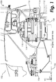
- FIG. 1 One embodiment of an engine, such as, for example, a gear-turbofan engine, is shown in partial cross-section in FIG. 1 and indicated generally at 100.
- the engine 100 comprises a PW 1000G Gear Turbofan Series engine manufactured by Pratt & Whitney®.
- a fan blade 102 is attached to a fan shaft 104 which rotates about an engine centerline 106.
- An epicyclic gear-train includes a sun gear 108, a ring gear 110, and a set of planetary gears 112 supported by a carrier frame 114.
- Each planetary gear 112 is supported by a journal bearing system.
- the planetary gear 112 rotates around a journal bearing 116 (having a journal bearing surface 118) that is supported by the carrier frame 114 at its two ends as shown in FIG. 1 .
- the engine During powered operation of the engine 100, the engine operates within a design operational speed range, and lubricant is delivered to the journal bearings 116 by means of one or multiple oil pumps (not shown).
- oil As the lubricant, those skilled in the art will recognize that any appropriate lubricant may be used, whether naturally occurring or synthetic.
- oil is squeezed by the rotation of the planetary gears 112 and generates a hydrodynamic film at the journal bearing surface 118. The hydrodynamic film is necessary to prevent undesirable metal-to-metal contact between the planetary gear 112 and the journal bearing 116. As explained above, during the non-operating condition of the engine 100, these oil pump(s) do not operate.
- auxiliary oil pump is therefore sometimes provided that is mechanically coupled to the epi-cyclic gear system so that the auxiliary oil pump will rotate with the rotation of the engine.
- wind-milling which is a phenomenon resulting from ambient wind blowing through the engine 100, may rotate the rotor below the operational speed range, causing the planetary gears 112 to rotate.
- the rotor can rotate in either the clockwise or counter-clockwise direction.
- the rotor rotates in the normal operating direction (i.e., in the clockwise direction).
- the rotor rotates in the opposite direction of the normal operating condition (i.e., in the counter-clockwise direction).
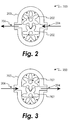
- An exemplary auxiliary oil pump comprises a positive displacement pump as schematically illustrated in FIG. 2 and indicated generally at 200.
- the pump 200 includes an internal gear system 202 that is driven by rotation of the engine rotor.
- the gear system 202 is contained within a pump housing 203.
- a first pump port 204 is formed in the pump housing 203 and is operatively connected to a supply of lubricant (not shown), such as from an auxiliary lubricant tank or from an engine lubricant sump to name two non-limiting examples.
- a second pump port 206 is formed in the pump housing 203 and is operatively coupled to supply line(s) (not shown) providing lubricant to the journal bearings 116.
- FIG. 2 illustrates operation of the pump 200 during rotation of the engine in the normal operational direction during wind-milling, which will cause rotation of the gear system 202 in the direction indicated.
- suction will be created at first pump port 204 and lubricant will be drawn into the pump 200. Additionally, lubricant under pressure will be expelled at the second pump port 206 so that it may be delivered to the journal bearings 116.
- the pump 200 will not supply lubricant to the journal bearings 116 when the engine rotates counter to the normal operational direction during wind-milling, which will cause rotation of the gear system 202 in the direction indicated in FIG. 3 .
- suction will be created at second pump port 206 and the pump 200 will attempt to draw lubricant in from the second pump port 206.
- the pump 200 will create pressure at the first pump port 204, causing any lubricant that the pump 200 is able to obtain at the second pump port 206 to be returned through the first pump port 204 to the lubricant supply.
- the pump is not supplying lubricant to the journal bearings 116 ( FIG. 1 ). If no lubricant is delivered to the journal bearings 116, the planetary gear 112 may come into direct contact with the journal bearing 116. Under this circumstance, any relative motion between the planetary gear 112 inner surface and the journal bearing surface 118 may cause premature wear and undesirable damage to either or both of these surfaces.
- a bi-directional auxiliary pump according to an embodiment is schematically illustrated and indicated generally at 300.
- the rotor speed under a wind-milling condition is a fraction of the engine operational speed range, therefore the bi-directional pump 300 disclosed herein is configured to operate below the operational speed range.
- the pump 300 will supply lubricant to the journal bearing 116 regardless of which direction the engine rotates.
- the pump 300 comprises an internal gear system 202 that is driven by rotation of the engine.
- FIG. 5 illustrates in greater detail how the pump 300 is powered by the fan shaft 104. Power is extracted from the fan shaft 104 through a gear train 350 to bring the speed of the bi-directional pump 300 to its optimum operational speed through a chosen gear ratio, as explained below.
- the engine fan shaft 104 includes a shaft gear 351 that drives an idler gear 352.
- the idler gear 352 in turns meshes with a driving gear 354 that forms part of the driving mechanism of the pump 300.
- the driving gear 354 rotates about the pump rotor centerline 356.
- the overall gear ratio of the idler gear 352 and driving gear 354 is selected to transition between an expected fan wind-milling speed range, which is much less than the operational speed range of the engine, and the speed at which the pump operates at optimum efficiency.
- the pump may be disengaged from the engine fan shaft 104 when the engine is in an operational mode.
- An operational mode may be indicated by the engine being in a running state and producing power.
- the pump may be disengaged when an Engine-Start button is activated, indicating that the engine is being placed into a running state, to name just one non-limiting example.
- An operational mode may also be indicated by the engine operating within a predetermined operational speed range.
- the pump 300 may be disengaged when it is determined that the engine is not (or soon will not be) below the operational speed range, such as by using a spring mechanism (not shown) reacting to centrifugal force at a pre-determined disengagement speed, to name just one non-limiting example. It will be appreciated from the present disclosure that the means used to disengage the pump when the engine is in a non-operational mode may vary.
- the gear system 202 within the pump 300 is contained within a pump housing 203.
- a first pump port 204 is formed in the pump housing 203 and is operatively connected to a valve outlet 302 of a check valve 304.
- a valve inlet 306 of check valve 304 is operatively coupled to a pump inlet 307 which is operatively coupled to a supply of lubricant (not shown), such as from an auxiliary lubricant tank or from an engine lubricant sump to name two non-limiting examples.
- the first pump port 204 is further operatively coupled to a valve inlet 308 of a check valve 310.
- a valve outlet 312 of check valve 310 is operatively coupled to a pump outlet 313 that is operatively coupled to supply line(s) (not shown) providing lubricant to the journal bearings 116.
- Check valves 304 and 310 function to allow flow moving in a first direction from their respective valve inlets to their respective valve outlets, while blocking (or substantially blocking) flow moving in a second direction from their respective valve outlets to their respective valve inlets.
- a second pump port 206 is formed in the pump housing 203 and is operatively coupled to a valve inlet 314 of a check valve 316.
- a valve outlet 318 of check valve 316 is operatively coupled to pump outlet 313.
- the second pump port 206 is further operatively coupled to a valve outlet 320 of a check valve 322.
- a valve inlet 324 of check valve 322 is operatively coupled to the pump inlet 307.
- Check valves 316 and 322 function to allow flow moving in a first direction from their respective valve inlets to their respective valve outlets, while blocking (or substantially blocking) flow moving in a second direction from their respective valve outlets to their respective valve inlets.
- FIG. 4 illustrates operation of the pump 300 during rotation of the engine in the normal operational direction during wind-milling, which will cause rotation of the gear system 202 in the direction indicated.
- suction will be created at first pump port 204 and lubricant will be drawn into the pump 300 through the pump inlet 307 and check valve 304.
- lubricant under pressure will be expelled at the second pump port 206 and will pass through the check valve 316 and the pump outlet 313 so that it may be delivered to the journal bearings 116.
- the high pressure flow at the second pump port 206 is prevented from reaching the low pressure first pump port 204 by operation of the check valve 322.
- the high pressure flow at the valve outlet 318 of check valve 316 is prevented from reaching the low pressure first pump port 204 by operation of the check valve 310.
- FIG. 6 illustrates operation of the pump 300 during rotation of the engine in a direction opposite to the normal operational direction during wind-milling, which will cause rotation of the gear system 202 in the direction indicated.
- suction will be created at second pump port 206 and lubricant will be drawn into the pump 300 from pump inlet 307 through the check valve 322.
- lubricant under pressure will be expelled at the first pump port 204 and will pass through the check valve 310 and pump outlet 313 so that it may be delivered to the journal bearings 116.
- the high pressure flow at the valve outlet 312 of check valve 310 is prevented from reaching the low pressure second pump port 206 by operation of the check valve 316.
- the high pressure flow at the first pump port 204 is prevented from reaching the low pressure second pump port 206 by operation of the check valve 304.
- the pump 300 When used as an auxiliary lubricant pump to supply lubricant to the journal bearings 116 during wind-milling operation of an engine, the pump 300 will supply lubricant regardless of whether the engine is being rotated by wind blowing toward the fan blade 102 through the nacelle, or toward the turbine blade through the exhaust duct of the engine. It will be appreciated by those skilled in the art in view of the present disclosure that the pump 300 may be any kind of positive displacement pump in which changing the direction of rotation also changes the direction of flow of liquid through the pump.
- the pump 300 may comprise a single-stage or multi-stage gear pump, to name two non-limiting examples.
- the check valves 304, 310, 316 and 322 may be coupled to the pump 300 using any appropriate external lines.
- one or more of the check valves 304, 310, 316 and 322 may be formed integrally with the pump housing 203.
Landscapes
- Engineering & Computer Science (AREA)
- General Engineering & Computer Science (AREA)
- Mechanical Engineering (AREA)
- Chemical & Material Sciences (AREA)
- Combustion & Propulsion (AREA)
- General Details Of Gearings (AREA)
- Rotary Pumps (AREA)
Claims (6)
- Moteur à double flux (100), comprenant :un ventilateur ;un arbre de ventilateur (104) couplé de manière opérationnelle au ventilateur ;un engrenage comportant une surface de palier d'engrenage, l'engrenage étant entraîné de manière opérationnelle par l'arbre de ventilateur ; etune pompe (200 ; 300) entraînée de manière opérationnelle par l'engrenage, la pompe comportant un premier orifice de pompe (204) et un second orifice de pompe (206), dans lequel la pompe (200 ; 300) comprend une pompe volumétrique et la pompe volumétrique comprend une première pluralité de clapets anti-retour (304 ; 310) couplés de manière opérationnelle au premier orifice de pompe (204) et une seconde pluralité de clapets anti-retour (316 ; 322) couplés de manière opérationnelle au second orifice de pompe (206) ;caractérisé en ce que la rotation de l'arbre de ventilateur dans chaque direction amène la pompe à transférer du lubrifiant vers la surface de palier d'engrenage, soit par l'intermédiaire du premier orifice de pompe lorsque l'engrenage tourne en sens horaire soit par l'intermédiaire du second orifice de pompe lorsque l'engrenage tourne en sens antihoraire, lorsque le moteur est dans un mode non opérationnel ; eten ce que la première pluralité de clapets anti-retour (304 ; 310) comprend :un premier clapet anti-retour (304) comprenant :une première entrée de clapet (306) ; etune première sortie de clapet (302) ;dans lequel la première sortie de clapet est couplée de manière opérationnelle au premier orifice de pompe (204) ;un deuxième clapet anti-retour (310) comprenant :une deuxième entrée de clapet (308) ; etune deuxième sortie de clapet (312) ;dans lequel la deuxième entrée de clapet est couplée de manière opérationnelle au premier orifice de pompe ;la seconde pluralité de clapets anti-retour (316 ; 322) comprend :
un troisième clapet anti-retour (316) comprenant :une troisième entrée de clapet (314) ; etune troisième sortie de clapet (318) ;dans lequel la troisième entrée de clapet est couplée de manière opérationnelle au second orifice de pompe (206) ; etun quatrième clapet anti-retour (322) comprenant :une quatrième entrée de clapet (324) ; etune quatrième sortie de clapet (320) ;dans lequel la quatrième sortie de clapet est couplée de manière opérationnelle au second orifice de pompe. - Moteur à double flux (100) selon la revendication 1, dans lequel l'engrenage comprend :un pignon fou (352) entraîné directement par l'arbre de ventilateur (104) ; etun engrenage d'entraînement (354) entraîné par le pignon fou, l'engrenage d'entraînement étant couplé à la pompe (200 ; 300) pour la rotation de la pompe lorsque l'engrenage d'entraînement est amené à tourner.
- Moteur à double flux (100) selon la revendication 1, comprenant en outre :une entrée de pompe (307) couplée de manière opérationnelle à la première entrée de clapet (306) et à la quatrième entrée de clapet (324) ; etune sortie de pompe (313) couplée de manière opérationnelle à la deuxième sortie de clapet (312) et à la troisième sortie de clapet (318).
- Moteur à double flux (100) selon la revendication 1, 2 ou 3, comprenant en outre :un boîtier de pompe (203) ;dans lequel la première pluralité de clapets anti-retour (304 ; 310) et la seconde pluralité de clapets anti-retour (316 ; 322) sont disposés dans le boîtier de pompe.
- Moteur à double flux (100) selon une quelconque revendication précédente, dans lequel le lubrifiant comprend de l'huile.
- Moteur à double flux (100) selon une quelconque revendication précédente, dans lequel le mode non opérationnel comprend le fait de ne pas être dans un état de marche et de ne pas produire d'énergie ; ou
le mode non opérationnel comprend le non-fonctionnement dans une plage de vitesse opérationnelle prédéterminée.
Priority Applications (2)
| Application Number | Priority Date | Filing Date | Title |
|---|---|---|---|
| EP23198391.7A EP4273374A3 (fr) | 2013-07-15 | 2014-07-10 | Lubrification de palier lisse pendant une rotation en sens horaire et en sens horaire |
| EP20196529.0A EP3779148B1 (fr) | 2013-07-15 | 2014-07-10 | Lubrification d'un palier lisse pendant une rotation en sens horaire et en sens antihoraire |
Applications Claiming Priority (2)
| Application Number | Priority Date | Filing Date | Title |
|---|---|---|---|
| US201361846280P | 2013-07-15 | 2013-07-15 | |
| PCT/US2014/046123 WO2015009535A1 (fr) | 2013-07-15 | 2014-07-10 | Lubrification d'un palier lisse pendant une rotation en sens horaire et en sens antihoraire |
Related Child Applications (3)
| Application Number | Title | Priority Date | Filing Date |
|---|---|---|---|
| EP23198391.7A Division EP4273374A3 (fr) | 2013-07-15 | 2014-07-10 | Lubrification de palier lisse pendant une rotation en sens horaire et en sens horaire |
| EP20196529.0A Division EP3779148B1 (fr) | 2013-07-15 | 2014-07-10 | Lubrification d'un palier lisse pendant une rotation en sens horaire et en sens antihoraire |
| EP20196529.0A Division-Into EP3779148B1 (fr) | 2013-07-15 | 2014-07-10 | Lubrification d'un palier lisse pendant une rotation en sens horaire et en sens antihoraire |
Publications (4)
| Publication Number | Publication Date |
|---|---|
| EP3022420A1 EP3022420A1 (fr) | 2016-05-25 |
| EP3022420A4 EP3022420A4 (fr) | 2017-04-12 |
| EP3022420B1 true EP3022420B1 (fr) | 2020-09-23 |
| EP3022420B8 EP3022420B8 (fr) | 2020-11-04 |
Family
ID=50481738
Family Applications (3)
| Application Number | Title | Priority Date | Filing Date |
|---|---|---|---|
| EP20196529.0A Active EP3779148B1 (fr) | 2013-07-15 | 2014-07-10 | Lubrification d'un palier lisse pendant une rotation en sens horaire et en sens antihoraire |
| EP23198391.7A Pending EP4273374A3 (fr) | 2013-07-15 | 2014-07-10 | Lubrification de palier lisse pendant une rotation en sens horaire et en sens horaire |
| EP14825907.0A Active EP3022420B8 (fr) | 2013-07-15 | 2014-07-10 | Lubrification d'un palier lisse pendant une rotation en sens horaire et en sens antihoraire |
Family Applications Before (2)
| Application Number | Title | Priority Date | Filing Date |
|---|---|---|---|
| EP20196529.0A Active EP3779148B1 (fr) | 2013-07-15 | 2014-07-10 | Lubrification d'un palier lisse pendant une rotation en sens horaire et en sens antihoraire |
| EP23198391.7A Pending EP4273374A3 (fr) | 2013-07-15 | 2014-07-10 | Lubrification de palier lisse pendant une rotation en sens horaire et en sens horaire |
Country Status (3)
| Country | Link |
|---|---|
| US (3) | US8702373B1 (fr) |
| EP (3) | EP3779148B1 (fr) |
| WO (1) | WO2015009535A1 (fr) |
Families Citing this family (44)
| Publication number | Priority date | Publication date | Assignee | Title |
|---|---|---|---|---|
| US8702373B1 (en) | 2013-07-15 | 2014-04-22 | United Technologies Corporation | Lubrication of journal bearing during clockwise and counter-clockwise rotation |
| WO2015060912A2 (fr) | 2013-09-19 | 2015-04-30 | United Technologies Corporation | Pompe de moulinet à deux directions pour turboréacteur à engrenages |
| FR3020410B1 (fr) * | 2014-04-29 | 2021-09-17 | Snecma | Turbomachine d'aeronef a prelevement de puissance mecanique ameliore |
| US9416866B2 (en) * | 2014-07-17 | 2016-08-16 | Baldor Electric Company | Vertical gear motor planetary gear lubrication system |
| US9528596B2 (en) | 2014-08-06 | 2016-12-27 | Baldor Electric Company | Gear box with clutch having spring engagement and hydraulic disengagement |
| US9797499B2 (en) | 2014-08-12 | 2017-10-24 | Baldor Electric Company | Method of installing a motor on a gear box |
| US9528594B2 (en) | 2014-09-04 | 2016-12-27 | Baldor Electric Company | Lubrication system for a gear box and associated methods |
| US10161408B2 (en) * | 2015-10-29 | 2018-12-25 | United Technologies Corporation | Manhattan dual FDGS aux pump design |
| US10570824B2 (en) | 2015-11-23 | 2020-02-25 | United Technologies Corporation | Near zero velocity lubrication system for a turbine engine |
| US10087849B2 (en) * | 2016-04-08 | 2018-10-02 | United Technologies Corporation | Retention device for speed change mechanism in a gas turbine engine |
| DE102017108333A1 (de) * | 2017-04-19 | 2018-10-25 | Rolls-Royce Deutschland Ltd & Co Kg | Getriebevorrichtung |
| US10787930B2 (en) | 2018-03-23 | 2020-09-29 | Raytheon Technologies Corporation | Windmill lubrication gear train for lubricant system in a geared gas turbine engine |
| US12259036B2 (en) | 2018-04-20 | 2025-03-25 | Rtx Corporation | Electric motor driven auxiliary oil system for geared gas turbine engine |
| GB201807203D0 (en) * | 2018-05-02 | 2018-06-13 | Rolls Royce Plc | Oil tank filling system |
| US10982678B2 (en) | 2018-05-21 | 2021-04-20 | Raytheon Technologies Corporation | Epicyclic drive for gas turbine engine lubricant pump |
| US11754054B2 (en) * | 2018-06-25 | 2023-09-12 | Vestas Wind Systems A/S | Pump system for lubricating components of a wind turbine |
| US11306812B2 (en) | 2018-09-28 | 2022-04-19 | Ge Avio S.R.L. | System and method for emergency lubricant flow at an aircraft gear assembly |
| CN109578143B (zh) * | 2018-12-10 | 2020-02-04 | 中国航发南方工业有限公司 | 传动盒抽油装置 |
| US11162494B2 (en) * | 2019-01-23 | 2021-11-02 | Pratt & Whitney Canada Corp. | Scavenge pump |
| FR3098258B1 (fr) | 2019-07-03 | 2021-07-16 | Safran Aircraft Engines | Pompe à engrenages basculante pour turbomachine, incorporable à un circuit de lubrification de moteur d’aéronef |
| FR3098240B1 (fr) * | 2019-07-03 | 2021-07-16 | Safran Aircraft Engines | Agencement de turbomachines d’aeronautique comprenant une pompe de lubrification entrainee par deux engrenages d’angle droit |
| FR3106623B1 (fr) * | 2020-01-23 | 2022-10-07 | Safran Aircraft Engines | Dispositif de lubrification pour une turbomachine d’aéronef, à circulation de lubrifiant dans les deux sens de rotation d’une pompe |
| GB2592008A (en) * | 2020-02-11 | 2021-08-18 | Rolls Royce Plc | System for supplying lubricant to a component |
| FR3108936B1 (fr) * | 2020-04-01 | 2022-02-25 | Safran Aircraft Engines | Ensemble pour turbomachine comprenant une pompe de lubrification |
| GB202005916D0 (en) * | 2020-04-23 | 2020-06-10 | Rolls Royce Plc | Gas turbine engine lubrication system |
| WO2022058442A1 (fr) | 2020-09-18 | 2022-03-24 | Vcst Industrial Products Bv | Pompe volumétrique bidirectionnelle |
| US12320418B2 (en) * | 2022-06-22 | 2025-06-03 | General Electric Company | Gearbox assembly with lubricant extraction volume ratio |
| US12326115B2 (en) * | 2022-06-22 | 2025-06-10 | General Electric Company | Gearbox assembly with lubricant extraction volume ratio |
| US12276228B2 (en) | 2022-07-27 | 2025-04-15 | General Electric Company | Planet gear clearances in epicyclic gearboxes |
| US12516627B2 (en) | 2022-07-27 | 2026-01-06 | General Electric Company | Gas turbine engine |
| US12584446B2 (en) | 2023-06-21 | 2026-03-24 | General Electric Company | Unidirectional fan brake for a gas turbine engine |
| US12276333B2 (en) * | 2023-06-21 | 2025-04-15 | General Electric Company | Gearbox assembly lubrication system for a turbine engine |
| US12510002B2 (en) * | 2023-07-12 | 2025-12-30 | General Electric Company | Lubrication system for a turbine engine |
| US12228042B1 (en) * | 2023-08-04 | 2025-02-18 | General Electric Company | Lubrication system for a turbine engine |
| CN117052500A (zh) * | 2023-09-20 | 2023-11-14 | 大连鼎力交通轨道设备有限公司 | 一种可以实现正反转双向流量内燃机车用启动机油泵 |
| IT202300021018A1 (it) * | 2023-10-10 | 2025-04-10 | Ge Avio Srl | Impianto di lubrificazione per un motore a turbina |
| CN119801730A (zh) | 2023-10-10 | 2025-04-11 | 通用电气阿维奥有限责任公司 | 用于涡轮发动机的润滑系统 |
| IT202300021060A1 (it) * | 2023-10-10 | 2025-04-10 | Ge Avio Srl | Impianto di lubrificazione per un motore a turbina |
| CN119801731A (zh) | 2023-10-10 | 2025-04-11 | 通用电气阿维奥有限责任公司 | 用于涡轮发动机的润滑系统 |
| IT202400002647A1 (it) | 2024-02-08 | 2025-08-08 | Ge Avio Srl | Gruppo di trasmissione ad ingranaggi avente un sistema di frenatura di ingranaggi |
| IT202400002653A1 (it) | 2024-02-08 | 2025-08-08 | Ge Avio Srl | Gruppo di trasmissione ad ingranaggi per un motore a turbina |
| US12516724B2 (en) | 2024-04-04 | 2026-01-06 | General Electric Company | Systems and methods for heating a gearbox prior to fan rotation |
| US12492649B2 (en) | 2024-05-06 | 2025-12-09 | General Electric Company | Lubrication system and methods of lubricating a gearbox assembly |
| EP4686817A1 (fr) * | 2024-08-02 | 2026-02-04 | RTX Corporation | Systèmes de gestion thermique de turbine à gaz comprenant une pompe bidirectionnelle |
Family Cites Families (15)
| Publication number | Priority date | Publication date | Assignee | Title |
|---|---|---|---|---|
| US2860713A (en) * | 1952-10-09 | 1958-11-18 | Gen Motors Corp | Power transmission system |
| JP3519544B2 (ja) * | 1996-05-17 | 2004-04-19 | 愛知機械工業株式会社 | 電気自動車用減速機のオイルポンプ周り液路 |
| JP2006105029A (ja) * | 2004-10-06 | 2006-04-20 | Hitachi Ltd | オイルポンプ |
| US7621117B2 (en) * | 2006-06-19 | 2009-11-24 | Pratt & Whitney Canada Corp. | Apparatus and method for controlling engine windmilling |
| DE102006039608A1 (de) * | 2006-08-24 | 2008-04-10 | Rolls-Royce Deutschland Ltd & Co Kg | Anordnung zur Energieentnahme bei einem Zwei-Wellen-Triebwerk |
| US7662059B2 (en) * | 2006-10-18 | 2010-02-16 | United Technologies Corporation | Lubrication of windmilling journal bearings |
| US7849668B2 (en) * | 2006-10-25 | 2010-12-14 | United Technologies Corporation | Rotor brake and windmilling lubrication system for geared turbofan engine |
| DE102008022383B4 (de) * | 2008-05-06 | 2016-01-21 | Senvion Gmbh | Positionierung eines Rotors einer Windenergieanlage |
| US8307626B2 (en) * | 2009-02-26 | 2012-11-13 | United Technologies Corporation | Auxiliary pump system for fan drive gear system |
| US8230974B2 (en) * | 2009-05-22 | 2012-07-31 | United Technologies Corporation | Windmill and zero gravity lubrication system for a gas turbine engine |
| US8381878B2 (en) * | 2009-11-12 | 2013-02-26 | United Technologies Corporation | Oil capture and bypass system |
| DE102011055194B4 (de) | 2011-11-10 | 2018-01-18 | Gkn Walterscheid Gmbh | Hydraulikpumpenanordnung |
| US9970352B2 (en) * | 2012-01-27 | 2018-05-15 | United Technologies Corporation | Turbomachine fan clutch |
| WO2014133669A1 (fr) | 2013-02-26 | 2014-09-04 | United Technologies Corporation | Lubrification d'un palier lisse durant une rotation en sens horaire et en sens antihoraire |
| US8702373B1 (en) | 2013-07-15 | 2014-04-22 | United Technologies Corporation | Lubrication of journal bearing during clockwise and counter-clockwise rotation |
-
2013
- 2013-08-29 US US14/013,952 patent/US8702373B1/en active Active
-
2014
- 2014-07-10 EP EP20196529.0A patent/EP3779148B1/fr active Active
- 2014-07-10 US US14/905,528 patent/US10577974B2/en active Active
- 2014-07-10 EP EP23198391.7A patent/EP4273374A3/fr active Pending
- 2014-07-10 WO PCT/US2014/046123 patent/WO2015009535A1/fr not_active Ceased
- 2014-07-10 EP EP14825907.0A patent/EP3022420B8/fr active Active
-
2019
- 2019-08-29 US US16/555,358 patent/US11092037B2/en active Active
Non-Patent Citations (1)
| Title |
|---|
| None * |
Also Published As
| Publication number | Publication date |
|---|---|
| US20160146048A1 (en) | 2016-05-26 |
| EP3022420A1 (fr) | 2016-05-25 |
| WO2015009535A1 (fr) | 2015-01-22 |
| EP3022420A4 (fr) | 2017-04-12 |
| US10577974B2 (en) | 2020-03-03 |
| EP3779148A3 (fr) | 2021-04-21 |
| EP4273374A3 (fr) | 2023-11-29 |
| US8702373B1 (en) | 2014-04-22 |
| US11092037B2 (en) | 2021-08-17 |
| EP3022420B8 (fr) | 2020-11-04 |
| EP4273374A2 (fr) | 2023-11-08 |
| US20190383168A1 (en) | 2019-12-19 |
| EP3779148A2 (fr) | 2021-02-17 |
| EP3779148B1 (fr) | 2023-09-20 |
Similar Documents
| Publication | Publication Date | Title |
|---|---|---|
| EP3022420B1 (fr) | Lubrification d'un palier lisse pendant une rotation en sens horaire et en sens antihoraire | |
| US10208624B2 (en) | Lubrication of journal bearing during clockwise and counter-clockwise rotation | |
| EP2224120B1 (fr) | Pompe de lubrification auxiliaire pour train de transmission à engrenages de turboréacteur | |
| JP4903662B2 (ja) | 遊星歯車装置およびタービンエンジン | |
| US9062611B2 (en) | Split accessory drive system | |
| US10196926B2 (en) | Lubricating a rotating component during forward and/or reverse rotation | |
| EP3171055B1 (fr) | Système de lubrification de vitesse proche de zéro pour moteur à turbine | |
| EP3075966B1 (fr) | Moteur à turbine à gaz comprenant un système de démarrage de turbine à air avec un module d'embrayage intégré dans la boîte de vitesses | |
| CN109469724B (zh) | 用于旋转组件的辅助供油设备 | |
| JP2007518615A (ja) | プロペラエンジン装置用の加圧オイル供給 | |
| EP3299674B1 (fr) | Capteur de niveau d'huile pour une boîte de vitesses | |
| CN106285947B (zh) | 用于涡轮发动机的泵 | |
| US9371000B2 (en) | Transmission having integrated transmission pump and accessory drive | |
| US20180259060A1 (en) | Use of metering hole in shroud of splash-lubricated gearbox for disbursing lubricant within gearbox | |
| US20250361821A1 (en) | Integrated in-line emergency lube pump assembly for planetary gearbox configurations | |
| CN205260738U (zh) | 一种传动装置和风力发电机 |
Legal Events
| Date | Code | Title | Description |
|---|---|---|---|
| PUAI | Public reference made under article 153(3) epc to a published international application that has entered the european phase |
Free format text: ORIGINAL CODE: 0009012 |
|
| 17P | Request for examination filed |
Effective date: 20160211 |
|
| AK | Designated contracting states |
Kind code of ref document: A1 Designated state(s): AL AT BE BG CH CY CZ DE DK EE ES FI FR GB GR HR HU IE IS IT LI LT LU LV MC MK MT NL NO PL PT RO RS SE SI SK SM TR |
|
| AX | Request for extension of the european patent |
Extension state: BA ME |
|
| DAX | Request for extension of the european patent (deleted) | ||
| RAP1 | Party data changed (applicant data changed or rights of an application transferred) |
Owner name: UNITED TECHNOLOGIES CORPORATION |
|
| A4 | Supplementary search report drawn up and despatched |
Effective date: 20170314 |
|
| RIC1 | Information provided on ipc code assigned before grant |
Ipc: F02C 7/06 20060101AFI20170308BHEP Ipc: F02C 7/32 20060101ALI20170308BHEP Ipc: F01D 25/20 20060101ALI20170308BHEP Ipc: F16H 57/04 20100101ALI20170308BHEP Ipc: F02C 7/36 20060101ALI20170308BHEP Ipc: F01M 1/02 20060101ALI20170308BHEP |
|
| STAA | Information on the status of an ep patent application or granted ep patent |
Free format text: STATUS: EXAMINATION IS IN PROGRESS |
|
| 17Q | First examination report despatched |
Effective date: 20180921 |
|
| GRAP | Despatch of communication of intention to grant a patent |
Free format text: ORIGINAL CODE: EPIDOSNIGR1 |
|
| STAA | Information on the status of an ep patent application or granted ep patent |
Free format text: STATUS: GRANT OF PATENT IS INTENDED |
|
| INTG | Intention to grant announced |
Effective date: 20200430 |
|
| GRAS | Grant fee paid |
Free format text: ORIGINAL CODE: EPIDOSNIGR3 |
|
| GRAA | (expected) grant |
Free format text: ORIGINAL CODE: 0009210 |
|
| STAA | Information on the status of an ep patent application or granted ep patent |
Free format text: STATUS: THE PATENT HAS BEEN GRANTED |
|
| AK | Designated contracting states |
Kind code of ref document: B1 Designated state(s): AL AT BE BG CH CY CZ DE DK EE ES FI FR GB GR HR HU IE IS IT LI LT LU LV MC MK MT NL NO PL PT RO RS SE SI SK SM TR |
|
| REG | Reference to a national code |
Ref country code: GB Ref legal event code: FG4D |
|
| REG | Reference to a national code |
Ref country code: CH Ref legal event code: EP |
|
| REG | Reference to a national code |
Ref country code: DE Ref legal event code: R081 Ref document number: 602014070558 Country of ref document: DE Owner name: RAYTHEON TECHNOLOGIES CORPORATION, FARMINGTON, US Free format text: FORMER OWNER: UNITED TECHNOLOGIES CORPORATION, FARMINGTON, CONN., US |
|
| RAP2 | Party data changed (patent owner data changed or rights of a patent transferred) |
Owner name: RAYTHEON TECHNOLOGIES CORPORATION |
|
| REG | Reference to a national code |
Ref country code: IE Ref legal event code: FG4D |
|
| REG | Reference to a national code |
Ref country code: CH Ref legal event code: PK Free format text: BERICHTIGUNG B8 Ref country code: DE Ref legal event code: R096 Ref document number: 602014070558 Country of ref document: DE Ref country code: AT Ref legal event code: REF Ref document number: 1316593 Country of ref document: AT Kind code of ref document: T Effective date: 20201015 |
|
| PG25 | Lapsed in a contracting state [announced via postgrant information from national office to epo] |
Ref country code: SE Free format text: LAPSE BECAUSE OF FAILURE TO SUBMIT A TRANSLATION OF THE DESCRIPTION OR TO PAY THE FEE WITHIN THE PRESCRIBED TIME-LIMIT Effective date: 20200923 Ref country code: NO Free format text: LAPSE BECAUSE OF FAILURE TO SUBMIT A TRANSLATION OF THE DESCRIPTION OR TO PAY THE FEE WITHIN THE PRESCRIBED TIME-LIMIT Effective date: 20201223 Ref country code: HR Free format text: LAPSE BECAUSE OF FAILURE TO SUBMIT A TRANSLATION OF THE DESCRIPTION OR TO PAY THE FEE WITHIN THE PRESCRIBED TIME-LIMIT Effective date: 20200923 Ref country code: BG Free format text: LAPSE BECAUSE OF FAILURE TO SUBMIT A TRANSLATION OF THE DESCRIPTION OR TO PAY THE FEE WITHIN THE PRESCRIBED TIME-LIMIT Effective date: 20201223 Ref country code: GR Free format text: LAPSE BECAUSE OF FAILURE TO SUBMIT A TRANSLATION OF THE DESCRIPTION OR TO PAY THE FEE WITHIN THE PRESCRIBED TIME-LIMIT Effective date: 20201224 Ref country code: FI Free format text: LAPSE BECAUSE OF FAILURE TO SUBMIT A TRANSLATION OF THE DESCRIPTION OR TO PAY THE FEE WITHIN THE PRESCRIBED TIME-LIMIT Effective date: 20200923 |
|
| REG | Reference to a national code |
Ref country code: AT Ref legal event code: MK05 Ref document number: 1316593 Country of ref document: AT Kind code of ref document: T Effective date: 20200923 |
|
| PG25 | Lapsed in a contracting state [announced via postgrant information from national office to epo] |
Ref country code: LV Free format text: LAPSE BECAUSE OF FAILURE TO SUBMIT A TRANSLATION OF THE DESCRIPTION OR TO PAY THE FEE WITHIN THE PRESCRIBED TIME-LIMIT Effective date: 20200923 Ref country code: RS Free format text: LAPSE BECAUSE OF FAILURE TO SUBMIT A TRANSLATION OF THE DESCRIPTION OR TO PAY THE FEE WITHIN THE PRESCRIBED TIME-LIMIT Effective date: 20200923 |
|
| REG | Reference to a national code |
Ref country code: NL Ref legal event code: MP Effective date: 20200923 |
|
| REG | Reference to a national code |
Ref country code: LT Ref legal event code: MG4D |
|
| PG25 | Lapsed in a contracting state [announced via postgrant information from national office to epo] |
Ref country code: CZ Free format text: LAPSE BECAUSE OF FAILURE TO SUBMIT A TRANSLATION OF THE DESCRIPTION OR TO PAY THE FEE WITHIN THE PRESCRIBED TIME-LIMIT Effective date: 20200923 Ref country code: PT Free format text: LAPSE BECAUSE OF FAILURE TO SUBMIT A TRANSLATION OF THE DESCRIPTION OR TO PAY THE FEE WITHIN THE PRESCRIBED TIME-LIMIT Effective date: 20210125 Ref country code: NL Free format text: LAPSE BECAUSE OF FAILURE TO SUBMIT A TRANSLATION OF THE DESCRIPTION OR TO PAY THE FEE WITHIN THE PRESCRIBED TIME-LIMIT Effective date: 20200923 Ref country code: LT Free format text: LAPSE BECAUSE OF FAILURE TO SUBMIT A TRANSLATION OF THE DESCRIPTION OR TO PAY THE FEE WITHIN THE PRESCRIBED TIME-LIMIT Effective date: 20200923 Ref country code: EE Free format text: LAPSE BECAUSE OF FAILURE TO SUBMIT A TRANSLATION OF THE DESCRIPTION OR TO PAY THE FEE WITHIN THE PRESCRIBED TIME-LIMIT Effective date: 20200923 Ref country code: SM Free format text: LAPSE BECAUSE OF FAILURE TO SUBMIT A TRANSLATION OF THE DESCRIPTION OR TO PAY THE FEE WITHIN THE PRESCRIBED TIME-LIMIT Effective date: 20200923 Ref country code: RO Free format text: LAPSE BECAUSE OF FAILURE TO SUBMIT A TRANSLATION OF THE DESCRIPTION OR TO PAY THE FEE WITHIN THE PRESCRIBED TIME-LIMIT Effective date: 20200923 |
|
| PG25 | Lapsed in a contracting state [announced via postgrant information from national office to epo] |
Ref country code: ES Free format text: LAPSE BECAUSE OF FAILURE TO SUBMIT A TRANSLATION OF THE DESCRIPTION OR TO PAY THE FEE WITHIN THE PRESCRIBED TIME-LIMIT Effective date: 20200923 Ref country code: AL Free format text: LAPSE BECAUSE OF FAILURE TO SUBMIT A TRANSLATION OF THE DESCRIPTION OR TO PAY THE FEE WITHIN THE PRESCRIBED TIME-LIMIT Effective date: 20200923 Ref country code: AT Free format text: LAPSE BECAUSE OF FAILURE TO SUBMIT A TRANSLATION OF THE DESCRIPTION OR TO PAY THE FEE WITHIN THE PRESCRIBED TIME-LIMIT Effective date: 20200923 Ref country code: PL Free format text: LAPSE BECAUSE OF FAILURE TO SUBMIT A TRANSLATION OF THE DESCRIPTION OR TO PAY THE FEE WITHIN THE PRESCRIBED TIME-LIMIT Effective date: 20200923 Ref country code: IS Free format text: LAPSE BECAUSE OF FAILURE TO SUBMIT A TRANSLATION OF THE DESCRIPTION OR TO PAY THE FEE WITHIN THE PRESCRIBED TIME-LIMIT Effective date: 20210123 |
|
| REG | Reference to a national code |
Ref country code: DE Ref legal event code: R097 Ref document number: 602014070558 Country of ref document: DE |
|
| PG25 | Lapsed in a contracting state [announced via postgrant information from national office to epo] |
Ref country code: SK Free format text: LAPSE BECAUSE OF FAILURE TO SUBMIT A TRANSLATION OF THE DESCRIPTION OR TO PAY THE FEE WITHIN THE PRESCRIBED TIME-LIMIT Effective date: 20200923 |
|
| PLBE | No opposition filed within time limit |
Free format text: ORIGINAL CODE: 0009261 |
|
| STAA | Information on the status of an ep patent application or granted ep patent |
Free format text: STATUS: NO OPPOSITION FILED WITHIN TIME LIMIT |
|
| PG25 | Lapsed in a contracting state [announced via postgrant information from national office to epo] |
Ref country code: SI Free format text: LAPSE BECAUSE OF FAILURE TO SUBMIT A TRANSLATION OF THE DESCRIPTION OR TO PAY THE FEE WITHIN THE PRESCRIBED TIME-LIMIT Effective date: 20200923 Ref country code: DK Free format text: LAPSE BECAUSE OF FAILURE TO SUBMIT A TRANSLATION OF THE DESCRIPTION OR TO PAY THE FEE WITHIN THE PRESCRIBED TIME-LIMIT Effective date: 20200923 |
|
| 26N | No opposition filed |
Effective date: 20210624 |
|
| PG25 | Lapsed in a contracting state [announced via postgrant information from national office to epo] |
Ref country code: IT Free format text: LAPSE BECAUSE OF FAILURE TO SUBMIT A TRANSLATION OF THE DESCRIPTION OR TO PAY THE FEE WITHIN THE PRESCRIBED TIME-LIMIT Effective date: 20200923 |
|
| REG | Reference to a national code |
Ref country code: CH Ref legal event code: PL |
|
| PG25 | Lapsed in a contracting state [announced via postgrant information from national office to epo] |
Ref country code: MC Free format text: LAPSE BECAUSE OF FAILURE TO SUBMIT A TRANSLATION OF THE DESCRIPTION OR TO PAY THE FEE WITHIN THE PRESCRIBED TIME-LIMIT Effective date: 20200923 |
|
| REG | Reference to a national code |
Ref country code: BE Ref legal event code: MM Effective date: 20210731 |
|
| PG25 | Lapsed in a contracting state [announced via postgrant information from national office to epo] |
Ref country code: LI Free format text: LAPSE BECAUSE OF NON-PAYMENT OF DUE FEES Effective date: 20210731 Ref country code: CH Free format text: LAPSE BECAUSE OF NON-PAYMENT OF DUE FEES Effective date: 20210731 |
|
| PG25 | Lapsed in a contracting state [announced via postgrant information from national office to epo] |
Ref country code: LU Free format text: LAPSE BECAUSE OF NON-PAYMENT OF DUE FEES Effective date: 20210710 |
|
| PG25 | Lapsed in a contracting state [announced via postgrant information from national office to epo] |
Ref country code: IE Free format text: LAPSE BECAUSE OF NON-PAYMENT OF DUE FEES Effective date: 20210710 Ref country code: BE Free format text: LAPSE BECAUSE OF NON-PAYMENT OF DUE FEES Effective date: 20210731 |
|
| PG25 | Lapsed in a contracting state [announced via postgrant information from national office to epo] |
Ref country code: HU Free format text: LAPSE BECAUSE OF FAILURE TO SUBMIT A TRANSLATION OF THE DESCRIPTION OR TO PAY THE FEE WITHIN THE PRESCRIBED TIME-LIMIT; INVALID AB INITIO Effective date: 20140710 |
|
| P01 | Opt-out of the competence of the unified patent court (upc) registered |
Effective date: 20230520 |
|
| PG25 | Lapsed in a contracting state [announced via postgrant information from national office to epo] |
Ref country code: CY Free format text: LAPSE BECAUSE OF FAILURE TO SUBMIT A TRANSLATION OF THE DESCRIPTION OR TO PAY THE FEE WITHIN THE PRESCRIBED TIME-LIMIT Effective date: 20200923 |
|
| PG25 | Lapsed in a contracting state [announced via postgrant information from national office to epo] |
Ref country code: MK Free format text: LAPSE BECAUSE OF FAILURE TO SUBMIT A TRANSLATION OF THE DESCRIPTION OR TO PAY THE FEE WITHIN THE PRESCRIBED TIME-LIMIT Effective date: 20200923 |
|
| PG25 | Lapsed in a contracting state [announced via postgrant information from national office to epo] |
Ref country code: MT Free format text: LAPSE BECAUSE OF FAILURE TO SUBMIT A TRANSLATION OF THE DESCRIPTION OR TO PAY THE FEE WITHIN THE PRESCRIBED TIME-LIMIT Effective date: 20200923 |
|
| PGFP | Annual fee paid to national office [announced via postgrant information from national office to epo] |
Ref country code: GB Payment date: 20250619 Year of fee payment: 12 |
|
| PGFP | Annual fee paid to national office [announced via postgrant information from national office to epo] |
Ref country code: FR Payment date: 20250620 Year of fee payment: 12 |
|
| REG | Reference to a national code |
Ref country code: DE Ref legal event code: R081 Ref document number: 602014070558 Country of ref document: DE Owner name: RTX CORPORATION (N.D.GES.D. STAATES DELAWARE),, US Free format text: FORMER OWNER: RAYTHEON TECHNOLOGIES CORPORATION, FARMINGTON, CT, US |
|
| PGFP | Annual fee paid to national office [announced via postgrant information from national office to epo] |
Ref country code: DE Payment date: 20250620 Year of fee payment: 12 |
|
| PG25 | Lapsed in a contracting state [announced via postgrant information from national office to epo] |
Ref country code: TR Free format text: LAPSE BECAUSE OF FAILURE TO SUBMIT A TRANSLATION OF THE DESCRIPTION OR TO PAY THE FEE WITHIN THE PRESCRIBED TIME-LIMIT Effective date: 20200923 |