EP3022474B1 - Garniture en cascade pour soupape de commande - Google Patents
Garniture en cascade pour soupape de commande Download PDFInfo
- Publication number
- EP3022474B1 EP3022474B1 EP14825983.1A EP14825983A EP3022474B1 EP 3022474 B1 EP3022474 B1 EP 3022474B1 EP 14825983 A EP14825983 A EP 14825983A EP 3022474 B1 EP3022474 B1 EP 3022474B1
- Authority
- EP
- European Patent Office
- Prior art keywords
- stem
- cage
- valve
- fluid
- fluid passageway
- Prior art date
- Legal status (The legal status is an assumption and is not a legal conclusion. Google has not performed a legal analysis and makes no representation as to the accuracy of the status listed.)
- Active
Links
Images


Classifications
-
- F—MECHANICAL ENGINEERING; LIGHTING; HEATING; WEAPONS; BLASTING
- F16—ENGINEERING ELEMENTS AND UNITS; GENERAL MEASURES FOR PRODUCING AND MAINTAINING EFFECTIVE FUNCTIONING OF MACHINES OR INSTALLATIONS; THERMAL INSULATION IN GENERAL
- F16K—VALVES; TAPS; COCKS; ACTUATING-FLOATS; DEVICES FOR VENTING OR AERATING
- F16K47/00—Means in valves for absorbing fluid energy
- F16K47/08—Means in valves for absorbing fluid energy for decreasing pressure or noise level and having a throttling member separate from the closure member, e.g. screens, slots, labyrinths
-
- F—MECHANICAL ENGINEERING; LIGHTING; HEATING; WEAPONS; BLASTING
- F16—ENGINEERING ELEMENTS AND UNITS; GENERAL MEASURES FOR PRODUCING AND MAINTAINING EFFECTIVE FUNCTIONING OF MACHINES OR INSTALLATIONS; THERMAL INSULATION IN GENERAL
- F16K—VALVES; TAPS; COCKS; ACTUATING-FLOATS; DEVICES FOR VENTING OR AERATING
- F16K1/00—Lift valves or globe valves, i.e. cut-off apparatus with closure members having at least a component of their opening and closing motion perpendicular to the closing faces
- F16K1/32—Details
- F16K1/54—Arrangements for modifying the way in which the rate of flow varies during the actuation of the valve
-
- F—MECHANICAL ENGINEERING; LIGHTING; HEATING; WEAPONS; BLASTING
- F16—ENGINEERING ELEMENTS AND UNITS; GENERAL MEASURES FOR PRODUCING AND MAINTAINING EFFECTIVE FUNCTIONING OF MACHINES OR INSTALLATIONS; THERMAL INSULATION IN GENERAL
- F16K—VALVES; TAPS; COCKS; ACTUATING-FLOATS; DEVICES FOR VENTING OR AERATING
- F16K47/00—Means in valves for absorbing fluid energy
- F16K47/04—Means in valves for absorbing fluid energy for decreasing pressure or noise level, the throttle being incorporated in the closure member
- F16K47/06—Means in valves for absorbing fluid energy for decreasing pressure or noise level, the throttle being incorporated in the closure member with a throttle in the form of a helical channel
-
- F—MECHANICAL ENGINEERING; LIGHTING; HEATING; WEAPONS; BLASTING
- F16—ENGINEERING ELEMENTS AND UNITS; GENERAL MEASURES FOR PRODUCING AND MAINTAINING EFFECTIVE FUNCTIONING OF MACHINES OR INSTALLATIONS; THERMAL INSULATION IN GENERAL
- F16K—VALVES; TAPS; COCKS; ACTUATING-FLOATS; DEVICES FOR VENTING OR AERATING
- F16K47/00—Means in valves for absorbing fluid energy
- F16K47/08—Means in valves for absorbing fluid energy for decreasing pressure or noise level and having a throttling member separate from the closure member, e.g. screens, slots, labyrinths
- F16K47/12—Means in valves for absorbing fluid energy for decreasing pressure or noise level and having a throttling member separate from the closure member, e.g. screens, slots, labyrinths the throttling channel being of helical form
-
- Y—GENERAL TAGGING OF NEW TECHNOLOGICAL DEVELOPMENTS; GENERAL TAGGING OF CROSS-SECTIONAL TECHNOLOGIES SPANNING OVER SEVERAL SECTIONS OF THE IPC; TECHNICAL SUBJECTS COVERED BY FORMER USPC CROSS-REFERENCE ART COLLECTIONS [XRACs] AND DIGESTS
- Y10—TECHNICAL SUBJECTS COVERED BY FORMER USPC
- Y10T—TECHNICAL SUBJECTS COVERED BY FORMER US CLASSIFICATION
- Y10T137/00—Fluid handling
- Y10T137/8593—Systems
- Y10T137/86493—Multi-way valve unit
- Y10T137/86718—Dividing into parallel flow paths with recombining
- Y10T137/86759—Reciprocating
- Y10T137/86791—Piston
Definitions
- the present invention relates generally to flow control devices and, more particularly, to a cascade trim control valve which includes a uniquely configured valve stem and corresponding valve cage formed with complimentary flow passages which are selectively brought in and out of alignment with each other to vary the fluid control properties of the control valve.
- a cylindrical plug is moveable axially within a complimentary cylinder.
- the plug includes a fluid flow path extending axially therein. As the plug is moved axially relative to the cylinder, the area of path entry available for fluid flow and the length of the fluid flow path is varied. As a result, as the plug moves further out of the cylinder, a corresponding increase in fluid flow is obtained in the control valve.
- Another species of conventional fluid control valves generally includes a cage and a valve stem reciprocally moveable within the cage.
- the cage is typically formed from a plurality of stacked disks, which when stacked, form a plurality of tortuous flow passages between an inner surface and an outer surface.
- the valve stem When the valve stem is in a closed position, the stem typically covers all of the passages in the cage, thereby preventing fluid from flowing through the cage.
- the incremental movement of the stem from the closed position toward an open position incrementally exposes the fluid passages in the cage, thereby allowing fluid to flow therethrough.
- cavitation which may be triggered in response to certain flow conditions. Cavitation creates damage to the structure of the valve.
- Another drawback with conventional disk-stack type valves is that they tend to be ineffective when used with dirty fluids, i.e., fluids having debris/particulate in the fluid. As the fluid flows through the valve, the debris may clog the passageways within the cage, thereby altering the fluid control properties of the cage.
- the US Patent 4,634,095 discloses a choke valve with flow restriction stages for controlling fluid under high pressure.
- a stem axially moves a valve toward and away from a valve seat opening and closing a passageway through the valve.
- Slots being formed in the valve stem wall mate and mismate the flow restriction recesses in response to axial movement of the valve stem.
- the US Patent 6,076,552 discloses a valve including a spool with a land being received in a bore of a valve body. At least one transfer passage is formed in the land. According to the 6,076,552 Patent, the land and an inner wall of the bore cooperate with each other in order to prevent any passage other than the transfer passage from opening between an inlet port and an outlet port.
- the US Patent 5,113,908 discloses a trim design including a housing with a cylindrical passageway passing therethrough.
- a stepped plug is disposed between an inlet and an outlet.
- a second cage with apertures is positioned between the outlet and a first cage having axial channels for passage of fluids through the trim design.
- the flow control device or control valve constructed in accordance with the present invention represents an improvement over the control valve described in the '119 Patent, and the conventional disk-stack type valves, by virtue of its inclusion of more intricate and complex flow passages which are formed in both the valve stem and the surrounding cylinder (i.e., the cage).
- the increased intricacy/complexity of the flow passages within the control valve of the present invention provides for a better flow range/rangeability therethrough.
- a cascade trim for use in a fluid control valve in accordance with claim 1.
- the first fluid passageway column may be comprised of a twenty "stage” fluid passageway traversing through both the valve stem and the cage.
- the second fluid passageway column may be comprised of a twelve "stage” fluid passageway, also traversing through both the valve stem and the cage.
- the trim may include a pair of first fluid passageway columns arranged in diametrically opposed relation to each other. Likewise, the trim may include a pair of second fluid passageway columns arranged in diametrically opposed relation to each other.
- the trim may include a third fluid passageway column in addition to the first and second fluid passageway columns.
- the valve cage may include a discharge chamber and a valve seat defining a valve outlet, wherein the valve seat is slightly elevated above a bottom floor of the discharge chamber to allow for collection of debris/particulate in the fluid as the fluid passes through the trim.
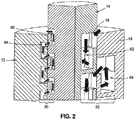
- FIG. 1 is a partial cross sectional perspective view of a fluid control valve including a cascade trim 10.
- the cascade trim 10 comprises a cage 12 and a valve stem 14 disposed within the cage 12 and reciprocally, axially movable relative thereto. Though not shown, the trim 10 will typically reside within a hollow, interior gallery or chamber defined by a housing of the control valve including the same.
- the cage 12 When viewed from the perspective shown in Figure 1 , the cage 12 includes an inlet 16 formed at the top end portion 18 (see Figure 2 ) thereof, and a discharge chamber 20 having an outlet 22 formed at the bottom end portion 24 of the cage 12.
- the inlet 16 will fluidly communicate with an inlet passage defined by the control valve housing, with the outlet 22 fluidly communicating with an outlet passage defined by the control valve housing.
- the stem 14 includes a beveled end portion 26 which interfaces with a valve seat 28 formed in the cage 12 to close the cascade trim 10, and hence the control valve including the same.
- the valve seat 28 is formed at the bottom of the cage 12, although it is also contemplated that in other embodiments, the valve seat 28 may be formed at the top of the valve cage 12.
- the stem 14 is actuated axially to lift the beveled end portion 26 off the complimentary seat 28 to open the cascade trim 10, and hence the control valve including the same.
- the movement of the stem 14 is preferably facilitated by an elongate shank which is attached to and extends axially from the top end thereof opposite the beveled end portion 26, the shank itself being cooperatively engaged to a suitable actuator.
- an exemplary control valve structure which may accommodate the trim 10 is included in Applicant's co-pending U.S. Application Serial No. 13/827,462 entitled MULTI-STAGE FLUID FLOW CONTROL DEVICE filed March 14, 2013.
- the cage 12 and stem 14 are each manufactured to include a series of passageways formed therein, such that certain ones of the cage passageways are brought into fluid communication with the corresponding ones of the stem passageways in response to axial movement of the stem 14 relative to the cage 12 to create or constitute one or more fluid passageway columns through the cascade trim 10.
- the stem 14 and cage 12 may be configured to define multiple fluid passageway columns, each of which corresponds to different axial positions of the stem 14 relative to the valve cage 12.
- Each fluid passageway column may exhibit different fluid control properties, and as such, the stem 14 may be throttled to a position corresponding to the desired fluid passageway column depending on the desired fluid control parameters.
- Figures 1 and 2 show partial cross sectional views of an exemplary stem 14 and cage 12, wherein Figure 2 is an enlarged view of the top portion of the stem 14 and cage 12 shown in Figure 1 .
- a first fluid passageway column 30 is depicted on the left side of the cascade trim 10 and a second fluid passageway column 32 is depicted on the right side of the cascade trim 10.
- the first and second passageways columns 30, 32 shown in Figures 1 and 2 are both defined by complimentary sets of openings in the cage 12 and stem 14 which have been brought into alignment with each other due to the particular placement of the stem 14 relative to the cage 12.
- Figures 1 and 2 are only partial sectional views of the cascade trim 10, it is contemplated that the complete cascade trim 10 will include mirror images of the first and second passageway columns 30, 32 in diametrically opposed relation to the columns 30, 32 depicted in Figures 1 and 2 .
- FIG. 1 shows a cross sectional view of the cage 12
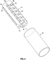
- Figure 4 depicts a perspective view of the cage 12.
- the cage 12 has a generally cylindrical configuration and includes an inner surface 34 as well as an outer surface 36, with a central bore 38 extending axially through the cage 12 from a first end portion 40 to an opposing second end portion 42 thereof.
- the cage 12 includes a plurality of passageways formed therein, wherein the passageways define respective portions of the first and second fluid passageway columns 30, 32.
- the cage passageways used in forming the first fluid passageway column 30 will be referred to herein as the first cage passageways 44, while the cage passageways used in forming the second fluid passageway column 32 will be referred to herein as the second cage passageways 46.
- first cage passageways 44 are depicted in the cross-sectional plane as small, generally U-shaped channels having openings 48 in communication with the central bore 38.
- the first cage passageways 44 are arranged in two diametrically opposed arrays.
- the second cage passageways 46 are associated with the large, generally quadrangular-shaped openings 50 arranged in two-parallel arrays of six openings. Although only a cross section is shown in Figure 3 , the complete cage 12 includes another set of second passageway openings 50 arranged in diametrically opposed relation to the first set depicted in Figure 3 .
- Figure 4 shows a perspective view of the cage 12, including the outer contour thereof.
- the first cage passageways 44 are associated with the ten openings 52 aligned in an axial array along the outer surface 36 of the cage 12.
- the openings 52 may be covered by an outer sleeve 54, which will be described in more detail below.
- the second cage passageways 46 each include an axial channel portion 56 and an arcuate, circumferentially extending channel portion 58 in fluid communication with the axial channel portion 56.
- Each arcuate channel portion 58 corresponds to a respective one of the openings 50a included in a first array (see Figure 3 ), while each axial channel portion 56 corresponds to a respective one of the openings 50b in a second array (see Figure 3 ).
- the axial and arcuate channel portions 56, 58 of each second cage passageway 46 collectively establish fluid communication between an opening in the first array 50a and an opening in the second array 50b.
- the cage 12 may be formed by two cage halves which collectively define the cage 12 described herein.
- the valve stem 14 includes a plurality of stem passageways which are complimentary to the cage passageways 44, 46 described above for use in forming the first and second fluid passageway columns 30, 32.
- the stem passageways used in forming the first fluid passageway column 30 will be referred to herein as the first stem passageways 60 (see Figure 2 ), while the stem passageways used in forming the second fluid passageway column 32 will be referred to herein as the second stem passageways 62 (see Figure 2 ).
- the first stem passageways 60 are in communication with the smaller first stem openings 64 (see Figure 1 ) arranged in an axial array on the outer surface of the stem 14.
- Each first stem passageway 60 is a generally U-shaped passageway that extends between a pair of first stem openings 64.
- the second stem passageways 62 are in communication with the larger second stem openings 66 (see Figure 1 ).
- Each second stem passageway 62 extends from one of the second stem openings 66 to another second stem opening 66 which is circumferentially spaced therefrom.
- Each second stem passageway 62 is preferably configured to include an axial channel portion and an arcuate channel portion, similar to the configuration of the second cage passageways 46 discussed above.
- the one embodiment of the stem 14 includes diametrically opposed pairs of first and second stem passageways 60, 62, which are complimentary to the diametrically opposed pairs of first and second cage passageways 44, 46 formed in the cage 12.
- the openings 64, 66 formed in the stem 14 each preferably have a generally trapezoidal shape for enhancing rangeability and controllability of the cascade trim 10, while the openings 48, 50 in the cage 12 each preferable have a generally rectangular shape.
- the cage 12 and stem 14 are preferably fabricated through the use of a direct metal laser sintering (DMLS) process as is described with particularity in Applicant's co-pending U.S. Application Serial No. 12/018,088 entitled DIRECT METAL LASER SINTERED FLOW CONTROL ELEMENT filed January 22, 2008.
- DMLS direct metal laser sintering
- DMLS is the preferred method of fabricating the cage 12 and stem 14
- other manufacturing techniques known by those skilled in the art may also be used without departing from the scope of the present invention.
- the cage 12 and/or stem 14 may be manufactured by milling or casting.
- an outer sleeve 54 which may be disposed about the cage 12 to close the first cage passageways 44, as shown in Figure 3 .
- the outer sleeve 54 is generally cylindrical in nature and defines an inner diameter that is substantially equal to, although may be slightly larger than, the outer diameter of the cage 12 so as to tightly fit about the cage 12 for mitigating fluid leakage at the intersection of the cage 12 and the outer sleeve 54.
- the trim 10 of the control valve is shown in its closed position.
- the beveled end portion 26 of the stem 14 is engaged with the valve seat 28 to close the valve outlet 22.
- the first cage passageways 44 are out of alignment with the first stem passageways 60
- the second cage passageways 46 are out of alignment with the second stem passageways 62, resulting in closure or division of the first and second fluid passageway columns 30, 32.
- the uppermost first and second stem passageways 60a, 62a remain within the cage 12, thereby preventing fluid from entering either of the first and second stem passageways 60a, 62a.
- Figure 6 shows the trim 10 of the control valve in a first open position.
- the valve stem 14 has been moved slightly from the closed position depicted in Figures 5 .
- the beveled end portion 26 of the stem 14 has been lifted from the valve seat 28 to allow for fluid passage through the valve outlet 22.
- the axial movement of the stem 14 causes a portion of the uppermost first stem passageway 60a to rise out of the cage 12, thereby exposing a portion of the uppermost first stem passageway 60a to fluid at the inlet 16.
- the first stem passageways 60 are brought into partial alignment with the first cage passageways 44 to create/consitute the first fluid passageway column 30 (see Figure 1 ) through the trim 10. As such, fluid may flow from the inlet 16 to the outlet 22 via the first fluid passageway column 30.
- Figure 6 shows arrows representative of the fluid flow through that portion of the first passageway column 30.
- the fluid flows through a very small opening created between the cage 12 and the stem 14, and into each uppermost first stem passageway 60a.
- the fluid flows through the uppermost first stem passageway 60a, which is a generally U-shaped passageway, and then into the corresponding uppermost first cage passageway 44a.
- the fluid must pass through a very small opening between the stem 14 and the cage 12 to flow therebetween.
- the fluid flows through the generally U-shaped passage, and into the next, corresponding first stem passageway 60b.
- the fluid continues to flow through alternating first stem passageways 60 and first cage passageways 44 until the fluid enters the discharge chamber 20 at the bottom of the cage 12.
- the discharge chamber 20 is specifically configured and adapted to collect debris or particulate in the fluid flowing through the trim 10. Such accumulation is facilitated by the pressure drop in the fluid attributable to its flow through each of the two first passageway columns 30 preferably included in the trim 10.
- the fluid passes through the discharge chamber 20 and exits the trim 10 through the outlet 22.
- the fluid passes through twenty “stages” as the fluid flows through the entirety of each of the first fluid passageway columns 30.
- Each “stage” is represented by a respective one of the first stem passageways 60 or the first cage passageways 44.
- the first "stage” includes the uppermost first stem passageway 60a
- the second “stage” includes the uppermost first cage passageway 44a
- the third “stage” includes the next first stem passageway 60b, and so forth.
- the exemplary embodiment of the stem 14 and cage 12 include a diametrically opposed pair of the first fluid passageway columns 30 which each include twenty stages, other embodiments of the control trim 10 may include fewer than twenty stages or more than twenty stages without departing from the scope of the present invention.
- the second stem and cage passageways 62, 46 remain out of alignment with each other, and the uppermost second stem passageway 62a remains within the cage 12 to prevent fluid from entering the uppermost second stem passageway 62a.
- the second fluid passageway column 32 remains closed when the stem 14 is in the first position.
- the valve stem 14 may continue to move from the first position toward a second position, wherein the beveled end portion 26 of the stem 14 is spaced farther from the valve seat 28 relative to the spacing between the beveled end portion 26 and the valve seat 28 when the stem 14 is in the first position.
- the first stem passageways 60 are further aligned with the first cage passageways 44.
- the pressure drop achieved by passage therethrough is less than when the stem 14 is in the first position.
- only a small portion of the first stem and cage passageways 60, 44 are aligned with each other, which results in fluid to passing through a very small opening as the fluid flows between the stem 14 and the cage 12.
- both the first and second fluid passageway columns 30, 32 are opened to allow for simultaneous fluid flow through both columns 30, 32, as described below.
- the placement of the stem 14 in the third position results in alignment between the first stem and cage passageways 60, 44.
- a portion of the first stem and cage passageways 60, 44 may remain out of alignment with each other, although the majority of the first stem and cage passageways 60, 44 are aligned with each other when the stem 14 is in the third position.
- the opening in each uppermost first stem passageway 60a is completely advanced out of the cage 12, resulting in unobstructed fluid flow into each first stem passageway 60a.
- Figure 7 shows arrows representative of the fluid flow through one of the two first fluid passageway columns 30.
- FIG. 7 includes arrows representative of fluid flow through one of the two second fluid passageway columns 32 preferably included in the trim 10.
- fluid enters the uppermost second stem passageways 62a through an opening between the stem 14 and cage 12. Fluid then flows down an axial channel portion 67 and into arcuate channel portion 68. The fluid then exits the stem 14 via a separate opening (not shown) and enters the cage 12. The fluid flows through the uppermost second cage passageways 46a, first through an arcuate channel portion, and then upwardly along axial channel portion 56, over wall 70 and through an opening to enter the next, corresponding second stem passageway 62b.
- the fluid continues through the series of second stem and cage passageways 62, 46 until the fluid enters the discharge chamber 20. Particulate/debris which may be present in the fluid is collected in the discharge chamber 20 before the fluid exits through the outlet 22.
- the second fluid passageway columns 32 each include a series of twists and turns which results in a pressure drop in the fluid passing therethrough. Furthermore, the passage of the fluid through the small openings formed between the stem 14 and cage 12 additionally enhances the pressure drop of the fluid.
- each second fluid passageway column 32 includes twelve “stages.” As described above, each "stage” includes respective one of the second stem passageways 62 or second cages passageways 46. Thus, the first stage includes the uppermost second stem passageway 62a, while the second stage includes the uppermost second cage passageway 46a. The remaining stages include the subsequent second stem and cage passageways 62, 46 included in the stem 14 and cage 12.
- each second fluid passageway column 32 includes twelve stages in each second fluid passageway column 32, it is understood that other embodiments may include more than twelve stages or less than twelve stages without departing from the scope of the present invention.
- FIG 8 shows the valve stem 14 in a fourth position.
- each first fluid passageway column 30 is closed and each second fluid passageway column 32 is open, which results in fluid passing through the trim 10 exclusively through the second fluid passageway columns 32.
- the stem 14 is positioned such that the first stem passageways 60a are completely outside of the cage 12, while the immediately adjacent first stem passageways 60b remains within the cage 12.
- the wall 72 disposed between each uppermost first stem passageway 60a and the immediately adjacent first stem passageway 60b effectively blocks fluid from entering the corresponding first stem passageway 60b, thereby closing the corresponding first fluid passageway column 30.
- Each second fluid passageway column 32 is open, and the second stem and cage passageways 62, 46 are brought into more complete alignment relative to their alignment when the stem 14 is in the third position.
- a greater portion of the second stem passageways 62 overlap with the corresponding ones of the second cage passageways 46 when the stem 14 is in the fourth position.
- Control valves including a trim constructed in accordance with various aspects of the present invention may be used in liquid services which are required to withstand large pressures drops (e.g., around 200 bar), and cavitating services.
- the pressure drop achieved by the control valve including a trim like the trim 10 is split across a number of stages.
- the design of a trim like the trim 10 is also tolerant to the presence of particles in the fluid, and as such, can be used in a wide range of dirty fluid applications, even for compressible fluids.
- Such a trim may be particularly suited for Once-Through-Cooling (OTC) valves which require very small minimum Cv and large rangeability.
- a trim like the trim 10 is also easy to clean. Along these lines, the debris/particulate collected in the discharge chamber 20 of the trim 10 may be self-cleaned at higher flow rates.
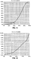
- Figures 9 and 10 show testing results using a control valve which may comprise the trim 10 or a variant thereof as constructed in accordance with the basic principles of present invention. Furthermore, Figures 11 and 12 show performance of such control valve exhibiting the following characteristics:
- control valve is capable of limiting the maximum velocity in the trim included therein and the clearance passages, thus preventing undesirable cavitation or plug erosion.
- the trim 10 disclosed above and shown in Figures 1-8 includes a pair of first fluid passageway columns 30 arranged in diametrically opposed relation to each other, and a pair of second fluid passageway columns 32 arranged in diametrically opposed relation to each other, for a total of four fluid passageway columns extending through the trim.
- the trim 10 could also have only a single first fluid passageway column 30 and a single second fluid passageway column 32 arranged in a prescribed orientation relative to each other.
- the trim includes a third fluid passageway column.
- the trim may only include three fluid passageway columns (i.e., one first fluid passageway column, one second fluid passageway column, and one third fluid passageway column) or six fluid passageway columns (i.e., two first fluid passageway columns, two second fluid passageway columns, and two third fluid passageway columns).
- Figures 13-15 show schematics of a trim having first, second, and third fluid passageway columns.
- the first fluid passageway column is depicted on the left and includes twenty stages
- the second fluid passageway column is depicted in the middle and includes twelve stages
- the third fluid passageway column is depicted on the right and includes four stages.
- Figures 13-15 show schematic representations of flow through the first, second, and third fluid passageway columns depending on the stroke of the stem.
- the trapezoidal shapes denote cavities in the stem
- the rectangular shapes denote cavities in the cage.
- a small stroke of the stem results in overlap between the stem and cage openings in the left column (i.e., the first fluid passageway), while the stem and cage openings in the middle and right columns are spaced from each other. Therefore, only the first fluid passageway column is open, resulting in fluid through the twenty stages of the first column.
- a medium stroke of the stem results in overlap between the stem and cage openings in the middle column (i.e., the second fluid passageway), while the stem and cage openings in the left and right columns are spaced from each other. Therefore, only the second fluid passageway column is open, resulting in fluid through the twelve stages of the second column.
- a large stroke of the stem results in overlap between the stem and cage openings in both the middle and right columns (i.e., the second and third fluid passageways), while the stem and cage openings in the left column are spaced from each other.
- the degree of overlap is greater in the right column and smaller in the middle column. Therefore, the majority of the fluid flow is through the third fluid passageway column, while a small portion of the fluid flow is simultaneously through the second fluid passageway column.
- the first fluid passageway column is closed, with no fluid flowing therethrough in response to a large stroke.
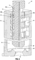
- FIGs 16-25 depict an exemplary version of a trim 110 and the components thereof, which embodies the structural and functional parameters of the trim schematically shown and described in Figures 13-15 .
- the trim 110 includes a cage 112 (see Figure 16 ), an outer sleeve 154 (see Figures 19-25 ), a stem 114 (see Figure 17 ) and a stem sleeve 168 (see Figure 18 ).
- the trim 110 is specifically configured and adapted to create at least three distinct fluid passageway columns, e.g., a first fluid passageway column 130, a second fluid passageway column 132, and a third fluid passageway column 133, having a separate number of "stages" associated therewith.
- the cage 112 has a generally cylindrical configuration and includes an inner surface 134 as well as an outer surface 136, with a central bore 138 extending axially through the cage 112 from a first end portion 140 to an opposing second end portion 142 thereof.
- the exemplary cage 112 includes a valve seat 128 disposed at the upper end portion 140 thereof, although those skilled in the art will readily understand that the cage 112 may be constructed such that the valve seat is at the lower end of the cage 112, similar to the configuration described above in relation to cage 12.
- the cage 112 includes a plurality of passageways formed therein, wherein the passageways define respective portions of the first, second, and third fluid passageway columns 130, 132, 133 (see Figures 19-20 ).
- the cage passageways used in forming the first fluid passageway column 130 will be referred to herein as the first cage passageways 144
- the cage passageways used in forming the second fluid passageway column 132 will be referred to herein as the second cage passageways 146
- the cage passageways used in forming the third fluid passageway column 133 will be referred to herein as the third cage passageways 147.
- the first cage passageways 144 are associated with the small slots 152 arranged in a linear array on the outer surface of the cage 112.
- the first cage passageways 144 extend into the cage 112 and define generally U-shaped channels having openings 148 (see Figure 21 ) in communication with the central bore 138.
- the first cage passageways 144 are preferably arranged in two diametrically opposed arrays.
- the second cage passageways 146 are associated with the medium-sized, generally quadrangular-shaped openings 156 arranged in a linear array on the outer surface of the cage 112.
- the second cage passageways 146 extend into the cage 112 and define generally U-shaped channels having openings 150 (see Figure 21 ) in communication with the central bore 138.
- the cage 112 preferably includes two sets of second passageway openings 150 arranged in diametrically opposed relation to each other.
- the third cage passageways 147 are associated with the large-sized openings 158 disposed on the outer surface of the cage 112 and positioned between the arrays of first and second cage passageways 144, 146.
- the third cage passageways 147 extend into the cage 112 and define generally U-shaped channels having openings 151 (see Figure 23 ) in communication with the central bore 138.
- the cage 112 preferably includes four sets of third passageway openings 151, arranged in two pairs of diametrically opposed sets.
- An outer cage sleeve 154 which may be disposed about the cage 112 for sealing the outer surface of the cage 112, thus defining individual flow passages within the cage 112. More specifically, the outer sleeve 154 preferably covers the openings 152, 156 and 158 to close off the first, second, and third cage passageways 144, 146, 147 at the outer surface of the cage 112. The outer sleeve 154 is preferably brazed or shrink fitted to the cage 112.
- Figure 17 shows a valve stem 114 configured for use with the cage 112.
- the valve stem 114 includes a beveled upper flange 126 which cooperates with the valve seat 128 to close the trim 110.
- the valve stem 114 further includes a plurality of stem passageways which are complimentary to the cage passageways 144, 146, 147 described above for use in forming the first, second, and third fluid passageway columns 130, 132, 133.
- the stem passageways used in forming the first fluid passageway column 130 will be referred to herein as the first stem passageways 160 (see Figure 19 )
- the stem passageways used in forming the second fluid passageway column 132 will be referred to herein as the second stem passageways 162 (see Figure 19 )
- the stem passageways in forming the third fluid passageway column 133 will be referred to herein as the third stem passageways 163 (see Figure 20 ).
- the first stem passageways 160 are associated with the smaller first stem openings 164 formed on the outer surface of the stem 114
- the second stem passageways 162 are associated with the medium-sized second stem openings 166 formed on the outer surface of the stem 114
- the third stem passageways 163 are associated with the large third stem openings 167 formed on the outer surface of the stem 114.
- Each stem passageway 160, 162, 163 is a generally U-shaped passageway having a pair of openings in communication with the outer surface of the stem 114.
- the preferred embodiment of the stem 114 includes diametrically opposed pairs of first and second stem passageways 160, 162, which are complimentary to the diametrically opposed pairs of first and second cage passageways 144, 146 formed in the cage 112. Furthermore, the stem 114 additionally preferably includes four third stem passageways 163 arranged in two pairs of diametrically opposed sets which are complimentary to the four third cage passageways 147 described above.
- Figure 18 is a perspective view of stem sleeve 168 which is disposed about the stem 114.
- the stem sleeve 168 is preferably assembled in one piece with the stem 114, and includes several openings which are in fluid communication with the stem passageways 160, 162, 163.
- the stem sleeve 168 includes a plurality of first sleeve openings 170, a plurality of second sleeve openings 172, and a plurality of third sleeve openings 174 which correspond to respective ones of the first stem passageways 160, the second stem passageways 162, and the third stem passageways 163.
- the first, second and third sleeve openings 170, 172, 174 may cooperate with the first, second and third stem openings 164, 166, 167 to collectively define the first, second and third stem passageways 160, 162, 163.
- the openings 170, 172, 174 formed in the stem sleeve 168 each have a generally triangular shape, although any shape is possible for achieving desired trim characteristics.
- the cage 112, cage sleeve 154, stem 114, and stem sleeve 168 are preferably fabricated through the use of a DMLS process as is described above, although other manufacturing techniques known in the art may also be used without departing from the scope of the present invention.
- the cage 112, cage sleeve 154, stem 114, and stem sleeve 168 are assembled in the manner depicted in Figures 19 and 20 .
- the stem 114 and stem sleeve 168 are axially moved to selectively open and close the first, second and third fluid passageway columns 130, 132, 133 to achieve desired trim parameters.
- the cross sectional view depicted in Figure 19 shows the first and second fluid passageway columns 130, 132, while Figure 20 shows the second and third fluid passageway columns 132, 133.
- the following discussion pertains to operation of an exemplary control valve including the cascade trim 110.
- the beveled upper flange 126 of the stem 114 is engaged with the upper valve seat 128 to close the valve inlet 116 and to prevent fluid from entering the first, second and third fluid passageway columns 130, 132, 133.
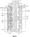
- Figure 21 shows the trim 110 of the control valve in a first open position.
- the valve stem 114 has been moved slightly from the closed position, with the beveled flange 126 of the stem 114 lifted from the valve seat 128 to allow for fluid passage through the valve inlet 116.
- the axial movement of the stem 114 causes a portion of the uppermost first stem passageway 160a to rise out of the cage 112, thereby exposing a portion of the uppermost first stem passageway 160a to fluid at the inlet 116.
- the first stem passageways 160 are brought into partial alignment with the first cage passageways 144 to create the first fluid passageway column 130 through the trim 110. As such, fluid may flow from the inlet to the outlet via the first fluid passageway column 130.
- Figure 21 additionally shows arrows representative of the fluid flow through that portion of the first passageway column 130 depicted in Figure 21 .
- the fluid flows through a very small opening created between the cage 112 and the stem 114, and into each uppermost first stem passageway 160a.
- the fluid flows through the uppermost first stem passageway 160a, which is a generally U-shaped passageway, and then into the corresponding uppermost first cage passageway 144a.
- the fluid must pass through a very small opening between the stem 114 and the cage 112 to flow therebetween.
- the fluid Once inside the uppermost first cage passageway 144a, the fluid flows through the generally U-shaped passage, and into the next, corresponding first stem passageway 160b.
- the fluid continues to flow through alternating first stem passageways 160 and first cage passageways 144 until the fluid enters the discharge chamber at the bottom of the cage 112.
- each “stage” is represented by a respective one of the first stem passageways 160 or the first cage passageways 144.
- the first "stage” includes the uppermost first stem passageway 160a
- the second “stage” includes the uppermost first cage passageway 144a
- the third “stage” includes the next first stem passageway 160b, and so forth.
- stem 114 and cage 112 include a diametrically opposed pair of the first fluid passageway columns 130 which each include eighteen stages
- contemplated variants of the cascade trim 110 may include fewer than eighteen stages or more than eighteen stages and/or greater or fewer than two first fluid passageway columns 130 without departing from the scope of the present invention.
- the second stem and cage passageways 162, 146 remain out of alignment with each other, and the uppermost second stem passageway 162a remains within the cage 112 to prevent fluid from entering the uppermost second stem passageway 162a.
- the second fluid passageway column 132 remains closed when the stem 114 is in the first position.
- the third stem and cage passageways 163, 147 also remain out of alignment with each other, and the uppermost third stem passageway 163a remains within the cage 112 to prevent fluid from entering the uppermost third stem passageway 163a.
- the third fluid passageway column 133 remains closed when the stem 114 is in the first position.
- valve stem 114 is shown in a second position, which results in fluid simultaneously flowing through both the first and second fluid passageway columns 130, 132, while the third fluid passageway column 133 remains closed, as described below.
- the beveled flange 126 of the stem 114 is spaced farther from the valve seat 128 relative to the spacing between the beveled flange 126 and the valve seat 128 when the stem 114 is in the first position.
- the first stem passageways 160 are further aligned with the first cage passageways 144. In this regard, as fluid flows between the stem 114 and the cage 112, the pressure drop achieved by passage therethrough is less than when the stem 114 is in the first position.
- first stem and cage passageways 160, 144 when the stem 114 is in the first position, only a small portion of the first stem and cage passageways 160, 144 are aligned with each other, which results in fluid to passing through a very small opening as the fluid flows between the stem 114 and the cage 112.
- stem 114 when the stem 114 is in the second position, a larger portion of the first stem and cage passageways 160, 144 are brought into alignment with each other, and thus, the opening through which the fluid travels between the stem 114 and cage 112 is larger, resulting in a smaller pressure drop.
- each “stage” is represented by a respective one of the second stem passageways 162 or the second cage passageways 146.
- the first "stage” includes the uppermost first stem passageway 162a
- the second “stage” includes the uppermost first cage passageway 146a
- the third “stage” includes the next first stem passageway 162b, and so forth.
- stem 114 and cage 112 include a diametrically opposed pair of the second passageway columns 132 which each include eight stages
- contemplated variants of the cascade trim 110 may include fewer than eight stages or more than eight stages and/or greater or fewer than two second fluid passageway columns 132 without departing from the scope of the present invention.
- the third stem and cage passageways 163, 147 also remain out of alignment with each other, and the uppermost third stem passageway 163a remains within the cage 112 to prevent fluid from entering the uppermost third stem passageway 163a.
- the third fluid passageway column 133 remains closed when the stem 114 is in the first position.
- the stem 114 is shown in the third position.
- both the first and third fluid passageway columns 130, 133 are closed, while the second fluid passageway column 132 is open.
- at least a portion of the second stem passageways 162 are aligned with the second cage passageways 146 to allow for fluid flow therebetween.
- the uppermost third stem passageway 163a remains within the cage 112 when the stem 114 is in the third position, thereby preventing fluid from entering the third fluid passageway column 133.
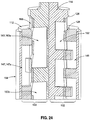
- the stem 114 is shown in a fourth position, wherein the second and third fluid passageway columns 132, 133 are open.
- the uppermost third stem passageway 163a is at least partially removed from the cage 112 to allow fluid to enter the uppermost third stem passageway 163a. Fluid flows through the uppermost third stem passageway 163a, and then into the uppermost third cage passageway 147a. The fluid continues into a subsequent third stem passageway 163, and then finally into a discharge chamber of the cage 112.
- each “stage” is represented by a respective one of the third stem passageways 163 or the third cage passageways 147.
- the first "stage” includes the uppermost first stem passageway 163a
- the second “stage” includes the uppermost third cage passageway 147a
- the third “stage” includes the next third stem passageway 163b, and so forth.
- stem 114 and cage 112 include two diametrically opposed pairs of the third fluid passageway columns 133 which each include four stages
- contemplated variants of the cascade trim 110 may include fewer than four stages or more than four stages and/or greater or fewer than a total of four third fluid passageway columns 132 without departing from the scope of the present invention.
- the second stem and cage passageways 162, 146 are brought into substantially complete alignment with each other to allow fluid to flow through the second fluid passageway column 132.
- the stem 114 when the stem 114 is in the fourth position, the first fluid passageway column 130 is closed. More specifically, the first stem passageways 160 are moved out of alignment with the first cage passageways 144 to prevent fluid flow through the first fluid passageway column 130.
- the stem 114 and cage 112 may additionally be configured such that when the stem 114 is in the fourth position, the first fluid passageway column 130 may be open simultaneously with the second and third fluid passageway columns 132, 133.
- Figure 25 shows the stem 114 in a fifth position, wherein the third fluid passageway column 133 is open, and the first and second fluid passageway columns 130, 132 are closed.
- the third stem and cage passageways 163, 147 are brought into substantially complete alignment with each other to place the third fluid passageway column 133 in a completely open configuration.
- the second stem and cage passageways 162, 146 are moved out of alignment with each other to close the second fluid passageway column 132.
- the first stem and cage passageways 160, 144 are also brought out of alignment with each other to close the first fluid passageway column 130.
- Figures 26 and 27 show testing results using a control valve which may comprise the trim 110 or a variant thereof as constructed in accordance with the basic principles of present invention, such control valve exhibiting the following characteristics:
Landscapes
- Engineering & Computer Science (AREA)
- General Engineering & Computer Science (AREA)
- Mechanical Engineering (AREA)
- Sliding Valves (AREA)
- Details Of Valves (AREA)
Claims (8)
- Garniture en cascade (10, 110) pour une soupape de commande de fluide, la garniture en cascade (10, 110) comprenant :une cage de soupape (12, 112) définissant une entrée de soupape (16) et une sortie de soupape (22); etune tige de soupape (14, 114) réciproquement mobile à l'intérieur de la cage de soupape (12, 112), la cage de soupape (12, 112) et la tige de soupape (14, 114) étant chacune configurée pour collectivement définir une première colonne de passage de fluide (30, 130) et une seconde colonne de passage de fluide (32, 132), chacune des première et seconde colonnes de passage de fluide (30, 32, 130, 132) s'étendant entre l'entrée de soupape (16) et la sortie de soupape (22) ;dans laquelle le mouvement réciproque de la tige de soupape (14, 114) par rapport à la cage de soupape (12, 112) provoque la constitution et la division sélectives de la première colonne de passage de fluide (30, 130) et de la seconde colonne de passage de fluide (32, 132) ; dans laquelle la première colonne de passage de fluide (30, 130) est formée pour présenter des caractéristiques de flux qui diffèrent de la seconde colonne de passage de fluide (32, 132) ; caractérisée en ce quechacune des première et seconde colonne 8 de passage de fluide (30, 32, 130, 132) s'étend au moins partiellement à travers la cage de soupape (12, 112) et la tige de soupape (14, 114);la tige de soupape (14, 114) étant mobile entre:une position fermée par rapport à la cage de soupape (12, 112), dans laquelle la première et la seconde colonne de passage de fluide (30, 32, 130, 132) sont fermées pour empêcher le fluide de circuler entre l'entrée de soupape (16) et la sortie de soupape (22) à travers les première et seconde colonnes de passage de fluide (30, 32, 130, 132) ;une première position de passage dans laquelle la première colonne de passage de fluide (30, 130) est ouverte et la seconde colonne de passage de fluide (32, 132) est fermée pour permettre au fluide de circuler entre l'entrée de soupape (16) et la sortie de soupape (22) à travers la première colonne de passage de fluide (30, 130) ; etune seconde position de passage dans laquelle la seconde colonne de passage de fluide (32, 132) est ouverte et la première colonne de passage de fluide (30, 130) est fermée pour permettre au fluide de circuler entre l'entrée de soupape (16) et la sortie de soupape (22) à travers la seconde colonne de passage de fluide (32, 132).
- Garniture en cascade (10, 110) selon la revendication 1, dans laquelle la tige de soupape (14, 114) est en outre mobile vers une position ouverte dans laquelle la première colonne de passage de fluide (30, 130) est ouverte et la seconde colonne de passage de fluide (32, 132) est ouverte pour permettre au fluide de circuler entre l'entrée de soupape (16) et la sortie de soupape (22) à travers les première et seconde colonnes de passage de fluide (30, 32, 130, 132).
- Garniture en cascade (10, 110) selon la revendication 1, dans laquelle la cage de soupape (12, 112) comprend une pluralité de premiers passages de cage formant une partie de la première colonne de passage de fluide (30, 130) et une pluralité de seconds passages de cage formant une partie de la seconde colonne de passage de fluide (32, 132).
- Garniture en cascade (10, 110) selon la revendication 3, dans laquelle la pluralité de premiers passages de cage sont espacés de la pluralité de seconds passages de cage.
- Garniture en cascade (10, 110) selon la revendication 3, dans laquelle :la tige de soupape (14, 114) comprend une pluralité de premiers passages de tige formant une partie de la première colonne de passage de fluide (30, 130) et une pluralité de seconds passages de tige formant une partie de la seconde colonne de passage de fluide (32, 132) ;les premiers passages de cage sont alignés avec les premiers passages de tige quand la première colonne de passage de fluide (30, 130) est ouverte ; etles seconds passages de cage sont alignés avec les seconds passages de tige quand la seconde colonne de passage de fluide (32, 132) est ouverte ;de préférencedans laquelle la pluralité de premiers passages de tige sont espacés de la pluralité de seconds passages de tige ; oudans laquelle chacun de la pluralité de seconds passages de tige comprend une portion axiale et une portion arquée.
- Garniture en cascade (10, 110) selon la revendication 1, comprenant en outre une manche agencée autour de la tige de soupape (14, 114) entre la tige de soupape (14, 114) et la cage de soupape (12, 112), la manche coopérant avec la tige de soupape (14, 114) et la cage de soupape (12, 112) pour définir la première colonne de passage de fluide (30, 130) et la seconde colonne de passage de fluide (32, 132).
- Garniture en cascade (10, 110) selon la revendication 1, dans laquelle :la première colonne de passage de fluide (30, 130) est configurée de façon à ce que le fluide circule à travers celle-ci à partir de l'entrée de soupape (16) vers la sortie de soupape (22), le fluide produit un premier nombre de transitions entre la tige de soupape (14, 114) et la cage de soupape (12, 112) ; etla seconde colonne de passage de fluide (32, 132) est configurée de façon à ce que le fluide circule à travers celle-ci à partir de l'entrée de soupape (16) vers la sortie de soupape (22), le fluide produit un second nombre de transitions entre la tige de soupape (14, 114) et la cage de soupape (12, 112) ;le premier nombre de transitions étant différent du second nombre de transitions.
- Garniture en cascade (10, 110) selon la revendication 1, dans laquelle la cage de soupape (12, 112) et la tige de soupape (14, 114) sont toutes les deux formées à travers frittage laser direct de métal.
Applications Claiming Priority (3)
| Application Number | Priority Date | Filing Date | Title |
|---|---|---|---|
| US201361856502P | 2013-07-19 | 2013-07-19 | |
| US14/333,313 US9556970B2 (en) | 2013-07-19 | 2014-07-16 | Cascade trim for control valve |
| PCT/US2014/047469 WO2015010132A1 (fr) | 2013-07-19 | 2014-07-21 | Garniture en cascade pour soupape de commande |
Publications (3)
| Publication Number | Publication Date |
|---|---|
| EP3022474A1 EP3022474A1 (fr) | 2016-05-25 |
| EP3022474A4 EP3022474A4 (fr) | 2017-03-15 |
| EP3022474B1 true EP3022474B1 (fr) | 2018-11-21 |
Family
ID=52342595
Family Applications (1)
| Application Number | Title | Priority Date | Filing Date |
|---|---|---|---|
| EP14825983.1A Active EP3022474B1 (fr) | 2013-07-19 | 2014-07-21 | Garniture en cascade pour soupape de commande |
Country Status (3)
| Country | Link |
|---|---|
| US (1) | US9556970B2 (fr) |
| EP (1) | EP3022474B1 (fr) |
| WO (1) | WO2015010132A1 (fr) |
Cited By (1)
| Publication number | Priority date | Publication date | Assignee | Title |
|---|---|---|---|---|
| US11566714B2 (en) | 2020-01-15 | 2023-01-31 | Flowserve Management Company | Fluid flow control devices and related systems and methods |
Families Citing this family (8)
| Publication number | Priority date | Publication date | Assignee | Title |
|---|---|---|---|---|
| US10094489B2 (en) | 2015-02-03 | 2018-10-09 | Control Components, Inc. | Axial resistance valve trim design |
| EP3396219B1 (fr) | 2017-04-28 | 2022-12-14 | Ratier-Figeac SAS | Soupapes |
| US10371265B2 (en) * | 2017-11-01 | 2019-08-06 | Fisher Controls International Llc | Process control valve and plug |
| US10781927B2 (en) * | 2018-07-12 | 2020-09-22 | Fisher Controls International Llc | Monolithic, non-plugging multi-stage valve trim |
| US11703146B2 (en) | 2018-08-03 | 2023-07-18 | Emerson Process Management (Tianjin) Valves Co., Ltd. | Control valves and cages that are adapted to reduce flashing and cavitation |
| US12422057B2 (en) | 2018-08-03 | 2025-09-23 | Emerson Process Management (Tianjin) Valve Co., Ltd. | Control valves and cages that are adapted to reduce flashing and cavitation |
| CN111473155B (zh) * | 2020-03-13 | 2022-04-08 | 合肥通用机械研究院有限公司 | 香槟塔型多级节流控制阀 |
| US11441686B2 (en) | 2021-02-04 | 2022-09-13 | Control Components, Inc. | Fluid flow control device with valve seat configured to mitigate flashing |
Family Cites Families (51)
| Publication number | Priority date | Publication date | Assignee | Title |
|---|---|---|---|---|
| US352273A (en) | 1886-11-09 | Eenaldo solano | ||
| US1645601A (en) * | 1926-10-26 | 1927-10-18 | Henry B Lee | Velocity-reducing valve |
| US1808808A (en) | 1928-10-15 | 1931-06-09 | Aeolian Co | Music roll magazine |
| US2764181A (en) * | 1952-11-15 | 1956-09-25 | Lockheed Aircraft Corp | Valve packing installation |
| US3078877A (en) | 1960-07-19 | 1963-02-26 | United Nuclear Corp | Labyrinth control valve |
| DE1147450B (de) * | 1962-03-23 | 1963-04-18 | Arap Armaturen Und App Ges Mit | Mehrstufiges Drosselventil mit einer Drosselkanaele aufweisenden Ventilspindel |
| DE1550435A1 (de) * | 1966-02-25 | 1970-08-13 | Wilhelm Odendahl | Drosselvorrichtung |
| US3485474A (en) * | 1966-08-03 | 1969-12-23 | Sheldon C Evans | Adjustable fluid restrictor |
| US3637188A (en) * | 1970-01-13 | 1972-01-25 | Baldwin Lima Hamilton Corp | Multistage throttle valve |
| FR2134072B2 (fr) * | 1970-07-06 | 1974-03-01 | Evans Sheldon | |
| US3715098A (en) * | 1971-07-06 | 1973-02-06 | H Baumann | Adjustable fluid restrictor method and apparatus |
| US3791413A (en) * | 1972-03-23 | 1974-02-12 | Leslie Co | Pressure reducing valve spool |
| US3920044A (en) * | 1972-07-11 | 1975-11-18 | Samson Apparatebau Ag | Device for obtaining quiet operation of valves, more particularly pressure reducing valves |
| US3971411A (en) | 1974-03-07 | 1976-07-27 | Masoneilan International, Inc. | Variable resistance type throttling trim |
| US3908698A (en) * | 1974-03-07 | 1975-09-30 | Hans D Baumann | Variable resistance type throttling trim |
| US4044992A (en) * | 1976-01-09 | 1977-08-30 | Consolidated Controls Corporation | High energy loss fluid flow control device |
| US4363464A (en) * | 1980-07-03 | 1982-12-14 | Spils Richard W | Angle globe valve |
| US4504040A (en) * | 1980-07-03 | 1985-03-12 | Spils Richard W | Multiple stage valve |
| US4479509A (en) * | 1981-08-03 | 1984-10-30 | E. I. Du Pont De Nemours And Company | Fluid control apparatus |
| DE3241751C2 (de) * | 1982-11-11 | 1985-10-03 | Danfoss A/S, Nordborg | Prioritätsventil für hydraulische Anlagen |
| US4632359A (en) * | 1983-06-06 | 1986-12-30 | International Combustion Australia Limited | Low noise flow control valve |
| USRE33053E (en) * | 1984-05-07 | 1989-09-12 | Cameron Iron Works Usa Inc. | Low noise valve |
| US4549718A (en) * | 1984-05-07 | 1985-10-29 | Smith International, Inc. | Low noise valve |
| US4634095A (en) * | 1985-07-26 | 1987-01-06 | Taylor Julian S | Multiple stage choke valve |
| US5018703A (en) * | 1988-01-14 | 1991-05-28 | Teledyne Industries, Inc. | Valve design to reduce cavitation and noise |
| US4967783A (en) * | 1990-02-22 | 1990-11-06 | Keystone International Holdings Corp. | Recirculation valve with pilot valve |
| US5113908A (en) * | 1990-09-04 | 1992-05-19 | Dresser Industries, Inc. | Multistep trim design |
| JPH0783335A (ja) * | 1993-09-14 | 1995-03-28 | Mitsubishi Heavy Ind Ltd | 流量制御弁 |
| US5803119A (en) | 1995-02-08 | 1998-09-08 | Control Components Inc. | Fluid flow control device |
| US5615708A (en) * | 1995-10-23 | 1997-04-01 | Fisher Controls International, Inc. | Flow control valve with non-plugging multi-stage valve trim |
| US5765814A (en) | 1995-11-15 | 1998-06-16 | Fisher Controls International, Inc. | Flow rate stabilizer for throttling valves |
| JP3441289B2 (ja) * | 1996-04-02 | 2003-08-25 | 日本電産トーソク株式会社 | 油圧回路用弁構造 |
| FR2773865B1 (fr) * | 1998-01-21 | 2000-03-24 | Theobald A | Vanne de reglage de debit |
| US6047735A (en) * | 1998-02-14 | 2000-04-11 | Casey; Gary L. | High speed solenoid valve |
| US6382233B1 (en) * | 1999-06-18 | 2002-05-07 | Yandle, Ii S. Elwood | Plastic hydraulic hammer reduction system |
| US6926032B2 (en) * | 2002-09-13 | 2005-08-09 | Saudi Arabian Oil Company | Pressure-reducing control valve for severe service conditions |
| US7055548B2 (en) * | 2003-05-30 | 2006-06-06 | Fisher Controls International Llc | Control valve trim and seat design for valve trim with minimal unbalanced area |
| US7363941B2 (en) * | 2004-12-16 | 2008-04-29 | Dresser, Inc. | Fluid control valve device |
| US7690400B2 (en) * | 2005-02-28 | 2010-04-06 | Flowserve Management Company | Noise reducing fluid passageways for fluid control devices |
| US20070040136A1 (en) * | 2005-08-22 | 2007-02-22 | Caprera Brian J | Fluid control valve device |
| US7455115B2 (en) * | 2006-01-23 | 2008-11-25 | Schlumberger Technology Corporation | Flow control device |
| DE102007040997B4 (de) * | 2007-08-29 | 2015-01-08 | Weatherford Energy Services Gmbh | Regelbares Druckminderventil und Verwendung desselben zur Erzeugung von Druckänderungssignalen |
| WO2009070512A1 (fr) | 2007-11-26 | 2009-06-04 | Cameron International Corporation | Organes internes de vanne de régulation |
| US8826938B2 (en) | 2008-01-22 | 2014-09-09 | Control Components, Inc. | Direct metal laser sintered flow control element |
| US8393355B2 (en) * | 2009-05-28 | 2013-03-12 | Control Components, Inc. | Short stroke control valve |
| US8464756B2 (en) * | 2009-09-22 | 2013-06-18 | Eaton Corporation | Spool valve |
| US8998169B2 (en) * | 2011-02-28 | 2015-04-07 | Control Components, Inc. | Toothed gate valve seat |
| JP5602073B2 (ja) * | 2011-03-16 | 2014-10-08 | カヤバ工業株式会社 | 制御弁 |
| JP5602074B2 (ja) * | 2011-03-16 | 2014-10-08 | カヤバ工業株式会社 | 制御弁 |
| CN202790586U (zh) * | 2011-12-30 | 2013-03-13 | 艾默生过程管理(天津)阀门有限公司 | 用于流动控制阀的阀内件组件和流动控制阀 |
| US9022071B2 (en) * | 2012-04-24 | 2015-05-05 | Control Components, Inc. | Multi-stage fluid flow control device |
-
2014
- 2014-07-16 US US14/333,313 patent/US9556970B2/en active Active
- 2014-07-21 WO PCT/US2014/047469 patent/WO2015010132A1/fr not_active Ceased
- 2014-07-21 EP EP14825983.1A patent/EP3022474B1/fr active Active
Non-Patent Citations (1)
| Title |
|---|
| None * |
Cited By (2)
| Publication number | Priority date | Publication date | Assignee | Title |
|---|---|---|---|---|
| US11566714B2 (en) | 2020-01-15 | 2023-01-31 | Flowserve Management Company | Fluid flow control devices and related systems and methods |
| US12123519B2 (en) | 2020-01-15 | 2024-10-22 | Flowserve Pte. Ltd. | Fluid flow control devices and related systems and methods |
Also Published As
| Publication number | Publication date |
|---|---|
| US20150020903A1 (en) | 2015-01-22 |
| US9556970B2 (en) | 2017-01-31 |
| WO2015010132A1 (fr) | 2015-01-22 |
| EP3022474A4 (fr) | 2017-03-15 |
| EP3022474A1 (fr) | 2016-05-25 |
Similar Documents
| Publication | Publication Date | Title |
|---|---|---|
| EP3022474B1 (fr) | Garniture en cascade pour soupape de commande | |
| EP2841833B1 (fr) | Dispositif de régulation d'écoulement de fluide à étages multiples | |
| US3529628A (en) | Variable fluid restrictor | |
| CN208185485U (zh) | 流体阀和用于流体控制阀的内件组件 | |
| US4617963A (en) | Control valve with anticavitation trim | |
| EP1266166B1 (fr) | Dispositif servant a limiter l'energie d'un liquide | |
| EP3612758B1 (fr) | Soupape de commande avec cage de soupape haute performance | |
| US10094489B2 (en) | Axial resistance valve trim design | |
| CN108700210B (zh) | 混合阀芯 | |
| CN105593586B (zh) | 用于调节流体流动的控制阀 | |
| US10655738B2 (en) | Multistage stacked disc choke | |
| CN107588204A (zh) | 级联可控流体控制阀以及用于流体控制阀的阀内件 | |
| CN209483957U (zh) | 控制阀以及用于控制阀的笼 | |
| CN206830935U (zh) | 具有多级降压阀芯的降压阀 | |
| US12123519B2 (en) | Fluid flow control devices and related systems and methods | |
| DE102007035431B4 (de) | Regelventil insbesondere für Fluide mit Abströmmöglichkeit für große Massenströme | |
| JPH052878B2 (fr) | ||
| CN214661168U (zh) | 止回阀及具备该止回阀的止回阀装置 | |
| JP2005090555A (ja) | 減圧調節弁 |
Legal Events
| Date | Code | Title | Description |
|---|---|---|---|
| PUAI | Public reference made under article 153(3) epc to a published international application that has entered the european phase |
Free format text: ORIGINAL CODE: 0009012 |
|
| 17P | Request for examination filed |
Effective date: 20160218 |
|
| AK | Designated contracting states |
Kind code of ref document: A1 Designated state(s): AL AT BE BG CH CY CZ DE DK EE ES FI FR GB GR HR HU IE IS IT LI LT LU LV MC MK MT NL NO PL PT RO RS SE SI SK SM TR |
|
| AX | Request for extension of the european patent |
Extension state: BA ME |
|
| DAX | Request for extension of the european patent (deleted) | ||
| A4 | Supplementary search report drawn up and despatched |
Effective date: 20170210 |
|
| RIC1 | Information provided on ipc code assigned before grant |
Ipc: F16K 47/08 20060101ALI20170206BHEP Ipc: F16K 47/04 20060101ALI20170206BHEP Ipc: F16K 1/54 20060101ALI20170206BHEP Ipc: F16K 47/06 20060101AFI20170206BHEP Ipc: F16K 47/12 20060101ALI20170206BHEP |
|
| STAA | Information on the status of an ep patent application or granted ep patent |
Free format text: STATUS: EXAMINATION IS IN PROGRESS |
|
| 17Q | First examination report despatched |
Effective date: 20180126 |
|
| GRAP | Despatch of communication of intention to grant a patent |
Free format text: ORIGINAL CODE: EPIDOSNIGR1 |
|
| STAA | Information on the status of an ep patent application or granted ep patent |
Free format text: STATUS: GRANT OF PATENT IS INTENDED |
|
| INTG | Intention to grant announced |
Effective date: 20180820 |
|
| GRAS | Grant fee paid |
Free format text: ORIGINAL CODE: EPIDOSNIGR3 |
|
| GRAA | (expected) grant |
Free format text: ORIGINAL CODE: 0009210 |
|
| STAA | Information on the status of an ep patent application or granted ep patent |
Free format text: STATUS: THE PATENT HAS BEEN GRANTED |
|
| AK | Designated contracting states |
Kind code of ref document: B1 Designated state(s): AL AT BE BG CH CY CZ DE DK EE ES FI FR GB GR HR HU IE IS IT LI LT LU LV MC MK MT NL NO PL PT RO RS SE SI SK SM TR |
|
| REG | Reference to a national code |
Ref country code: CH Ref legal event code: EP |
|
| REG | Reference to a national code |
Ref country code: IE Ref legal event code: FG4D |
|
| REG | Reference to a national code |
Ref country code: DE Ref legal event code: R096 Ref document number: 602014036628 Country of ref document: DE |
|
| REG | Reference to a national code |
Ref country code: AT Ref legal event code: REF Ref document number: 1067936 Country of ref document: AT Kind code of ref document: T Effective date: 20181215 |
|
| REG | Reference to a national code |
Ref country code: NL Ref legal event code: MP Effective date: 20181121 |
|
| REG | Reference to a national code |
Ref country code: AT Ref legal event code: MK05 Ref document number: 1067936 Country of ref document: AT Kind code of ref document: T Effective date: 20181121 |
|
| PG25 | Lapsed in a contracting state [announced via postgrant information from national office to epo] |
Ref country code: IS Free format text: LAPSE BECAUSE OF FAILURE TO SUBMIT A TRANSLATION OF THE DESCRIPTION OR TO PAY THE FEE WITHIN THE PRESCRIBED TIME-LIMIT Effective date: 20190321 Ref country code: FI Free format text: LAPSE BECAUSE OF FAILURE TO SUBMIT A TRANSLATION OF THE DESCRIPTION OR TO PAY THE FEE WITHIN THE PRESCRIBED TIME-LIMIT Effective date: 20181121 Ref country code: BG Free format text: LAPSE BECAUSE OF FAILURE TO SUBMIT A TRANSLATION OF THE DESCRIPTION OR TO PAY THE FEE WITHIN THE PRESCRIBED TIME-LIMIT Effective date: 20190221 Ref country code: HR Free format text: LAPSE BECAUSE OF FAILURE TO SUBMIT A TRANSLATION OF THE DESCRIPTION OR TO PAY THE FEE WITHIN THE PRESCRIBED TIME-LIMIT Effective date: 20181121 Ref country code: LV Free format text: LAPSE BECAUSE OF FAILURE TO SUBMIT A TRANSLATION OF THE DESCRIPTION OR TO PAY THE FEE WITHIN THE PRESCRIBED TIME-LIMIT Effective date: 20181121 Ref country code: ES Free format text: LAPSE BECAUSE OF FAILURE TO SUBMIT A TRANSLATION OF THE DESCRIPTION OR TO PAY THE FEE WITHIN THE PRESCRIBED TIME-LIMIT Effective date: 20181121 Ref country code: AT Free format text: LAPSE BECAUSE OF FAILURE TO SUBMIT A TRANSLATION OF THE DESCRIPTION OR TO PAY THE FEE WITHIN THE PRESCRIBED TIME-LIMIT Effective date: 20181121 Ref country code: LT Free format text: LAPSE BECAUSE OF FAILURE TO SUBMIT A TRANSLATION OF THE DESCRIPTION OR TO PAY THE FEE WITHIN THE PRESCRIBED TIME-LIMIT Effective date: 20181121 Ref country code: NO Free format text: LAPSE BECAUSE OF FAILURE TO SUBMIT A TRANSLATION OF THE DESCRIPTION OR TO PAY THE FEE WITHIN THE PRESCRIBED TIME-LIMIT Effective date: 20190221 |
|
| PG25 | Lapsed in a contracting state [announced via postgrant information from national office to epo] |
Ref country code: NL Free format text: LAPSE BECAUSE OF FAILURE TO SUBMIT A TRANSLATION OF THE DESCRIPTION OR TO PAY THE FEE WITHIN THE PRESCRIBED TIME-LIMIT Effective date: 20181121 Ref country code: PT Free format text: LAPSE BECAUSE OF FAILURE TO SUBMIT A TRANSLATION OF THE DESCRIPTION OR TO PAY THE FEE WITHIN THE PRESCRIBED TIME-LIMIT Effective date: 20190321 Ref country code: RS Free format text: LAPSE BECAUSE OF FAILURE TO SUBMIT A TRANSLATION OF THE DESCRIPTION OR TO PAY THE FEE WITHIN THE PRESCRIBED TIME-LIMIT Effective date: 20181121 Ref country code: GR Free format text: LAPSE BECAUSE OF FAILURE TO SUBMIT A TRANSLATION OF THE DESCRIPTION OR TO PAY THE FEE WITHIN THE PRESCRIBED TIME-LIMIT Effective date: 20190222 Ref country code: SE Free format text: LAPSE BECAUSE OF FAILURE TO SUBMIT A TRANSLATION OF THE DESCRIPTION OR TO PAY THE FEE WITHIN THE PRESCRIBED TIME-LIMIT Effective date: 20181121 Ref country code: AL Free format text: LAPSE BECAUSE OF FAILURE TO SUBMIT A TRANSLATION OF THE DESCRIPTION OR TO PAY THE FEE WITHIN THE PRESCRIBED TIME-LIMIT Effective date: 20181121 |
|
| PG25 | Lapsed in a contracting state [announced via postgrant information from national office to epo] |
Ref country code: IT Free format text: LAPSE BECAUSE OF FAILURE TO SUBMIT A TRANSLATION OF THE DESCRIPTION OR TO PAY THE FEE WITHIN THE PRESCRIBED TIME-LIMIT Effective date: 20181121 Ref country code: PL Free format text: LAPSE BECAUSE OF FAILURE TO SUBMIT A TRANSLATION OF THE DESCRIPTION OR TO PAY THE FEE WITHIN THE PRESCRIBED TIME-LIMIT Effective date: 20181121 Ref country code: CZ Free format text: LAPSE BECAUSE OF FAILURE TO SUBMIT A TRANSLATION OF THE DESCRIPTION OR TO PAY THE FEE WITHIN THE PRESCRIBED TIME-LIMIT Effective date: 20181121 Ref country code: DK Free format text: LAPSE BECAUSE OF FAILURE TO SUBMIT A TRANSLATION OF THE DESCRIPTION OR TO PAY THE FEE WITHIN THE PRESCRIBED TIME-LIMIT Effective date: 20181121 |
|
| REG | Reference to a national code |
Ref country code: DE Ref legal event code: R097 Ref document number: 602014036628 Country of ref document: DE |
|
| PG25 | Lapsed in a contracting state [announced via postgrant information from national office to epo] |
Ref country code: EE Free format text: LAPSE BECAUSE OF FAILURE TO SUBMIT A TRANSLATION OF THE DESCRIPTION OR TO PAY THE FEE WITHIN THE PRESCRIBED TIME-LIMIT Effective date: 20181121 Ref country code: SM Free format text: LAPSE BECAUSE OF FAILURE TO SUBMIT A TRANSLATION OF THE DESCRIPTION OR TO PAY THE FEE WITHIN THE PRESCRIBED TIME-LIMIT Effective date: 20181121 Ref country code: RO Free format text: LAPSE BECAUSE OF FAILURE TO SUBMIT A TRANSLATION OF THE DESCRIPTION OR TO PAY THE FEE WITHIN THE PRESCRIBED TIME-LIMIT Effective date: 20181121 Ref country code: SK Free format text: LAPSE BECAUSE OF FAILURE TO SUBMIT A TRANSLATION OF THE DESCRIPTION OR TO PAY THE FEE WITHIN THE PRESCRIBED TIME-LIMIT Effective date: 20181121 |
|
| PLBE | No opposition filed within time limit |
Free format text: ORIGINAL CODE: 0009261 |
|
| STAA | Information on the status of an ep patent application or granted ep patent |
Free format text: STATUS: NO OPPOSITION FILED WITHIN TIME LIMIT |
|
| 26N | No opposition filed |
Effective date: 20190822 |
|
| PG25 | Lapsed in a contracting state [announced via postgrant information from national office to epo] |
Ref country code: SI Free format text: LAPSE BECAUSE OF FAILURE TO SUBMIT A TRANSLATION OF THE DESCRIPTION OR TO PAY THE FEE WITHIN THE PRESCRIBED TIME-LIMIT Effective date: 20181121 |
|
| REG | Reference to a national code |
Ref country code: DE Ref legal event code: R119 Ref document number: 602014036628 Country of ref document: DE |
|
| PG25 | Lapsed in a contracting state [announced via postgrant information from national office to epo] |
Ref country code: MC Free format text: LAPSE BECAUSE OF FAILURE TO SUBMIT A TRANSLATION OF THE DESCRIPTION OR TO PAY THE FEE WITHIN THE PRESCRIBED TIME-LIMIT Effective date: 20181121 |
|
| REG | Reference to a national code |
Ref country code: CH Ref legal event code: PL |
|
| PG25 | Lapsed in a contracting state [announced via postgrant information from national office to epo] |
Ref country code: TR Free format text: LAPSE BECAUSE OF FAILURE TO SUBMIT A TRANSLATION OF THE DESCRIPTION OR TO PAY THE FEE WITHIN THE PRESCRIBED TIME-LIMIT Effective date: 20181121 |
|
| REG | Reference to a national code |
Ref country code: BE Ref legal event code: MM Effective date: 20190731 |
|
| PG25 | Lapsed in a contracting state [announced via postgrant information from national office to epo] |
Ref country code: DE Free format text: LAPSE BECAUSE OF NON-PAYMENT OF DUE FEES Effective date: 20200201 |
|
| PG25 | Lapsed in a contracting state [announced via postgrant information from national office to epo] |
Ref country code: LU Free format text: LAPSE BECAUSE OF NON-PAYMENT OF DUE FEES Effective date: 20190721 Ref country code: CH Free format text: LAPSE BECAUSE OF NON-PAYMENT OF DUE FEES Effective date: 20190731 Ref country code: BE Free format text: LAPSE BECAUSE OF NON-PAYMENT OF DUE FEES Effective date: 20190731 Ref country code: LI Free format text: LAPSE BECAUSE OF NON-PAYMENT OF DUE FEES Effective date: 20190731 |
|
| PG25 | Lapsed in a contracting state [announced via postgrant information from national office to epo] |
Ref country code: FR Free format text: LAPSE BECAUSE OF NON-PAYMENT OF DUE FEES Effective date: 20190731 |
|
| PG25 | Lapsed in a contracting state [announced via postgrant information from national office to epo] |
Ref country code: IE Free format text: LAPSE BECAUSE OF NON-PAYMENT OF DUE FEES Effective date: 20190721 |
|
| PG25 | Lapsed in a contracting state [announced via postgrant information from national office to epo] |
Ref country code: CY Free format text: LAPSE BECAUSE OF FAILURE TO SUBMIT A TRANSLATION OF THE DESCRIPTION OR TO PAY THE FEE WITHIN THE PRESCRIBED TIME-LIMIT Effective date: 20181121 |
|
| PG25 | Lapsed in a contracting state [announced via postgrant information from national office to epo] |
Ref country code: MT Free format text: LAPSE BECAUSE OF FAILURE TO SUBMIT A TRANSLATION OF THE DESCRIPTION OR TO PAY THE FEE WITHIN THE PRESCRIBED TIME-LIMIT Effective date: 20181121 Ref country code: HU Free format text: LAPSE BECAUSE OF FAILURE TO SUBMIT A TRANSLATION OF THE DESCRIPTION OR TO PAY THE FEE WITHIN THE PRESCRIBED TIME-LIMIT; INVALID AB INITIO Effective date: 20140721 |
|
| PG25 | Lapsed in a contracting state [announced via postgrant information from national office to epo] |
Ref country code: MK Free format text: LAPSE BECAUSE OF FAILURE TO SUBMIT A TRANSLATION OF THE DESCRIPTION OR TO PAY THE FEE WITHIN THE PRESCRIBED TIME-LIMIT Effective date: 20181121 |
|
| P01 | Opt-out of the competence of the unified patent court (upc) registered |
Effective date: 20230530 |
|
| PGFP | Annual fee paid to national office [announced via postgrant information from national office to epo] |
Ref country code: GB Payment date: 20250722 Year of fee payment: 12 |