EP3023185A2 - Outil entraîné en rotation autour d'un axe de rotation ou d'oscillation comprenant un profil d'entraînement destiné a s'accoupler à un profil d'entraînement - Google Patents
Outil entraîné en rotation autour d'un axe de rotation ou d'oscillation comprenant un profil d'entraînement destiné a s'accoupler à un profil d'entraînement Download PDFInfo
- Publication number
- EP3023185A2 EP3023185A2 EP15195574.7A EP15195574A EP3023185A2 EP 3023185 A2 EP3023185 A2 EP 3023185A2 EP 15195574 A EP15195574 A EP 15195574A EP 3023185 A2 EP3023185 A2 EP 3023185A2
- Authority
- EP
- European Patent Office
- Prior art keywords
- window
- tool
- drive
- section
- frame
- Prior art date
- Legal status (The legal status is an assumption and is not a legal conclusion. Google has not performed a legal analysis and makes no representation as to the accuracy of the status listed.)
- Granted
Links
Images

Classifications
-
- B—PERFORMING OPERATIONS; TRANSPORTING
- B23—MACHINE TOOLS; METAL-WORKING NOT OTHERWISE PROVIDED FOR
- B23D—PLANING; SLOTTING; SHEARING; BROACHING; SAWING; FILING; SCRAPING; LIKE OPERATIONS FOR WORKING METAL BY REMOVING MATERIAL, NOT OTHERWISE PROVIDED FOR
- B23D61/00—Tools for sawing machines or sawing devices; Clamping devices for these tools
- B23D61/006—Oscillating saw blades
-
- B—PERFORMING OPERATIONS; TRANSPORTING
- B24—GRINDING; POLISHING
- B24B—MACHINES, DEVICES, OR PROCESSES FOR GRINDING OR POLISHING; DRESSING OR CONDITIONING OF ABRADING SURFACES; FEEDING OF GRINDING, POLISHING, OR LAPPING AGENTS
- B24B23/00—Portable grinding machines, e.g. hand-guided; Accessories therefor
- B24B23/04—Portable grinding machines, e.g. hand-guided; Accessories therefor with oscillating grinding tools; Accessories therefor
-
- B—PERFORMING OPERATIONS; TRANSPORTING
- B24—GRINDING; POLISHING
- B24B—MACHINES, DEVICES, OR PROCESSES FOR GRINDING OR POLISHING; DRESSING OR CONDITIONING OF ABRADING SURFACES; FEEDING OF GRINDING, POLISHING, OR LAPPING AGENTS
- B24B45/00—Means for securing grinding wheels on rotary arbors
- B24B45/006—Quick mount and release means for disc-like wheels, e.g. on power tools
Definitions
- the invention relates to a tool having a working section for machining a workpiece and a spaced therefrom, formed by an optionally curved flat piece drive section having a drive profile for coupling with a driven profile of a prime mover, with the tool oscillating in particular about an axis or rotating can be moved, wherein the drive portion has a closed-round window and in the region of the frame of the window form-fitting engagement openings for engagement of form-fitting engagement projections of the output profile.
- a generic tool is for example from the DE 20 2010 013 008 U1 . DE 20 2011 000 517 U1 . DE 20 2011 052 299 U1 or one DE 10 2004 050 798 A1 previously known.
- the tools described in the cited documents are formed by sheet metal parts which have two end sections. The two end sections are each formed by flat pieces. An end portion forms a working portion having a saw toothing, with which a workpiece can be machined. The spaced therefrom end portion of the tool forms a drive section with a window having a drive profile. The edge of the window or the frame surrounding the window has openings for the rotational coupling of the drive section to an output profile of a drive machine.
- the output profile of the drive machine is coupled to the drive profile of the tool in such a way that by a drive movement the prime mover the tool can be moved. It is in particular an oscillating or rotating movement of the drive axle.
- the window is surrounded by the window frame.
- the output profile is inserted into the window, so that the form-fitting engagement projections enter into the form-fitting engagement openings.
- a fastening nut which axially couples the drive section of the tool to the output profile of the drive machine, must be screwed onto a threaded section of the output profile.
- the invention is based on the object to continue to use a generic tool nutzsvorteilhaft on.
- the frame of the window should have predetermined separation points. These serve to break out a Ausbrechabiteses from the frame.
- These predetermined separation points can be formed by webs. These webs can form marginal edges. The marginal edges may form an edge portion of a form-fitting engagement opening. The marginal edges could also form the edge of incisions in the frame of the window.
- the cuts can be made from the window into the frame. The cuts can also be introduced from the outside into the frame. The breakpoints thus form material weaknesses where the window frame can be broken.
- the breakout portion may be formed by two or more sections. The sections are connected to each other at predetermined separation points.
- the flat piece, of which the window frame is formed is preferably made of metal, more preferably of a refracting in a bending metal, in particular a steel and more preferably of a hardened steel.
- a tool such as a pair of pliers can be used. With this pair of pliers, the window frame is subjected to bending in the region of the stripping section, so that a break occurs in the area of the predetermined separation points. After the breaking out of the breaking-out section, an opening remains which has a width.
- the over the circumferential direction of the window extending width of the opening is preferably greater than a minimum diameter of the window and in particular sufficiently large, so that a drive shaft of a prime mover can be inserted through the open towards the outside opening, so that the tool not only axially an output shaft of a prime mover but also in the radial direction on the output shaft of the prime mover can be plugged.
- the tool respectively the drive portion of the tool may have a centerline. This centerline is preferably an axis of symmetry that passes through a center of the window. The resulting from the breaking out of Ausbrechabitese opening can be aligned symmetrically with respect to the center line or axis of symmetry.
- the opening can also be aligned asymmetrically to this line, in particular the axis of symmetry, it can for example be offset laterally thereto.
- the opening formed by the breakout of the breakaway sections is preferably a radial opening.
- the opening can also connect a window-like recess, which is arranged in particular between the drive section and the output section, with the window of the drive profile.
- the window-like, preferably ring-shaped recess has a larger open space and in particular a larger minimum diameter than the window of the drive profile, so that through this recess, for example, provided with a mother output shaft of the drive machine can be inserted.
- the tool according to the invention consists essentially of two parts, both of which are formed by flat pieces.
- a first flat piece forms the working section. This preferably extends in a plane and is connected to an attachment point of the second flat piece, which forms the drive portion.
- the drive section is preferably formed by a curved flat piece. It may have two bending edges, so that it is bent in a Z-shaped cross-section. The bending lines run parallel to each other, so that the drive section receives a staircase shape.
- Another aspect of the invention is concerned with the compensation of an imbalance of a generic tool.
- the center of the drive section opposite the attachment point has a mass distribution relative to a center point of the window defined by the movement or rotation axis, that the center of gravity of the drive section is either in the center or relative to the attachment point beyond the center on the center line lies.
- the offset of the center of gravity in the direction away from the working portion of the tool is preferably achieved by means of a compensation mass.
- the compensation mass can be achieved by a widened portion of the attachment point opposite region of the sheet. This can have a rounded outline contour. If the attachment point is connected to a working section, the center of gravity may still be in an eccentric position.
- the Ausbrechabsacrificing has a side facing the window and mitaus stipulate the contour of the edge of the window and a side opposite, window facing away from the side, which mit indicate the outline contour of the drive section.
- Two further, opposite sides of the Ausbrechabiteses form attachment sides, with which the Ausbrechabites is separably attached to the drive section.
- the predetermined separation points are each formed by a web. The two webs lie on a Tangentialline relative to a circle around the center of the window or the drive axle.
- the predetermined breaking line passing through the two webs intersects a radial extending through the axis approximately in the middle between the two webs, so that the breaking-out section can be separated by attacking the jaws of a pair of pliers by multiple bending pivoting about the predetermined breaking line in a simple manner. This is done by a material fatigue in the area of the predetermined separation point, where the webs are bent when swinging back and forth.
- Each of the two attachment sides of the Ausbrechabiteses is preferably only connected to the drive portion with a single web, wherein the two webs define the predetermined breaking line, which is a bending line.
- the web forms a radially outwardly facing edge, which is formed by a radially outer cut in the frame of the window.
- the web also forms a radially inwardly facing edge, which is formed by a radially inner recess in the frame.
- the radially inner cut can here be formed by a form-fitting engagement opening, which is connected via a channel with the free surface of the window.
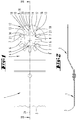
- the saw is a saw, which consists of two flat pieces.
- a flat piece forms a working section 1, which has a toothed edge at its end.
- This saw toothing 3 can run straight or along a curve.
- the center of the arc is located in a center of rotation or oscillation, around which the tool is driven to rotate or oscillate.
- the working section 1 is connected to a drive section 2 likewise formed by a flat piece.
- the drive section 2 is preferably made of a hardened steel. It is connected, for example via welds, rivets or the like to the working section 1 and has a height-offset to the connecting portion with the working section 1 portion having a drive profile 4.
- the drive profile 4 forms a window 11 having a circular outline contour line.
- the axis 5 of the window forms the oscillation or rotation center. From the circular arc defining a minimum diameter of the window go radially outwardly directed slots. There are in total four mutually offset by 90 ° from each other arranged form-fitting engagement openings 6, 9 are provided. Between the elongated form-fitting engagement openings 6, 9 are also open to the window 11 Form gleicheingriffsö réelleen 8, 8 'also encircled, from the circular minimum outline contour line of the window 11 radially outwardly spaced form-fitting openings 7,10 provided at a 30 ° distance to the Center 5 are arranged offset.
- the different form-fitting engagement openings 6 to 10 serve the engagement of mutually differently shaped output profiles of drive machines from different manufacturers.
- the window 11 is surrounded by a frame 12 rings.
- the frame has an inner edge which is structured by the form-fitting engagement openings 6, 8, 8 'and runs on the circular contour line delimiting the window 11.
- the window-like form-fitting engagement openings 7, 10 are arranged in the frame 12.
- the frame also has an outer edge, which is formed by the outer edge of the drive section 2 and in the exemplary embodiment partially extends on a semicircular line. The edge runs here on a portion of a circular arc around the center. 5
- the predetermined separation point 15 is a material weakening of the window frame 12.
- the predetermined separation point 15 extends along a center line 24, which passes through an axis 5 through the symmetry axis formed.
- the predetermined separation point 15 also extends on a passing through the center 5 line, ie on a radial. This radial is offset from the axis of symmetry 24 by 45 °.
- the frame 12 has notches 19, 20.
- the recess 19 extends in a V-shape from the outer edge of the window 12 radially inwardly.
- the incision 20 extends in a V-shape radially outward from the radially outer edge of a form-fitting engagement opening 9.
- the two V-tips are on the line of the Solltrennstelle 15, which is formed by the cuts 19, 20.
- the two mirror-symmetrical sections 16, 17 of the breaking-away section are respectively connected to predetermined separating points 13, 14 with fixed sections of the frame 12.
- the Ausbrechabites 16,17 thus forms a part of the frame 12, which extends over a peripheral portion of about 60 ° around the center 5.
- a predetermined separation point 13 is formed by a trapezoidal web.
- a radially outwardly facing edge of the web is formed by a radially outer cut 18 in the frame 12.
- a radially inwardly facing edge of the web forming the separating point 14 is formed by an edge of the form-fitting engagement opening 10. The breaking line of the predetermined separation point 13 runs along the short end of the web.
- a second predetermined separation point 14 is likewise formed by a web.
- the peripheral edge of the web forming the predetermined separation point 14 pointing radially outward is formed by an edge section of the form-fitting engagement opening 10.
- the form-fitting engagement opening 10 is both radially outward Direction towards the predetermined breaking point 14 and in the radial inward direction towards the web forming the predetermined separation point 14 widened.
- the radially inwardly facing edge of the predetermined separation point 14 forming web is formed by a notch 21 which increases the form-fitting engagement opening 8 in the radial outward direction.
- the material from which the drive section 2 is made is so brittle that the frame 12 breaks upon application of a bending moment at the predetermined separation points 13 to 15.
- the breaking out of the breaking-out section 16, 17 can take place stepwise.
- the two sections 16, 17 can be separated from one another. This is done by a bend in the region of the predetermined separation point 15.
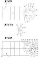
- the then separate sections 16, 17 are bent around the predetermined separation points 13, 14, which extend substantially on a radial line through the center 5. It arises in the FIGS. 3 and 3a illustrated state, namely an opening 22 whose opening width corresponds approximately to the diameter of the minimum contour line of the window 11. Since the dividing lines 13, 14 extend on radial lines through the center 5, a V-shaped opening 22 is formed, with which the tool can be plugged onto an output shaft of a drive machine in the radial direction.
- the opening 22 is open to the outside, so the window 11 connects to the outside, which is after breaking out of the breakaway 16,17 forming opening 22 in the embodiment of FIG. 5 to a recess 23 open.
- the recess 23 is encircled, but has a larger area than the surface of the window 11.
- To the recess 23 is located in an oblique to the window 11 forming portion extending portion of the sheet.
- a holding nut having a portion of an output shaft of the prime mover can be inserted through. With this retaining nut, the drive profile can be attached to an output profile of the drive machine.
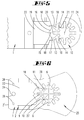
- FIG. 6 illustrated embodiment corresponds to the design of the window 11 and the predetermined separation points 13 to 15 and the Ausbrechabête 16,17 in the FIG. 5 illustrated embodiment. Essential to that in the FIG. 6 illustrated embodiment, but the compensation mass 25th
- a center line 24 extends transversely through a peripheral edge of an attachment point 2 ', to which on the drive portion 2, a working portion 1 can be attached, which has a saw toothing or the like.
- the center line 24 passes through the center of the window 11, which is defined by the axis 5.
- a mass accumulation is provided on the attachment site 2 'opposite side of the drive section 2 . It is a compensation mass 25, which is formed by a broadening of the sheet in the circumferential direction. The local wall of the window 11 is also widened in the direction away from the attachment point 2 '. As a result, the center of gravity 27 of the drive section 2 lies in the center of the window 11.
- mass defects In the area between the center of the window 11 and the attachment point 2 ', there may be mass defects. These can be realized by indentations 28 in the outer edge of the drive section 2 be. Preferably, however, the mass imperfections are formed by a surrounding recess 23, through which the center line 24 extends.
- the tool receives a center of gravity that is offset with respect to the axis 5 towards the working section 1.
- the compensation mass 25 gives the tool a 20- to 25-percent balance.
- a plurality of predetermined breaking lines extend in the radial direction, in which in the FIG. 7 illustrated embodiment, that the predetermined breaking line B along a tangential, based on an axis 5 placed around the circular arc line, wherein the axis 5 forms the center of the arranged on a circular arc form-fitting engagement openings 6 to 10.
- a radial R passing through the oscillation center 5 of the tool intersects the predetermined breaking line B at right angles in the middle of the breaking-out section 16.
- the predetermined breaking line B extends through two webs 13, which each connect a fastening side of the breaking-out section 16 to the frame 12 of the window 11.
- the two attachment sides are inclined at an angle to each other approximately on V-shaped radials, of which the radial line R intersecting the predetermined breaking line B is an angle bisector.
- an incision 18 connects, which is radially outward, so open to the peripheral contour line of the drive section 2. At the edge of this edge opposite the edge is also followed by a cut 21, but the free surface of the Window 11 is open. This incision 21 also forms a form-fitting engagement opening 10.
- the predetermined breaking line B forms a bending line.
- the jaws of a pair of pliers may engage the broadside sides of the breakout portion 16 facing away from each other and bend the breakout portion 16 back and forth about the bend line B until material fatigue in the legs 13 causes it to break.
- a tool which is characterized in that the frame 12 of the window 11 has predetermined separation points 13 to 15 for breaking out a breaking-off section 16, 17.
- a tool which is characterized in that the predetermined separation points 13 to 15 are formed by webs which delimit a form-fitting engagement opening 9, 10.
- a tool which is characterized in that the predetermined separation points 13 to 15 are formed by webs which form peripheral edges which are formed by cuts 18 to 21 in the frame 12 of the window 11.
- a tool which is characterized in that the Ausbrechabites has two at a predetermined separation point 15 interconnected portions 16, 17.
- a tool which is characterized in that the width of an opening 22 formed by the separation of the breaking-off section 16, 17 from the window 11 corresponds to at least a minimum diameter of the window 11.
- a tool which is characterized in that the opening 22 formed by the breaking out of the breaking portions 16, 17 is arranged symmetrically with respect to an axis of symmetry 24 of the tool or of the drive section 2.
- a tool which is characterized in that the opening 22 formed by the breaking out of the breaking-off section 16, 17 is arranged laterally offset relative to an axis of symmetry 24 of the tool or of the drive section 2.
- a tool which is characterized in that the opening 22 formed by the breaking out of the break-off section 16, 17 allows radial attachment of the tool to a drive axle of the drive machine.
- a tool which is characterized in that the opening 22 formed by the breaking out of the break-off section 16, 17 connects the outer space around the tool or a recess 23 in the drive section 2 to the window 11.
- a tool which is characterized in that, relative to a midpoint defined by the axis 5 center line 24 of the attachment point 2 'opposite side of the drive section has such a mass distribution that the center of gravity 27 of the drive section 2 in the center or based on the attachment point 2 'beyond the center on the center line 24 is located.
- a tool which is characterized in that the fastening point 2 'opposite side of the drive portion 2 has a compensation mass 25.
- a tool which is characterized in that the compensation mass 25 is created by a widening of the sheet.
- each of the two facing apart mounting sides of the Ausbrechabiteses 16 is connected to the frame 12 with only one of the predetermined separation point forming web 13, wherein each web 13 to a free edge of the frame 12 radially outer cut 18 and adjacent to a window 11 free incision 10, 21 adjacent.
Landscapes
- Engineering & Computer Science (AREA)
- Mechanical Engineering (AREA)
- Working Measures On Existing Buildindgs (AREA)
- Harvester Elements (AREA)
- Shovels (AREA)
Applications Claiming Priority (2)
| Application Number | Priority Date | Filing Date | Title |
|---|---|---|---|
| DE102014117119 | 2014-11-24 | ||
| DE102015119962.9A DE102015119962A1 (de) | 2014-11-24 | 2015-11-18 | Um eine Oszillations- oder Drehachse drehantreibbares Werkzeug mit einem Antriebsprofil zur Kupplung mit einem Abtriebsprofil |
Publications (3)
| Publication Number | Publication Date |
|---|---|
| EP3023185A2 true EP3023185A2 (fr) | 2016-05-25 |
| EP3023185A3 EP3023185A3 (fr) | 2016-08-03 |
| EP3023185B1 EP3023185B1 (fr) | 2021-02-24 |
Family
ID=54780060
Family Applications (1)
| Application Number | Title | Priority Date | Filing Date |
|---|---|---|---|
| EP15195574.7A Active EP3023185B1 (fr) | 2014-11-24 | 2015-11-20 | Outil entraîné en rotation autour d'un axe de rotation ou d'oscillation comprenant un profil d'entraînement destiné a s'accoupler à un profil d'entraînement |
Country Status (1)
| Country | Link |
|---|---|
| EP (1) | EP3023185B1 (fr) |
Cited By (5)
| Publication number | Priority date | Publication date | Assignee | Title |
|---|---|---|---|---|
| USD931069S1 (en) | 2019-05-03 | 2021-09-21 | Tti (Macao Commercial Offshore) Limited | Blade |
| USD953833S1 (en) | 2019-08-22 | 2022-06-07 | Milwaukee Electric Tool Corporation | Oscillating multi tool anchor |
| US11738398B2 (en) | 2020-11-18 | 2023-08-29 | Milwaukee Electric Tool Corporation | Accessory for an oscillating power tool |
| USD1048844S1 (en) | 2022-07-22 | 2024-10-29 | Milwaukee Electric Tool Corporation | Anchor for an accessory attachable to an oscillating multi-tool |
| USD1101531S1 (en) | 2019-08-22 | 2025-11-11 | Milwaukee Electric Tool Corporation | Oscillating multi tool anchor |
Citations (6)
| Publication number | Priority date | Publication date | Assignee | Title |
|---|---|---|---|---|
| US6022353A (en) | 1991-05-30 | 2000-02-08 | Synasive Technology, Inc. | Surgical saw blade |
| DE102004050798A1 (de) | 2004-10-19 | 2006-04-20 | Robert Bosch Gmbh | Vorrichtung zum Befestigen eines Werkzeugs an einer oszillierend antreibbaren Antriebswelle einer Handwerkzeugmaschine |
| DE202010013008U1 (de) | 2010-11-29 | 2011-02-10 | Ho, Yen-Ju, Taiping City | Spannvorrichtung eines Antriebswerkzeugs |
| DE202011000517U1 (de) | 2010-03-19 | 2011-08-11 | Chervon (Hk) Limited | Adapter für Multifunktionswerkzeug |
| DE202011052299U1 (de) | 2010-12-14 | 2012-02-06 | Techtronic Power Tools Technology Ltd. | Universelle Schnittstelle für Klingenzubehörteile |
| US8523868B2 (en) | 2008-06-11 | 2013-09-03 | Medtronic Ps Medical, Inc. | Surgical cutting instrument with dual surface interlocking coupling arrangement |
Family Cites Families (3)
| Publication number | Priority date | Publication date | Assignee | Title |
|---|---|---|---|---|
| DE102008041425A1 (de) * | 2008-08-21 | 2010-02-25 | Robert Bosch Gmbh | Werkzeug |
| DE102010039786A1 (de) * | 2010-08-26 | 2012-03-01 | Robert Bosch Gmbh | System mit zumindest zwei Oszillationseinsatzwerkzeugen |
| US9815187B2 (en) * | 2014-03-21 | 2017-11-14 | Burton Kozak | Tool accessory having a partially removable attachment portion |
-
2015
- 2015-11-20 EP EP15195574.7A patent/EP3023185B1/fr active Active
Patent Citations (6)
| Publication number | Priority date | Publication date | Assignee | Title |
|---|---|---|---|---|
| US6022353A (en) | 1991-05-30 | 2000-02-08 | Synasive Technology, Inc. | Surgical saw blade |
| DE102004050798A1 (de) | 2004-10-19 | 2006-04-20 | Robert Bosch Gmbh | Vorrichtung zum Befestigen eines Werkzeugs an einer oszillierend antreibbaren Antriebswelle einer Handwerkzeugmaschine |
| US8523868B2 (en) | 2008-06-11 | 2013-09-03 | Medtronic Ps Medical, Inc. | Surgical cutting instrument with dual surface interlocking coupling arrangement |
| DE202011000517U1 (de) | 2010-03-19 | 2011-08-11 | Chervon (Hk) Limited | Adapter für Multifunktionswerkzeug |
| DE202010013008U1 (de) | 2010-11-29 | 2011-02-10 | Ho, Yen-Ju, Taiping City | Spannvorrichtung eines Antriebswerkzeugs |
| DE202011052299U1 (de) | 2010-12-14 | 2012-02-06 | Techtronic Power Tools Technology Ltd. | Universelle Schnittstelle für Klingenzubehörteile |
Cited By (6)
| Publication number | Priority date | Publication date | Assignee | Title |
|---|---|---|---|---|
| USD931069S1 (en) | 2019-05-03 | 2021-09-21 | Tti (Macao Commercial Offshore) Limited | Blade |
| USD1015098S1 (en) | 2019-05-03 | 2024-02-20 | Techtronic Power Tools Technology Limited | Blade |
| USD953833S1 (en) | 2019-08-22 | 2022-06-07 | Milwaukee Electric Tool Corporation | Oscillating multi tool anchor |
| USD1101531S1 (en) | 2019-08-22 | 2025-11-11 | Milwaukee Electric Tool Corporation | Oscillating multi tool anchor |
| US11738398B2 (en) | 2020-11-18 | 2023-08-29 | Milwaukee Electric Tool Corporation | Accessory for an oscillating power tool |
| USD1048844S1 (en) | 2022-07-22 | 2024-10-29 | Milwaukee Electric Tool Corporation | Anchor for an accessory attachable to an oscillating multi-tool |
Also Published As
| Publication number | Publication date |
|---|---|
| EP3023185A3 (fr) | 2016-08-03 |
| EP3023185B1 (fr) | 2021-02-24 |
Similar Documents
| Publication | Publication Date | Title |
|---|---|---|
| EP4219072B1 (fr) | Système d'outil | |
| EP2475897B1 (fr) | Système d'entraînement en rotation | |
| EP3023185B1 (fr) | Outil entraîné en rotation autour d'un axe de rotation ou d'oscillation comprenant un profil d'entraînement destiné a s'accoupler à un profil d'entraînement | |
| DE102010015404B4 (de) | Verfahren zur Reparatur einer Rotoranordnung einer Turbomaschine, Ringelement für eine Rotoranordnung einer Turbomaschine sowie Rotoranordnung für eine Turbomaschine | |
| EP2987577A1 (fr) | Scie a guichet | |
| EP2218829B1 (fr) | Dent de fraisage pour une fraise pour paroi moulée | |
| EP3213847A1 (fr) | Outil d'oscillation | |
| DE3033909C2 (de) | Verbindungselement | |
| EP4313490B1 (fr) | Tête d'outil pour un outil | |
| EP1178232B1 (fr) | Elément entraineur à bride pour joint de cardan et arbre articulé | |
| EP2420717B1 (fr) | Revêtement de protection variable en longueur et lamelle en acier pour celui-ci | |
| DE10236295A1 (de) | Hoch-drehelastische Wellenkupplung und Verfahren zu ihrer Herstellung | |
| EP3735541B1 (fr) | Dispositif de fixation | |
| DE102015119962A1 (de) | Um eine Oszillations- oder Drehachse drehantreibbares Werkzeug mit einem Antriebsprofil zur Kupplung mit einem Abtriebsprofil | |
| DE102020003346B3 (de) | Umfangsstabmesserkopf | |
| EP2915613B1 (fr) | Foret à trou transversal | |
| DE69024165T2 (de) | Schneidkette | |
| DE212014000020U1 (de) | Bearbeitungssystem | |
| AT504993A1 (de) | Schneidplatte für radsatzbearbeitungswerkzeuge | |
| EP3477127A1 (fr) | Vis destinée à être vissée dans un trou de forage | |
| EP3784440B1 (fr) | Pince | |
| EP1715975B1 (fr) | Fraise a vitesse elevee | |
| DE19959677B4 (de) | Verfahren und Vorrichtung zum Bruchtrennen von ringförmigen Werkstücken | |
| DE102009011330A1 (de) | Rundmesser für eine Messerwelle einer Schneidvorrichtung | |
| EP2913128A1 (fr) | Outil et procédé d'usinage d'une extrémité d'un élément tubulaire |
Legal Events
| Date | Code | Title | Description |
|---|---|---|---|
| AK | Designated contracting states |
Kind code of ref document: A2 Designated state(s): AL AT BE BG CH CY CZ DE DK EE ES FI FR GB GR HR HU IE IS IT LI LT LU LV MC MK MT NL NO PL PT RO RS SE SI SK SM TR |
|
| AX | Request for extension of the european patent |
Extension state: BA ME |
|
| PUAI | Public reference made under article 153(3) epc to a published international application that has entered the european phase |
Free format text: ORIGINAL CODE: 0009012 |
|
| PUAL | Search report despatched |
Free format text: ORIGINAL CODE: 0009013 |
|
| AK | Designated contracting states |
Kind code of ref document: A3 Designated state(s): AL AT BE BG CH CY CZ DE DK EE ES FI FR GB GR HR HU IE IS IT LI LT LU LV MC MK MT NL NO PL PT RO RS SE SI SK SM TR |
|
| AX | Request for extension of the european patent |
Extension state: BA ME |
|
| RIC1 | Information provided on ipc code assigned before grant |
Ipc: B23D 61/00 20060101AFI20160628BHEP Ipc: B24B 23/04 20060101ALI20160628BHEP Ipc: B23D 61/02 20060101ALI20160628BHEP Ipc: B24B 45/00 20060101ALI20160628BHEP |
|
| STAA | Information on the status of an ep patent application or granted ep patent |
Free format text: STATUS: REQUEST FOR EXAMINATION WAS MADE |
|
| 17P | Request for examination filed |
Effective date: 20161118 |
|
| RBV | Designated contracting states (corrected) |
Designated state(s): AL AT BE BG CH CY CZ DE DK EE ES FI FR GB GR HR HU IE IS IT LI LT LU LV MC MK MT NL NO PL PT RO RS SE SI SK SM TR |
|
| GRAP | Despatch of communication of intention to grant a patent |
Free format text: ORIGINAL CODE: EPIDOSNIGR1 |
|
| STAA | Information on the status of an ep patent application or granted ep patent |
Free format text: STATUS: GRANT OF PATENT IS INTENDED |
|
| INTG | Intention to grant announced |
Effective date: 20200922 |
|
| GRAS | Grant fee paid |
Free format text: ORIGINAL CODE: EPIDOSNIGR3 |
|
| GRAA | (expected) grant |
Free format text: ORIGINAL CODE: 0009210 |
|
| STAA | Information on the status of an ep patent application or granted ep patent |
Free format text: STATUS: THE PATENT HAS BEEN GRANTED |
|
| AK | Designated contracting states |
Kind code of ref document: B1 Designated state(s): AL AT BE BG CH CY CZ DE DK EE ES FI FR GB GR HR HU IE IS IT LI LT LU LV MC MK MT NL NO PL PT RO RS SE SI SK SM TR |
|
| REG | Reference to a national code |
Ref country code: GB Ref legal event code: FG4D Free format text: NOT ENGLISH |
|
| REG | Reference to a national code |
Ref country code: CH Ref legal event code: EP |
|
| REG | Reference to a national code |
Ref country code: AT Ref legal event code: REF Ref document number: 1363828 Country of ref document: AT Kind code of ref document: T Effective date: 20210315 |
|
| REG | Reference to a national code |
Ref country code: IE Ref legal event code: FG4D Free format text: LANGUAGE OF EP DOCUMENT: GERMAN |
|
| REG | Reference to a national code |
Ref country code: DE Ref legal event code: R096 Ref document number: 502015014284 Country of ref document: DE |
|
| REG | Reference to a national code |
Ref country code: LT Ref legal event code: MG9D |
|
| REG | Reference to a national code |
Ref country code: NL Ref legal event code: MP Effective date: 20210224 |
|
| PG25 | Lapsed in a contracting state [announced via postgrant information from national office to epo] |
Ref country code: PT Free format text: LAPSE BECAUSE OF FAILURE TO SUBMIT A TRANSLATION OF THE DESCRIPTION OR TO PAY THE FEE WITHIN THE PRESCRIBED TIME-LIMIT Effective date: 20210624 Ref country code: LT Free format text: LAPSE BECAUSE OF FAILURE TO SUBMIT A TRANSLATION OF THE DESCRIPTION OR TO PAY THE FEE WITHIN THE PRESCRIBED TIME-LIMIT Effective date: 20210224 Ref country code: GR Free format text: LAPSE BECAUSE OF FAILURE TO SUBMIT A TRANSLATION OF THE DESCRIPTION OR TO PAY THE FEE WITHIN THE PRESCRIBED TIME-LIMIT Effective date: 20210525 Ref country code: FI Free format text: LAPSE BECAUSE OF FAILURE TO SUBMIT A TRANSLATION OF THE DESCRIPTION OR TO PAY THE FEE WITHIN THE PRESCRIBED TIME-LIMIT Effective date: 20210224 Ref country code: HR Free format text: LAPSE BECAUSE OF FAILURE TO SUBMIT A TRANSLATION OF THE DESCRIPTION OR TO PAY THE FEE WITHIN THE PRESCRIBED TIME-LIMIT Effective date: 20210224 Ref country code: BG Free format text: LAPSE BECAUSE OF FAILURE TO SUBMIT A TRANSLATION OF THE DESCRIPTION OR TO PAY THE FEE WITHIN THE PRESCRIBED TIME-LIMIT Effective date: 20210524 Ref country code: NO Free format text: LAPSE BECAUSE OF FAILURE TO SUBMIT A TRANSLATION OF THE DESCRIPTION OR TO PAY THE FEE WITHIN THE PRESCRIBED TIME-LIMIT Effective date: 20210524 |
|
| PG25 | Lapsed in a contracting state [announced via postgrant information from national office to epo] |
Ref country code: RS Free format text: LAPSE BECAUSE OF FAILURE TO SUBMIT A TRANSLATION OF THE DESCRIPTION OR TO PAY THE FEE WITHIN THE PRESCRIBED TIME-LIMIT Effective date: 20210224 Ref country code: LV Free format text: LAPSE BECAUSE OF FAILURE TO SUBMIT A TRANSLATION OF THE DESCRIPTION OR TO PAY THE FEE WITHIN THE PRESCRIBED TIME-LIMIT Effective date: 20210224 Ref country code: PL Free format text: LAPSE BECAUSE OF FAILURE TO SUBMIT A TRANSLATION OF THE DESCRIPTION OR TO PAY THE FEE WITHIN THE PRESCRIBED TIME-LIMIT Effective date: 20210224 Ref country code: NL Free format text: LAPSE BECAUSE OF FAILURE TO SUBMIT A TRANSLATION OF THE DESCRIPTION OR TO PAY THE FEE WITHIN THE PRESCRIBED TIME-LIMIT Effective date: 20210224 Ref country code: SE Free format text: LAPSE BECAUSE OF FAILURE TO SUBMIT A TRANSLATION OF THE DESCRIPTION OR TO PAY THE FEE WITHIN THE PRESCRIBED TIME-LIMIT Effective date: 20210224 |
|
| PG25 | Lapsed in a contracting state [announced via postgrant information from national office to epo] |
Ref country code: IS Free format text: LAPSE BECAUSE OF FAILURE TO SUBMIT A TRANSLATION OF THE DESCRIPTION OR TO PAY THE FEE WITHIN THE PRESCRIBED TIME-LIMIT Effective date: 20210624 |
|
| PG25 | Lapsed in a contracting state [announced via postgrant information from national office to epo] |
Ref country code: CZ Free format text: LAPSE BECAUSE OF FAILURE TO SUBMIT A TRANSLATION OF THE DESCRIPTION OR TO PAY THE FEE WITHIN THE PRESCRIBED TIME-LIMIT Effective date: 20210224 Ref country code: EE Free format text: LAPSE BECAUSE OF FAILURE TO SUBMIT A TRANSLATION OF THE DESCRIPTION OR TO PAY THE FEE WITHIN THE PRESCRIBED TIME-LIMIT Effective date: 20210224 Ref country code: SM Free format text: LAPSE BECAUSE OF FAILURE TO SUBMIT A TRANSLATION OF THE DESCRIPTION OR TO PAY THE FEE WITHIN THE PRESCRIBED TIME-LIMIT Effective date: 20210224 |
|
| REG | Reference to a national code |
Ref country code: DE Ref legal event code: R097 Ref document number: 502015014284 Country of ref document: DE |
|
| PG25 | Lapsed in a contracting state [announced via postgrant information from national office to epo] |
Ref country code: SK Free format text: LAPSE BECAUSE OF FAILURE TO SUBMIT A TRANSLATION OF THE DESCRIPTION OR TO PAY THE FEE WITHIN THE PRESCRIBED TIME-LIMIT Effective date: 20210224 Ref country code: RO Free format text: LAPSE BECAUSE OF FAILURE TO SUBMIT A TRANSLATION OF THE DESCRIPTION OR TO PAY THE FEE WITHIN THE PRESCRIBED TIME-LIMIT Effective date: 20210224 Ref country code: DK Free format text: LAPSE BECAUSE OF FAILURE TO SUBMIT A TRANSLATION OF THE DESCRIPTION OR TO PAY THE FEE WITHIN THE PRESCRIBED TIME-LIMIT Effective date: 20210224 Ref country code: ES Free format text: LAPSE BECAUSE OF FAILURE TO SUBMIT A TRANSLATION OF THE DESCRIPTION OR TO PAY THE FEE WITHIN THE PRESCRIBED TIME-LIMIT Effective date: 20210224 |
|
| PLBE | No opposition filed within time limit |
Free format text: ORIGINAL CODE: 0009261 |
|
| STAA | Information on the status of an ep patent application or granted ep patent |
Free format text: STATUS: NO OPPOSITION FILED WITHIN TIME LIMIT |
|
| PG25 | Lapsed in a contracting state [announced via postgrant information from national office to epo] |
Ref country code: AL Free format text: LAPSE BECAUSE OF FAILURE TO SUBMIT A TRANSLATION OF THE DESCRIPTION OR TO PAY THE FEE WITHIN THE PRESCRIBED TIME-LIMIT Effective date: 20210224 |
|
| 26N | No opposition filed |
Effective date: 20211125 |
|
| PG25 | Lapsed in a contracting state [announced via postgrant information from national office to epo] |
Ref country code: SI Free format text: LAPSE BECAUSE OF FAILURE TO SUBMIT A TRANSLATION OF THE DESCRIPTION OR TO PAY THE FEE WITHIN THE PRESCRIBED TIME-LIMIT Effective date: 20210224 |
|
| PG25 | Lapsed in a contracting state [announced via postgrant information from national office to epo] |
Ref country code: IT Free format text: LAPSE BECAUSE OF FAILURE TO SUBMIT A TRANSLATION OF THE DESCRIPTION OR TO PAY THE FEE WITHIN THE PRESCRIBED TIME-LIMIT Effective date: 20210224 |
|
| PG25 | Lapsed in a contracting state [announced via postgrant information from national office to epo] |
Ref country code: IS Free format text: LAPSE BECAUSE OF FAILURE TO SUBMIT A TRANSLATION OF THE DESCRIPTION OR TO PAY THE FEE WITHIN THE PRESCRIBED TIME-LIMIT Effective date: 20210624 |
|
| PG25 | Lapsed in a contracting state [announced via postgrant information from national office to epo] |
Ref country code: MC Free format text: LAPSE BECAUSE OF FAILURE TO SUBMIT A TRANSLATION OF THE DESCRIPTION OR TO PAY THE FEE WITHIN THE PRESCRIBED TIME-LIMIT Effective date: 20210224 |
|
| REG | Reference to a national code |
Ref country code: CH Ref legal event code: PL |
|
| GBPC | Gb: european patent ceased through non-payment of renewal fee |
Effective date: 20211120 |
|
| PG25 | Lapsed in a contracting state [announced via postgrant information from national office to epo] |
Ref country code: LU Free format text: LAPSE BECAUSE OF NON-PAYMENT OF DUE FEES Effective date: 20211120 Ref country code: BE Free format text: LAPSE BECAUSE OF NON-PAYMENT OF DUE FEES Effective date: 20211130 |
|
| REG | Reference to a national code |
Ref country code: BE Ref legal event code: MM Effective date: 20211130 |
|
| PG25 | Lapsed in a contracting state [announced via postgrant information from national office to epo] |
Ref country code: IE Free format text: LAPSE BECAUSE OF NON-PAYMENT OF DUE FEES Effective date: 20211120 Ref country code: GB Free format text: LAPSE BECAUSE OF NON-PAYMENT OF DUE FEES Effective date: 20211120 |
|
| REG | Reference to a national code |
Ref country code: AT Ref legal event code: MM01 Ref document number: 1363828 Country of ref document: AT Kind code of ref document: T Effective date: 20211120 |
|
| PG25 | Lapsed in a contracting state [announced via postgrant information from national office to epo] |
Ref country code: AT Free format text: LAPSE BECAUSE OF NON-PAYMENT OF DUE FEES Effective date: 20211120 |
|
| PG25 | Lapsed in a contracting state [announced via postgrant information from national office to epo] |
Ref country code: HU Free format text: LAPSE BECAUSE OF FAILURE TO SUBMIT A TRANSLATION OF THE DESCRIPTION OR TO PAY THE FEE WITHIN THE PRESCRIBED TIME-LIMIT; INVALID AB INITIO Effective date: 20151120 |
|
| P01 | Opt-out of the competence of the unified patent court (upc) registered |
Effective date: 20230513 |
|
| PG25 | Lapsed in a contracting state [announced via postgrant information from national office to epo] |
Ref country code: CY Free format text: LAPSE BECAUSE OF FAILURE TO SUBMIT A TRANSLATION OF THE DESCRIPTION OR TO PAY THE FEE WITHIN THE PRESCRIBED TIME-LIMIT Effective date: 20210224 |
|
| PG25 | Lapsed in a contracting state [announced via postgrant information from national office to epo] |
Ref country code: LI Free format text: LAPSE BECAUSE OF NON-PAYMENT OF DUE FEES Effective date: 20220701 Ref country code: CH Free format text: LAPSE BECAUSE OF NON-PAYMENT OF DUE FEES Effective date: 20220701 |
|
| PG25 | Lapsed in a contracting state [announced via postgrant information from national office to epo] |
Ref country code: MK Free format text: LAPSE BECAUSE OF FAILURE TO SUBMIT A TRANSLATION OF THE DESCRIPTION OR TO PAY THE FEE WITHIN THE PRESCRIBED TIME-LIMIT Effective date: 20210224 |
|
| PG25 | Lapsed in a contracting state [announced via postgrant information from national office to epo] |
Ref country code: TR Free format text: LAPSE BECAUSE OF FAILURE TO SUBMIT A TRANSLATION OF THE DESCRIPTION OR TO PAY THE FEE WITHIN THE PRESCRIBED TIME-LIMIT Effective date: 20210224 |
|
| PG25 | Lapsed in a contracting state [announced via postgrant information from national office to epo] |
Ref country code: MT Free format text: LAPSE BECAUSE OF FAILURE TO SUBMIT A TRANSLATION OF THE DESCRIPTION OR TO PAY THE FEE WITHIN THE PRESCRIBED TIME-LIMIT Effective date: 20210224 |
|
| PGFP | Annual fee paid to national office [announced via postgrant information from national office to epo] |
Ref country code: DE Payment date: 20251119 Year of fee payment: 11 |
|
| PGFP | Annual fee paid to national office [announced via postgrant information from national office to epo] |
Ref country code: FR Payment date: 20251118 Year of fee payment: 11 |