EP3023548A1 - Steinkorb - Google Patents
Steinkorb Download PDFInfo
- Publication number
- EP3023548A1 EP3023548A1 EP15186578.9A EP15186578A EP3023548A1 EP 3023548 A1 EP3023548 A1 EP 3023548A1 EP 15186578 A EP15186578 A EP 15186578A EP 3023548 A1 EP3023548 A1 EP 3023548A1
- Authority
- EP
- European Patent Office
- Prior art keywords
- wall
- stone basket
- side walls
- connecting wires
- partition
- Prior art date
- Legal status (The legal status is an assumption and is not a legal conclusion. Google has not performed a legal analysis and makes no representation as to the accuracy of the status listed.)
- Granted
Links
- 239000004575 stone Substances 0.000 claims abstract description 47
- 238000000034 method Methods 0.000 claims abstract description 9
- 238000005192 partition Methods 0.000 claims description 18
- 238000005429 filling process Methods 0.000 description 1
- 230000003068 static effect Effects 0.000 description 1
Images

Classifications
-
- E—FIXED CONSTRUCTIONS
- E02—HYDRAULIC ENGINEERING; FOUNDATIONS; SOIL SHIFTING
- E02D—FOUNDATIONS; EXCAVATIONS; EMBANKMENTS; UNDERGROUND OR UNDERWATER STRUCTURES
- E02D29/00—Independent underground or underwater structures; Retaining walls
- E02D29/02—Retaining or protecting walls
- E02D29/0208—Gabions
Definitions
- the invention relates to a stone basket, in particular a gabion, according to the preamble of claim 1, consisting at least of interconnected side walls of wire, namely at least two lateral side walls, a front wall and a rear wall and a bottom wall and a top wall, as for example in DE 39 17 756 A1 are described.
- the invention further relates to a method for filling a gabion.
- a stone basket according to claim 1 comprising its characterizing features as well as a method for filling a stone basket according to claim 7. Furthermore, the invention has produced a lifting attachment according to claim 5.
- a partition of horizontal and transversely arranged thereon connecting elements inside the Gabion provides for internal stiffening, has the advantage that the horizontally provided as tension elements after filling connecting wires or rods are connected in the transverse direction and thus stiffened.
- the wires exposed to rockfall during the filling process, usually unprotected, are stabilized, in particular when the transverse connectors according to the invention are welded to the horizontal wires according to an advantageous embodiment.
- the lifting attachment which has been developed for this purpose, can be hung by a lever movement from a rest position to a vertical Einhnature, wherein a wire of the top wall and a cross-connector are engaged behind.
- a lifting attachment according to an advantageous embodiment braces horizontal wires when hanging against each other, so that the Einhticiananbauteil without force application not again falls back to its rest position. This is advantageous when hooked by means of an excavator because no worker must hold a releasably mounted hook in the danger area in position for hanging.
- FIGS. 1 and 2 show an embodiment of the invention as indicated in the claims. Of course, other embodiments, which are not shown in the drawing, fall within the scope.
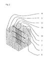
- a stone basket for example a gabion, usually consists of at least interconnected side walls made of wire. Also, the illustrated embodiment shows two lateral side walls 2, 4, a front wall 5 and a rear wall 3 in a vertical orientation. Horizontally oriented and connected with their edges with the side walls at the top or bottom are a bottom wall 6 and a top wall. 7 FIG. 1 shows the top wall 7 of an open stone basket. In FIG. 2 the top wall is shown in a closed state of the stone basket, as it is usually taken for transport purposes or after filling with stones, for example.
- a partition wall 10, here made of wire is inserted approximately centrally into the stone basket.
- the partition wall 10 consists of horizontal connecting wires 12 extending horizontally between the lateral side walls 2, 4. Transverse thereto, further connecting wires 15 according to the illustrated embodiment are arranged in the vertical direction and welded to the horizontal connectors 12.
- the partition wall thus formed connects the horizontal connecting wires 12 with the bottom wall 6 and supports them in the vertical direction. Furthermore, the vertical connectors divert falling stones, so that the horizontal connectors do not tend to shorten significantly.
- a top horizontal connecting wire 12 extends just below the top wall 7.
- the vertical connectors are particularly advantageous later linked to the top wall. This results in vertical side wall connectors that stabilize the same in then new lateral direction against buckling in a tipping over the stone basket.
- all the side walls 2, 3, 4, 5, 6, 7 of connecting wires and / or rods of the same strength and type of connection are identical to all the side walls 2, 3, 4, 5, 6, 7 of connecting wires and / or rods of the same strength and type of connection.
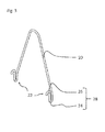
- An inventive lifting attachment 20 for lifting the stone basket is exemplary in FIG. 3 shown. It points two lower hanging on 22, which are intended to enclose a connecting wire or rod of stone basket with a V-shape 24 only partially. Subsequently, a further V-shape 26 is configured on the V-shape 24, so that an S-shape 28 results from the two V-shapes.
- a method for filling a stone basket has the following process types.
- the horizontal connecting wires tensioned and / or rods 12 used and connected to each other and to the bottom wall 6 in the vertical direction 15.
- at least a partition wall 10 thus formed between at least two of the lateral side walls 2, 3, 4, 5 used and connected to the bottom wall 6, before the gabion is filled with stones or the like.
- the top wall 7 is closed after filling the stone basket with stones, for example, and connected to the partition 10. This advantageously takes place with further connecting wires and / or bars 15 of the dividing wall 10 extending transversely to the horizontal connecting wires 12.
- the lifting attachment 20 regardless of whether in the original position of the stone basket or after tilting the same by 90 ° centered in an actual top side wall element 2, 3, 4, 5, 6, 7 are mounted, at least with its first V-shape 24.
- a stiffening wire further inside the stone basket and can be provided secured for lifting.
Landscapes
- Engineering & Computer Science (AREA)
- Environmental & Geological Engineering (AREA)
- Life Sciences & Earth Sciences (AREA)
- General Life Sciences & Earth Sciences (AREA)
- Mining & Mineral Resources (AREA)
- Paleontology (AREA)
- Civil Engineering (AREA)
- General Engineering & Computer Science (AREA)
- Structural Engineering (AREA)
- Revetment (AREA)
- Pit Excavations, Shoring, Fill Or Stabilisation Of Slopes (AREA)
Abstract
Description
- Die Erfindung betrifft einen Steinkorb, insbesondere eine Gabione, gemäß dem Oberbegriff des Anspruchs 1, bestehend zumindest aus miteinander verbundenen Seitenwänden aus Draht, nämlich zumindest zwei seitlichen Seitenwänden, einer Vorderwand und einer Rückwand sowie einer Bodenwand und einer Deckwand, wie sie beispielsweise in
DE 39 17 756 A1 beschrieben sind. Die Erfindung betrifft ferner ein Verfahren zum Befüllen einer Gabione. - Beim Befüllen solcher Steinkörbe beispielsweise mit Steinen neigen die seitlichen Seitenwände dazu, sich mit ihrer ursprünglichen Flächenmitte nach außen drücken zu lassen. Dem begegnet man bekanntermaßen mit horizontalen Verbindungsdrähten, die im Inneren des Steinkorbs die seitlichen Seitenwände verbinden oder verspannen.
- Beim Befüllen solcher Steinkörbe mit inneren Seitenverbindern mit Steinen werden die horizontalen Drähte oft von Steinen getroffen und verformt und im Ergebnis verkürzt, die recht unberechenbar. Seitliche Seitenwände können nach dem Befüllen nun nach innen verjüngt oder konkav resultieren.
- Es gilt daher nach wie vor, die Formstabilität der Steinkörbe zu verbessern.
- Dieses Problem wird gelöst durch einen Steinkorb gemäß Anspruch 1 umfassend seine kennzeichnenden Merkmale wie auch ein Verfahren zum Befüllen eines Steinkorbs gemäß Anspruch 7. Weiterhin hat die Erfindung ein Hebeanbauteil gemäß Anspruch 5 hervorgebracht.
- Als Erfolg der Erfindung, die eine Trennwand aus horizontalen und quer dazu angeordneten Verbindungselementen im Inneren der Gabione zum inneren Aussteifen vorsieht, hat den Vorteil, dass die horizontal als Zugelemente nach einem Befüllen vorgesehenen Verbindungsdrähte oder -stäbe in Querrichtung verbunden und damit ausgesteift werden. Die beim Befüllvorgang horizontal gewöhnlich ungeschützt dem Steinschlag ausgesetzten Drähte sind stabilisiert, insbesondere wenn die erfindungsgemäßen Querverbinder gemäß einer vorteilhaften Ausführungsform mit den Horizontaldrähten verschweißt sind.
- Dem Grundgedanken der Erfindung folgend hat sich die weitere Idee entwickelt, dass auch Vertikalverbinder zwischen der ursprünglichen Bodenwand und Deckwand aus den Querverbindern abgeleitet werden können. Die statischen Vorteile gelten dann nämlich auch für den Fall, dass ein Steinkorb auf eine ursprüngliche seitliche Seitenwand als neue Bondenwand gelegt werden soll. Dann ist es vorteilhaft, dass Vertikalverbinder Zugkräfte aufnehmen können und ein Ausbeulen verhindern.
- Dem Grundgedanken der Erfindung folgend wurde erkannt, dass eine vorteilhafte Möglichkeit zum Anheben durch einen gemäß einer vorteilhaften Ausführungsform nahe unterhalb der Deckwand verlaufenden Horizontalverbinder geboten ist. Dort kann nun angehoben werden, wie bei üblichen Steinkörben oft an deren oberen Ecken eingehängt worden ist. Die Zugkraft eines Hebeanbauteils wird über die Vertikalverbinder in die Bodenwand abgetragen. Die Querverbinder verhindern ein seitliches Ausbeulen. Der Steinkorb kann formstabil angehoben werden.
- Das Hebeanbauteil, der hierzu entwickelt worden ist, kann durch eine Hebelbewegung aus einer Ruhelage in eine vertikale Einhängstellung eingehängt werden, wobei ein Draht der Deckwand und ein Querverbinder hintergriffen werden. Ein Hebeanbauteil gemäß einer vorteilhaften Ausführungsform verspannt Horizonatldrähte beim Einhängen gegeneinander, sodass das Einhänganbauteil ohne Kraftanwendung nicht wieder in seine Ruhelage zurückfällt. Das ist beim Einhängen mittels eines Baggers von Vorteil, weil kein Arbeiter einen lösbar angebrachten Haken im Gefahrenbereich in Position zum Einhängen halten muss.
- Vorteilhafte Ausgestaltungen der Erfindung sind in den jeweiligen Unteransprüchen angegeben.
- Die Erfindung wird anhand von Figuren eingehender beschrieben.
- Es zeigen
- Figur 1
- einen Steinkorb mit Trennwand bei geöffneter Deckwand,
- Figur 2
- den Steinkorb aus
Figur 1 mit geschlossener Deckwand und - Figur 3
- ein Hebeanbauteil zum Einhängen in beispielsweise den Steinkorb aus den
Figuren 1 und2 in separater Darstellung. - Die
Figuren 1 und2 zeigen ein Ausführungsbeispiel der Erfindung, wie sie in den Patentansprüchen angegeben ist. Selbstverständlich fallen auch andere Ausgestaltungen, die nicht zeichnerisch dargestellt sind, in den Schutzbereich. - Ein Steinkorb, beispielsweise eine Gabione, besteht üblicherweise zumindest aus miteinander verbundenen Seitenwänden aus Draht. Auch das dargestellte Ausführungsbeispiel zeigt zwei seitliche Seitenwände 2, 4, eine Vorderwand 5 und eine Rückwand 3 in vertikaler Ausrichtung. Waagerecht ausgerichtet und mit ihren Rändern mit den seitlichen Seitenwänden oben oder unten verbunden sind eine Bodenwand 6 und eine Deckwand 7.
Figur 1 zeigt die Deckwand 7 eines geöffneten Steinkorbs. InFigur 2 ist die Deckwand in einem geschlossenen Zustand des Steinkorbs dargestellt, wie er in der Regel zu Transportzwecken oder nach einem Befüllen mit beispielsweise Steinen eingenommen wird. - Erfindungsgemäß ist eine Trennwand 10, hier aus Draht, etwa mittig in den Steinkorb eingesetzt. Die Trennwand 10 besteht aus horizontalen Verbindungsdrähten 12, die horizontal zwischen den seitlichen Seitenwänden 2, 4 verlaufen. Quer dazu sind weitere Verbindungsdrähte 15 gemäß dem dargestellten Ausführungsbeispiel in vertikaler Richtung angeordnet und mit den Horizontalverbindern 12 verschweißt. Die derart gebildete Trennwand verbindet die horizontalen Verbindungsdrähte 12 mit der Bodenwand 6 und stützt sie in vertikaler Richtung. Ferner leiten die Vertikalverbinder herabfallende Steine ab, sodass die Horizontalverbinder nicht stark zum Verkürzen tendieren.
- Ein oberster horizontaler Verbindungsdraht 12 verläuft knapp unterhalb der Deckwand 7. Beim Befüllen ist es für das anschließende Verschließen des Steinkorbs besonders vorteilhaft, dass oben ein Ausbeulen der seitlichen Seitenwände vermieden wird. Dabei sind die Vertikalverbinder besonders vorteilhaft später mit der Deckwand verknüpfbar. Es resultieren Vertikalseitenwandverbinder, die bei einem Umkippen des Steinkorbs denselben in dann neuer seitlicher Richtung gegen ein Ausbeulen stabilisieren.
- Nicht dargestellt ist eine weitere vorteilhafte Ausführungsform, wonach zumindest eine weitere solche Trennwand quer zur bisherigen Trennwand 10 in den Steinkorb eingesetzt und insbesondere mit der bisherigen Trennwand 10 verbunden ist. Das hat eine weitere Aussteifung zur Folge.
- In einer weiteren vorteilhaften Ausführungsform bestehen sämtliche Seitenwände 2, 3, 4, 5, 6, 7 aus Verbindungsdrähten und/oder -stäben derselben Stärke und Verbindungsart.
- Ein erfindungsgemäßes Hebeanbauteil 20 zum Anheben des Steinkorbs ist exemplarisch in
Figur 3 dargestellt. Es weist zwei untere Einhängenden 22 auf, die einen Verbindungsdraht oder -stab des Steinkorbs mit einer V-Form 24 ausschließlich teilweise zu umschließen bestimmt sind. An die V-Form 24 anschließend ist eine weitere V-Form 26 ausgestaltet, sodass sich aus den beiden V-Formen eine S-Form 28 ergibt. - Gemäß der Erfindung weist ein Verfahren zum Befüllen eines Steinkorbs die folgenden Verfahrenseigennarten auf. Zum Vorbereiten der beispielsweise Gabione auf deren Befüllung werden zumindest zwischen den zwei vertikal ausgerichteten Seitenwänden 2, 3, 4, 5 die horizontalen Verbindungsdrähte gespannt und/oder -stäbe 12 eingesetzt und in vertikaler Richtung miteinander und mit der Bodenwand 6 verbunden 15. Alternativ wird zumindest eine derart gebildete Trennwand 10 zwischen zumindest zwei der seitlichen Seitenwänden 2, 3, 4, 5 eingesetzt und mit der Bodenwand 6 verbunden, bevor die Gabione mit Steinen oder dergleichen gefüllt wird.
- Nach einer vorteilhaften Ausführungsform des Verfahrens wird nach dem Befüllen des Steinkorbs mit beispielsweise Steinen die Deckwand 7 geschlossen und mit der Trennwand 10 verbunden. Dies erfolgt vorteilhaft mit quer zu den horizontalen Verbindungsdrähten 12 verlaufenden weiteren Verbindungsdrähten und/oder -stäben 15 der Trennwand 10.
- Das Hebeanbauteil 20 kann egal ob in ursprünglicher Position des Steinkorbs oder nach Kippen desselben um 90 ° mittig in ein tatsächlich oben befindliches Seitenwandelement 2, 3, 4, 5, 6, 7 eingehängt werden, zumindest mit seiner ersten V-Form 24. Vorteilhaft greift es mit seiner zweiten V-Form einen Versteifungsdraht weiter im Inneren des Steinkorbs und kann derart zum Anheben gesichert bereitgestellt werden.
-
- 2
- erste seitliche Seitenwand
- 3
- Rückwand
- 4
- zweite seitliche Seitenwand
- 5
- Vorderwand
- 6
- Bodenwand
- 7
- Deckwand
- 10
- Trennwand
- 12
- horizontaler Verbindungsdraht oder -stab
- 15
- weiterer Verbindungsdraht oder -stab
- 20
- Hebeanbauteil
- 22
- Einhängende
- 24
- erste U-Form
- 26
- weitere U-Form
- 28
- S-Form
Claims (9)
- Steinkorb, insbesondere Gabione, bestehend zumindest aus miteinander verbundenen Seitenwänden aus Draht, nämlich zumindest zwei seitlichen Seitenwänden (2, 4), einer Vorderwand (5) und einer Rückwand (3) sowie einer Bodenwand (6) und einer Deckwand (7),
dadurch gekennzeichnet, dass zumindest eine Trennwand (10) aus Draht und/oder Stäben in den Steinkorb eingesetzt ist, wobei die Trennwand (10) aus horizontalen Verbindungsdrähten und/oder -stäben (12) besteht, die zwischen zumindest den seitlichen Seitenwänden (2, 4) verlaufen, und quer dazu aus weiteren Verbindungsdrähten und/oder -stäben (15) besteht, welche die horizontalen Verbindungsdrähte und/oder -stäbe (12) mit der Bodenwand (6) verbinden. - Steinkorb nach Anspruch 1,
dadurch gekennzeichnet, dass ein oberster horizontaler Verbindungsdraht und/oder -stab (12) knapp unterhalb der Deckwand (7) verläuft. - Steinkorb nach einem der vorangehenden Ansprüche,
dadurch gekennzeichnet, dass zumindest eine weitere solche Trennwand quer zur bisherigen Trennwand (10) in den Steinkorb eingesetzt und insbesondere mit der bisherigen Trennwand (10) verbunden ist. - Steinkorb nach einem der vorangehenden Ansprüche, dadurch gekennzeichnet, dass sämtliche Seitenwände (2, 3, 4, 5, 6, 7) aus Verbindungsdrähten und/oder -stäben derselben Stärke und Verbindungsart bestehen.
- Hebeanbauteil (20), zum Anheben eines Steinkorbs, insbesondere einer Gabione, mit zumindest zwei unteren Einhängenden (22), die einen Verbindungsdraht oder -stab des Steinkorbs mit einer V-Form (24) ausschließlich teilweise zu umschließen bestimmt sind, dadurch gekennzeichnet, dass an die V-Form (24) anschließend eine weitere V-Form (26) anschließt, sodass sich aus den beiden V-Formen eine S-Form (28) ergibt.
- Steinkorb nach einem der Ansprüche 1 bis 4, dadurch gekennzeichnet, dass zumindest ein Hebeanbauteil (20) gemäß Anspruch 5 eingehängt ist.
- Verfahren zum Befüllen einer Gabione, wobei zum Vorbereiten einer Gabione gemäß einem der Ansprüche 1 bis 4 auf deren Befüllung zumindest zwischen zwei vertikal ausgerichteten Seitenwänden (2, 3, 4, 5) die horizontalen Verbindungsdrähte gespannt und/oder -stäbe (12) eingesetzt und in vertikaler Richtung miteinander und mit der Bodenwand (6) verbunden (15) werden, oder zumindest eine derart gebildete Trennwand (10) zwischen zumindest zwei der Seitenwänden (2, 3, 4, 5) eingesetzt und mit der Bodenwand (6) verbunden wird, bevor die Gabione mit Steinen oder dergleichen gefüllt wird.
- Verfahren nach Anspruch 7, dadurch gekennzeichnet, dass nach dem Befüllen der Gabione mit beispielsweise Steinen die Deckwand (7) geschlossen und mit der Trennwand (10) verbunden wird, insbesondere mit quer zu horizontalen Verbindungsdrähten (12) verlaufenden weiteren Verbindungsdrähten und/oder -stäben (15) der Trennwand (10).
- Verfahren nach einem der Ansprüche 7 oder 8, dadurch gekennzeichnet, dass ein Hebeanbauteil (20) gemäß Anspruch 5 mittig in ein tatsächlich oben befindliches Seitenwandelement (2, 3, 4, 5, 6, 7) eingehängt wird, zumindest mit seiner ersten V-Form (24).
Applications Claiming Priority (1)
| Application Number | Priority Date | Filing Date | Title |
|---|---|---|---|
| DE102014016964.2A DE102014016964A1 (de) | 2014-11-18 | 2014-11-18 | Steinkorb |
Publications (2)
| Publication Number | Publication Date |
|---|---|
| EP3023548A1 true EP3023548A1 (de) | 2016-05-25 |
| EP3023548B1 EP3023548B1 (de) | 2017-05-24 |
Family
ID=54199029
Family Applications (1)
| Application Number | Title | Priority Date | Filing Date |
|---|---|---|---|
| EP15186578.9A Not-in-force EP3023548B1 (de) | 2014-11-18 | 2015-09-23 | Steinkorb |
Country Status (2)
| Country | Link |
|---|---|
| EP (1) | EP3023548B1 (de) |
| DE (1) | DE102014016964A1 (de) |
Cited By (1)
| Publication number | Priority date | Publication date | Assignee | Title |
|---|---|---|---|---|
| DE102018003541A1 (de) * | 2018-04-28 | 2019-10-31 | Manfred Beckert | Gitterkorb und Hebebügel für einen Gitterkorb |
Citations (2)
| Publication number | Priority date | Publication date | Assignee | Title |
|---|---|---|---|---|
| DE3917756A1 (de) | 1988-06-09 | 1989-12-21 | Ruwa Drahtschweisswerk Ag | Schotterkorb-bausatz |
| EP1505211A1 (de) * | 2000-09-08 | 2005-02-09 | Legi GmbH | Steinkorb |
Family Cites Families (1)
| Publication number | Priority date | Publication date | Assignee | Title |
|---|---|---|---|---|
| DE20311405U1 (de) * | 2003-07-18 | 2003-12-18 | Rothfuss, Thomas | Gitterkorb |
-
2014
- 2014-11-18 DE DE102014016964.2A patent/DE102014016964A1/de not_active Withdrawn
-
2015
- 2015-09-23 EP EP15186578.9A patent/EP3023548B1/de not_active Not-in-force
Patent Citations (2)
| Publication number | Priority date | Publication date | Assignee | Title |
|---|---|---|---|---|
| DE3917756A1 (de) | 1988-06-09 | 1989-12-21 | Ruwa Drahtschweisswerk Ag | Schotterkorb-bausatz |
| EP1505211A1 (de) * | 2000-09-08 | 2005-02-09 | Legi GmbH | Steinkorb |
Cited By (1)
| Publication number | Priority date | Publication date | Assignee | Title |
|---|---|---|---|---|
| DE102018003541A1 (de) * | 2018-04-28 | 2019-10-31 | Manfred Beckert | Gitterkorb und Hebebügel für einen Gitterkorb |
Also Published As
| Publication number | Publication date |
|---|---|
| EP3023548B1 (de) | 2017-05-24 |
| DE102014016964A1 (de) | 2016-05-19 |
Similar Documents
| Publication | Publication Date | Title |
|---|---|---|
| DE2410772C3 (de) | Hülsenförmiger Einsatz zur Befestigung von Ankern in Bohrlöchern | |
| DE102010038968A1 (de) | Regal mit Traversen | |
| DE102011101907B4 (de) | Vorrichtung zur ladungssicherung | |
| DE2800619A1 (de) | Schreitausbau mit einer anschlussvorrichtung fuer einen der abspannung einer foerder- und/oder gewinnungsanlage dienenden abspannzylinder | |
| EP3023548B1 (de) | Steinkorb | |
| DE102010009368B4 (de) | Transportvorrichtung für einen Gitterkorb sowie Gitterkorb mit einer derartigen Transportvorrichtung | |
| DE202010010148U1 (de) | Gerüststütze für eine Gabione | |
| DE202019102494U1 (de) | Armierungskorb | |
| DE20311405U1 (de) | Gitterkorb | |
| EP0471325B1 (de) | Befestigungsvorrichtung | |
| DE202011003963U1 (de) | Einrichtung zum Erstellen von vorzugsweise begrünbaren Böschungen | |
| DE202014009116U1 (de) | Steinkorb | |
| DE102013216057B3 (de) | Geschirrspülmaschine | |
| DE2949403A1 (de) | Geruest und zugehoeriges querelement | |
| EP2848903B1 (de) | Gitterklappe | |
| DE202015102362U1 (de) | Element zur Einfassung von Beeten und Grünlandflächen | |
| DE202013104108U1 (de) | Trägereinheit auf dem Gebiet des Bauwesens | |
| DE202011101262U1 (de) | Schutzvorrichtung gegen Hochwasser | |
| EP2382363B1 (de) | Vorrichtung zur halterung von seilschlaufen | |
| CH679939A5 (de) | ||
| DE102018129151B4 (de) | Anbaugerät für eine Arbeitsmaschine | |
| AT508028B1 (de) | Steinkorb | |
| DE202010002200U1 (de) | Optimiertes Aufnahmegestell für Siebkörbe | |
| DE102008047554B4 (de) | Stützkörper für Filterelemente sowie Filterelement | |
| DE102016203268A1 (de) | Gründungspfahl für eine Windenergieanlage |
Legal Events
| Date | Code | Title | Description |
|---|---|---|---|
| AK | Designated contracting states |
Kind code of ref document: A1 Designated state(s): AL AT BE BG CH CY CZ DE DK EE ES FI FR GB GR HR HU IE IS IT LI LT LU LV MC MK MT NL NO PL PT RO RS SE SI SK SM TR |
|
| AX | Request for extension of the european patent |
Extension state: BA ME |
|
| PUAI | Public reference made under article 153(3) epc to a published international application that has entered the european phase |
Free format text: ORIGINAL CODE: 0009012 |
|
| 17P | Request for examination filed |
Effective date: 20160420 |
|
| GRAP | Despatch of communication of intention to grant a patent |
Free format text: ORIGINAL CODE: EPIDOSNIGR1 |
|
| RIC1 | Information provided on ipc code assigned before grant |
Ipc: E02D 29/02 20060101AFI20161026BHEP |
|
| INTG | Intention to grant announced |
Effective date: 20161110 |
|
| RAP1 | Party data changed (applicant data changed or rights of an application transferred) |
Owner name: AXEL FRIEDHOFF |
|
| RIN1 | Information on inventor provided before grant (corrected) |
Inventor name: AXEL FRIEDHOFF |
|
| RBV | Designated contracting states (corrected) |
Designated state(s): AL AT BE BG CH CY CZ DE DK EE ES FI FR GB GR HR HU IE IS IT LI LT LU LV MC MK MT NL NO PL PT RO RS SE SI SK SM TR |
|
| GRAS | Grant fee paid |
Free format text: ORIGINAL CODE: EPIDOSNIGR3 |
|
| GRAA | (expected) grant |
Free format text: ORIGINAL CODE: 0009210 |
|
| AK | Designated contracting states |
Kind code of ref document: B1 Designated state(s): AL AT BE BG CH CY CZ DE DK EE ES FI FR GB GR HR HU IE IS IT LI LT LU LV MC MK MT NL NO PL PT RO RS SE SI SK SM TR |
|
| REG | Reference to a national code |
Ref country code: GB Ref legal event code: FG4D Free format text: NOT ENGLISH |
|
| REG | Reference to a national code |
Ref country code: CH Ref legal event code: EP |
|
| REG | Reference to a national code |
Ref country code: IE Ref legal event code: FG4D Free format text: LANGUAGE OF EP DOCUMENT: GERMAN |
|
| REG | Reference to a national code |
Ref country code: AT Ref legal event code: REF Ref document number: 896091 Country of ref document: AT Kind code of ref document: T Effective date: 20170615 |
|
| REG | Reference to a national code |
Ref country code: DE Ref legal event code: R096 Ref document number: 502015001111 Country of ref document: DE |
|
| REG | Reference to a national code |
Ref country code: NL Ref legal event code: FP |
|
| REG | Reference to a national code |
Ref country code: FR Ref legal event code: PLFP Year of fee payment: 3 |
|
| REG | Reference to a national code |
Ref country code: LT Ref legal event code: MG4D |
|
| PG25 | Lapsed in a contracting state [announced via postgrant information from national office to epo] |
Ref country code: ES Free format text: LAPSE BECAUSE OF FAILURE TO SUBMIT A TRANSLATION OF THE DESCRIPTION OR TO PAY THE FEE WITHIN THE PRESCRIBED TIME-LIMIT Effective date: 20170524 Ref country code: NO Free format text: LAPSE BECAUSE OF FAILURE TO SUBMIT A TRANSLATION OF THE DESCRIPTION OR TO PAY THE FEE WITHIN THE PRESCRIBED TIME-LIMIT Effective date: 20170824 Ref country code: GR Free format text: LAPSE BECAUSE OF FAILURE TO SUBMIT A TRANSLATION OF THE DESCRIPTION OR TO PAY THE FEE WITHIN THE PRESCRIBED TIME-LIMIT Effective date: 20170825 Ref country code: HR Free format text: LAPSE BECAUSE OF FAILURE TO SUBMIT A TRANSLATION OF THE DESCRIPTION OR TO PAY THE FEE WITHIN THE PRESCRIBED TIME-LIMIT Effective date: 20170524 Ref country code: LT Free format text: LAPSE BECAUSE OF FAILURE TO SUBMIT A TRANSLATION OF THE DESCRIPTION OR TO PAY THE FEE WITHIN THE PRESCRIBED TIME-LIMIT Effective date: 20170524 Ref country code: FI Free format text: LAPSE BECAUSE OF FAILURE TO SUBMIT A TRANSLATION OF THE DESCRIPTION OR TO PAY THE FEE WITHIN THE PRESCRIBED TIME-LIMIT Effective date: 20170524 |
|
| PG25 | Lapsed in a contracting state [announced via postgrant information from national office to epo] |
Ref country code: RS Free format text: LAPSE BECAUSE OF FAILURE TO SUBMIT A TRANSLATION OF THE DESCRIPTION OR TO PAY THE FEE WITHIN THE PRESCRIBED TIME-LIMIT Effective date: 20170524 Ref country code: BG Free format text: LAPSE BECAUSE OF FAILURE TO SUBMIT A TRANSLATION OF THE DESCRIPTION OR TO PAY THE FEE WITHIN THE PRESCRIBED TIME-LIMIT Effective date: 20170824 Ref country code: IS Free format text: LAPSE BECAUSE OF FAILURE TO SUBMIT A TRANSLATION OF THE DESCRIPTION OR TO PAY THE FEE WITHIN THE PRESCRIBED TIME-LIMIT Effective date: 20170924 Ref country code: LV Free format text: LAPSE BECAUSE OF FAILURE TO SUBMIT A TRANSLATION OF THE DESCRIPTION OR TO PAY THE FEE WITHIN THE PRESCRIBED TIME-LIMIT Effective date: 20170524 Ref country code: SE Free format text: LAPSE BECAUSE OF FAILURE TO SUBMIT A TRANSLATION OF THE DESCRIPTION OR TO PAY THE FEE WITHIN THE PRESCRIBED TIME-LIMIT Effective date: 20170524 |
|
| PG25 | Lapsed in a contracting state [announced via postgrant information from national office to epo] |
Ref country code: CZ Free format text: LAPSE BECAUSE OF FAILURE TO SUBMIT A TRANSLATION OF THE DESCRIPTION OR TO PAY THE FEE WITHIN THE PRESCRIBED TIME-LIMIT Effective date: 20170524 Ref country code: RO Free format text: LAPSE BECAUSE OF FAILURE TO SUBMIT A TRANSLATION OF THE DESCRIPTION OR TO PAY THE FEE WITHIN THE PRESCRIBED TIME-LIMIT Effective date: 20170524 Ref country code: SK Free format text: LAPSE BECAUSE OF FAILURE TO SUBMIT A TRANSLATION OF THE DESCRIPTION OR TO PAY THE FEE WITHIN THE PRESCRIBED TIME-LIMIT Effective date: 20170524 Ref country code: DK Free format text: LAPSE BECAUSE OF FAILURE TO SUBMIT A TRANSLATION OF THE DESCRIPTION OR TO PAY THE FEE WITHIN THE PRESCRIBED TIME-LIMIT Effective date: 20170524 Ref country code: EE Free format text: LAPSE BECAUSE OF FAILURE TO SUBMIT A TRANSLATION OF THE DESCRIPTION OR TO PAY THE FEE WITHIN THE PRESCRIBED TIME-LIMIT Effective date: 20170524 |
|
| REG | Reference to a national code |
Ref country code: DE Ref legal event code: R097 Ref document number: 502015001111 Country of ref document: DE |
|
| PG25 | Lapsed in a contracting state [announced via postgrant information from national office to epo] |
Ref country code: SM Free format text: LAPSE BECAUSE OF FAILURE TO SUBMIT A TRANSLATION OF THE DESCRIPTION OR TO PAY THE FEE WITHIN THE PRESCRIBED TIME-LIMIT Effective date: 20170524 Ref country code: PL Free format text: LAPSE BECAUSE OF FAILURE TO SUBMIT A TRANSLATION OF THE DESCRIPTION OR TO PAY THE FEE WITHIN THE PRESCRIBED TIME-LIMIT Effective date: 20170524 |
|
| PLBE | No opposition filed within time limit |
Free format text: ORIGINAL CODE: 0009261 |
|
| STAA | Information on the status of an ep patent application or granted ep patent |
Free format text: STATUS: NO OPPOSITION FILED WITHIN TIME LIMIT |
|
| 26N | No opposition filed |
Effective date: 20180227 |
|
| PG25 | Lapsed in a contracting state [announced via postgrant information from national office to epo] |
Ref country code: SI Free format text: LAPSE BECAUSE OF FAILURE TO SUBMIT A TRANSLATION OF THE DESCRIPTION OR TO PAY THE FEE WITHIN THE PRESCRIBED TIME-LIMIT Effective date: 20170524 Ref country code: MC Free format text: LAPSE BECAUSE OF FAILURE TO SUBMIT A TRANSLATION OF THE DESCRIPTION OR TO PAY THE FEE WITHIN THE PRESCRIBED TIME-LIMIT Effective date: 20170524 |
|
| REG | Reference to a national code |
Ref country code: IE Ref legal event code: MM4A |
|
| PG25 | Lapsed in a contracting state [announced via postgrant information from national office to epo] |
Ref country code: IE Free format text: LAPSE BECAUSE OF NON-PAYMENT OF DUE FEES Effective date: 20170923 |
|
| REG | Reference to a national code |
Ref country code: FR Ref legal event code: PLFP Year of fee payment: 4 |
|
| PG25 | Lapsed in a contracting state [announced via postgrant information from national office to epo] |
Ref country code: MT Free format text: LAPSE BECAUSE OF FAILURE TO SUBMIT A TRANSLATION OF THE DESCRIPTION OR TO PAY THE FEE WITHIN THE PRESCRIBED TIME-LIMIT Effective date: 20170524 |
|
| PG25 | Lapsed in a contracting state [announced via postgrant information from national office to epo] |
Ref country code: HU Free format text: LAPSE BECAUSE OF FAILURE TO SUBMIT A TRANSLATION OF THE DESCRIPTION OR TO PAY THE FEE WITHIN THE PRESCRIBED TIME-LIMIT; INVALID AB INITIO Effective date: 20150923 |
|
| PG25 | Lapsed in a contracting state [announced via postgrant information from national office to epo] |
Ref country code: CY Free format text: LAPSE BECAUSE OF FAILURE TO SUBMIT A TRANSLATION OF THE DESCRIPTION OR TO PAY THE FEE WITHIN THE PRESCRIBED TIME-LIMIT Effective date: 20170524 |
|
| PGFP | Annual fee paid to national office [announced via postgrant information from national office to epo] |
Ref country code: NL Payment date: 20190923 Year of fee payment: 5 Ref country code: IT Payment date: 20190920 Year of fee payment: 5 Ref country code: FR Payment date: 20190924 Year of fee payment: 5 Ref country code: LU Payment date: 20190923 Year of fee payment: 5 |
|
| PG25 | Lapsed in a contracting state [announced via postgrant information from national office to epo] |
Ref country code: MK Free format text: LAPSE BECAUSE OF FAILURE TO SUBMIT A TRANSLATION OF THE DESCRIPTION OR TO PAY THE FEE WITHIN THE PRESCRIBED TIME-LIMIT Effective date: 20170524 |
|
| PGFP | Annual fee paid to national office [announced via postgrant information from national office to epo] |
Ref country code: GB Payment date: 20190924 Year of fee payment: 5 |
|
| PGFP | Annual fee paid to national office [announced via postgrant information from national office to epo] |
Ref country code: CH Payment date: 20190924 Year of fee payment: 5 Ref country code: DE Payment date: 20190923 Year of fee payment: 5 |
|
| PGFP | Annual fee paid to national office [announced via postgrant information from national office to epo] |
Ref country code: BE Payment date: 20190923 Year of fee payment: 5 |
|
| PG25 | Lapsed in a contracting state [announced via postgrant information from national office to epo] |
Ref country code: TR Free format text: LAPSE BECAUSE OF FAILURE TO SUBMIT A TRANSLATION OF THE DESCRIPTION OR TO PAY THE FEE WITHIN THE PRESCRIBED TIME-LIMIT Effective date: 20170524 |
|
| PG25 | Lapsed in a contracting state [announced via postgrant information from national office to epo] |
Ref country code: PT Free format text: LAPSE BECAUSE OF FAILURE TO SUBMIT A TRANSLATION OF THE DESCRIPTION OR TO PAY THE FEE WITHIN THE PRESCRIBED TIME-LIMIT Effective date: 20170524 |
|
| PG25 | Lapsed in a contracting state [announced via postgrant information from national office to epo] |
Ref country code: AL Free format text: LAPSE BECAUSE OF FAILURE TO SUBMIT A TRANSLATION OF THE DESCRIPTION OR TO PAY THE FEE WITHIN THE PRESCRIBED TIME-LIMIT Effective date: 20170524 |
|
| REG | Reference to a national code |
Ref country code: DE Ref legal event code: R119 Ref document number: 502015001111 Country of ref document: DE |
|
| REG | Reference to a national code |
Ref country code: CH Ref legal event code: PL |
|
| REG | Reference to a national code |
Ref country code: NL Ref legal event code: MM Effective date: 20201001 |
|
| GBPC | Gb: european patent ceased through non-payment of renewal fee |
Effective date: 20200923 |
|
| REG | Reference to a national code |
Ref country code: BE Ref legal event code: MM Effective date: 20200930 |
|
| PG25 | Lapsed in a contracting state [announced via postgrant information from national office to epo] |
Ref country code: LU Free format text: LAPSE BECAUSE OF NON-PAYMENT OF DUE FEES Effective date: 20200923 Ref country code: NL Free format text: LAPSE BECAUSE OF NON-PAYMENT OF DUE FEES Effective date: 20201001 |
|
| PG25 | Lapsed in a contracting state [announced via postgrant information from national office to epo] |
Ref country code: DE Free format text: LAPSE BECAUSE OF NON-PAYMENT OF DUE FEES Effective date: 20210401 Ref country code: FR Free format text: LAPSE BECAUSE OF NON-PAYMENT OF DUE FEES Effective date: 20200930 |
|
| PG25 | Lapsed in a contracting state [announced via postgrant information from national office to epo] |
Ref country code: BE Free format text: LAPSE BECAUSE OF NON-PAYMENT OF DUE FEES Effective date: 20200930 Ref country code: CH Free format text: LAPSE BECAUSE OF NON-PAYMENT OF DUE FEES Effective date: 20200930 Ref country code: GB Free format text: LAPSE BECAUSE OF NON-PAYMENT OF DUE FEES Effective date: 20200923 Ref country code: LI Free format text: LAPSE BECAUSE OF NON-PAYMENT OF DUE FEES Effective date: 20200930 |
|
| PG25 | Lapsed in a contracting state [announced via postgrant information from national office to epo] |
Ref country code: IT Free format text: LAPSE BECAUSE OF NON-PAYMENT OF DUE FEES Effective date: 20200923 |
|
| REG | Reference to a national code |
Ref country code: AT Ref legal event code: MM01 Ref document number: 896091 Country of ref document: AT Kind code of ref document: T Effective date: 20200923 |
|
| PG25 | Lapsed in a contracting state [announced via postgrant information from national office to epo] |
Ref country code: AT Free format text: LAPSE BECAUSE OF NON-PAYMENT OF DUE FEES Effective date: 20200923 |