EP3023615B1 - Unite de pompage de carburant - Google Patents
Unite de pompage de carburant Download PDFInfo
- Publication number
- EP3023615B1 EP3023615B1 EP15183775.4A EP15183775A EP3023615B1 EP 3023615 B1 EP3023615 B1 EP 3023615B1 EP 15183775 A EP15183775 A EP 15183775A EP 3023615 B1 EP3023615 B1 EP 3023615B1
- Authority
- EP
- European Patent Office
- Prior art keywords
- fuel
- pump
- centrifugal pump
- pressure centrifugal
- pumping unit
- Prior art date
- Legal status (The legal status is an assumption and is not a legal conclusion. Google has not performed a legal analysis and makes no representation as to the accuracy of the status listed.)
- Not-in-force
Links
Images


Classifications
-
- F—MECHANICAL ENGINEERING; LIGHTING; HEATING; WEAPONS; BLASTING
- F02—COMBUSTION ENGINES; HOT-GAS OR COMBUSTION-PRODUCT ENGINE PLANTS
- F02C—GAS-TURBINE PLANTS; AIR INTAKES FOR JET-PROPULSION PLANTS; CONTROLLING FUEL SUPPLY IN AIR-BREATHING JET-PROPULSION PLANTS
- F02C7/00—Features, components parts, details or accessories, not provided for in, or of interest apart form groups F02C1/00 - F02C6/00; Air intakes for jet-propulsion plants
- F02C7/22—Fuel supply systems
- F02C7/236—Fuel delivery systems comprising two or more pumps
-
- F—MECHANICAL ENGINEERING; LIGHTING; HEATING; WEAPONS; BLASTING
- F04—POSITIVE - DISPLACEMENT MACHINES FOR LIQUIDS; PUMPS FOR LIQUIDS OR ELASTIC FLUIDS
- F04B—POSITIVE-DISPLACEMENT MACHINES FOR LIQUIDS; PUMPS
- F04B17/00—Pumps characterised by combination with, or adaptation to, specific driving engines or motors
- F04B17/05—Pumps characterised by combination with, or adaptation to, specific driving engines or motors driven by internal-combustion engines
-
- F—MECHANICAL ENGINEERING; LIGHTING; HEATING; WEAPONS; BLASTING
- F04—POSITIVE - DISPLACEMENT MACHINES FOR LIQUIDS; PUMPS FOR LIQUIDS OR ELASTIC FLUIDS
- F04B—POSITIVE-DISPLACEMENT MACHINES FOR LIQUIDS; PUMPS
- F04B23/00—Pumping installations or systems
- F04B23/04—Combinations of two or more pumps
- F04B23/08—Combinations of two or more pumps the pumps being of different types
- F04B23/12—Combinations of two or more pumps the pumps being of different types at least one pump being of the rotary-piston positive-displacement type
-
- F—MECHANICAL ENGINEERING; LIGHTING; HEATING; WEAPONS; BLASTING
- F04—POSITIVE - DISPLACEMENT MACHINES FOR LIQUIDS; PUMPS FOR LIQUIDS OR ELASTIC FLUIDS
- F04B—POSITIVE-DISPLACEMENT MACHINES FOR LIQUIDS; PUMPS
- F04B23/00—Pumping installations or systems
- F04B23/04—Combinations of two or more pumps
- F04B23/08—Combinations of two or more pumps the pumps being of different types
- F04B23/14—Combinations of two or more pumps the pumps being of different types at least one pump being of the non-positive-displacement type
-
- F—MECHANICAL ENGINEERING; LIGHTING; HEATING; WEAPONS; BLASTING
- F04—POSITIVE - DISPLACEMENT MACHINES FOR LIQUIDS; PUMPS FOR LIQUIDS OR ELASTIC FLUIDS
- F04B—POSITIVE-DISPLACEMENT MACHINES FOR LIQUIDS; PUMPS
- F04B41/00—Pumping installations or systems specially adapted for elastic fluids
- F04B41/06—Combinations of two or more pumps
-
- F—MECHANICAL ENGINEERING; LIGHTING; HEATING; WEAPONS; BLASTING
- F04—POSITIVE - DISPLACEMENT MACHINES FOR LIQUIDS; PUMPS FOR LIQUIDS OR ELASTIC FLUIDS
- F04B—POSITIVE-DISPLACEMENT MACHINES FOR LIQUIDS; PUMPS
- F04B49/00—Control, e.g. of pump delivery, or pump pressure of, or safety measures for, machines, pumps, or pumping installations, not otherwise provided for, or of interest apart from, groups F04B1/00 - F04B47/00
- F04B49/02—Stopping, starting, unloading or idling control
- F04B49/03—Stopping, starting, unloading or idling control by means of valves
- F04B49/035—Bypassing
-
- F—MECHANICAL ENGINEERING; LIGHTING; HEATING; WEAPONS; BLASTING
- F04—POSITIVE - DISPLACEMENT MACHINES FOR LIQUIDS; PUMPS FOR LIQUIDS OR ELASTIC FLUIDS
- F04D—NON-POSITIVE-DISPLACEMENT PUMPS
- F04D1/00—Radial-flow pumps, e.g. centrifugal pumps; Helico-centrifugal pumps
- F04D1/06—Multi-stage pumps
- F04D1/10—Multi-stage pumps with means for changing the flow-path through the stages, e.g. series-parallel, e.g. side loads
-
- F—MECHANICAL ENGINEERING; LIGHTING; HEATING; WEAPONS; BLASTING
- F04—POSITIVE - DISPLACEMENT MACHINES FOR LIQUIDS; PUMPS FOR LIQUIDS OR ELASTIC FLUIDS
- F04D—NON-POSITIVE-DISPLACEMENT PUMPS
- F04D13/00—Pumping installations or systems
- F04D13/12—Combinations of two or more pumps
-
- F—MECHANICAL ENGINEERING; LIGHTING; HEATING; WEAPONS; BLASTING
- F04—POSITIVE - DISPLACEMENT MACHINES FOR LIQUIDS; PUMPS FOR LIQUIDS OR ELASTIC FLUIDS
- F04D—NON-POSITIVE-DISPLACEMENT PUMPS
- F04D15/00—Control, e.g. regulation, of pumps, pumping installations or systems
- F04D15/0005—Control, e.g. regulation, of pumps, pumping installations or systems by using valves
- F04D15/0011—Control, e.g. regulation, of pumps, pumping installations or systems by using valves by-pass valves
-
- F—MECHANICAL ENGINEERING; LIGHTING; HEATING; WEAPONS; BLASTING
- F04—POSITIVE - DISPLACEMENT MACHINES FOR LIQUIDS; PUMPS FOR LIQUIDS OR ELASTIC FLUIDS
- F04D—NON-POSITIVE-DISPLACEMENT PUMPS
- F04D9/00—Priming; Preventing vapour lock
- F04D9/04—Priming; Preventing vapour lock using priming pumps; using booster pumps to prevent vapour-lock
-
- F—MECHANICAL ENGINEERING; LIGHTING; HEATING; WEAPONS; BLASTING
- F04—POSITIVE - DISPLACEMENT MACHINES FOR LIQUIDS; PUMPS FOR LIQUIDS OR ELASTIC FLUIDS
- F04C—ROTARY-PISTON, OR OSCILLATING-PISTON, POSITIVE-DISPLACEMENT MACHINES FOR LIQUIDS; ROTARY-PISTON, OR OSCILLATING-PISTON, POSITIVE-DISPLACEMENT PUMPS
- F04C11/00—Combinations of two or more machines or pumps, each being of rotary-piston or oscillating-piston type; Pumping installations
- F04C11/005—Combinations of two or more machines or pumps, each being of rotary-piston or oscillating-piston type; Pumping installations of dissimilar working principle
- F04C11/006—Combinations of two or more machines or pumps, each being of rotary-piston or oscillating-piston type; Pumping installations of dissimilar working principle having complementary function
-
- F—MECHANICAL ENGINEERING; LIGHTING; HEATING; WEAPONS; BLASTING
- F04—POSITIVE - DISPLACEMENT MACHINES FOR LIQUIDS; PUMPS FOR LIQUIDS OR ELASTIC FLUIDS
- F04C—ROTARY-PISTON, OR OSCILLATING-PISTON, POSITIVE-DISPLACEMENT MACHINES FOR LIQUIDS; ROTARY-PISTON, OR OSCILLATING-PISTON, POSITIVE-DISPLACEMENT PUMPS
- F04C2/00—Rotary-piston machines or pumps
- F04C2/08—Rotary-piston machines or pumps of intermeshing-engagement type, i.e. with engagement of co-operating members similar to that of toothed gearing
- F04C2/10—Rotary-piston machines or pumps of intermeshing-engagement type, i.e. with engagement of co-operating members similar to that of toothed gearing of internal-axis type with the outer member having more teeth or tooth-equivalents, e.g. rollers, than the inner member
-
- F—MECHANICAL ENGINEERING; LIGHTING; HEATING; WEAPONS; BLASTING
- F04—POSITIVE - DISPLACEMENT MACHINES FOR LIQUIDS; PUMPS FOR LIQUIDS OR ELASTIC FLUIDS
- F04C—ROTARY-PISTON, OR OSCILLATING-PISTON, POSITIVE-DISPLACEMENT MACHINES FOR LIQUIDS; ROTARY-PISTON, OR OSCILLATING-PISTON, POSITIVE-DISPLACEMENT PUMPS
- F04C2/00—Rotary-piston machines or pumps
- F04C2/30—Rotary-piston machines or pumps having the characteristics covered by two or more groups F04C2/02, F04C2/08, F04C2/22, F04C2/24 or having the characteristics covered by one of these groups together with some other type of movement between co-operating members
- F04C2/34—Rotary-piston machines or pumps having the characteristics covered by two or more groups F04C2/02, F04C2/08, F04C2/22, F04C2/24 or having the characteristics covered by one of these groups together with some other type of movement between co-operating members having the movement defined in groups F04C2/08 or F04C2/22 and relative reciprocation between the co-operating members
- F04C2/344—Rotary-piston machines or pumps having the characteristics covered by two or more groups F04C2/02, F04C2/08, F04C2/22, F04C2/24 or having the characteristics covered by one of these groups together with some other type of movement between co-operating members having the movement defined in groups F04C2/08 or F04C2/22 and relative reciprocation between the co-operating members with vanes reciprocating with respect to the inner member
-
- F—MECHANICAL ENGINEERING; LIGHTING; HEATING; WEAPONS; BLASTING
- F04—POSITIVE - DISPLACEMENT MACHINES FOR LIQUIDS; PUMPS FOR LIQUIDS OR ELASTIC FLUIDS
- F04C—ROTARY-PISTON, OR OSCILLATING-PISTON, POSITIVE-DISPLACEMENT MACHINES FOR LIQUIDS; ROTARY-PISTON, OR OSCILLATING-PISTON, POSITIVE-DISPLACEMENT PUMPS
- F04C2210/00—Fluid
- F04C2210/10—Fluid working
- F04C2210/1044—Fuel
-
- F—MECHANICAL ENGINEERING; LIGHTING; HEATING; WEAPONS; BLASTING
- F05—INDEXING SCHEMES RELATING TO ENGINES OR PUMPS IN VARIOUS SUBCLASSES OF CLASSES F01-F04
- F05D—INDEXING SCHEME FOR ASPECTS RELATING TO NON-POSITIVE-DISPLACEMENT MACHINES OR ENGINES, GAS-TURBINES OR JET-PROPULSION PLANTS
- F05D2220/00—Application
- F05D2220/30—Application in turbines
- F05D2220/32—Application in turbines in gas turbines
- F05D2220/323—Application in turbines in gas turbines for aircraft propulsion, e.g. jet engines
Definitions
- the present invention relates to a fuel pumping unit, for example for supplying fuel to an aero-engine.
- a typical fuel pumping system for an aero-engine comprises a low pressure (LP) pumping stage operable to draw fuel from a fuel tank, and supplying the fuel at boosted pressure to the inlet of a high pressure (HP) pumping stage.
- the inter-stage flow between LP and HP pumping stages is typically used to cool engine lubrication oil in a fuel/oil heat exchanger.
- the LP pumping stage comprises a centrifugal impeller pump whilst the HP pumping stage comprises a positive displacement pump in the form of a twin pinion gear pump.
- EP A 0657651 describes an arrangement in which a first centrifugal pump acts as the LP stage, and a second centrifugal pump acts as the HP stage, the two pumps being cantilever-mounted to respective ends of a journal shaft driven by a drive shaft.
- US 2014/0196463 proposes a gas turbine fuel supply system, comprising a low pressure centrifugal pump and a high pressure centrifugal pump.
- the fuel supply system further comprises a selector valve enabling a low pressure mode and a high pressure mode.
- fuel is supplied from the low pressure centrifugal pump to a primary and secondary gear pump and further to a fuel metering unit and the high pressure centrifugal pump is shut off.
- the low pressure centrifugal pump feeds the high pressure centrifugal pump for onward supply to the fuel metering unit via primary and secondary gear pumps.
- US 3614269 proposes an integrated fuel pump and control system.
- the present invention provides a fuel pumping unit according to claim 1.
- the gear arrangement allows the low and high pressure pumps to be driven at different speeds, thereby improving pump efficiencies, while still allowing a single drive input to operate both pumps.
- the low pressure pump can be run at a slow enough speed to operate with low inlet pressures and to handle multiphase (e.g. air/fuel) flows, while the high pressure pump can be run at high speeds enabling it to be reduced in size and weight.
- the fuel pumping unit of the first aspect may be suitable for pumping fuel for an aero-engine, such as a gas turbine engine.
- the drive input may be a drive from an aero-engine accessory gearbox.
- the present invention provides an aero-engine having the fuel pumping unit of the first aspect.
- the high pressure pump can be driven at a higher speed than the low pressure pump.
- the gear arrangement may include a bevel gear drive.
- a bevel gear may be located at an end of the drive input.
- the low and high pressure pumps may have respective impellers mounted on respective shafts.
- the impeller shafts can then terminate in further bevel gears which mesh with the bevel gear at the end of the drive input.
- the relative speed of each impeller can be determined by suitable selection of its further bevel gear.
- the fuel pumping unit may further have an axial flow inducer, e.g. of propeller type, at the inlet to the low pressure pump.
- an axial flow inducer e.g. of propeller type
- the low and high pressure pumps may be supported on journal or rolling element (e.g. ball or roller) bearings.
- Journal bearings may be fuel lubricated.
- Rolling element bearings may be oil lubricated.
- the axes of the low and high pressure pumps may be inclined relative to each other.
- these shafts may be inclined relative to each other. This can facilitate a more compact envelope for the fuel pumping unit.
- the fuel pumping unit has a selector valve which is configured to selectably provide a high pressure mode and a low pressure mode, wherein: in the high pressure mode the low pressure pump supplies fuel at the boosted pressure to the high pressure pump for onward supply to the fuel metering unit; and in the low pressure mode the fuel supply from the low pressure pump to the high pressure pump is shut off such that the high pressure pump runs dry and the low pressure pump supplies fuel to the fuel metering unit.
- the high pressure pump can be run on air when the additional pressure rise it produces is not required, e.g. at low engine power settings. In particular, at low speeds the efficiency of the high pressure pump can be very low. Therefore, if it is not run on air, it may cause high fuel temperatures, which in turn can limit the heat sink capability of the fuel to cool engine oil.
- the fuel pumping unit further has a positive displacement start pump which is driven by the drive input via the gear arrangement, the selector valve being further configured to selectably provide a start mode, wherein: in the start mode the low pressure pump supplies fuel at the boosted pressure to the start pump for onward supply to the fuel metering unit, and the fuel supply from the low pressure pump to the high pressure pump is shut off such that the high pressure pump runs dry.
- a start mode the low pressure pump supplies fuel at the boosted pressure to the start pump for onward supply to the fuel metering unit, and the fuel supply from the low pressure pump to the high pressure pump is shut off such that the high pressure pump runs dry.
- the start pump can also help to prime the centrifugal pumps should significant amounts of air have entered the centrifugal pumps.
- the start pump can recirculate fuel between the start pump and the selector valve. This recirculation can be at a low pressure rise to reduce any fuel temperature increase in the start pump.
- the start pump is a positive displacement pump such as, an external gear, a gerator or a vane pump. In particular, it may be a vane pump such as a dual lobe vane pump.
- the low pressure pump and the start pump may be driven at the same speed by the drive input. For example, they may be mounted on a common shaft.
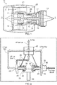
- a ducted fan gas turbine engine incorporating the invention is generally indicated at 10 and has a principal and rotational axis X-X.
- the engine comprises, in axial flow series, an air intake 11, a propulsive fan 12, an intermediate pressure compressor 13, a high-pressure compressor 14, combustion equipment 15, a high-pressure turbine 16, an intermediate pressure turbine 17, a low-pressure turbine 18 and a core engine exhaust nozzle 19.
- a nacelle 21 generally surrounds the engine 10 and defines the intake 11, a bypass duct 22 and a bypass exhaust nozzle 23.
- air entering the intake 11 is accelerated by the fan 12 to produce two air flows: a first air flow A into the intermediate-pressure compressor 13 and a second air flow B which passes through the bypass duct 22 to provide propulsive thrust.
- the intermediate-pressure compressor 13 compresses the air flow A directed into it before delivering that air to the high-pressure compressor 14 where further compression takes place.
- the compressed air exhausted from the high-pressure compressor 14 is directed into the combustion equipment 15 where it is mixed with fuel and the mixture combusted.
- the resultant hot combustion products then expand through, and thereby drive the high, intermediate and low-pressure turbines 16, 17, 18 before being exhausted through the nozzle 19 to provide additional propulsive thrust.
- the high, intermediate and low-pressure turbines respectively drive the high and intermediate-pressure compressors 14, 13 and the fan 12 by suitable interconnecting shafts.
- the engine has a fuel pumping unit (not shown in Figure 1 ) which draws fuel from a fuel tank, and supplies pressurised fuel to a fuel metering unit of the engine. The metered fuel is then sent to the burners of the combustion equipment 15.
- a fuel pumping unit (not shown in Figure 1 ) which draws fuel from a fuel tank, and supplies pressurised fuel to a fuel metering unit of the engine. The metered fuel is then sent to the burners of the combustion equipment 15.
- N s N ⁇ Q ⁇ p ⁇ ⁇ g 0.75
- N pump speed
- Q volume flow rate
- ⁇ p pump pressure rise
- p density
- g acceleration due to gravity.
- US units of specific speed use flow in US Gallons per minute (USGPM), speed in revolutions per minute (RPM), and pressure rise in pounds square inch (psi). These units and flow rates in Imperial Gallons per hour (IGPH) are used in following graphs and the discussion below.
- the first (LP) stage can thus be run at a speed that allows it to meet the low inlet pressure and multiphase flow (V/L) requirements when airframe fuel pumps are inoperative.
- the first stage pump can be arranged to generate the required pressure rise for engine power settings below cruise. For a modern engine with staged combustion this is around 3.45 MPa (500 psi).
- the second (HP) stage is fed with boosted pressure fuel from the first stage and so it can be run at a higher speed, which is desirable for the reduction of its size and weight. This can also increase the specific speed of the second stage, which in turn increases its efficiency.
- the second stage can be sized to generate the balance of the pressure rise required at high engine power levels. For a modern system, with staged combustion, the second stage would be required to generate about 10.34 MPa (1500 psi) at take-off flows. The total pressure rise of the pump unit at take-off would therefore be around 13.79 MPa (2000 psi).
- the pump unit is arranged so that the first and second stages operate at different speeds. In the embodiments of the invention discussed in detail below, this can be achieved with a single input drive shaft from the engine accessory gearbox.
- the efficiency of a two stage pump can still be very low and may result in high fuel temperatures which in turn limit the heat sink capability of the fuel to cool the engine oil.
- Both the pressure rise and input power of a centrifugal pump are proportional to the density of the fluid it is handling.
- the second stage of the pump unit is run "dry" (i.e. runs in air) at low engine power settings. Since the density of air is much less than the density of fuel, this can significantly reduce the power consumption of the second stage.
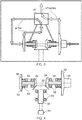
- Figures 2 and 3 show schematically a comparative example of the fuel pumping unit having first stage (LP) and second stage (HP) centrifugal pumps, fuel flows being indicated by thick arrowed lines.
- a drive input 30 from the engine accessory gearbox terminates in a bevel gear 32.
- Further bevel gears 34, 36 at the ends of first stage 38 and second stage 40 impeller shafts mesh with the input bevel gear.
- At the other ends of the impeller shafts are mounted first stage 42 and second stage 44 impellers of respectively the first and second stage centrifugal pumps.
- the first stage can incorporate an axial flow inducer 43.
- the bevel gears 32, 34, 36 form a gear arrangement operatively located between the drive input 30 and the low and high pressure pumps.
- the first stage bevel gear 34 is larger diameter than the second stage bevel gear 36, making the first stage pump run at a slower speed than the second stage pump. More particularly, the first stage pump can be run at a low speed compatible with the low inlet pressure and multiphase flow that occur when the airframe fuel pumps are inoperative, while the second stage can be run at a higher speed to reduce its size and weight and to increase its specific speed thereby improving its peak efficiency.
- a selector valve 46 controls the operational mode of the pumping unit. It also supplies fuel (indicated in Figures 2 and 3 by thin arrowed lines) to fuel lubricated journal bearings 48 on which the impeller shafts 38, 40 are mounted. Back-to-back oil 50 and fuel 52 seals with inter-seal drains are positioned between the bearings and the oil-lubricated bevel gears 34, 36 to prevent mingling of fuel with gear lubrication oil.
- the lubrication oil supply and scavenge can be provided by the accessory gearbox.
- the selector valve 46 has a first position which provides a high power mode, illustrated in Figure 2 . In this mode, the valve directs the delivery flow from the first stage to the inlet of the second stage and then directs the delivery flow from the second stage to a fuel metering unit (FMU) of the engine. In a second position, illustrated in Figure 3 , the selector valve provides a low power mode which directs the flow from the first stage directly to the FMU and shuts off fuel to the second stage so that it runs dry. Accumulator chambers, incorporating suitable baffling, may be provided within the valve to attenuate high transient pressures that may occur when the second stage transitions between running on fuel and air and vice-versa. In both modes, the selector valve also directs flow to the pump bearings 48.
- FMU fuel metering unit
- the selector valve 46 may be actuated electrically or hydraulically either directly from an engine electronic control (EEC) or from the FMU.
- EEC engine electronic control
- FIG. 4 shows schematically optional variant features of the drive and pumps of the fuel pumping unit of the comparative example.
- oil lubricated rolling element bearings 54 can be used to provide axial and radial load support for the bevel gear shaft 30, the shaft 30 being driven from the accessory gearbox via a splined shaft connection 56 at the outside of a housing of the pumping unit.
- the impeller shafts 38, 40 can be provided with axial and radial load support by oil lubricated rolling element bearings 58, with the oil 50 and fuel 52 seals now being positioned between the impellers 42, 44 and the bearings 58.
- the second stage pump may experience high axial loads during the transition from running dry to running with fuel, and hydrostatic axial thrust bearings may be advantageously deployed at this location.
- the accessory gearbox can supply and scavenge the oil used to lubricate the rolling element bearings 54, 58.
- FIG 5 shows schematically another variant of the drive and pumps of the fuel pumping unit of the comparative example in which the impeller shafts 38, 40 of the two pumps are inclined with regard to the centreline. This can be beneficial in respect of the overall space envelope of the unit.
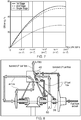
- the maximum speed for the first stage pump is 11200 RPM based on the assumption that an axial inducer would achieve a suction specific speed of 20,000 in US units. Such a drive speed is similar to that for a high performance military first stage centrifugal pump. An impeller diameter of around 160 mm would then generate a pressure rise of about 3.45 MPa (500 psi) at the take-off flow.
- the pump temperature rise was calculated for a cruise condition based on 95% engine speed and a burnt flow of 3.64 kilolitres per hour (800 IGPH) and for an idle condition based on 65% engine speed and a burnt flow of 0.45 kilolitres per hour (100 IGPH).
- the adiabatic temperature rise is predicted to be 9.3°C and at the idle condition around 26°C.
- the two stage centrifugal pumping unit thus addresses a number of issues associated with engine driven centrifugal pumps, namely:
- FIGS 8 to 10 show schematically an embodiment of the fuel pumping unit.
- the pumping unit has a positive displacement start pump 60 that can be mounted on the first stage impeller shaft 38 to provide engine starting/priming capability.
- the selector valve 46 has a third position, illustrated in Figure 8 , which provides a start mode in which the flow output from LP pump is routed to the start pump, and from thence to the FMU and the engine burners at start.
- the first stage pump only generates a very low pressure rise, while in the start mode the second stage pump runs on air to reduce drag and torque.
- the start pump is able to provide an adequate pressure rise for the fuel sent to the FMU.
- the selector valve 46 takes the flow output of the start pump 60 and recirculates it back to the start pump inlet at a lower pressure.
- Figures 9 and 10 show respectively the high and low pressure modes of the unit. Accordingly, at engines speeds at and above ground idle, the start pump operates at a low back pressure and thus introduces only small parasitic losses into the fuel system.
- the start pump 60 also serves to prime the centrifugal pumps. It can be, for example, an external gear, gerotor or vane pump. However, from a size/weight standpoint, a radially balanced (dual lobe) vane pump is particularly advantageous for the following reasons:
Landscapes
- Engineering & Computer Science (AREA)
- Mechanical Engineering (AREA)
- General Engineering & Computer Science (AREA)
- Chemical & Material Sciences (AREA)
- Combustion & Propulsion (AREA)
- Structures Of Non-Positive Displacement Pumps (AREA)
Claims (8)
- Unité de pompage de carburant comportant une pompe centrifuge basse pression (42) et une pompe centrifuge haute pression (44), en utilisation, la pompe centrifuge basse pression fournissant du carburant à une pression renforcée à la pompe centrifuge haute pression pour une alimentation consécutive à une unité de dosage de carburant ;
l'unité de pompage ayant en outre une entrée d'entraînement (30) qui entraîne les pompes centrifuges basse pression (42) et haute pression (44) ;
l'unité de pompage ayant en outre une pompe de démarrage à déplacement positif (60) qui est entraînée par l'entrée d'entraînement ; et
l'unité de pompage ayant en outre une vanne de sélection (46) qui est configurée pour fournir de manière sélectionnable un mode haute pression, un mode basse pression et un mode de démarrage, dans laquelle :en mode haute pression, la pompe centrifuge basse pression (42) alimente la pompe centrifuge haute pression (44) en carburant sous la pression renforcée pour une alimentation consécutive vers l'unité de dosage de carburant ;en mode basse pression, l'alimentation en carburant de la pompe centrifuge basse pression (42) vers la pompe centrifuge haute pression (44) est fermée, de sorte que la pompe centrifuge haute pression (44) est à sec et que la pompe centrifuge basse pression (42) alimente du carburant vers l'unité de dosage de carburant ;en mode de démarrage, la pompe centrifuge basse pression (42) alimente la pompe de démarrage positive (60) en carburant à la pression renforcée pour une alimentation en carburant consécutive de l'unité de dosage de carburant, et l'alimentation en carburant de la pompe centrifuge basse pression (42) vers la pompe centrifuge haute pression (44) est fermée de sorte que la pompe centrifuge haute pression (44) soit à sec ;l'entrée d'entraînement (30) est un arbre d'entraînement d'entrée unique provenant d'une boîte d'engrenages accessoire de moteur, et un agencement d'engrenages est positionné de manière opérationnelle entre l'arbre d'entraînement d'entrée unique et les pompes centrifuges basse pression (42) et haute pression (44), de sorte que les pompes centrifuges basse pression (42) et haute pression (44) sont entraînées à différentes vitesses par l'entrée d'entraînement, et de telle sorte que la pompe de démarrage à déplacement positif (60) est entraînée par l'intermédiaire l'agencement d'engrenages ; dans les modes haute et basse pression, la vanne de sélection (46) fait recirculer le carburant entre la pompe de démarrage à déplacement positif (60) et la vanne de sélection (46). - Unité de pompage de carburant selon la revendication 1, dans laquelle la pompe centrifuge haute pression (44) est entraînée à une vitesse supérieure à la pompe centrifuge basse pression (42).
- Unité de pompage de carburant selon la revendication 1 ou 2, dans laquelle l'agencement d'engrenages comprend un entraînement à engrenage conique.
- Unité de pompage de carburant selon l'une quelconque des revendications précédentes, comportant en outre un inducteur à flux axial au niveau de l'entrée de la pompe centrifuge basse pression (42).
- Unité de pompage de carburant selon l'une quelconque des revendications précédentes, dans laquelle des axes des pompes centrifuges basse pression (42) et haute pression (44) sont inclinés l'un par rapport à l'autre.
- Unité de pompage de carburant selon la revendication 5, dans laquelle la pompe centrifuge basse pression (42) et la pompe de démarrage à déplacement positif (60) sont entraînées à la même vitesse par l'entrée d'entraînement.
- Unité de pompage de carburant selon l'une quelconque des revendications précédentes, apte au pompage de carburant pour un moteur d'aéronef.
- Aéromoteur ayant l'unité de pompage de carburant selon l'une quelconque des revendications précédentes.
Applications Claiming Priority (1)
| Application Number | Priority Date | Filing Date | Title |
|---|---|---|---|
| GBGB1420635.3A GB201420635D0 (en) | 2014-11-20 | 2014-11-20 | Fuel pumping unit |
Publications (2)
| Publication Number | Publication Date |
|---|---|
| EP3023615A1 EP3023615A1 (fr) | 2016-05-25 |
| EP3023615B1 true EP3023615B1 (fr) | 2019-07-03 |
Family
ID=52292265
Family Applications (1)
| Application Number | Title | Priority Date | Filing Date |
|---|---|---|---|
| EP15183775.4A Not-in-force EP3023615B1 (fr) | 2014-11-20 | 2015-09-03 | Unite de pompage de carburant |
Country Status (3)
| Country | Link |
|---|---|
| US (1) | US10138816B2 (fr) |
| EP (1) | EP3023615B1 (fr) |
| GB (1) | GB201420635D0 (fr) |
Families Citing this family (22)
| Publication number | Priority date | Publication date | Assignee | Title |
|---|---|---|---|---|
| CN112177938B (zh) | 2016-08-10 | 2023-05-26 | 可克斯塔特国际股份有限公司 | 模块化多级泵组件 |
| US20180050812A1 (en) * | 2016-08-16 | 2018-02-22 | Hamilton Sundstrand Corporation | Aircraft fuel pump systems |
| US10428816B2 (en) * | 2016-10-24 | 2019-10-01 | Hamilton Sundstrand Corporation | Variable speed multi-stage pump |
| CN107939698A (zh) * | 2017-11-30 | 2018-04-20 | 衢州学院 | 一种新结构多功能复合泵送装置 |
| US10865713B2 (en) * | 2018-07-20 | 2020-12-15 | Hamilton Sundstrand Corporation | Systems and methods for cooling electronic engine control devices |
| US11085636B2 (en) * | 2018-11-02 | 2021-08-10 | General Electric Company | Fuel oxygen conversion unit |
| CN109555714B (zh) * | 2019-01-23 | 2024-07-09 | 英飞同仁风机股份有限公司 | 一种可变双进风离心风机、实现方法及系统 |
| US20200300169A1 (en) * | 2019-03-20 | 2020-09-24 | United Technologies Corporation | Mechanical demand fuel pumping system |
| US11629652B2 (en) | 2020-02-05 | 2023-04-18 | Hamilton Sundstrand Corporation | Metering pump system |
| US11788427B2 (en) | 2021-06-10 | 2023-10-17 | Pratt & Whitney Canada Corp. | Lubricant pump system and method for aircraft engine |
| US12071898B2 (en) * | 2021-07-30 | 2024-08-27 | Hamilton Sundstrand Corporation | Fluid pump systems |
| US11971040B2 (en) * | 2021-10-25 | 2024-04-30 | Hamilton Sundstrand Corporation | Aircraft fuel system with clutched augmentor pump |
| US11828233B2 (en) * | 2021-11-26 | 2023-11-28 | Hamilton Sundstrand Corporation | Fuel pump systems |
| US11725585B2 (en) * | 2021-11-30 | 2023-08-15 | Hamilton Sundstrand Corporation (HSC) | Fuel delivery pump selection |
| US11629643B1 (en) * | 2022-01-07 | 2023-04-18 | Hamilton Sundstrand Corporation | Fuel pump systems |
| FR3132931B1 (fr) * | 2022-02-18 | 2024-01-12 | Safran Aircraft Engines | Système de régulation de carburant |
| US20230417190A1 (en) * | 2022-06-22 | 2023-12-28 | Hamilton Sundstrand Corporation | Dual fuel pump system for an aircraft |
| CN116163987B (zh) * | 2023-02-02 | 2025-07-15 | 长沙中联泵业股份有限公司 | 一种自动调控压力平衡的多级泵 |
| US12209538B1 (en) | 2023-09-11 | 2025-01-28 | Hamilton Sundstrand Corporation | Three pump fuel systems with selectable main and augmentor pumps |
| US12366207B2 (en) | 2023-09-11 | 2025-07-22 | Hamilton Sundstrand Corporation | Variable displacement pump (VDP) systems with dry-out centrifugal main pump |
| US12366206B2 (en) | 2023-09-11 | 2025-07-22 | Hamilton Sundstrand Corporation | Variable displacement pump (VDP) systems with dual dry out pumps |
| US12352211B1 (en) * | 2024-02-28 | 2025-07-08 | Hamilton Sundstrand Corporation | Dual pump electrified fuel system with parallelism |
Family Cites Families (10)
| Publication number | Priority date | Publication date | Assignee | Title |
|---|---|---|---|---|
| GB667022A (en) | 1949-03-10 | 1952-02-20 | Rolls Royce | Improvements relating to gas-turbine engine fuel systems |
| US3147712A (en) * | 1960-09-02 | 1964-09-08 | Gen Motors Corp | Fuel pumping system for gas turbines |
| US3183838A (en) * | 1963-03-27 | 1965-05-18 | Flygts Pumpar Ab | Twin pump device |
| US3547557A (en) | 1968-10-14 | 1970-12-15 | Chandler Evans Inc | Fluid pump and delivery system |
| US3614269A (en) * | 1970-03-09 | 1971-10-19 | Chandler Evans Inc | Integrated pump-control system using a unitized pump |
| DD136761A1 (de) * | 1978-05-29 | 1979-07-25 | Hans Spengler | Hochdruckkreiselpumpenaggregat |
| GB9325029D0 (en) * | 1993-12-07 | 1994-02-02 | Lucas Ind Plc | Pump |
| US6447262B1 (en) * | 1999-05-14 | 2002-09-10 | Argo-Tech Corporation | Pumping system for a multi-stage pump |
| US7845177B2 (en) * | 2004-09-16 | 2010-12-07 | Hamilton Sundstrand Corporation | Metering demand fuel system |
| US9453463B2 (en) * | 2013-01-17 | 2016-09-27 | Honeywell International Inc. | High efficiency, high pressure gas turbine engine fuel supply system |
-
2014
- 2014-11-20 GB GBGB1420635.3A patent/GB201420635D0/en not_active Ceased
-
2015
- 2015-09-03 EP EP15183775.4A patent/EP3023615B1/fr not_active Not-in-force
- 2015-09-18 US US14/858,614 patent/US10138816B2/en active Active
Non-Patent Citations (1)
| Title |
|---|
| None * |
Also Published As
| Publication number | Publication date |
|---|---|
| US10138816B2 (en) | 2018-11-27 |
| EP3023615A1 (fr) | 2016-05-25 |
| GB201420635D0 (en) | 2015-01-07 |
| US20160146108A1 (en) | 2016-05-26 |
Similar Documents
| Publication | Publication Date | Title |
|---|---|---|
| EP3023615B1 (fr) | Unite de pompage de carburant | |
| US11319837B2 (en) | Lubrication systems and methods with superposition gearbox | |
| US11248532B2 (en) | Hybrid electric dual spool power extraction gearbox | |
| US8172512B2 (en) | Accessory gearbox system with compressor driven seal air supply | |
| EP3171055B1 (fr) | Système de lubrification de vitesse proche de zéro pour moteur à turbine | |
| US7418821B2 (en) | Aircraft gas turbine engines | |
| US20160160714A1 (en) | Gas turbine engine with split lubrication system | |
| US20140331639A1 (en) | Turbomachine Lubrication System with an Anti-Siphon Valve for Windmilling | |
| EP1647675B1 (fr) | Alimentation d'huile adéquate pour un système de réservoir d'huile pour un moteur d'aéronef | |
| CN112483276A (zh) | 气体涡轮引擎 | |
| CN104136721B (zh) | 涡轮发动机及其操作方法 | |
| CN116733607A (zh) | 气体涡轮引擎和功率电子设备的组合 | |
| US12540669B2 (en) | Gearbox assembly | |
| EP4116546B1 (fr) | Système de lubrification avec fonction anti-amorçage | |
| US12228077B2 (en) | Fuel system including driving turbine | |
| US12516668B2 (en) | Gear pump assembly | |
| GB2523196A (en) | Gear pump | |
| US20250154904A1 (en) | Fuel control system |
Legal Events
| Date | Code | Title | Description |
|---|---|---|---|
| AK | Designated contracting states |
Kind code of ref document: A1 Designated state(s): AL AT BE BG CH CY CZ DE DK EE ES FI FR GB GR HR HU IE IS IT LI LT LU LV MC MK MT NL NO PL PT RO RS SE SI SK SM TR |
|
| AX | Request for extension of the european patent |
Extension state: BA ME |
|
| PUAI | Public reference made under article 153(3) epc to a published international application that has entered the european phase |
Free format text: ORIGINAL CODE: 0009012 |
|
| STAA | Information on the status of an ep patent application or granted ep patent |
Free format text: STATUS: REQUEST FOR EXAMINATION WAS MADE |
|
| 17P | Request for examination filed |
Effective date: 20161124 |
|
| RBV | Designated contracting states (corrected) |
Designated state(s): AL AT BE BG CH CY CZ DE DK EE ES FI FR GB GR HR HU IE IS IT LI LT LU LV MC MK MT NL NO PL PT RO RS SE SI SK SM TR |
|
| RAP1 | Party data changed (applicant data changed or rights of an application transferred) |
Owner name: ROLLS-ROYCE PLC |
|
| STAA | Information on the status of an ep patent application or granted ep patent |
Free format text: STATUS: EXAMINATION IS IN PROGRESS |
|
| 17Q | First examination report despatched |
Effective date: 20170522 |
|
| GRAP | Despatch of communication of intention to grant a patent |
Free format text: ORIGINAL CODE: EPIDOSNIGR1 |
|
| STAA | Information on the status of an ep patent application or granted ep patent |
Free format text: STATUS: GRANT OF PATENT IS INTENDED |
|
| RIC1 | Information provided on ipc code assigned before grant |
Ipc: F04B 41/06 20060101ALI20190116BHEP Ipc: F04C 2/10 20060101ALN20190116BHEP Ipc: F02C 7/236 20060101AFI20190116BHEP Ipc: F04C 2/34 20060101ALN20190116BHEP Ipc: F04C 11/00 20060101ALN20190116BHEP Ipc: F04D 9/04 20060101ALI20190116BHEP Ipc: F04D 13/12 20060101ALI20190116BHEP |
|
| INTG | Intention to grant announced |
Effective date: 20190213 |
|
| GRAS | Grant fee paid |
Free format text: ORIGINAL CODE: EPIDOSNIGR3 |
|
| GRAA | (expected) grant |
Free format text: ORIGINAL CODE: 0009210 |
|
| STAA | Information on the status of an ep patent application or granted ep patent |
Free format text: STATUS: THE PATENT HAS BEEN GRANTED |
|
| AK | Designated contracting states |
Kind code of ref document: B1 Designated state(s): AL AT BE BG CH CY CZ DE DK EE ES FI FR GB GR HR HU IE IS IT LI LT LU LV MC MK MT NL NO PL PT RO RS SE SI SK SM TR |
|
| REG | Reference to a national code |
Ref country code: GB Ref legal event code: FG4D |
|
| REG | Reference to a national code |
Ref country code: CH Ref legal event code: EP Ref country code: AT Ref legal event code: REF Ref document number: 1151293 Country of ref document: AT Kind code of ref document: T Effective date: 20190715 |
|
| REG | Reference to a national code |
Ref country code: IE Ref legal event code: FG4D |
|
| REG | Reference to a national code |
Ref country code: DE Ref legal event code: R096 Ref document number: 602015033025 Country of ref document: DE |
|
| REG | Reference to a national code |
Ref country code: NL Ref legal event code: MP Effective date: 20190703 |
|
| REG | Reference to a national code |
Ref country code: LT Ref legal event code: MG4D |
|
| REG | Reference to a national code |
Ref country code: AT Ref legal event code: MK05 Ref document number: 1151293 Country of ref document: AT Kind code of ref document: T Effective date: 20190703 |
|
| PG25 | Lapsed in a contracting state [announced via postgrant information from national office to epo] |
Ref country code: FI Free format text: LAPSE BECAUSE OF FAILURE TO SUBMIT A TRANSLATION OF THE DESCRIPTION OR TO PAY THE FEE WITHIN THE PRESCRIBED TIME-LIMIT Effective date: 20190703 Ref country code: LT Free format text: LAPSE BECAUSE OF FAILURE TO SUBMIT A TRANSLATION OF THE DESCRIPTION OR TO PAY THE FEE WITHIN THE PRESCRIBED TIME-LIMIT Effective date: 20190703 Ref country code: PT Free format text: LAPSE BECAUSE OF FAILURE TO SUBMIT A TRANSLATION OF THE DESCRIPTION OR TO PAY THE FEE WITHIN THE PRESCRIBED TIME-LIMIT Effective date: 20191104 Ref country code: HR Free format text: LAPSE BECAUSE OF FAILURE TO SUBMIT A TRANSLATION OF THE DESCRIPTION OR TO PAY THE FEE WITHIN THE PRESCRIBED TIME-LIMIT Effective date: 20190703 Ref country code: CZ Free format text: LAPSE BECAUSE OF FAILURE TO SUBMIT A TRANSLATION OF THE DESCRIPTION OR TO PAY THE FEE WITHIN THE PRESCRIBED TIME-LIMIT Effective date: 20190703 Ref country code: NO Free format text: LAPSE BECAUSE OF FAILURE TO SUBMIT A TRANSLATION OF THE DESCRIPTION OR TO PAY THE FEE WITHIN THE PRESCRIBED TIME-LIMIT Effective date: 20191003 Ref country code: BG Free format text: LAPSE BECAUSE OF FAILURE TO SUBMIT A TRANSLATION OF THE DESCRIPTION OR TO PAY THE FEE WITHIN THE PRESCRIBED TIME-LIMIT Effective date: 20191003 Ref country code: NL Free format text: LAPSE BECAUSE OF FAILURE TO SUBMIT A TRANSLATION OF THE DESCRIPTION OR TO PAY THE FEE WITHIN THE PRESCRIBED TIME-LIMIT Effective date: 20190703 Ref country code: AT Free format text: LAPSE BECAUSE OF FAILURE TO SUBMIT A TRANSLATION OF THE DESCRIPTION OR TO PAY THE FEE WITHIN THE PRESCRIBED TIME-LIMIT Effective date: 20190703 Ref country code: SE Free format text: LAPSE BECAUSE OF FAILURE TO SUBMIT A TRANSLATION OF THE DESCRIPTION OR TO PAY THE FEE WITHIN THE PRESCRIBED TIME-LIMIT Effective date: 20190703 |
|
| RAP2 | Party data changed (patent owner data changed or rights of a patent transferred) |
Owner name: ROLLS-ROYCE PLC |
|
| PG25 | Lapsed in a contracting state [announced via postgrant information from national office to epo] |
Ref country code: IS Free format text: LAPSE BECAUSE OF FAILURE TO SUBMIT A TRANSLATION OF THE DESCRIPTION OR TO PAY THE FEE WITHIN THE PRESCRIBED TIME-LIMIT Effective date: 20191103 Ref country code: GR Free format text: LAPSE BECAUSE OF FAILURE TO SUBMIT A TRANSLATION OF THE DESCRIPTION OR TO PAY THE FEE WITHIN THE PRESCRIBED TIME-LIMIT Effective date: 20191004 Ref country code: ES Free format text: LAPSE BECAUSE OF FAILURE TO SUBMIT A TRANSLATION OF THE DESCRIPTION OR TO PAY THE FEE WITHIN THE PRESCRIBED TIME-LIMIT Effective date: 20190703 Ref country code: RS Free format text: LAPSE BECAUSE OF FAILURE TO SUBMIT A TRANSLATION OF THE DESCRIPTION OR TO PAY THE FEE WITHIN THE PRESCRIBED TIME-LIMIT Effective date: 20190703 Ref country code: LV Free format text: LAPSE BECAUSE OF FAILURE TO SUBMIT A TRANSLATION OF THE DESCRIPTION OR TO PAY THE FEE WITHIN THE PRESCRIBED TIME-LIMIT Effective date: 20190703 Ref country code: AL Free format text: LAPSE BECAUSE OF FAILURE TO SUBMIT A TRANSLATION OF THE DESCRIPTION OR TO PAY THE FEE WITHIN THE PRESCRIBED TIME-LIMIT Effective date: 20190703 |
|
| PG25 | Lapsed in a contracting state [announced via postgrant information from national office to epo] |
Ref country code: TR Free format text: LAPSE BECAUSE OF FAILURE TO SUBMIT A TRANSLATION OF THE DESCRIPTION OR TO PAY THE FEE WITHIN THE PRESCRIBED TIME-LIMIT Effective date: 20190703 |
|
| PG25 | Lapsed in a contracting state [announced via postgrant information from national office to epo] |
Ref country code: IT Free format text: LAPSE BECAUSE OF FAILURE TO SUBMIT A TRANSLATION OF THE DESCRIPTION OR TO PAY THE FEE WITHIN THE PRESCRIBED TIME-LIMIT Effective date: 20190703 Ref country code: DK Free format text: LAPSE BECAUSE OF FAILURE TO SUBMIT A TRANSLATION OF THE DESCRIPTION OR TO PAY THE FEE WITHIN THE PRESCRIBED TIME-LIMIT Effective date: 20190703 Ref country code: RO Free format text: LAPSE BECAUSE OF FAILURE TO SUBMIT A TRANSLATION OF THE DESCRIPTION OR TO PAY THE FEE WITHIN THE PRESCRIBED TIME-LIMIT Effective date: 20190703 Ref country code: EE Free format text: LAPSE BECAUSE OF FAILURE TO SUBMIT A TRANSLATION OF THE DESCRIPTION OR TO PAY THE FEE WITHIN THE PRESCRIBED TIME-LIMIT Effective date: 20190703 Ref country code: PL Free format text: LAPSE BECAUSE OF FAILURE TO SUBMIT A TRANSLATION OF THE DESCRIPTION OR TO PAY THE FEE WITHIN THE PRESCRIBED TIME-LIMIT Effective date: 20190703 |
|
| PG25 | Lapsed in a contracting state [announced via postgrant information from national office to epo] |
Ref country code: SK Free format text: LAPSE BECAUSE OF FAILURE TO SUBMIT A TRANSLATION OF THE DESCRIPTION OR TO PAY THE FEE WITHIN THE PRESCRIBED TIME-LIMIT Effective date: 20190703 Ref country code: SM Free format text: LAPSE BECAUSE OF FAILURE TO SUBMIT A TRANSLATION OF THE DESCRIPTION OR TO PAY THE FEE WITHIN THE PRESCRIBED TIME-LIMIT Effective date: 20190703 Ref country code: MC Free format text: LAPSE BECAUSE OF FAILURE TO SUBMIT A TRANSLATION OF THE DESCRIPTION OR TO PAY THE FEE WITHIN THE PRESCRIBED TIME-LIMIT Effective date: 20190703 Ref country code: IS Free format text: LAPSE BECAUSE OF FAILURE TO SUBMIT A TRANSLATION OF THE DESCRIPTION OR TO PAY THE FEE WITHIN THE PRESCRIBED TIME-LIMIT Effective date: 20200224 |
|
| REG | Reference to a national code |
Ref country code: CH Ref legal event code: PL |
|
| REG | Reference to a national code |
Ref country code: DE Ref legal event code: R097 Ref document number: 602015033025 Country of ref document: DE |
|
| PLBE | No opposition filed within time limit |
Free format text: ORIGINAL CODE: 0009261 |
|
| STAA | Information on the status of an ep patent application or granted ep patent |
Free format text: STATUS: NO OPPOSITION FILED WITHIN TIME LIMIT |
|
| PG2D | Information on lapse in contracting state deleted |
Ref country code: IS |
|
| PG25 | Lapsed in a contracting state [announced via postgrant information from national office to epo] |
Ref country code: IE Free format text: LAPSE BECAUSE OF NON-PAYMENT OF DUE FEES Effective date: 20190903 Ref country code: CH Free format text: LAPSE BECAUSE OF NON-PAYMENT OF DUE FEES Effective date: 20190930 Ref country code: LU Free format text: LAPSE BECAUSE OF NON-PAYMENT OF DUE FEES Effective date: 20190903 Ref country code: LI Free format text: LAPSE BECAUSE OF NON-PAYMENT OF DUE FEES Effective date: 20190930 |
|
| REG | Reference to a national code |
Ref country code: BE Ref legal event code: MM Effective date: 20190930 |
|
| 26N | No opposition filed |
Effective date: 20200603 |
|
| PG25 | Lapsed in a contracting state [announced via postgrant information from national office to epo] |
Ref country code: SI Free format text: LAPSE BECAUSE OF FAILURE TO SUBMIT A TRANSLATION OF THE DESCRIPTION OR TO PAY THE FEE WITHIN THE PRESCRIBED TIME-LIMIT Effective date: 20190703 Ref country code: BE Free format text: LAPSE BECAUSE OF NON-PAYMENT OF DUE FEES Effective date: 20190930 |
|
| PG25 | Lapsed in a contracting state [announced via postgrant information from national office to epo] |
Ref country code: CY Free format text: LAPSE BECAUSE OF FAILURE TO SUBMIT A TRANSLATION OF THE DESCRIPTION OR TO PAY THE FEE WITHIN THE PRESCRIBED TIME-LIMIT Effective date: 20190703 |
|
| PG25 | Lapsed in a contracting state [announced via postgrant information from national office to epo] |
Ref country code: HU Free format text: LAPSE BECAUSE OF FAILURE TO SUBMIT A TRANSLATION OF THE DESCRIPTION OR TO PAY THE FEE WITHIN THE PRESCRIBED TIME-LIMIT; INVALID AB INITIO Effective date: 20150903 Ref country code: MT Free format text: LAPSE BECAUSE OF FAILURE TO SUBMIT A TRANSLATION OF THE DESCRIPTION OR TO PAY THE FEE WITHIN THE PRESCRIBED TIME-LIMIT Effective date: 20190703 |
|
| PG25 | Lapsed in a contracting state [announced via postgrant information from national office to epo] |
Ref country code: MK Free format text: LAPSE BECAUSE OF FAILURE TO SUBMIT A TRANSLATION OF THE DESCRIPTION OR TO PAY THE FEE WITHIN THE PRESCRIBED TIME-LIMIT Effective date: 20190703 |
|
| P01 | Opt-out of the competence of the unified patent court (upc) registered |
Effective date: 20230528 |
|
| PGFP | Annual fee paid to national office [announced via postgrant information from national office to epo] |
Ref country code: GB Payment date: 20230926 Year of fee payment: 9 |
|
| PGFP | Annual fee paid to national office [announced via postgrant information from national office to epo] |
Ref country code: FR Payment date: 20230926 Year of fee payment: 9 Ref country code: DE Payment date: 20230928 Year of fee payment: 9 |
|
| REG | Reference to a national code |
Ref country code: DE Ref legal event code: R119 Ref document number: 602015033025 Country of ref document: DE |
|
| GBPC | Gb: european patent ceased through non-payment of renewal fee |
Effective date: 20240903 |
|
| PG25 | Lapsed in a contracting state [announced via postgrant information from national office to epo] |
Ref country code: DE Free format text: LAPSE BECAUSE OF NON-PAYMENT OF DUE FEES Effective date: 20250401 |
|
| PG25 | Lapsed in a contracting state [announced via postgrant information from national office to epo] |
Ref country code: GB Free format text: LAPSE BECAUSE OF NON-PAYMENT OF DUE FEES Effective date: 20240903 |
|
| PG25 | Lapsed in a contracting state [announced via postgrant information from national office to epo] |
Ref country code: FR Free format text: LAPSE BECAUSE OF NON-PAYMENT OF DUE FEES Effective date: 20240930 |