EP3023627A1 - Injecteur de carburant - Google Patents
Injecteur de carburant Download PDFInfo
- Publication number
- EP3023627A1 EP3023627A1 EP15190399.4A EP15190399A EP3023627A1 EP 3023627 A1 EP3023627 A1 EP 3023627A1 EP 15190399 A EP15190399 A EP 15190399A EP 3023627 A1 EP3023627 A1 EP 3023627A1
- Authority
- EP
- European Patent Office
- Prior art keywords
- region
- fuel injector
- electrode
- sensor element
- fuel
- Prior art date
- Legal status (The legal status is an assumption and is not a legal conclusion. Google has not performed a legal analysis and makes no representation as to the accuracy of the status listed.)
- Granted
Links
Images

Classifications
-
- F—MECHANICAL ENGINEERING; LIGHTING; HEATING; WEAPONS; BLASTING
- F02—COMBUSTION ENGINES; HOT-GAS OR COMBUSTION-PRODUCT ENGINE PLANTS
- F02M—SUPPLYING COMBUSTION ENGINES IN GENERAL WITH COMBUSTIBLE MIXTURES OR CONSTITUENTS THEREOF
- F02M57/00—Fuel-injectors combined or associated with other devices
- F02M57/005—Fuel-injectors combined or associated with other devices the devices being sensors
-
- F—MECHANICAL ENGINEERING; LIGHTING; HEATING; WEAPONS; BLASTING
- F02—COMBUSTION ENGINES; HOT-GAS OR COMBUSTION-PRODUCT ENGINE PLANTS
- F02M—SUPPLYING COMBUSTION ENGINES IN GENERAL WITH COMBUSTIBLE MIXTURES OR CONSTITUENTS THEREOF
- F02M51/00—Fuel-injection apparatus characterised by being operated electrically
- F02M51/005—Arrangement of electrical wires and connections, e.g. wire harness, sockets, plugs; Arrangement of electronic control circuits in or on fuel injection apparatus
-
- G—PHYSICS
- G01—MEASURING; TESTING
- G01L—MEASURING FORCE, STRESS, TORQUE, WORK, MECHANICAL POWER, MECHANICAL EFFICIENCY, OR FLUID PRESSURE
- G01L23/00—Devices or apparatus for measuring or indicating or recording rapid changes, such as oscillations, in the pressure of steam, gas, or liquid; Indicators for determining work or energy of steam, internal-combustion, or other fluid-pressure engines from the condition of the working fluid
- G01L23/08—Devices or apparatus for measuring or indicating or recording rapid changes, such as oscillations, in the pressure of steam, gas, or liquid; Indicators for determining work or energy of steam, internal-combustion, or other fluid-pressure engines from the condition of the working fluid operated electrically
- G01L23/10—Devices or apparatus for measuring or indicating or recording rapid changes, such as oscillations, in the pressure of steam, gas, or liquid; Indicators for determining work or energy of steam, internal-combustion, or other fluid-pressure engines from the condition of the working fluid operated electrically by pressure-sensitive members of the piezoelectric type
-
- G—PHYSICS
- G01—MEASURING; TESTING
- G01L—MEASURING FORCE, STRESS, TORQUE, WORK, MECHANICAL POWER, MECHANICAL EFFICIENCY, OR FLUID PRESSURE
- G01L9/00—Measuring steady of quasi-steady pressure of fluid or fluent solid material by electric or magnetic pressure-sensitive elements; Transmitting or indicating the displacement of mechanical pressure-sensitive elements, used to measure the steady or quasi-steady pressure of a fluid or fluent solid material, by electric or magnetic means
- G01L9/0041—Transmitting or indicating the displacement of flexible diaphragms
- G01L9/008—Transmitting or indicating the displacement of flexible diaphragms using piezoelectric devices
-
- F—MECHANICAL ENGINEERING; LIGHTING; HEATING; WEAPONS; BLASTING
- F02—COMBUSTION ENGINES; HOT-GAS OR COMBUSTION-PRODUCT ENGINE PLANTS
- F02M—SUPPLYING COMBUSTION ENGINES IN GENERAL WITH COMBUSTIBLE MIXTURES OR CONSTITUENTS THEREOF
- F02M2200/00—Details of fuel-injection apparatus, not otherwise provided for
- F02M2200/24—Fuel-injection apparatus with sensors
- F02M2200/247—Pressure sensors
-
- F—MECHANICAL ENGINEERING; LIGHTING; HEATING; WEAPONS; BLASTING
- F02—COMBUSTION ENGINES; HOT-GAS OR COMBUSTION-PRODUCT ENGINE PLANTS
- F02M—SUPPLYING COMBUSTION ENGINES IN GENERAL WITH COMBUSTIBLE MIXTURES OR CONSTITUENTS THEREOF
- F02M2200/00—Details of fuel-injection apparatus, not otherwise provided for
- F02M2200/80—Fuel injection apparatus manufacture, repair or assembly
- F02M2200/8038—Fuel injection apparatus manufacture, repair or assembly the assembly involving use of adhesives, glue or the like
Definitions
- the invention relates to a fuel injector, in particular a common rail injector.
- a fuel injector which has a measuring device in the region of an injector or a holding body, which serves to detect the position of a nozzle needle designed as an injection member, in particular their closing time.
- This should, in particular over the operating life of the fuel injector considered due to wear or other circumstances always optimal adjustment of the control of the fuel injector can be achieved so that an internal combustion engine, for example, can always achieve optimum exhaust emissions.
- a designed as a piezoelectric element sensor element is glued to the surface of the injector.
- the location of the piezoelectric element is in the immediate vicinity of a high-pressure space of the fuel injector with fuel under high pressure supply bore, in the region of the wall thickness of the injector is reduced. As a result, a deformation region is formed, which bulges more elastically outward, the greater the fuel pressure in the supply bore.
- expansions or tensile stresses are generated via the piezoelectric element glued in the area of the deformation region and transmitted via the adhesive layer into the piezoelement, which leads to a corresponding voltage signal of the piezoelectric element which can be evaluated by means of an evaluation circuit in order thereby to check the fuel pressure to close in the supply bore and thereby on the closing and opening time of the nozzle needle. Details regarding the design of the piezoelectric element, in particular with regard to the arrangement of the two electrodes of the piezoelectric element and their electrical contacting are not apparent from the mentioned document.
- the invention has the object, a fuel injector, in particular a common rail injector, such form that a maximum resolution or a maximum sensor signal of the piezoelectric element can be achieved, the size of the piezoelectric element to be minimized should.
- a fuel injector in particular a common rail injector, such form that a maximum resolution or a maximum sensor signal of the piezoelectric element can be achieved, the size of the piezoelectric element to be minimized should.
- a relatively small recess is required for receiving the piezoelement on the fuel injector.
- a fuel injector with the features of claim 1 essentially by the fact that the two electrodes of the piezoelectric element are arranged on the side facing away from the fuel injector side of the piezoelectric element in partial overlap, wherein in the overlap region of the two electrodes, the two electrodes at least partially , are preferably arranged completely electrically isolated from each other.
- the advantage is achieved that the maximum ceramic or electrode surface is available for generating a stress due to an expansion in the piezoelectric element.
- the size of the piezoelectric element is minimized in terms of the required base area in that the fuel injector facing electrode protrudes laterally at least substantially not over the base of the ceramic of the piezoelectric element by the overlap with the other electrode. It is only necessary to extend the electrode facing the fuel injector by means of an intermediate or connecting portion in the direction of the other electrode and there to deform or bend over against the other electrode to form the overlap region with the other electrode.
- the two electrodes are arranged on the side facing away from the deformation region of the sensor element at least substantially parallel to each other, and that the overlap region is a partial surface of the surface of the second electrode.
- an insulation element is arranged between the two electrodes in the overlapping area.
- the insulating element can either be a separate component or element, or it can be an element which is an integral part of one of the two electrodes and is formed, for example, by a coating.
- the second electrode on the The deformation region or injector side facing away from the sensor element is arranged at least almost completely over the entire surface in operative connection with the insulating element.
- the insulation element has a recess for electrical contacting of the second electrode in a region arranged outside the covering region ,
- the insulation element is designed in the form of a coating.
- a relatively thin insulation element can be achieved, so that the overall height of the sensor element is at least essentially not increased compared with the prior art, and secondly, the attachment or positioning of an insulation element during installation is unnecessary, if this is provided as a separate or separate element Loose part would be formed, and would have to be connected for example via an adhesive bond with the electrodes.
- connection point between the deformation region and the sensor element can be arranged in a region relatively distant from the combustion chamber.
- lower temperatures prevail during operation of the internal combustion engine than in a region of the injector housing which is close to the combustion chamber.
- the connection between the addressed components thermally relatively little claimed.
- a structural design of the deformation region in the region of a blind-hole-shaped depression or a flattening of the injector housing is preferred. Both variants can manufacture particularly simple and accurate manufacture and also allow in a relatively simple manner the formation of a flat surface for connection of the sensor element.
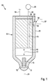
- the Indian Fig. 1 fuel injector 10 shown greatly simplified is designed as a so-called common rail injector, and is used to inject fuel into the combustion chamber, not shown, of an internal combustion engine, in particular a self-igniting internal combustion engine.
- the fuel injector 10 has an essentially made of metal, possibly multi-part design injector housing 11, in which on the combustion chamber of the internal combustion engine side facing at least one, preferably a plurality of injection openings 12 are arranged for injecting the fuel.
- this forms a high pressure chamber 15, in which a nozzle needle 16 serving as an injection member is arranged in a liftable manner in the direction of the double arrow 17.
- a nozzle needle 16 serving as an injection member is arranged in a liftable manner in the direction of the double arrow 17.
- this forms together with the inner wall of the high-pressure chamber 15 and the injector 11 a sealing seat, so that the injection openings 12 are at least indirectly closed, such that the injection of fuel from the high-pressure chamber 15 in the Combustion chamber of the internal combustion engine is avoided.
- the nozzle needle 16 In the other, not shown, lifted from the sealing seat position of the nozzle needle 16, this releases the injection openings 12 for injecting the fuel into the combustion chamber of the internal combustion engine.
- the movement of the nozzle needle 16, in particular for releasing the injection openings 12, takes place in a manner known per se by means of an actuator, not shown, which can be actuated via a voltage supply line 18 by a control device of the internal combustion engine.
- the actuator may in particular be a magnetic actuator or else a piezoactuator.
- the supply bore 19 is also connected via a fuel connection, not shown, with a fuel line 22, which in turn is coupled to a fuel reservoir 25 (rail).
- axially relatively far-spaced portion of the injector 11 is in the outer wall 23 by way of example a blind hole-shaped recess 24 (FIG. Fig. 1 and 3 ), so that the wall thickness of the injector housing 11 is reduced in the region of the recess 24.
- the injector housing 11 may also have a flattening, in the region of which the wall thickness of the injector housing 11 is reduced.
- the flat bottom 26 of the recess 24 forms part of a deformation region 27.
- the injector 11 is arranged for example in operative connection with a branch 28, which in turn opens into the supply hole 19.
- the fuel pressure currently prevailing in the supply bore 19 also acts in the injector housing 11 on the side facing away from the recess 24.
- the wall section 29 of the injector housing 11 acts on the recess 24 facing side as a deformation region 27 in the manner of an elastically deformable membrane, wherein the deformation, which forms as a curvature, the higher the instantaneous fuel pressure in the supply bore 19 or the branch 28 is, the greater.
- the fuel injector 10 has a measuring device 30.
- the measuring device 30 comprises a sensor element 32 designed as a piezo element 31.
- the piezoelectric element 31 is connected to the deformation region 27 via a material connection in the form of an adhesive connection 34.
- the cross section of the piezoelectric element 31 is at least substantially circular or round.
- the piezo element 31 has at its two opposite end faces in each case an electrode 35, 36, wherein the deformation region 27 facing electrode 35 acts as a cathode example and is connected via the adhesive joint 34 with the deformation region 27.
- a disk 37 made of ceramic material is arranged between the two electrodes 35, 36.
- the two electrodes 35, 36 each cover the entire end face of the piezoelectric element 31 and the ceramic disc 37.
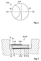
- the deformation region 27 facing electrode 35 is formed on one side over the cross section of the disc 37 on one side extended and a vertical to the deformation region 27 arranged intermediate portion 38 against the top of the second electrode 36 by means of a Maisierabitess 39 by a deformation process such as bending folded.
- an overlapping area 40 which is a partial area of the second electrode 36, with the contacting portion 39 of the first electrode 35 and the second electrode 36 being arranged in the overlapping area 40 in parallel with each other.
- an insulation element 45 is arranged in the covering region 40 of the two electrodes 35, 36 and covers the covering region 40 at least partially, preferably completely.
- the insulating element 45 which electrically isolates or separates the two electrodes 35, 36 from one another, can be a separate component made of an electrically nonconductive material, or else an electrically non-conductive coating which is disposed on one of the two electrodes 35, 36, at least in the covering area 40, is applied.
- the insulating member 45 is formed in the form of a coating 46, in such a way that the coating 46 is applied to the second electrode 36 in approximately semicircular.
- the coating 46 is not only arranged in the covering region 40, but also on both sides of the rounding contacting section 39 of the electrode 35.
- the electrical contacting of the two electrodes 35, 36 takes place on the one hand via the contact section 39 of the electrode 35, and on the other hand in the Area of the electrode 36, in which no coating 46 is provided.
- the electrical contacting can be done for example by welded, soldered or bonded wires, or by spring contacts. Since this is known from the prior art per se and not essential to the invention, this is not shown in the figures.
- the piezoelectric element 31 a differs from the piezoelectric element 31 in that the coating 46 a is applied over the entire surface of the second electrode 36, with the exception of an exemplary circular recess 47 for electrical contacting of the second electrode 36.
- the deformation region 27 elastically deforms outward as a function of the fuel pressure prevailing in the supply bore 19. This deformation is transmitted via the adhesive joint 34 to the piezoelectric element 31, 31 a and there generates depending on the deformation or the tensile stresses electrical voltages that can be used by means of a suitable evaluation circuit, at least indirectly to a position of the nozzle needle 16 in the injector 11 close.
- the fuel injector 10 described so far can be modified or modified in many different ways without deviating from the idea of the invention, in particular the shape or structure of the piezoelectric element 31, 31a may deviate from the illustrated embodiments.
- a Insulation element 45 is arranged, which serves that the entire surface of the two electrodes 35, 36 of the detection of the deformations of the deformation region 27 can serve.
- the insulation element 45 or the coating 46, 46a is arranged or formed only in a partial region of the covering region 40.
Landscapes
- Engineering & Computer Science (AREA)
- Chemical & Material Sciences (AREA)
- Combustion & Propulsion (AREA)
- Mechanical Engineering (AREA)
- General Engineering & Computer Science (AREA)
- Physics & Mathematics (AREA)
- General Physics & Mathematics (AREA)
- Analytical Chemistry (AREA)
- Fuel-Injection Apparatus (AREA)
Applications Claiming Priority (1)
| Application Number | Priority Date | Filing Date | Title |
|---|---|---|---|
| DE102014223775.0A DE102014223775A1 (de) | 2014-11-21 | 2014-11-21 | Kraftstoffinjektor |
Publications (2)
| Publication Number | Publication Date |
|---|---|
| EP3023627A1 true EP3023627A1 (fr) | 2016-05-25 |
| EP3023627B1 EP3023627B1 (fr) | 2021-05-12 |
Family
ID=54329475
Family Applications (1)
| Application Number | Title | Priority Date | Filing Date |
|---|---|---|---|
| EP15190399.4A Active EP3023627B1 (fr) | 2014-11-21 | 2015-10-19 | Injecteur de carburant |
Country Status (2)
| Country | Link |
|---|---|
| EP (1) | EP3023627B1 (fr) |
| DE (1) | DE102014223775A1 (fr) |
Cited By (2)
| Publication number | Priority date | Publication date | Assignee | Title |
|---|---|---|---|---|
| CN111980886A (zh) * | 2020-09-21 | 2020-11-24 | 常州威图流体科技有限公司 | 一种压电微泵支承结构及气体控制装置 |
| CN115780121A (zh) * | 2022-11-10 | 2023-03-14 | 南通山剑防腐科技有限公司 | 一种自动进料的防腐喷涂用喷射装置 |
Citations (5)
| Publication number | Priority date | Publication date | Assignee | Title |
|---|---|---|---|---|
| DE1648582A1 (de) * | 1966-07-12 | 1971-04-01 | List Hans | Piezoelektrischer Messwandler |
| US4672839A (en) * | 1984-11-27 | 1987-06-16 | Ngk Spark Plug Co., Ltd. | Vibration sensor |
| EP2105602A2 (fr) * | 2008-03-28 | 2009-09-30 | Denso Corporation | Capteur de pression de carburant/assemblage de capteur, appareil d'injection de carburant, et appareil de détection de pression |
| DE102012221084A1 (de) * | 2012-11-19 | 2014-05-22 | Robert Bosch Gmbh | Drucksensor und Komponente einer Brennstoffeinspritzanlage mit einem Drucksensor |
| EP2821766A1 (fr) * | 2013-06-18 | 2015-01-07 | Robert Bosch Gmbh | Dispositif de détection |
Family Cites Families (1)
| Publication number | Priority date | Publication date | Assignee | Title |
|---|---|---|---|---|
| DE102014209330A1 (de) | 2014-05-16 | 2015-11-19 | Robert Bosch Gmbh | Vorrichtung zur Erfassung des Kraftstoffdrucks für einen Kraftstoffinjektor, Kraftstoffinjektor sowie Kraftstoffzuführleitung zu einem Kraftstoffinjektor |
-
2014
- 2014-11-21 DE DE102014223775.0A patent/DE102014223775A1/de not_active Withdrawn
-
2015
- 2015-10-19 EP EP15190399.4A patent/EP3023627B1/fr active Active
Patent Citations (5)
| Publication number | Priority date | Publication date | Assignee | Title |
|---|---|---|---|---|
| DE1648582A1 (de) * | 1966-07-12 | 1971-04-01 | List Hans | Piezoelektrischer Messwandler |
| US4672839A (en) * | 1984-11-27 | 1987-06-16 | Ngk Spark Plug Co., Ltd. | Vibration sensor |
| EP2105602A2 (fr) * | 2008-03-28 | 2009-09-30 | Denso Corporation | Capteur de pression de carburant/assemblage de capteur, appareil d'injection de carburant, et appareil de détection de pression |
| DE102012221084A1 (de) * | 2012-11-19 | 2014-05-22 | Robert Bosch Gmbh | Drucksensor und Komponente einer Brennstoffeinspritzanlage mit einem Drucksensor |
| EP2821766A1 (fr) * | 2013-06-18 | 2015-01-07 | Robert Bosch Gmbh | Dispositif de détection |
Cited By (2)
| Publication number | Priority date | Publication date | Assignee | Title |
|---|---|---|---|---|
| CN111980886A (zh) * | 2020-09-21 | 2020-11-24 | 常州威图流体科技有限公司 | 一种压电微泵支承结构及气体控制装置 |
| CN115780121A (zh) * | 2022-11-10 | 2023-03-14 | 南通山剑防腐科技有限公司 | 一种自动进料的防腐喷涂用喷射装置 |
Also Published As
| Publication number | Publication date |
|---|---|
| EP3023627B1 (fr) | 2021-05-12 |
| DE102014223775A1 (de) | 2016-05-25 |
Similar Documents
| Publication | Publication Date | Title |
|---|---|---|
| EP3018337B1 (fr) | Injecteur de carburant | |
| EP3076002B1 (fr) | Injecteur de carburant | |
| EP3023627B1 (fr) | Injecteur de carburant | |
| EP3088729B1 (fr) | Injecteur de carburant et dispositif et procede de montage d'un dispositif de mesure | |
| EP3179090B1 (fr) | Injecteur de carburant | |
| EP3018336B1 (fr) | Injecteur de carburant | |
| EP3088723B1 (fr) | Injecteur de carburant | |
| EP3023758B1 (fr) | Injecteur de carburant | |
| DE102015211186A1 (de) | Kraftstoffinjektor | |
| EP3908743B1 (fr) | Injecteur de carburant | |
| EP3026253B1 (fr) | Injecteur de carburant | |
| EP3076005B1 (fr) | Injecteur de carburant et procédé de fabrication d'un injecteur de carburant | |
| EP3056724A1 (fr) | Injecteur de carburant et procede de fabrication d'un element piezoelectrique pour un injecteur de carburant | |
| DE102018208318A1 (de) | Kraftstoffinjektor | |
| EP3159533B1 (fr) | Injecteur de carburant | |
| EP3176556B1 (fr) | Dispositif de détection et injecteur de carburant comprenant un dispositif de détection | |
| EP3018338A1 (fr) | Injecteur de carburant et procede de fabrication d'un injecteur de carburant | |
| EP3109453A1 (fr) | Injecteur de carburant | |
| EP3181890A1 (fr) | Dispositif de détection et injecteur de carburant comprenant un dispositif de détection | |
| EP3088724A1 (fr) | Injecteur de carburant | |
| EP3112662A1 (fr) | Injecteur de carburant | |
| DE102015224683A1 (de) | Kraftstoffinjektor |
Legal Events
| Date | Code | Title | Description |
|---|---|---|---|
| AK | Designated contracting states |
Kind code of ref document: A1 Designated state(s): AL AT BE BG CH CY CZ DE DK EE ES FI FR GB GR HR HU IE IS IT LI LT LU LV MC MK MT NL NO PL PT RO RS SE SI SK SM TR |
|
| AX | Request for extension of the european patent |
Extension state: BA ME |
|
| PUAI | Public reference made under article 153(3) epc to a published international application that has entered the european phase |
Free format text: ORIGINAL CODE: 0009012 |
|
| STAA | Information on the status of an ep patent application or granted ep patent |
Free format text: STATUS: REQUEST FOR EXAMINATION WAS MADE |
|
| 17P | Request for examination filed |
Effective date: 20161125 |
|
| RBV | Designated contracting states (corrected) |
Designated state(s): AL AT BE BG CH CY CZ DE DK EE ES FI FR GB GR HR HU IE IS IT LI LT LU LV MC MK MT NL NO PL PT RO RS SE SI SK SM TR |
|
| STAA | Information on the status of an ep patent application or granted ep patent |
Free format text: STATUS: EXAMINATION IS IN PROGRESS |
|
| 17Q | First examination report despatched |
Effective date: 20180601 |
|
| RAP1 | Party data changed (applicant data changed or rights of an application transferred) |
Owner name: ROBERT BOSCH GMBH |
|
| GRAP | Despatch of communication of intention to grant a patent |
Free format text: ORIGINAL CODE: EPIDOSNIGR1 |
|
| STAA | Information on the status of an ep patent application or granted ep patent |
Free format text: STATUS: GRANT OF PATENT IS INTENDED |
|
| INTG | Intention to grant announced |
Effective date: 20210113 |
|
| GRAS | Grant fee paid |
Free format text: ORIGINAL CODE: EPIDOSNIGR3 |
|
| GRAA | (expected) grant |
Free format text: ORIGINAL CODE: 0009210 |
|
| STAA | Information on the status of an ep patent application or granted ep patent |
Free format text: STATUS: THE PATENT HAS BEEN GRANTED |
|
| AK | Designated contracting states |
Kind code of ref document: B1 Designated state(s): AL AT BE BG CH CY CZ DE DK EE ES FI FR GB GR HR HU IE IS IT LI LT LU LV MC MK MT NL NO PL PT RO RS SE SI SK SM TR |
|
| REG | Reference to a national code |
Ref country code: GB Ref legal event code: FG4D Free format text: NOT ENGLISH |
|
| REG | Reference to a national code |
Ref country code: CH Ref legal event code: EP |
|
| REG | Reference to a national code |
Ref country code: DE Ref legal event code: R096 Ref document number: 502015014704 Country of ref document: DE |
|
| REG | Reference to a national code |
Ref country code: IE Ref legal event code: FG4D Free format text: LANGUAGE OF EP DOCUMENT: GERMAN |
|
| REG | Reference to a national code |
Ref country code: AT Ref legal event code: REF Ref document number: 1392336 Country of ref document: AT Kind code of ref document: T Effective date: 20210615 |
|
| REG | Reference to a national code |
Ref country code: LT Ref legal event code: MG9D |
|
| REG | Reference to a national code |
Ref country code: NL Ref legal event code: MP Effective date: 20210512 |
|
| PG25 | Lapsed in a contracting state [announced via postgrant information from national office to epo] |
Ref country code: HR Free format text: LAPSE BECAUSE OF FAILURE TO SUBMIT A TRANSLATION OF THE DESCRIPTION OR TO PAY THE FEE WITHIN THE PRESCRIBED TIME-LIMIT Effective date: 20210512 Ref country code: BG Free format text: LAPSE BECAUSE OF FAILURE TO SUBMIT A TRANSLATION OF THE DESCRIPTION OR TO PAY THE FEE WITHIN THE PRESCRIBED TIME-LIMIT Effective date: 20210812 Ref country code: FI Free format text: LAPSE BECAUSE OF FAILURE TO SUBMIT A TRANSLATION OF THE DESCRIPTION OR TO PAY THE FEE WITHIN THE PRESCRIBED TIME-LIMIT Effective date: 20210512 Ref country code: LT Free format text: LAPSE BECAUSE OF FAILURE TO SUBMIT A TRANSLATION OF THE DESCRIPTION OR TO PAY THE FEE WITHIN THE PRESCRIBED TIME-LIMIT Effective date: 20210512 |
|
| PG25 | Lapsed in a contracting state [announced via postgrant information from national office to epo] |
Ref country code: GR Free format text: LAPSE BECAUSE OF FAILURE TO SUBMIT A TRANSLATION OF THE DESCRIPTION OR TO PAY THE FEE WITHIN THE PRESCRIBED TIME-LIMIT Effective date: 20210813 Ref country code: IS Free format text: LAPSE BECAUSE OF FAILURE TO SUBMIT A TRANSLATION OF THE DESCRIPTION OR TO PAY THE FEE WITHIN THE PRESCRIBED TIME-LIMIT Effective date: 20210912 Ref country code: LV Free format text: LAPSE BECAUSE OF FAILURE TO SUBMIT A TRANSLATION OF THE DESCRIPTION OR TO PAY THE FEE WITHIN THE PRESCRIBED TIME-LIMIT Effective date: 20210512 Ref country code: PT Free format text: LAPSE BECAUSE OF FAILURE TO SUBMIT A TRANSLATION OF THE DESCRIPTION OR TO PAY THE FEE WITHIN THE PRESCRIBED TIME-LIMIT Effective date: 20210913 Ref country code: PL Free format text: LAPSE BECAUSE OF FAILURE TO SUBMIT A TRANSLATION OF THE DESCRIPTION OR TO PAY THE FEE WITHIN THE PRESCRIBED TIME-LIMIT Effective date: 20210512 Ref country code: NO Free format text: LAPSE BECAUSE OF FAILURE TO SUBMIT A TRANSLATION OF THE DESCRIPTION OR TO PAY THE FEE WITHIN THE PRESCRIBED TIME-LIMIT Effective date: 20210812 Ref country code: ES Free format text: LAPSE BECAUSE OF FAILURE TO SUBMIT A TRANSLATION OF THE DESCRIPTION OR TO PAY THE FEE WITHIN THE PRESCRIBED TIME-LIMIT Effective date: 20210512 Ref country code: SE Free format text: LAPSE BECAUSE OF FAILURE TO SUBMIT A TRANSLATION OF THE DESCRIPTION OR TO PAY THE FEE WITHIN THE PRESCRIBED TIME-LIMIT Effective date: 20210512 Ref country code: RS Free format text: LAPSE BECAUSE OF FAILURE TO SUBMIT A TRANSLATION OF THE DESCRIPTION OR TO PAY THE FEE WITHIN THE PRESCRIBED TIME-LIMIT Effective date: 20210512 |
|
| PG25 | Lapsed in a contracting state [announced via postgrant information from national office to epo] |
Ref country code: NL Free format text: LAPSE BECAUSE OF FAILURE TO SUBMIT A TRANSLATION OF THE DESCRIPTION OR TO PAY THE FEE WITHIN THE PRESCRIBED TIME-LIMIT Effective date: 20210512 |
|
| PG25 | Lapsed in a contracting state [announced via postgrant information from national office to epo] |
Ref country code: RO Free format text: LAPSE BECAUSE OF FAILURE TO SUBMIT A TRANSLATION OF THE DESCRIPTION OR TO PAY THE FEE WITHIN THE PRESCRIBED TIME-LIMIT Effective date: 20210512 Ref country code: SK Free format text: LAPSE BECAUSE OF FAILURE TO SUBMIT A TRANSLATION OF THE DESCRIPTION OR TO PAY THE FEE WITHIN THE PRESCRIBED TIME-LIMIT Effective date: 20210512 Ref country code: SM Free format text: LAPSE BECAUSE OF FAILURE TO SUBMIT A TRANSLATION OF THE DESCRIPTION OR TO PAY THE FEE WITHIN THE PRESCRIBED TIME-LIMIT Effective date: 20210512 Ref country code: CZ Free format text: LAPSE BECAUSE OF FAILURE TO SUBMIT A TRANSLATION OF THE DESCRIPTION OR TO PAY THE FEE WITHIN THE PRESCRIBED TIME-LIMIT Effective date: 20210512 Ref country code: EE Free format text: LAPSE BECAUSE OF FAILURE TO SUBMIT A TRANSLATION OF THE DESCRIPTION OR TO PAY THE FEE WITHIN THE PRESCRIBED TIME-LIMIT Effective date: 20210512 Ref country code: DK Free format text: LAPSE BECAUSE OF FAILURE TO SUBMIT A TRANSLATION OF THE DESCRIPTION OR TO PAY THE FEE WITHIN THE PRESCRIBED TIME-LIMIT Effective date: 20210512 |
|
| REG | Reference to a national code |
Ref country code: DE Ref legal event code: R097 Ref document number: 502015014704 Country of ref document: DE |
|
| PLBE | No opposition filed within time limit |
Free format text: ORIGINAL CODE: 0009261 |
|
| STAA | Information on the status of an ep patent application or granted ep patent |
Free format text: STATUS: NO OPPOSITION FILED WITHIN TIME LIMIT |
|
| 26N | No opposition filed |
Effective date: 20220215 |
|
| REG | Reference to a national code |
Ref country code: CH Ref legal event code: PL |
|
| PG25 | Lapsed in a contracting state [announced via postgrant information from national office to epo] |
Ref country code: IS Free format text: LAPSE BECAUSE OF FAILURE TO SUBMIT A TRANSLATION OF THE DESCRIPTION OR TO PAY THE FEE WITHIN THE PRESCRIBED TIME-LIMIT Effective date: 20210912 Ref country code: AL Free format text: LAPSE BECAUSE OF FAILURE TO SUBMIT A TRANSLATION OF THE DESCRIPTION OR TO PAY THE FEE WITHIN THE PRESCRIBED TIME-LIMIT Effective date: 20210512 |
|
| REG | Reference to a national code |
Ref country code: BE Ref legal event code: MM Effective date: 20211031 |
|
| GBPC | Gb: european patent ceased through non-payment of renewal fee |
Effective date: 20211019 |
|
| PG25 | Lapsed in a contracting state [announced via postgrant information from national office to epo] |
Ref country code: MC Free format text: LAPSE BECAUSE OF FAILURE TO SUBMIT A TRANSLATION OF THE DESCRIPTION OR TO PAY THE FEE WITHIN THE PRESCRIBED TIME-LIMIT Effective date: 20210512 |
|
| PG25 | Lapsed in a contracting state [announced via postgrant information from national office to epo] |
Ref country code: LU Free format text: LAPSE BECAUSE OF NON-PAYMENT OF DUE FEES Effective date: 20211019 Ref country code: GB Free format text: LAPSE BECAUSE OF NON-PAYMENT OF DUE FEES Effective date: 20211019 Ref country code: BE Free format text: LAPSE BECAUSE OF NON-PAYMENT OF DUE FEES Effective date: 20211031 |
|
| PG25 | Lapsed in a contracting state [announced via postgrant information from national office to epo] |
Ref country code: LI Free format text: LAPSE BECAUSE OF NON-PAYMENT OF DUE FEES Effective date: 20211031 Ref country code: CH Free format text: LAPSE BECAUSE OF NON-PAYMENT OF DUE FEES Effective date: 20211031 |
|
| PG25 | Lapsed in a contracting state [announced via postgrant information from national office to epo] |
Ref country code: IE Free format text: LAPSE BECAUSE OF NON-PAYMENT OF DUE FEES Effective date: 20211019 |
|
| REG | Reference to a national code |
Ref country code: AT Ref legal event code: MM01 Ref document number: 1392336 Country of ref document: AT Kind code of ref document: T Effective date: 20211019 |
|
| PGFP | Annual fee paid to national office [announced via postgrant information from national office to epo] |
Ref country code: FR Payment date: 20221020 Year of fee payment: 8 |
|
| PG25 | Lapsed in a contracting state [announced via postgrant information from national office to epo] |
Ref country code: AT Free format text: LAPSE BECAUSE OF NON-PAYMENT OF DUE FEES Effective date: 20211019 |
|
| PGFP | Annual fee paid to national office [announced via postgrant information from national office to epo] |
Ref country code: IT Payment date: 20221031 Year of fee payment: 8 |
|
| PG25 | Lapsed in a contracting state [announced via postgrant information from national office to epo] |
Ref country code: HU Free format text: LAPSE BECAUSE OF FAILURE TO SUBMIT A TRANSLATION OF THE DESCRIPTION OR TO PAY THE FEE WITHIN THE PRESCRIBED TIME-LIMIT; INVALID AB INITIO Effective date: 20151019 |
|
| PG25 | Lapsed in a contracting state [announced via postgrant information from national office to epo] |
Ref country code: CY Free format text: LAPSE BECAUSE OF FAILURE TO SUBMIT A TRANSLATION OF THE DESCRIPTION OR TO PAY THE FEE WITHIN THE PRESCRIBED TIME-LIMIT Effective date: 20210512 |
|
| PG25 | Lapsed in a contracting state [announced via postgrant information from national office to epo] |
Ref country code: MK Free format text: LAPSE BECAUSE OF FAILURE TO SUBMIT A TRANSLATION OF THE DESCRIPTION OR TO PAY THE FEE WITHIN THE PRESCRIBED TIME-LIMIT Effective date: 20210512 |
|
| PG25 | Lapsed in a contracting state [announced via postgrant information from national office to epo] |
Ref country code: TR Free format text: LAPSE BECAUSE OF FAILURE TO SUBMIT A TRANSLATION OF THE DESCRIPTION OR TO PAY THE FEE WITHIN THE PRESCRIBED TIME-LIMIT Effective date: 20210512 |
|
| PG25 | Lapsed in a contracting state [announced via postgrant information from national office to epo] |
Ref country code: FR Free format text: LAPSE BECAUSE OF NON-PAYMENT OF DUE FEES Effective date: 20231031 |
|
| PG25 | Lapsed in a contracting state [announced via postgrant information from national office to epo] |
Ref country code: MT Free format text: LAPSE BECAUSE OF FAILURE TO SUBMIT A TRANSLATION OF THE DESCRIPTION OR TO PAY THE FEE WITHIN THE PRESCRIBED TIME-LIMIT Effective date: 20210512 |
|
| PG25 | Lapsed in a contracting state [announced via postgrant information from national office to epo] |
Ref country code: IT Free format text: LAPSE BECAUSE OF NON-PAYMENT OF DUE FEES Effective date: 20231019 |
|
| PG25 | Lapsed in a contracting state [announced via postgrant information from national office to epo] |
Ref country code: IT Free format text: LAPSE BECAUSE OF NON-PAYMENT OF DUE FEES Effective date: 20231019 |
|
| PGFP | Annual fee paid to national office [announced via postgrant information from national office to epo] |
Ref country code: DE Payment date: 20251209 Year of fee payment: 11 |