EP3023629A1 - Seilzugstarter - Google Patents
Seilzugstarter Download PDFInfo
- Publication number
- EP3023629A1 EP3023629A1 EP15195206.6A EP15195206A EP3023629A1 EP 3023629 A1 EP3023629 A1 EP 3023629A1 EP 15195206 A EP15195206 A EP 15195206A EP 3023629 A1 EP3023629 A1 EP 3023629A1
- Authority
- EP
- European Patent Office
- Prior art keywords
- ratchet
- guide
- swinging
- rope reel
- reel
- Prior art date
- Legal status (The legal status is an assumption and is not a legal conclusion. Google has not performed a legal analysis and makes no representation as to the accuracy of the status listed.)
- Granted
Links
Images


Classifications
-
- F—MECHANICAL ENGINEERING; LIGHTING; HEATING; WEAPONS; BLASTING
- F02—COMBUSTION ENGINES; HOT-GAS OR COMBUSTION-PRODUCT ENGINE PLANTS
- F02N—STARTING OF COMBUSTION ENGINES; STARTING AIDS FOR SUCH ENGINES, NOT OTHERWISE PROVIDED FOR
- F02N3/00—Other muscle-operated starting apparatus
- F02N3/02—Other muscle-operated starting apparatus having pull-cords
-
- F—MECHANICAL ENGINEERING; LIGHTING; HEATING; WEAPONS; BLASTING
- F02—COMBUSTION ENGINES; HOT-GAS OR COMBUSTION-PRODUCT ENGINE PLANTS
- F02N—STARTING OF COMBUSTION ENGINES; STARTING AIDS FOR SUCH ENGINES, NOT OTHERWISE PROVIDED FOR
- F02N15/00—Other power-operated starting apparatus; Component parts, details, or accessories, not provided for in, or of interest apart from groups F02N5/00 - F02N13/00
- F02N15/02—Gearing between starting-engines and started engines; Engagement or disengagement thereof
- F02N15/022—Gearing between starting-engines and started engines; Engagement or disengagement thereof the starter comprising an intermediate clutch
- F02N15/026—Gearing between starting-engines and started engines; Engagement or disengagement thereof the starter comprising an intermediate clutch of the centrifugal type
-
- F—MECHANICAL ENGINEERING; LIGHTING; HEATING; WEAPONS; BLASTING
- F02—COMBUSTION ENGINES; HOT-GAS OR COMBUSTION-PRODUCT ENGINE PLANTS
- F02N—STARTING OF COMBUSTION ENGINES; STARTING AIDS FOR SUCH ENGINES, NOT OTHERWISE PROVIDED FOR
- F02N15/00—Other power-operated starting apparatus; Component parts, details, or accessories, not provided for in, or of interest apart from groups F02N5/00 - F02N13/00
- F02N15/10—Safety devices not otherwise provided for
-
- F—MECHANICAL ENGINEERING; LIGHTING; HEATING; WEAPONS; BLASTING
- F02—COMBUSTION ENGINES; HOT-GAS OR COMBUSTION-PRODUCT ENGINE PLANTS
- F02N—STARTING OF COMBUSTION ENGINES; STARTING AIDS FOR SUCH ENGINES, NOT OTHERWISE PROVIDED FOR
- F02N15/00—Other power-operated starting apparatus; Component parts, details, or accessories, not provided for in, or of interest apart from groups F02N5/00 - F02N13/00
- F02N15/02—Gearing between starting-engines and started engines; Engagement or disengagement thereof
- F02N15/022—Gearing between starting-engines and started engines; Engagement or disengagement thereof the starter comprising an intermediate clutch
- F02N15/023—Gearing between starting-engines and started engines; Engagement or disengagement thereof the starter comprising an intermediate clutch of the overrunning type
-
- F—MECHANICAL ENGINEERING; LIGHTING; HEATING; WEAPONS; BLASTING
- F02—COMBUSTION ENGINES; HOT-GAS OR COMBUSTION-PRODUCT ENGINE PLANTS
- F02N—STARTING OF COMBUSTION ENGINES; STARTING AIDS FOR SUCH ENGINES, NOT OTHERWISE PROVIDED FOR
- F02N15/00—Other power-operated starting apparatus; Component parts, details, or accessories, not provided for in, or of interest apart from groups F02N5/00 - F02N13/00
- F02N15/02—Gearing between starting-engines and started engines; Engagement or disengagement thereof
- F02N15/022—Gearing between starting-engines and started engines; Engagement or disengagement thereof the starter comprising an intermediate clutch
- F02N15/027—Gearing between starting-engines and started engines; Engagement or disengagement thereof the starter comprising an intermediate clutch of the pawl type
Definitions
- the present invention relates to a recoil starter in which a rope reel is rotated by pulling a recoil rope, and the rotation of the rope reel is transmitted to a driving pulley connected to a crankshaft of an engine via a ratchet mechanism, thereby starting the engine.
- a recoil starter may have a ratchet mechanism (for example, see JP-2012-132430-A and JP-2014-132159-A ).
- a rope reel rotates in an engine starting direction by pulling a recoil rope.
- a ratchet provided thereon swings to the outer diameter direction to be engaged with the driving pulley, so that the rotation of the rope reel can be transmitted to the engine side.
- the rope reel rotates in a direction opposite to the engine starting direction by restoring force of a recoil spiral spring or the like, the ratchet swings to the inner diameter direction to be disengaged from the driving pulley so that the rotation on the engine side is not transmitted to the rope reel side after the engine starts.
- a spring may be used to retract the ratchet, that is, the spring may be disposed to push back the ratchet to the inner diameter direction when the recoil rope is released.
- the ratchet After the ratchet has been pushed back to the inner diameter direction by the urging force of the spring, force may be unintentionally exerted on the ratchet due to vibration or the like, and the ratchet may be unintentionally moved. If the ratchet is unintentionally moved and engaged with the driving pulley, the ratchet may be damaged or broken.
- One object of the present invention is to provide a recoil starter capable of holding a ratchet reliably in a retracted position when a rope reel rotates in a direction opposite to an engine starting direction.
- a first aspect of the invention provides a recoil starter including: a reel support shaft; a rope reel that is rotatably mounted on the reel support shaft; a ratchet member that is swingably mounted on the rope reel; a ratchet guide that is rotatably mounted on the reel support shaft with friction resistance; and a friction spring that provides the friction resistance to the ratchet guide, wherein the ratchet guide includes:
- a second aspect of the invention provides, based on the above configuration, the recoil starter, wherein the ratchet guide is mounted on the reel support shaft at a side close to the engine as compared with the rope reel, and retains the rope reel with respect to the reel support shaft.
- a third aspect of the invention provides, based on the above configuration, the recoil starter, wherein the guide portion is disposed to push out a forward end portion of the ratchet member to the outer diameter direction, and the swinging-prevention portion is disposed to face a rearward end portion of the ratchet member.
- a fourth aspect of the invention provides, based on the above configuration, the recoil starter, wherein the ratchet guide includes a consecutive wall portion, and the consecutive wall portion form the guide portion and the swinging-prevention portion.
- the ratchet guide includes the guide portion that pushes out the ratchet member to the outer diameter direction when the rope reel rotates in the engine starting direction, and the swinging-prevention portion that prevents the ratchet member from swinging to the outer diameter direction when the ratchet member does not contact the guide portion.
- the recoil starter is capable of reliably holding the ratchet member at a retracted position when the rope reel rotates in a direction opposite to the engine starting direction.
- the ratchet guide further functions as a retainer that retains the rope reel with respect to the reel support shaft.
- one part that is the ratchet guide, can provide at least three functions, so that the above-described effect can be obtained with a small number of parts count.
- the guide portion is disposed to guide the forward end portion of the ratchet member to be engaged with the driving pulley, and the swinging-prevention portion is disposed to face the rearward end portion of the ratchet member.
- the guide portion and the swinging-prevention portion can be placed closely with each other, and it is possible to reduce a free running distance until the ratchet member is engaged with a driving pulley from when the rope reel is rotated to start the engine can be reduced.
- the guide portion and the swinging-prevention portion are provided as parts of the consecutive wall portion.
- the ratchet guide can be strengthened by the consecutive wall portion. Even when the ratchet receives unintentional force from the driving pulley, the ratchet can be supported by the consecutive wall portion.
- a recoil starter 10 includes a starter case 11, a rope reel 15, the recoil rope 16, a recoil spiral spring 19, ratchet members 20, ratchet urging members 21, a driving pulley 18, a ratchet guide 22 and a friction spring 17.
- the rope reel 15 is rotatably mounted on the starter case 11.
- the recoil rope 16 is wound on a periphery of the rope reel 15.
- the recoil spiral spring 19 is disposed in the starter case 11 to urge the rope reel 15 in a direction of rewinding the recoil rope 16.
- the ratchet members 20 are swingably mounted on the rope reel 15, and the ratchet urging members 21 are disposed to urge the ratchet members 20 toward their retracted positions.
- the driving pulley 18 is attached to a crankshaft of an engine, and is engageable with the ratchet members 20.
- the ratchet guide 22 is rotatably mounted on the starter case 11, and the friction spring 17 urges the ratchet guide 22 to thereby provide friction resistance to the ratchet guide 22.
- the recoil starter 10 may be mounted on a side surface potion of the engine (although not illustrated, the crankshaft of the engine exists on the left side in FIG. 1 ).
- the starter case 11 generally accommodates the components of the recoil starter 10.
- a reel support shaft 12 protrudes from the starter case 11.
- the rope reel 15 and the ratchet guide 22 are mounted on the reel support shaft 12, and a set screw 13 and a washer 14 are attached to a distal end of the reel support shaft 12 to thereby hold the rope reel 15 and the ratchet guide 22.
- the recoil starter 10 may be mounted on other portion of the engine than the side surface portion, depending on an arrangement of the engine, as long as the rotational force can be transmitted to the crankshaft of the engine.
- the rope reel 15 has a wheel shape.
- a rope retention groove 15a is formed on a periphery of the rope reel 15.
- the recoil rope 16 is wound on the rope retention groove 15a of the rope reel 15.
- the rope reel 15 has a hole at a center thereof, and is rotatably mounted on the reel support shaft 12 such that the reel support shaft 12 passes through the center hole.
- Protrusions 15b are provided on eccentric positions on the rope reel 15, and the ratchet members 20 are mounted on the protrusions 15b.
- the rope reel 15 has two protrusions 15b, and two ratchet members 20 are mounted thereon.
- the recoil rope 16 is wound on the rope retention groove 15a of the rope reel 15. While one end of the recoil rope 16 is fixed to the rope reel 15, the other end is drawn out of the starter case 11 through an opening (not illustrated) provided to the starter case 11. By pulling the drawn-out recoil rope 16, the rope reel 15 is rotated on the reel support shaft 12 as a rotational axis, and the rotational force is transmitted to the engine to thereby start the engine.
- the recoil spiral spring 19 is disposed between the starter case 11 and the rope reel 15. While one end of the recoil spiral spring 19 is fixed to the rope reel 15, the other end is fixed to the starter case 11.
- the rotational force is accumulated in the recoil spiral spring 19, and when the recoil rope 16 is released, the rotational force accumulated in the recoil spiral spring 19 rotates the rope reel 15 to thereby rewind the recoil rope 16.
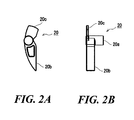
- the ratchet members 20 have a pawl shape, and are swingably mounted on the rope reel 15.
- the ratchet members 20 are fitted onto the protrusions 15b of the rope reel 15 so as to be swingable around the protrusions 15b within a given angular range.
- each of the ratchet members 20 includes a hole as a swinging shaft portion 20a to receive the protrusion 15b of the rope reel 15, a forward end portion 20b disposed on one side of the swinging shaft portion 20a, and a rearward end portion 20c disposed on the other side of the swinging shaft portion 20a.
- the "forward" direction corresponds to the rotational direction (the counter-clockwise direction in FIGs.
- the forward end portion 20b protrudes to the outer diameter direction of the rope reel 15 to be engaged with the driving pulley 18 when the rope reel 15 rotates.
- the rearward end portion 20c on the opposite side moves to the inner diameter direction.
- the ratchet members 20 are urged by the ratchet urging members 21.
- the ratchet urging members 21 are configured by torsional coil springs.
- the driving pulley 18 is mounted on the crankshaft of the engine.
- the rotational force of the rope reel 15 is transmitted to the engine side through the driving pulley 18.
- the driving pulley 18 includes receiving portions 18a that are disposed at regular intervals in the circumferential direction.
- the receiving portions 18a of the driving pulley 18 are engageable with the forward end portions 20b of the ratchet members 20.
- the ratchet guide 22 generally has a circular shape.
- the ratchet guide 22 is rotatably mounted on the reel support shaft 12 with friction resistance, which is provided by the friction spring 17.
- the ratchet guide 22 includes a flange portion 23 having a circular disc shape, and a concave portion 26 disposed in the center of the flange portion 23.
- Rib-like wall portions protrude in the thickness direction from the back surface of the flange portion 23.
- each of the wall portions forms a guide portion 24 and a swinging-prevention portion 25.
- the guide portion 24 is formed to guide the forward end portions 20b of the ratchet members 20 to the outside (the outer diameter direction) of the rope reel 15 when the rope reel 15 rotates in the engine starting direction.
- the swinging-prevention portions 25 is formed to prevent the ratchet members 20 from swinging to the outside (the outer diameter direction) of the rope reel 15 when the ratchet members 20 do not contact the guide portions 24.
- the swinging-prevention portion 25 is formed as a part of the wall portion which extends in the circumferential direction around the axis of the ratchet guide 22.
- the concave portion 26 of the ratchet guide 22 is provided with a through hole 28 in its center.
- the reel support shaft 12 is inserted into the through hole 28.
- a part of the concave portion 26 is stepped to form a retaining portion 27.
- the retaining portion 27 faces the rope reel 15, thereby functioning as a retainer of the rope reel 15 with respect to the reel support shaft 12.
- a spring-receiving portion 29 is provided to receive the friction spring 17.
- the friction spring 17 is disposed between the starter case 11 and the ratchet guide 22, and urges the ratchet guide 22 in a direction of being away from the starter case 11. Since the friction spring 17 urges the ratchet guide 22 toward the washer 14, predetermined friction resistance is provided to the ratchet guide 22.
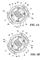
- FIG. 4A shows the original state.
- the rope reel 15 rotates in the engine starting direction, and the ratchet members 20 rotate integrally with the rope reel 15.
- the ratchet guide 22 does not immediately rotate with the rope reel 15 because of the friction resistance provided between the ratchet guide 22 and the reel support shaft 12.
- the forward end portions 20b of the ratchet members 20 contact the guide portions 24 of the ratchet guide 22 as shown in FIG. 4B .
- the forward end portions 20b of the ratchet members 20 are pressed onto the guide portions 24 of the ratchet guide 22, and are caused to swing and protrude to the outer diameter direction as shown in FIG. 5A .
- the ratchet guide 22 and the rope reel 15 relatively rotate to the position shown in FIG. 5B , the ratchet guide 22 is locked by the rope reel 15 (the ratchet members 20), so that the ratchet guide 22 thereafter integrally rotates with the rope reel 15 against the friction resistance by the friction spring 17.
- the forward end portions 20b of the ratchet members 20 protrude to the outer diameter direction, the forward end portions 20b are engageable with the receiving portions 18a of the driving pulley 18.
- the driving pulley 18 also rotates integrally with the rope reel 15.
- the rotational force of the rope reel 15 can be transmitted to the driving pulley 18 (the engine side), thereby starting the engine.
- the rope reel 15 When pulling of the recoil rope 16 is finished, the rope reel 15 is rotated backward (rotated clockwise) from the state shown in FIG. 5B by the rotational force accumulated in the recoil spiral spring 19.
- the ratchet guide 22 and the rope reel 15 rotate relatively in the direction opposite to the previous rotation direction (the engine starting direction)
- the forward end portions 20b of the ratchet members 20 are separated from the guide portions 24, and the ratchet members 20 swing inwardly by the urging force of the ratchet urging members 21.
- the ratchet members 20 swing until the ratchet members 20 return to the retracted position, as shown in FIG. 4A .
- the ratchet members 20 can be reliably held at a retracted position because the swinging-prevention portions 25 are disposed at positions facing the rearward end portions 20c of the ratchet members 20 so as to prevent the forward end portions 20b of the ratchet members 20 from swinging outwardly, as shown in FIG. 4A .
- the guide portions 24 are disposed to guide the forward end portions 20b of the ratchet members 20 to be engaged with the receiving portions 18a of the driving pulley 18, and the swinging-prevention portions 25 are disposed to face the rearward end portions 20c of the ratchet members 20.
- the guide portions 24 and the swinging-prevention portions 25 can be placed close to each other in the circumferential direction, thereby reducing a free running distance of the rope reel 15.
- the free running distance means a distance of movement from when a rotation of the rope reel 15 starts until when the ratchet members 20 are engaged with the driving pulley 18.
- the swinging-prevention portions 25 are disposed on the inner diameter side to contact the rearward end portions 20c of the ratchet members 20.
- the swinging-prevention portions 25 may be provided on the outer diameter side to contact the forward end portions 20b of the ratchet members 20.
- the rib-like wall portions for forming the swinging-prevention portions 25 may protrude from an outer circumferential edge of the flange portion 23 of the ratchet guide 22.
- the rib-like wall portions may be more easily deformed as compared with the case where the rib-like wall portions protrude from the inner diameter side of the flange portion 23. Also, it may become difficult to continuously form the swinging-prevention portions 25 with the guide portions 24 to thereby strengthen them.
- the ratchet guide 22 includes the guide portions 24 that push out the ratchet members 20 to the outer diameter direction when the rope reel 15 rotates in the engine starting direction, and the swinging-prevention portions 25 that prevent the ratchet members 20 from swinging to the outer diameter direction when the ratchet members 20 do not contact the guide portions 24.
- the ratchet members 20 can be pushed back reliably to the retracted position when the rope reel 15 rotates in the direction opposite to the engine starting direction.
- the ratchet guide 22 also functions as a retainer that retains the rope reel 15 with respect to the reel support shaft 12.
- one member, that is the ratchet guide 22 can have at least three functions of guiding the ratchet members 20 to be engaged with the driving pulley 18, preventing the ratchet members 20 from unintentionally swinging, and retaining the rope reel 15.
- many effects can be realized with a small parts count.
- the guide portions 24 are disposed to guide the forward end portions 20b of the ratchet members 20 to be engaged with the receiving portions 18a of the driving pulley 18, and the swinging-prevention portions 25 are disposed to face the rearward end portions 20c of the ratchet members 20.
- the guide portions 24 and the swinging-prevention portions 25 can be placed closely with each other, and it is possible to reduce a free running distance until the ratchet members 20 are engaged with the driving pulley 18 from when the rope reel 15 is rotated to start the engine.
- the ratchet guide 22 includes a plurality (two, in this embodiment) of the guide portions 24 and a plurality (two, in this embodiment) of the swinging-prevention portions 25, correspondingly with the number of the ratchet members 20. That is, the ratchet guide 22 can be applied for a ratchet mechanism having any number of the ratchet members 20. Thus, in the resulting recoil starter 10, stable engagement with the driving pulley can be realized through the plurality of ratchet members 20.
- the guide portions 24 and the swinging-prevention portions 25 are formed by the consecutive wall portions, it is also possible to strengthen the ratchet guide 22 by the consecutive wall portions.
Landscapes
- Engineering & Computer Science (AREA)
- Chemical & Material Sciences (AREA)
- Combustion & Propulsion (AREA)
- Mechanical Engineering (AREA)
- General Engineering & Computer Science (AREA)
- Transmission Devices (AREA)
Applications Claiming Priority (1)
| Application Number | Priority Date | Filing Date | Title |
|---|---|---|---|
| JP2014234419A JP6509530B2 (ja) | 2014-11-19 | 2014-11-19 | リコイルスタータ |
Publications (2)
| Publication Number | Publication Date |
|---|---|
| EP3023629A1 true EP3023629A1 (de) | 2016-05-25 |
| EP3023629B1 EP3023629B1 (de) | 2019-12-25 |
Family
ID=54697459
Family Applications (1)
| Application Number | Title | Priority Date | Filing Date |
|---|---|---|---|
| EP15195206.6A Active EP3023629B1 (de) | 2014-11-19 | 2015-11-18 | Seilzugstarter |
Country Status (4)
| Country | Link |
|---|---|
| US (1) | US9976532B2 (de) |
| EP (1) | EP3023629B1 (de) |
| JP (1) | JP6509530B2 (de) |
| CN (1) | CN105604756B (de) |
Families Citing this family (4)
| Publication number | Priority date | Publication date | Assignee | Title |
|---|---|---|---|---|
| JP6536479B2 (ja) | 2016-05-17 | 2019-07-03 | 株式会社デンソー | 回転機の制御装置 |
| JP7391357B2 (ja) | 2019-09-19 | 2023-12-05 | スターテング工業株式会社 | リコイルスタータ |
| JP7561377B2 (ja) | 2021-03-19 | 2024-10-04 | 本田技研工業株式会社 | リコイルスタータ |
| JP7580767B2 (ja) | 2021-05-27 | 2024-11-12 | スターテング工業株式会社 | リコイルスタータ |
Citations (5)
| Publication number | Priority date | Publication date | Assignee | Title |
|---|---|---|---|---|
| US3871350A (en) * | 1971-07-29 | 1975-03-18 | Eaton Stamping Co | Recoil starter |
| GB2218470A (en) * | 1988-05-11 | 1989-11-15 | Hatz Motoren | Pull cord starter for i.c.engines |
| EP1406007A2 (de) * | 2002-10-02 | 2004-04-07 | Starting Industrial Co., Ltd. | Seilstartvorrichtung |
| JP2012132430A (ja) | 2010-12-01 | 2012-07-12 | Starting Industrial Co Ltd | リコイルスタータ |
| JP2014132159A (ja) | 2013-01-07 | 2014-07-17 | Starting Industrial Co Ltd | リコイルスタータ |
Family Cites Families (12)
| Publication number | Priority date | Publication date | Assignee | Title |
|---|---|---|---|---|
| US4492190A (en) * | 1983-04-20 | 1985-01-08 | Eaton Stamping Company | Recoil starter |
| US4582030A (en) * | 1984-03-02 | 1986-04-15 | Tecumseh Products Company | Mounting recoil starter |
| US5014657A (en) * | 1989-03-24 | 1991-05-14 | Showakiki Industry Co., Ltd. | Recoil starter |
| JP3227376B2 (ja) * | 1995-08-04 | 2001-11-12 | 昭和機器工業株式会社 | リコイルスタータ |
| JPH10184500A (ja) * | 1996-12-20 | 1998-07-14 | Honda Motor Co Ltd | エンジンのリコイル式スタータ |
| JP2001090546A (ja) * | 1999-09-24 | 2001-04-03 | Honda Motor Co Ltd | エンジン |
| US6694941B2 (en) * | 2001-08-24 | 2004-02-24 | Kioritz Corporation | Starter |
| CN2620773Y (zh) | 2003-05-27 | 2004-06-16 | 建设工业(集团)有限责任公司技术中心 | 发动机惯性力启动器 |
| JP5428093B2 (ja) * | 2009-08-29 | 2014-02-26 | スターテング工業株式会社 | 小型エンジンの始動装置 |
| JP5833910B2 (ja) * | 2011-12-19 | 2015-12-16 | スターテング工業株式会社 | リコイルスタータ機構 |
| JP6046895B2 (ja) * | 2012-01-25 | 2016-12-21 | スターテング工業株式会社 | リコイルスタータ |
| CN202970998U (zh) | 2012-05-07 | 2013-06-05 | 隆鑫通用动力股份有限公司 | 手拉启动的发动机 |
-
2014
- 2014-11-19 JP JP2014234419A patent/JP6509530B2/ja active Active
-
2015
- 2015-11-18 US US14/944,908 patent/US9976532B2/en active Active
- 2015-11-18 EP EP15195206.6A patent/EP3023629B1/de active Active
- 2015-11-19 CN CN201510800219.4A patent/CN105604756B/zh active Active
Patent Citations (5)
| Publication number | Priority date | Publication date | Assignee | Title |
|---|---|---|---|---|
| US3871350A (en) * | 1971-07-29 | 1975-03-18 | Eaton Stamping Co | Recoil starter |
| GB2218470A (en) * | 1988-05-11 | 1989-11-15 | Hatz Motoren | Pull cord starter for i.c.engines |
| EP1406007A2 (de) * | 2002-10-02 | 2004-04-07 | Starting Industrial Co., Ltd. | Seilstartvorrichtung |
| JP2012132430A (ja) | 2010-12-01 | 2012-07-12 | Starting Industrial Co Ltd | リコイルスタータ |
| JP2014132159A (ja) | 2013-01-07 | 2014-07-17 | Starting Industrial Co Ltd | リコイルスタータ |
Also Published As
| Publication number | Publication date |
|---|---|
| US9976532B2 (en) | 2018-05-22 |
| JP2016098677A (ja) | 2016-05-30 |
| EP3023629B1 (de) | 2019-12-25 |
| JP6509530B2 (ja) | 2019-05-08 |
| US20160138546A1 (en) | 2016-05-19 |
| CN105604756A (zh) | 2016-05-25 |
| CN105604756B (zh) | 2019-06-14 |
Similar Documents
| Publication | Publication Date | Title |
|---|---|---|
| JP5836713B2 (ja) | リコイルスタータ | |
| US10631529B2 (en) | Torque limiting device for fishing reel and spinning reel | |
| US7093577B2 (en) | Recoil starter | |
| EP3023629A1 (de) | Seilzugstarter | |
| US20170369268A1 (en) | Coating film transfer tool | |
| JP4346922B2 (ja) | リコイルスタータ | |
| JP5101483B2 (ja) | リコイルスタータ | |
| JP2019187342A5 (de) | ||
| JP4792408B2 (ja) | リコイルスタータ | |
| US9322377B2 (en) | Recoil starter mechanism | |
| CN107585128A (zh) | 安全带卷取装置 | |
| JP5416261B2 (ja) | リコイルスタータ | |
| JP7391357B2 (ja) | リコイルスタータ | |
| JP2022181753A (ja) | リコイルスタータ | |
| JP2020044932A (ja) | シートベルトリトラクタ |
Legal Events
| Date | Code | Title | Description |
|---|---|---|---|
| AK | Designated contracting states |
Kind code of ref document: A1 Designated state(s): AL AT BE BG CH CY CZ DE DK EE ES FI FR GB GR HR HU IE IS IT LI LT LU LV MC MK MT NL NO PL PT RO RS SE SI SK SM TR |
|
| AX | Request for extension of the european patent |
Extension state: BA ME |
|
| PUAI | Public reference made under article 153(3) epc to a published international application that has entered the european phase |
Free format text: ORIGINAL CODE: 0009012 |
|
| STAA | Information on the status of an ep patent application or granted ep patent |
Free format text: STATUS: REQUEST FOR EXAMINATION WAS MADE |
|
| 17P | Request for examination filed |
Effective date: 20161121 |
|
| RBV | Designated contracting states (corrected) |
Designated state(s): AL AT BE BG CH CY CZ DE DK EE ES FI FR GB GR HR HU IE IS IT LI LT LU LV MC MK MT NL NO PL PT RO RS SE SI SK SM TR |
|
| GRAP | Despatch of communication of intention to grant a patent |
Free format text: ORIGINAL CODE: EPIDOSNIGR1 |
|
| STAA | Information on the status of an ep patent application or granted ep patent |
Free format text: STATUS: GRANT OF PATENT IS INTENDED |
|
| INTG | Intention to grant announced |
Effective date: 20190917 |
|
| GRAS | Grant fee paid |
Free format text: ORIGINAL CODE: EPIDOSNIGR3 |
|
| GRAA | (expected) grant |
Free format text: ORIGINAL CODE: 0009210 |
|
| STAA | Information on the status of an ep patent application or granted ep patent |
Free format text: STATUS: THE PATENT HAS BEEN GRANTED |
|
| AK | Designated contracting states |
Kind code of ref document: B1 Designated state(s): AL AT BE BG CH CY CZ DE DK EE ES FI FR GB GR HR HU IE IS IT LI LT LU LV MC MK MT NL NO PL PT RO RS SE SI SK SM TR |
|
| REG | Reference to a national code |
Ref country code: GB Ref legal event code: FG4D |
|
| REG | Reference to a national code |
Ref country code: CH Ref legal event code: EP |
|
| REG | Reference to a national code |
Ref country code: DE Ref legal event code: R096 Ref document number: 602015044188 Country of ref document: DE |
|
| REG | Reference to a national code |
Ref country code: AT Ref legal event code: REF Ref document number: 1217399 Country of ref document: AT Kind code of ref document: T Effective date: 20200115 |
|
| REG | Reference to a national code |
Ref country code: IE Ref legal event code: FG4D |
|
| REG | Reference to a national code |
Ref country code: SE Ref legal event code: TRGR |
|
| REG | Reference to a national code |
Ref country code: NL Ref legal event code: MP Effective date: 20191225 |
|
| PG25 | Lapsed in a contracting state [announced via postgrant information from national office to epo] |
Ref country code: LV Free format text: LAPSE BECAUSE OF FAILURE TO SUBMIT A TRANSLATION OF THE DESCRIPTION OR TO PAY THE FEE WITHIN THE PRESCRIBED TIME-LIMIT Effective date: 20191225 Ref country code: LT Free format text: LAPSE BECAUSE OF FAILURE TO SUBMIT A TRANSLATION OF THE DESCRIPTION OR TO PAY THE FEE WITHIN THE PRESCRIBED TIME-LIMIT Effective date: 20191225 Ref country code: GR Free format text: LAPSE BECAUSE OF FAILURE TO SUBMIT A TRANSLATION OF THE DESCRIPTION OR TO PAY THE FEE WITHIN THE PRESCRIBED TIME-LIMIT Effective date: 20200326 Ref country code: NO Free format text: LAPSE BECAUSE OF FAILURE TO SUBMIT A TRANSLATION OF THE DESCRIPTION OR TO PAY THE FEE WITHIN THE PRESCRIBED TIME-LIMIT Effective date: 20200325 Ref country code: BG Free format text: LAPSE BECAUSE OF FAILURE TO SUBMIT A TRANSLATION OF THE DESCRIPTION OR TO PAY THE FEE WITHIN THE PRESCRIBED TIME-LIMIT Effective date: 20200325 Ref country code: FI Free format text: LAPSE BECAUSE OF FAILURE TO SUBMIT A TRANSLATION OF THE DESCRIPTION OR TO PAY THE FEE WITHIN THE PRESCRIBED TIME-LIMIT Effective date: 20191225 |
|
| REG | Reference to a national code |
Ref country code: LT Ref legal event code: MG4D |
|
| PG25 | Lapsed in a contracting state [announced via postgrant information from national office to epo] |
Ref country code: RS Free format text: LAPSE BECAUSE OF FAILURE TO SUBMIT A TRANSLATION OF THE DESCRIPTION OR TO PAY THE FEE WITHIN THE PRESCRIBED TIME-LIMIT Effective date: 20191225 Ref country code: HR Free format text: LAPSE BECAUSE OF FAILURE TO SUBMIT A TRANSLATION OF THE DESCRIPTION OR TO PAY THE FEE WITHIN THE PRESCRIBED TIME-LIMIT Effective date: 20191225 |
|
| PG25 | Lapsed in a contracting state [announced via postgrant information from national office to epo] |
Ref country code: AL Free format text: LAPSE BECAUSE OF FAILURE TO SUBMIT A TRANSLATION OF THE DESCRIPTION OR TO PAY THE FEE WITHIN THE PRESCRIBED TIME-LIMIT Effective date: 20191225 |
|
| PG25 | Lapsed in a contracting state [announced via postgrant information from national office to epo] |
Ref country code: RO Free format text: LAPSE BECAUSE OF FAILURE TO SUBMIT A TRANSLATION OF THE DESCRIPTION OR TO PAY THE FEE WITHIN THE PRESCRIBED TIME-LIMIT Effective date: 20191225 Ref country code: CZ Free format text: LAPSE BECAUSE OF FAILURE TO SUBMIT A TRANSLATION OF THE DESCRIPTION OR TO PAY THE FEE WITHIN THE PRESCRIBED TIME-LIMIT Effective date: 20191225 Ref country code: EE Free format text: LAPSE BECAUSE OF FAILURE TO SUBMIT A TRANSLATION OF THE DESCRIPTION OR TO PAY THE FEE WITHIN THE PRESCRIBED TIME-LIMIT Effective date: 20191225 Ref country code: NL Free format text: LAPSE BECAUSE OF FAILURE TO SUBMIT A TRANSLATION OF THE DESCRIPTION OR TO PAY THE FEE WITHIN THE PRESCRIBED TIME-LIMIT Effective date: 20191225 Ref country code: PT Free format text: LAPSE BECAUSE OF FAILURE TO SUBMIT A TRANSLATION OF THE DESCRIPTION OR TO PAY THE FEE WITHIN THE PRESCRIBED TIME-LIMIT Effective date: 20200520 |
|
| PG25 | Lapsed in a contracting state [announced via postgrant information from national office to epo] |
Ref country code: IS Free format text: LAPSE BECAUSE OF FAILURE TO SUBMIT A TRANSLATION OF THE DESCRIPTION OR TO PAY THE FEE WITHIN THE PRESCRIBED TIME-LIMIT Effective date: 20200425 Ref country code: SK Free format text: LAPSE BECAUSE OF FAILURE TO SUBMIT A TRANSLATION OF THE DESCRIPTION OR TO PAY THE FEE WITHIN THE PRESCRIBED TIME-LIMIT Effective date: 20191225 Ref country code: SM Free format text: LAPSE BECAUSE OF FAILURE TO SUBMIT A TRANSLATION OF THE DESCRIPTION OR TO PAY THE FEE WITHIN THE PRESCRIBED TIME-LIMIT Effective date: 20191225 |
|
| REG | Reference to a national code |
Ref country code: DE Ref legal event code: R097 Ref document number: 602015044188 Country of ref document: DE |
|
| PG25 | Lapsed in a contracting state [announced via postgrant information from national office to epo] |
Ref country code: ES Free format text: LAPSE BECAUSE OF FAILURE TO SUBMIT A TRANSLATION OF THE DESCRIPTION OR TO PAY THE FEE WITHIN THE PRESCRIBED TIME-LIMIT Effective date: 20191225 Ref country code: DK Free format text: LAPSE BECAUSE OF FAILURE TO SUBMIT A TRANSLATION OF THE DESCRIPTION OR TO PAY THE FEE WITHIN THE PRESCRIBED TIME-LIMIT Effective date: 20191225 |
|
| PLBE | No opposition filed within time limit |
Free format text: ORIGINAL CODE: 0009261 |
|
| STAA | Information on the status of an ep patent application or granted ep patent |
Free format text: STATUS: NO OPPOSITION FILED WITHIN TIME LIMIT |
|
| REG | Reference to a national code |
Ref country code: AT Ref legal event code: MK05 Ref document number: 1217399 Country of ref document: AT Kind code of ref document: T Effective date: 20191225 |
|
| PG25 | Lapsed in a contracting state [announced via postgrant information from national office to epo] |
Ref country code: SI Free format text: LAPSE BECAUSE OF FAILURE TO SUBMIT A TRANSLATION OF THE DESCRIPTION OR TO PAY THE FEE WITHIN THE PRESCRIBED TIME-LIMIT Effective date: 20191225 |
|
| 26N | No opposition filed |
Effective date: 20200928 |
|
| PG25 | Lapsed in a contracting state [announced via postgrant information from national office to epo] |
Ref country code: AT Free format text: LAPSE BECAUSE OF FAILURE TO SUBMIT A TRANSLATION OF THE DESCRIPTION OR TO PAY THE FEE WITHIN THE PRESCRIBED TIME-LIMIT Effective date: 20191225 |
|
| PG25 | Lapsed in a contracting state [announced via postgrant information from national office to epo] |
Ref country code: PL Free format text: LAPSE BECAUSE OF FAILURE TO SUBMIT A TRANSLATION OF THE DESCRIPTION OR TO PAY THE FEE WITHIN THE PRESCRIBED TIME-LIMIT Effective date: 20191225 |
|
| PG25 | Lapsed in a contracting state [announced via postgrant information from national office to epo] |
Ref country code: MC Free format text: LAPSE BECAUSE OF FAILURE TO SUBMIT A TRANSLATION OF THE DESCRIPTION OR TO PAY THE FEE WITHIN THE PRESCRIBED TIME-LIMIT Effective date: 20191225 |
|
| REG | Reference to a national code |
Ref country code: CH Ref legal event code: PL |
|
| GBPC | Gb: european patent ceased through non-payment of renewal fee |
Effective date: 20201118 |
|
| PG25 | Lapsed in a contracting state [announced via postgrant information from national office to epo] |
Ref country code: LU Free format text: LAPSE BECAUSE OF NON-PAYMENT OF DUE FEES Effective date: 20201118 |
|
| REG | Reference to a national code |
Ref country code: BE Ref legal event code: MM Effective date: 20201130 |
|
| PG25 | Lapsed in a contracting state [announced via postgrant information from national office to epo] |
Ref country code: CH Free format text: LAPSE BECAUSE OF NON-PAYMENT OF DUE FEES Effective date: 20201130 Ref country code: LI Free format text: LAPSE BECAUSE OF NON-PAYMENT OF DUE FEES Effective date: 20201130 |
|
| PG25 | Lapsed in a contracting state [announced via postgrant information from national office to epo] |
Ref country code: FR Free format text: LAPSE BECAUSE OF NON-PAYMENT OF DUE FEES Effective date: 20201130 Ref country code: IE Free format text: LAPSE BECAUSE OF NON-PAYMENT OF DUE FEES Effective date: 20201118 |
|
| PG25 | Lapsed in a contracting state [announced via postgrant information from national office to epo] |
Ref country code: GB Free format text: LAPSE BECAUSE OF NON-PAYMENT OF DUE FEES Effective date: 20201118 |
|
| PG25 | Lapsed in a contracting state [announced via postgrant information from national office to epo] |
Ref country code: TR Free format text: LAPSE BECAUSE OF FAILURE TO SUBMIT A TRANSLATION OF THE DESCRIPTION OR TO PAY THE FEE WITHIN THE PRESCRIBED TIME-LIMIT Effective date: 20191225 Ref country code: MT Free format text: LAPSE BECAUSE OF FAILURE TO SUBMIT A TRANSLATION OF THE DESCRIPTION OR TO PAY THE FEE WITHIN THE PRESCRIBED TIME-LIMIT Effective date: 20191225 Ref country code: CY Free format text: LAPSE BECAUSE OF FAILURE TO SUBMIT A TRANSLATION OF THE DESCRIPTION OR TO PAY THE FEE WITHIN THE PRESCRIBED TIME-LIMIT Effective date: 20191225 |
|
| PG25 | Lapsed in a contracting state [announced via postgrant information from national office to epo] |
Ref country code: MK Free format text: LAPSE BECAUSE OF FAILURE TO SUBMIT A TRANSLATION OF THE DESCRIPTION OR TO PAY THE FEE WITHIN THE PRESCRIBED TIME-LIMIT Effective date: 20191225 |
|
| PG25 | Lapsed in a contracting state [announced via postgrant information from national office to epo] |
Ref country code: BE Free format text: LAPSE BECAUSE OF NON-PAYMENT OF DUE FEES Effective date: 20201130 |
|
| PGFP | Annual fee paid to national office [announced via postgrant information from national office to epo] |
Ref country code: DE Payment date: 20250930 Year of fee payment: 11 |
|
| PGFP | Annual fee paid to national office [announced via postgrant information from national office to epo] |
Ref country code: IT Payment date: 20251022 Year of fee payment: 11 |
|
| PGFP | Annual fee paid to national office [announced via postgrant information from national office to epo] |
Ref country code: SE Payment date: 20251001 Year of fee payment: 11 |