EP3023633B1 - Verfahren und system zur wartung eines windturbinenrotors - Google Patents
Verfahren und system zur wartung eines windturbinenrotors Download PDFInfo
- Publication number
- EP3023633B1 EP3023633B1 EP15195031.8A EP15195031A EP3023633B1 EP 3023633 B1 EP3023633 B1 EP 3023633B1 EP 15195031 A EP15195031 A EP 15195031A EP 3023633 B1 EP3023633 B1 EP 3023633B1
- Authority
- EP
- European Patent Office
- Prior art keywords
- rotor
- rotor blade
- blade
- servicing
- wind turbine
- Prior art date
- Legal status (The legal status is an assumption and is not a legal conclusion. Google has not performed a legal analysis and makes no representation as to the accuracy of the status listed.)
- Active
Links
Images







Classifications
-
- F—MECHANICAL ENGINEERING; LIGHTING; HEATING; WEAPONS; BLASTING
- F03—MACHINES OR ENGINES FOR LIQUIDS; WIND, SPRING, OR WEIGHT MOTORS; PRODUCING MECHANICAL POWER OR A REACTIVE PROPULSIVE THRUST, NOT OTHERWISE PROVIDED FOR
- F03D—WIND MOTORS
- F03D80/00—Details, components or accessories not provided for in groups F03D1/00 - F03D17/00
- F03D80/50—Maintenance or repair
-
- B—PERFORMING OPERATIONS; TRANSPORTING
- B66—HOISTING; LIFTING; HAULING
- B66F—HOISTING, LIFTING, HAULING OR PUSHING, NOT OTHERWISE PROVIDED FOR, e.g. DEVICES WHICH APPLY A LIFTING OR PUSHING FORCE DIRECTLY TO THE SURFACE OF A LOAD
- B66F3/00—Devices, e.g. jacks, adapted for uninterrupted lifting of loads
- B66F3/24—Devices, e.g. jacks, adapted for uninterrupted lifting of loads fluid-pressure operated
-
- F—MECHANICAL ENGINEERING; LIGHTING; HEATING; WEAPONS; BLASTING
- F03—MACHINES OR ENGINES FOR LIQUIDS; WIND, SPRING, OR WEIGHT MOTORS; PRODUCING MECHANICAL POWER OR A REACTIVE PROPULSIVE THRUST, NOT OTHERWISE PROVIDED FOR
- F03D—WIND MOTORS
- F03D1/00—Wind motors with rotation axis substantially parallel to the air flow entering the rotor
- F03D1/06—Rotors
-
- F—MECHANICAL ENGINEERING; LIGHTING; HEATING; WEAPONS; BLASTING
- F03—MACHINES OR ENGINES FOR LIQUIDS; WIND, SPRING, OR WEIGHT MOTORS; PRODUCING MECHANICAL POWER OR A REACTIVE PROPULSIVE THRUST, NOT OTHERWISE PROVIDED FOR
- F03D—WIND MOTORS
- F03D13/00—Assembly, mounting or commissioning of wind motors; Arrangements specially adapted for transporting wind motor components
- F03D13/10—Assembly of wind motors; Arrangements for erecting wind motors
-
- F—MECHANICAL ENGINEERING; LIGHTING; HEATING; WEAPONS; BLASTING
- F03—MACHINES OR ENGINES FOR LIQUIDS; WIND, SPRING, OR WEIGHT MOTORS; PRODUCING MECHANICAL POWER OR A REACTIVE PROPULSIVE THRUST, NOT OTHERWISE PROVIDED FOR
- F03D—WIND MOTORS
- F03D80/00—Details, components or accessories not provided for in groups F03D1/00 - F03D17/00
- F03D80/70—Bearing or lubricating arrangements
-
- F—MECHANICAL ENGINEERING; LIGHTING; HEATING; WEAPONS; BLASTING
- F05—INDEXING SCHEMES RELATING TO ENGINES OR PUMPS IN VARIOUS SUBCLASSES OF CLASSES F01-F04
- F05B—INDEXING SCHEME RELATING TO WIND, SPRING, WEIGHT, INERTIA OR LIKE MOTORS, TO MACHINES OR ENGINES FOR LIQUIDS COVERED BY SUBCLASSES F03B, F03D AND F03G
- F05B2230/00—Manufacture
- F05B2230/60—Assembly methods
- F05B2230/61—Assembly methods using auxiliary equipment for lifting or holding
-
- Y—GENERAL TAGGING OF NEW TECHNOLOGICAL DEVELOPMENTS; GENERAL TAGGING OF CROSS-SECTIONAL TECHNOLOGIES SPANNING OVER SEVERAL SECTIONS OF THE IPC; TECHNICAL SUBJECTS COVERED BY FORMER USPC CROSS-REFERENCE ART COLLECTIONS [XRACs] AND DIGESTS
- Y02—TECHNOLOGIES OR APPLICATIONS FOR MITIGATION OR ADAPTATION AGAINST CLIMATE CHANGE
- Y02E—REDUCTION OF GREENHOUSE GAS [GHG] EMISSIONS, RELATED TO ENERGY GENERATION, TRANSMISSION OR DISTRIBUTION
- Y02E10/00—Energy generation through renewable energy sources
- Y02E10/70—Wind energy
- Y02E10/72—Wind turbines with rotation axis in wind direction
-
- Y—GENERAL TAGGING OF NEW TECHNOLOGICAL DEVELOPMENTS; GENERAL TAGGING OF CROSS-SECTIONAL TECHNOLOGIES SPANNING OVER SEVERAL SECTIONS OF THE IPC; TECHNICAL SUBJECTS COVERED BY FORMER USPC CROSS-REFERENCE ART COLLECTIONS [XRACs] AND DIGESTS
- Y02—TECHNOLOGIES OR APPLICATIONS FOR MITIGATION OR ADAPTATION AGAINST CLIMATE CHANGE
- Y02P—CLIMATE CHANGE MITIGATION TECHNOLOGIES IN THE PRODUCTION OR PROCESSING OF GOODS
- Y02P70/00—Climate change mitigation technologies in the production process for final industrial or consumer products
- Y02P70/50—Manufacturing or production processes characterised by the final manufactured product
-
- Y—GENERAL TAGGING OF NEW TECHNOLOGICAL DEVELOPMENTS; GENERAL TAGGING OF CROSS-SECTIONAL TECHNOLOGIES SPANNING OVER SEVERAL SECTIONS OF THE IPC; TECHNICAL SUBJECTS COVERED BY FORMER USPC CROSS-REFERENCE ART COLLECTIONS [XRACs] AND DIGESTS
- Y10—TECHNICAL SUBJECTS COVERED BY FORMER USPC
- Y10T—TECHNICAL SUBJECTS COVERED BY FORMER US CLASSIFICATION
- Y10T29/00—Metal working
- Y10T29/49—Method of mechanical manufacture
- Y10T29/49316—Impeller making
- Y10T29/49318—Repairing or disassembling
Definitions
- a modem wind turbine typically includes a tower, generator, gearbox, nacelle, and one or more rotor blades.
- the rotor blades capture kinetic energy of the wind using known foil principles.
- the rotor blades transmit the kinetic energy in the form of rotational energy so as to turn a shaft coupling the rotor blades to a gearbox, or if a gearbox is not used, directly to the generator.
- the generator then converts the mechanical energy to electrical energy.
- a power converter typically regulates the flow of electrical power between the generator and a grid.
- Each rotor blade 22 may be spaced about the hub 20 to facilitate rotating the rotor 18 to enable kinetic energy to be transferred from the wind into usable mechanical energy, and subsequently, electrical energy.
- the hub 20 may be rotatably coupled to an electric generator (not shown) positioned within the nacelle 16 to permit electrical energy to be produced.
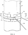
- one or more sock cables 108, 110 may also be coupled to the blade sock 100 and may extend downward to a location adjacent to the support surface 14.
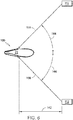
- the system includes a first sock cable 108 and a second sock cable 110 coupled between the blade sock 100 and corresponding winches 112 disposed on and/or adjacent to the support surface 14.
- the sock cables 108, 110 may, for example, be utilized to assist in aligning the blade sock 100 with the rotor blade 22 as the sock 100 is being lifted up onto the blade 22 via the lift cables 106.
- the blade sock 100 may include a sock strap 114 generally defining a closed shape configured to extend around the outer perimeter of the rotor blade 22.
- the blade sock 100 may include one or more edge supports 116, 118 positioned between the sock strap 114 and the rotor blade 22.
- the blade sock 100 includes both a leading edge support 116 positioned between the sock strap 114 and the rotor blade 22 around the location of the leading edge 34 of the blade 22 and a trailing edge support 118 positioned between the sock strap 114 and the rotor blade 22 around the location of the trailing edge 36 of the blade 22.
- the strap 114 may be configured to tighten around the outer perimeter of the rotor blade 22, thereby securing the blade sock 100 to the rotor blade 22.
- edge supports 116, 118 are shown in the illustrated embodiments as two separate components, the edge supports 116, 118 may, instead, be configured as a single component configured to extend around the entire outer perimeter of the rotor blade 22. Additionally, in alternative embodiments, the blade sock 100 may only include one of the edge supports 116, 118, such as by only including the trailing edge support 118.
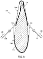
- the sock strap 114 may have any other suitable configuration that allows it to be tightened around the rotor blade 22 using the sock cables 108, 110.
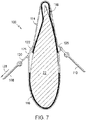
- the sock strap 114 may be configured similar to a choker-type lifting sling. An example of such a configuration is illustrated, for example, in FIG. 7 .
- the sock strap 114 may be configured to be looped around the rotor blade 22 once, with the first end 120 of the sock strap 114 being received through the mount ring 126 secured to the second end 122 of the strap 114.
- the sock cable 108 may be used to apply a tightening force through the sock strap (as indicated by arrow 128) in order to tighten the sock strap 114 around the rotor blade 22.
- each sock cable 108, 110 may be used to apply a tightening force (as indicated by arrows 128) through the first and second strap portions 114A, 114B that allows the sock strap to be tightened around the rotor blade 22.
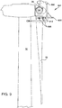
- the clamp assembly 910 is configured to clamp onto rotor blade 22 so that it may be lowered from and raised back to hub 20.
- the third rotor blade 22 is oriented generally in the 6 o'clock position, or in other words rotor blade 22 points generally downward towards the ground or other supporting surface.
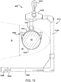
- the clamp assembly 910 is comprised of a generally C-shaped clamp having articulated arms 912.
- the arms 912 are configured to open to pass over the root section of the third rotor blade 22 and to close and clamp onto the root section.
- a hinge 914 may be used to pivot a distal end of arm 912 so that it can open and close.
- the arms 912 may be opened and closed (i.e., activated) manually or by electric, hydraulic or pneumatic systems.
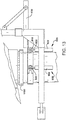
- FIG. 12 illustrates a top view of one example of a clamp assembly 1200, according to an aspect of the present invention.
- the clamp assembly 1200 (which may be used in place of clamp assembly 910) may include a plurality of curved clamp members 1202 configured to be engaged around the outer circumference of the rotor blade 22.
- each clamp member 1202 may be configured to extend circumferentially around a portion of the blade root 24 of the rotor blade 22.
- each clamp member 1202 may be configured to be coupled to any adjacent clamp member(s) 1202 via a pivotal connection. For example, as particularly shown in FIG.
- a hinge pin 1204 may be configured to extend through the ends of each pair of adjacent clamp members 1202, thereby allowing such clamp members to be pivoted or rotated relative to one another. As such, when the clamp assembly 1200 is properly positioned along the blade root 24 at its desired installation location, the clamp members 1202 may be pivoted relative to one another to allow the clamp assembly 1200 to be tightened and/or engaged around the blade root 24.
- one or more clamp pads 1216 may be secured to one or more of the clamp members 1202 such that the clamp pads 1216 are positioned directly between the clamp member(s) 1202 and the rotor blade 22 when the clamp assembly 1200 is installed around the blade root 24.
- the clamp pads 1216 may have a friction coating or surface that allows for improved gripping of the rotor blade surface when the clamp members 1202 are engaged around the blade root 24.
- the clamp pads 1216 may be formed from a foamed material or other suitable cushioning material so as to provide a layer of protection for the outer surface of the rotor blade 22.
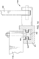
- FIG. 14 illustrates a partial, cross-sectional view of the slide assembly 930.
- the slide assembly 930 has at least two sliding rails 932 that are configured to slide back and forth (i.e., linearly) along frame rails 931.
- the rotor part 1100 can be rested upon (or attached to) the sliding rails 932, so that the rotor part 1100 can be moved away from or towards the wind turbine 10.
- the sliding rails 932 may ride on a plurality of bearings 934 to aid in linear translation of the rails 932.
- one or more threaded holes 936 may be provided for attachment of the rotor part, if desired.
- the slide assembly 930 can be attached to the rotor servicing fixture by a plurality of support members 938.
- FIGS. 15-17 another embodiment of suitable components that may be included within a lowering system to initially lower the rotor blade 22 from the hub 20 is illustrated in accordance with aspects of the present subject matter.
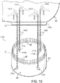
- FIG. 15 illustrates a partial perspective view of the hub 20, the rotor blade 22 and the pitch bearing 1100 of the wind turbine 10 after the blade 22 has been lowered from the hub 20 by an initial vertical distance 1501.
- FIG. 16 illustrates a partial, perspective view of the interior of the hub 20 at the interface between the rotor blade 22 and the pitch bearing 1100 prior to the blade 22 being lowered relative to the hub 20.
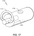
- FIG. 17 illustrates a perspective view of one embodiment of a modified barrel-type support nut 1700 configured for use in the illustrated lowered system in accordance with aspects of the present invention.
- each support nut 1700 may include a laterally extending threaded opening 1708 defined through one of the sides of the nut 1700.
- the opening 1708 may allow for a suitable coupling device 1710 (e.g., a swivel eye, mount ring, mount hook or any other suitable attachment mechanism) to be secured to the support nut 1700 for coupling each support cable 1502 to the rotor blade 22.
- a suitable coupling device 1710 e.g., a swivel eye, mount ring, mount hook or any other suitable attachment mechanism
- four support nuts 1700 may be installed through the blade root 24 in place of the existing barrel nuts 44 to allow four corresponding support cables 1502 to be coupled to the rotor blade 22.
- any other suitable number of support nuts 1700 may be secured within the blade root 24 to provide a means for coupling a corresponding number of support cables 1502 to the rotor blade 22, such as by installing less than four support nuts 1700 within the blade root 24 (e.g., two or three support nuts) or greater than four support nuts 1700 within the blade root 24 (e.g., five, six or more support nuts).
- the support nuts 1700 may be configured to be maintained in position relative to the rotor blade 22 using any suitable attachment means. For instance, in one embodiment, once a given support nut 1700 is inserted within the blade root 24, a corresponding root bolt 46 may be inserted through the pitch bearing 1100 and screwed into the vertically extending opening 1706 of the support nut 1700 in order to secure the nut 1700 within the blade root 24. Alternatively, as shown in FIG. 16 , an alignment pin 1512 may be configured to be inserted through the pitch bearing 1100 and screwed into the vertically extending opening 1706 of each support nut 1700.
- Each support cable 1502 may be configured to extend from one of the support nuts 1700 to a corresponding cable translation device 1510 positioned within the hub 20.
- the cable translation device 1510 may correspond to cable hoists (including chain hoists) configured to be mounted to and/or supported by any suitable wind turbine component(s) positioned within the hub 20 (e.g., the hub gusset(s), joist(s) and/or any other suitable component(s)).
- cable hoists may be configured to allow suitable cables to be passed therethrough in a controlled manner.
- such cable hoists may be utilized to safely and effectively lower the rotor blade 22 relative to the hub 20.
- each support cable 1502 may generally correspond to any suitable elongated cable-like object that has a rated load capacity sufficient to handle the weight of the rotor blade 22.
- the support cables 1502 are configured as metal chains.
- the support cables 1502 may correspond to steel cables or any other suitable wire ropes.
- each support cable 1502 may generally be configured to define any suitable length that permits the cables 1502 to be utilized to lower the rotor blade 22 away from the hub 20 by the initial vertical distance 1501.
- the support cables 1502 may also be connected to blade 22 by cutting a hole into the blade root 24 to install an attachment to the root bolts 46.
- FIG. 18 is a flowchart of a method 1800 for servicing a rotor 18 of a wind turbine 10, according to an aspect of the present invention.
- the method 1800 includes the steps of, attaching 1810 a rotor servicing fixture 900 to the rotor 18, attaching 1820 a clamp assembly 910 onto a rotor blade 22, lowering 930 the rotor blade 22 by a predetermined amount and servicing 940 a rotor part 1100.
- the rotor servicing fixture may be brought to the rotor 18/hub 20 with a crane (not shown).
- An advantage of the present invention is that a smaller and cheaper crane may be used for this operation, as the crane need only lift and transport the rotor servicing fixture 900 and not the entire rotor 18.
- the rotor 18 is much heavier than the rotor servicing fixture.
- the rotor servicing fixture 900 is attached to and supported by a first rotor blade and a second rotor blade.
- the first and second rotor blades would preferably be oriented in the 10 o'clock and 2 o'clock positions.
- a lower part of the rotor servicing fixture contact the tower 12 of the wind turbine 10.
- the clamp assembly 910 is attached to a third rotor blade 22.
- the third rotor blade would be oriented in the 6 o'clock position (or pointing generally downwardly).
- the clamp assembly 910 is now clamped onto the third rotor blade by a pair of articulated arms.
- the clamp assembly can now support the weight of the third rotor blade via the lifting assembly and rotor servicing fixture.
- the lowering step 1830 lowers the third rotor blade by a predetermined amount with the clamp assembly 910 and the lifting assembly 920.
- the predetermined amount may be about 3 to about 6 feet, or any suitable amount as desired in the specific application.
- the rotor part is serviced. This could include, removing, replacing repairing or installing the rotor part.
- the rotor part may be a pitch bearing, pitch motor, pitch controller or any other part or system that is in the blades or hub.
- the servicing is performed without removing the rotor from the wind turbine. As mentioned before, this is a very big advantage as the entire rotor does not have to be removed from the wind turbine to service the rotor part.
- a transporting step transports the rotor part with a slide assembly. The slide assembly supports the rotor part and is configured to slidably move the rotor part away from or towards the wind turbine.
Landscapes
- Engineering & Computer Science (AREA)
- Life Sciences & Earth Sciences (AREA)
- Mechanical Engineering (AREA)
- Sustainable Development (AREA)
- Sustainable Energy (AREA)
- Chemical & Material Sciences (AREA)
- Combustion & Propulsion (AREA)
- General Engineering & Computer Science (AREA)
- Geology (AREA)
- Structural Engineering (AREA)
- Wind Motors (AREA)
Claims (15)
- System (901) zur Ermöglichung der Wartung eines Rotors (18) einer Windturbine (10), umfassend:eine Rotorwartungseinrichtung (900), die so ausgebildet ist, dass sie an einem ersten Rotorblatt (22) und an einem zweiten Rotorblatt (22) angebracht und dadurch gehalten wird, wobei die Rotorwartungseinrichtung (900) so ausgebildet ist, dass sie mit einem Turm (12) der Windturbine (10) in Kontakt tritt;eine Klammeranordnung (910), die mit der Rotorwartungseinrichtung (900) verbunden ist, wobei die Klammeranordnung (910) so ausgebildet ist, dass sie an ein drittes Rotorblatt (22) geklemmt wird, wobei die Klammeranordnung (910) so ausgebildet ist, dass sie das dritte Rotorblatt (22) von einer Nabe (20) absenkt und das dritte untere Blatt (22) zu der Nabe (20) zurück anhebt;eine Hebeanordnung (920), die mit der Rotorwartungseinrichtung (900) und der Klammeranordnung (910) verbunden ist, wobei die Hebeanordnung (920) so ausgebildet ist, dass sie das dritte Rotorblatt (22) über die Klammeranordnung (910) anhebt und absenkt;eine Gleitanordnung (930), die mit der Rotorwartungseinrichtung (900) verbunden ist, wobei die Gleitanordnung (930) so ausgebildet ist, dass sie einen Rotorteil hält und den Rotorteil gleitfähig von der Windturbine (10) weg oder zu dieser hin bewegt; undwobei das System (901) ermöglicht, dass der Rotorteil abgenommen oder ausgetauscht wird, ohne dass es nötig ist, den Rotor (18) von der Windturbine (10) abzunehmen.
- System (901) nach Anspruch 1, wobei die Rotorwartungseinrichtung (900) ferner Folgendes umfasst:einen ersten Schenkel und einen zweiten Schenkel, wobei sowohl der erste Schenkel als auch der zweite Schenkel so ausgebildet ist, dass er mit dem Turm der Windturbine (10) in Kontakt tritt; undwobei sowohl der erste Schenkel als auch der zweite Schenkel einen verstellbaren Verlängerungsabschnitt umfasst.
- System (901) nach Anspruch 1 oder Anspruch 2, wobei die Rotorwartungseinrichtung (900) ferner Folgendes umfasst:einen Hauptkörper mit einem senkrechten Halteabschnitt, der mit dem ersten Schenkel und dem zweiten Schenkel verbunden ist, wobei der senkrechte Halteabschnitt mit einem oberen Abschnitt, der ein Hebeelement aufweist, das zur Anbringung an einem Kran ausgebildet ist, verbunden ist;wobei der obere Abschnitt mit einer Rotorblattklammeranordnung verbunden ist, die so ausgebildet ist, dass sie an dem ersten Rotorblatt und dem zweiten Rotorblatt angebracht wird, wenn sowohl das erste Rotorblatt als auch das zweite Rotorblatt an dem Rotor angebracht bleiben; undwobei das erste Rotorblatt im Allgemeinen in einer Zehn-Uhr-Stellung ausgerichtet ist und das zweite Rotorblatt im Allgemeinen in einer Zwei-Uhr-Stellung ausgerichtet ist.
- System (901) nach einem der vorhergehenden Ansprüche, wobei die Klammeranordnung (910) ferner Folgendes umfasst:eine im Allgemeinen C-förmige Klammer mit Gelenkarmen, wobei die Arme so ausgebildet sind, dass sie sich öffnen, um über einen Wurzelabschnitt des dritten Rotorblatts zu verlaufen, und sich schließen und an den Wurzelabschnitt geklemmt werden.
- System (901) nach Anspruch 4, wobei die Gelenkarme wenigstens eines aus hydraulisch aktiviert, pneumatisch aktiviert oder durch ein Kabel, einen Riemen oder eine Kette um den Wurzelabschnitt festgezogen sind.
- System (901) nach einem der vorhergehenden Ansprüche, wobei die Hebeanordnung (920) ferner Folgendes umfasst:mehrere Zylinder die so ausgebildet sind, dass sie angehoben oder abgesenkt werden;wobei die mehreren Zylinder hydraulisch aktiviert oder pneumatisch aktiviert werden.
- System (901) nach einem der vorhergehenden Ansprüche, wobei die Gleitanordnung (930) ferner Folgendes umfasst:einen Rahmen mit wenigstens zwei Gleitschienen, wobei die Gleitschienen vor und zurück gleiten, um zu gestatten, dass der Rotorteil von der Windturbine weg oder zu dieser hin bewegt wird.
- System (901) nach einem der vorhergehenden Ansprüche, wobei der Rotorteil ein Pitchlager ist.
- Verfahren (1800) zum Warten eines Rotors (18) einer Windturbine (10), umfassend:Anbringen (1810) einer Rotorwartungseinrichtung (900) an dem Rotor der Windturbine, wobei die Rotorwartungseinrichtung (900) so ausgebildet ist, dass sie an einem ersten Rotorblatt (22) und an einem zweiten Rotorblatt (22) angebracht und dadurch gehalten wird, wobei die Rotorwartungseinrichtung (900) so ausgebildet ist, dass sie mit einem Turm (12) der Windturbine (10) in Kontakt tritt;Anbringen (1820) einer Klammeranordnung (910) an einem dritten Rotorblatt (22), wobei die Klammeranordnung (910) mit der Rotorwartungseinrichtung verbunden ist, wobei die Klammeranordnung (910) so ausgebildet ist, dass sie an das dritte Rotorblatt (22) geklemmt wird;Absenken (1830) des dritten Rotorblatts (22) um ein vorherbestimmtes Ausmaß mit der Klammeranordnung (910) und eine Hebeanordnung (920), wobei die Klammeranordnung (910) so ausgebildet ist, dass sie das dritte Rotorblatt (22) von einer Nabe (20) absenkt und das dritte untere Blatt (22) zu der Nabe (20) zurück anhebt, und die Hebeanordnung (920) mit der Rotorwartungseinrichtung und der Klammeranordnung (910) verbunden ist, wobei die Hebeanordnung (920) so ausgebildet ist, dass sie das dritte Rotorblatt (22) über die Klammeranordnung (910) anhebt und absenkt;Warten (1840) eines Rotorteils, wobei die Wartung durchgeführt wird, ohne den Rotor (20) von der Windturbine (10) abzunehmen.
- Verfahren (1800) nach Anspruch 9, ferner umfassend:Transportieren des Rotorteils mit einer Gleitanordnung (930), wobei die Gleitanordnung (930) mit der Rotorwartungseinrichtung verbunden ist und so ausgebildet ist, dass sie den Rotorteil hält und den Rotorteil gleitfähig von der Windturbine (10) weg oder zu dieser hin bewegt.
- Verfahren (1800) nach Anspruch 9 oder Anspruch 10, wobei der Schritt (1810) des Anbringens einer Rotorwartungseinrichtung ferner Folgendes umfasst:Anheben der Rotorwartungseinrichtung mittels eines Krans zu dem Rotor.
- Verfahren (1800) nach einem der Ansprüche 9 bis 11, wobei die Rotorwartungseinrichtung (900) ferner Folgendes umfasst:einen ersten Schenkel und einen zweiten Schenkel, wobei sowohl der erste Schenkel als auch der zweite Schenkel so ausgebildet ist, dass er mit dem Turm der Windturbine in Kontakt tritt; undwobei sowohl der erste Schenkel als auch der zweite Schenkel einen verstellbaren Verlängerungsabschnitt umfasst.
- Verfahren (1800) nach einem der Ansprüche 9 bis 12, wobei die Rotorwartungseinrichtung (900) ferner Folgendes umfasst:einen Hauptkörper mit einem senkrechten Halteabschnitt, der mit dem ersten Schenkel und dem zweiten Schenkel verbunden ist, wobei der senkrechte Halteabschnitt mit einem oberen Abschnitt, der ein Hebeelement aufweist, das zur Anbringung an einem Kran ausgebildet ist, verbunden ist;wobei der obere Abschnitt mit einer Rotorblattklammeranordnung verbunden ist, die so ausgebildet ist, dass sie an dem ersten Rotorblatt und dem zweiten Rotorblatt angebracht wird, wenn sowohl das erste Rotorblatt als auch das zweite Rotorblatt an dem Rotor (20) angebracht bleiben; undwobei das erste Rotorblatt (22) im Allgemeinen in einer Zehn-Uhr-Stellung ausgerichtet ist und das zweite Rotorblatt im Allgemeinen in einer Zwei-Uhr-Stellung ausgerichtet ist.
- Verfahren (1800) nach einem der Ansprüche 9 bis 13, wobei der Wartungsschritt (1840) das Abnehmen oder Austauschen des Rotorteils umfasst.
- Verfahren (1800) nach Anspruch 14, wobei das Verfahren ferner den folgenden Schritt umfasst:Zurückheben des dritten Rotorblatts (22) bis zu der Nabe (20) unter Verwendung der Hebeanordnung (920) und Wiederverbinden des dritten Rotorblatts (22) mit der Nabe (20).
Applications Claiming Priority (1)
| Application Number | Priority Date | Filing Date | Title |
|---|---|---|---|
| US14/548,530 US9850880B2 (en) | 2014-11-20 | 2014-11-20 | System for servicing wind turbine rotor |
Publications (2)
| Publication Number | Publication Date |
|---|---|
| EP3023633A1 EP3023633A1 (de) | 2016-05-25 |
| EP3023633B1 true EP3023633B1 (de) | 2017-10-18 |
Family
ID=54548089
Family Applications (1)
| Application Number | Title | Priority Date | Filing Date |
|---|---|---|---|
| EP15195031.8A Active EP3023633B1 (de) | 2014-11-20 | 2015-11-17 | Verfahren und system zur wartung eines windturbinenrotors |
Country Status (3)
| Country | Link |
|---|---|
| US (1) | US9850880B2 (de) |
| EP (1) | EP3023633B1 (de) |
| DK (1) | DK3023633T3 (de) |
Families Citing this family (13)
| Publication number | Priority date | Publication date | Assignee | Title |
|---|---|---|---|---|
| US9745953B2 (en) * | 2012-10-23 | 2017-08-29 | General Electric Company | Method and system for replacing a single wind turbine blade |
| ES2556997B1 (es) * | 2014-07-07 | 2016-12-12 | Gamesa Innovation & Technology, S.L. | Método y dispositivo de sustitución de pala en aerogeneradores |
| DK3263888T3 (da) * | 2016-06-30 | 2023-11-13 | Siemens Gamesa Renewable Energy As | Fremgangsmåde til håndtering af en vindmøllerotorbladspitchlejeenhed |
| US10494235B2 (en) * | 2016-12-06 | 2019-12-03 | General Electric Company | Crane system and an associated method thereof |
| ES2876008T3 (es) | 2017-03-29 | 2021-11-11 | Gen Electric | Conjunto de grúa de buje para una turbina eólica |
| CA3071958C (en) * | 2017-08-03 | 2023-10-03 | Barnhart Crane and Rigging Co. | Wind tubine bearing removal and installation device and method |
| WO2019195322A1 (en) * | 2018-04-02 | 2019-10-10 | Tpi Composites, Inc. | Individual emergency brake system for wind turbine blade rotating device |
| JP7459117B2 (ja) * | 2019-01-10 | 2024-04-01 | ヴェスタス ウィンド システムズ エー/エス | 風力タービン用発電機におけるステータ取り付けに関する改善方法 |
| WO2021021160A1 (en) | 2019-07-31 | 2021-02-04 | General Electric Company | System and method for servicing a jointed rotor blade of a wind turbine |
| EP3828121B1 (de) | 2019-11-26 | 2024-02-28 | General Electric Renovables España S.L. | Kran und verfahren zum errichten eines turms |
| US12188453B2 (en) * | 2020-04-02 | 2025-01-07 | Aerones, Inc. | Arrangement for lowering and raising service tools used for wind turbine blade and tower maintenance |
| EP4019770A1 (de) * | 2020-12-23 | 2022-06-29 | General Electric Renovables España S.L. | Schaufelhebevorrichtung zur montage einer schaufel an einer rotornabe einer windturbine oder zur demontage einer schaufel von einer rotornabe einer windturbine |
| EP4095086B1 (de) | 2021-05-26 | 2025-02-26 | General Electric Renovables España S.L. | Krananlagen und verfahren zur errichtung von türmen und windturbinen |
Family Cites Families (5)
| Publication number | Priority date | Publication date | Assignee | Title |
|---|---|---|---|---|
| US20100139062A1 (en) | 2009-02-25 | 2010-06-10 | General Electric Company | Lowering and raising a single wind turbine rotor blade from six-o'clock position |
| CA2784625A1 (en) | 2009-11-30 | 2011-06-03 | Clipper Windpower, Inc. | Wind turbine blade lowering apparatus |
| EP2388480B1 (de) | 2010-08-31 | 2013-10-30 | Mitsubishi Heavy Industries, Ltd. | Wartungsverfahren für einen windturbinengenerator |
| ES2564260T3 (es) | 2010-11-18 | 2016-03-21 | Vestas Wind Systems A/S | Método para manipular sin grúa una pala de turbina eólica por medio de un buje de turbina |
| US9394886B2 (en) | 2013-03-07 | 2016-07-19 | General Electric Company | System and method for re-indexing a pitch bearing of a wind turbine |
-
2014
- 2014-11-20 US US14/548,530 patent/US9850880B2/en active Active
-
2015
- 2015-11-17 DK DK15195031.8T patent/DK3023633T3/en active
- 2015-11-17 EP EP15195031.8A patent/EP3023633B1/de active Active
Non-Patent Citations (1)
| Title |
|---|
| None * |
Also Published As
| Publication number | Publication date |
|---|---|
| US9850880B2 (en) | 2017-12-26 |
| US20160146183A1 (en) | 2016-05-26 |
| EP3023633A1 (de) | 2016-05-25 |
| DK3023633T3 (en) | 2018-01-02 |
Similar Documents
| Publication | Publication Date | Title |
|---|---|---|
| EP3023633B1 (de) | Verfahren und system zur wartung eines windturbinenrotors | |
| US10465663B2 (en) | Methods and systems for removing and/or installing wind turbine rotor blades | |
| US10113530B2 (en) | Methods and systems for removing and/or installing wind turbine rotor blades | |
| US10890157B2 (en) | Method and system for servicing wind turbine rotor | |
| US9651021B2 (en) | System and method for removing and/or installing a rotor blade of a wind turbine | |
| CA2928179C (en) | System and method for replacing a pitch bearing | |
| US8939299B2 (en) | Method for handling and/or servicing components of a wind turbine and a gripping apparatus for performing the method | |
| CN103403344B (zh) | 借助涡轮机轮毂的无起重机方式的风力涡轮机叶片操纵方法 | |
| US20130074337A1 (en) | Multifunctional platform of wind power generating unit and blade disassembling method | |
| EP3091223B1 (de) | Oberturmaufhängungssystem für ein windturbinenrotorblatt | |
| US10815964B2 (en) | System and method for manufacturing wind turbine rotor blades for simplified installation and removal | |
| EP3513068B1 (de) | Verfahren zur befestigung einer spitzenerweiterung an eine windturbinen rotorblatt | |
| CN108533461B (zh) | 一种风电机组自提升吊装设备及其工作方法 |
Legal Events
| Date | Code | Title | Description |
|---|---|---|---|
| AK | Designated contracting states |
Kind code of ref document: A1 Designated state(s): AL AT BE BG CH CY CZ DE DK EE ES FI FR GB GR HR HU IE IS IT LI LT LU LV MC MK MT NL NO PL PT RO RS SE SI SK SM TR |
|
| AX | Request for extension of the european patent |
Extension state: BA ME |
|
| PUAI | Public reference made under article 153(3) epc to a published international application that has entered the european phase |
Free format text: ORIGINAL CODE: 0009012 |
|
| 17P | Request for examination filed |
Effective date: 20161125 |
|
| RBV | Designated contracting states (corrected) |
Designated state(s): AL AT BE BG CH CY CZ DE DK EE ES FI FR GB GR HR HU IE IS IT LI LT LU LV MC MK MT NL NO PL PT RO RS SE SI SK SM TR |
|
| GRAP | Despatch of communication of intention to grant a patent |
Free format text: ORIGINAL CODE: EPIDOSNIGR1 |
|
| INTG | Intention to grant announced |
Effective date: 20170526 |
|
| GRAS | Grant fee paid |
Free format text: ORIGINAL CODE: EPIDOSNIGR3 |
|
| GRAA | (expected) grant |
Free format text: ORIGINAL CODE: 0009210 |
|
| AK | Designated contracting states |
Kind code of ref document: B1 Designated state(s): AL AT BE BG CH CY CZ DE DK EE ES FI FR GB GR HR HU IE IS IT LI LT LU LV MC MK MT NL NO PL PT RO RS SE SI SK SM TR |
|
| REG | Reference to a national code |
Ref country code: GB Ref legal event code: FG4D |
|
| REG | Reference to a national code |
Ref country code: CH Ref legal event code: EP |
|
| REG | Reference to a national code |
Ref country code: AT Ref legal event code: REF Ref document number: 938181 Country of ref document: AT Kind code of ref document: T Effective date: 20171115 Ref country code: IE Ref legal event code: FG4D |
|
| REG | Reference to a national code |
Ref country code: DE Ref legal event code: R096 Ref document number: 602015005422 Country of ref document: DE |
|
| REG | Reference to a national code |
Ref country code: DK Ref legal event code: T3 Effective date: 20171219 |
|
| REG | Reference to a national code |
Ref country code: NL Ref legal event code: MP Effective date: 20171018 |
|
| REG | Reference to a national code |
Ref country code: LT Ref legal event code: MG4D |
|
| REG | Reference to a national code |
Ref country code: AT Ref legal event code: MK05 Ref document number: 938181 Country of ref document: AT Kind code of ref document: T Effective date: 20171018 |
|
| PG25 | Lapsed in a contracting state [announced via postgrant information from national office to epo] |
Ref country code: NL Free format text: LAPSE BECAUSE OF FAILURE TO SUBMIT A TRANSLATION OF THE DESCRIPTION OR TO PAY THE FEE WITHIN THE PRESCRIBED TIME-LIMIT Effective date: 20171018 |
|
| PG25 | Lapsed in a contracting state [announced via postgrant information from national office to epo] |
Ref country code: ES Free format text: LAPSE BECAUSE OF FAILURE TO SUBMIT A TRANSLATION OF THE DESCRIPTION OR TO PAY THE FEE WITHIN THE PRESCRIBED TIME-LIMIT Effective date: 20171018 Ref country code: FI Free format text: LAPSE BECAUSE OF FAILURE TO SUBMIT A TRANSLATION OF THE DESCRIPTION OR TO PAY THE FEE WITHIN THE PRESCRIBED TIME-LIMIT Effective date: 20171018 Ref country code: NO Free format text: LAPSE BECAUSE OF FAILURE TO SUBMIT A TRANSLATION OF THE DESCRIPTION OR TO PAY THE FEE WITHIN THE PRESCRIBED TIME-LIMIT Effective date: 20180118 Ref country code: SE Free format text: LAPSE BECAUSE OF FAILURE TO SUBMIT A TRANSLATION OF THE DESCRIPTION OR TO PAY THE FEE WITHIN THE PRESCRIBED TIME-LIMIT Effective date: 20171018 Ref country code: LT Free format text: LAPSE BECAUSE OF FAILURE TO SUBMIT A TRANSLATION OF THE DESCRIPTION OR TO PAY THE FEE WITHIN THE PRESCRIBED TIME-LIMIT Effective date: 20171018 |
|
| PG25 | Lapsed in a contracting state [announced via postgrant information from national office to epo] |
Ref country code: LV Free format text: LAPSE BECAUSE OF FAILURE TO SUBMIT A TRANSLATION OF THE DESCRIPTION OR TO PAY THE FEE WITHIN THE PRESCRIBED TIME-LIMIT Effective date: 20171018 Ref country code: AT Free format text: LAPSE BECAUSE OF FAILURE TO SUBMIT A TRANSLATION OF THE DESCRIPTION OR TO PAY THE FEE WITHIN THE PRESCRIBED TIME-LIMIT Effective date: 20171018 Ref country code: HR Free format text: LAPSE BECAUSE OF FAILURE TO SUBMIT A TRANSLATION OF THE DESCRIPTION OR TO PAY THE FEE WITHIN THE PRESCRIBED TIME-LIMIT Effective date: 20171018 Ref country code: IS Free format text: LAPSE BECAUSE OF FAILURE TO SUBMIT A TRANSLATION OF THE DESCRIPTION OR TO PAY THE FEE WITHIN THE PRESCRIBED TIME-LIMIT Effective date: 20180218 Ref country code: BG Free format text: LAPSE BECAUSE OF FAILURE TO SUBMIT A TRANSLATION OF THE DESCRIPTION OR TO PAY THE FEE WITHIN THE PRESCRIBED TIME-LIMIT Effective date: 20180118 Ref country code: RS Free format text: LAPSE BECAUSE OF FAILURE TO SUBMIT A TRANSLATION OF THE DESCRIPTION OR TO PAY THE FEE WITHIN THE PRESCRIBED TIME-LIMIT Effective date: 20171018 Ref country code: GR Free format text: LAPSE BECAUSE OF FAILURE TO SUBMIT A TRANSLATION OF THE DESCRIPTION OR TO PAY THE FEE WITHIN THE PRESCRIBED TIME-LIMIT Effective date: 20180119 |
|
| REG | Reference to a national code |
Ref country code: DE Ref legal event code: R097 Ref document number: 602015005422 Country of ref document: DE |
|
| PG25 | Lapsed in a contracting state [announced via postgrant information from national office to epo] |
Ref country code: MC Free format text: LAPSE BECAUSE OF FAILURE TO SUBMIT A TRANSLATION OF THE DESCRIPTION OR TO PAY THE FEE WITHIN THE PRESCRIBED TIME-LIMIT Effective date: 20171018 Ref country code: EE Free format text: LAPSE BECAUSE OF FAILURE TO SUBMIT A TRANSLATION OF THE DESCRIPTION OR TO PAY THE FEE WITHIN THE PRESCRIBED TIME-LIMIT Effective date: 20171018 Ref country code: SK Free format text: LAPSE BECAUSE OF FAILURE TO SUBMIT A TRANSLATION OF THE DESCRIPTION OR TO PAY THE FEE WITHIN THE PRESCRIBED TIME-LIMIT Effective date: 20171018 Ref country code: CZ Free format text: LAPSE BECAUSE OF FAILURE TO SUBMIT A TRANSLATION OF THE DESCRIPTION OR TO PAY THE FEE WITHIN THE PRESCRIBED TIME-LIMIT Effective date: 20171018 |
|
| PLBE | No opposition filed within time limit |
Free format text: ORIGINAL CODE: 0009261 |
|
| STAA | Information on the status of an ep patent application or granted ep patent |
Free format text: STATUS: NO OPPOSITION FILED WITHIN TIME LIMIT |
|
| PG25 | Lapsed in a contracting state [announced via postgrant information from national office to epo] |
Ref country code: RO Free format text: LAPSE BECAUSE OF FAILURE TO SUBMIT A TRANSLATION OF THE DESCRIPTION OR TO PAY THE FEE WITHIN THE PRESCRIBED TIME-LIMIT Effective date: 20171018 Ref country code: SM Free format text: LAPSE BECAUSE OF FAILURE TO SUBMIT A TRANSLATION OF THE DESCRIPTION OR TO PAY THE FEE WITHIN THE PRESCRIBED TIME-LIMIT Effective date: 20171018 Ref country code: IT Free format text: LAPSE BECAUSE OF FAILURE TO SUBMIT A TRANSLATION OF THE DESCRIPTION OR TO PAY THE FEE WITHIN THE PRESCRIBED TIME-LIMIT Effective date: 20171018 Ref country code: LU Free format text: LAPSE BECAUSE OF NON-PAYMENT OF DUE FEES Effective date: 20171117 Ref country code: PL Free format text: LAPSE BECAUSE OF FAILURE TO SUBMIT A TRANSLATION OF THE DESCRIPTION OR TO PAY THE FEE WITHIN THE PRESCRIBED TIME-LIMIT Effective date: 20171018 |
|
| REG | Reference to a national code |
Ref country code: FR Ref legal event code: ST Effective date: 20180731 Ref country code: BE Ref legal event code: MM Effective date: 20171130 |
|
| REG | Reference to a national code |
Ref country code: IE Ref legal event code: MM4A |
|
| 26N | No opposition filed |
Effective date: 20180719 |
|
| PG25 | Lapsed in a contracting state [announced via postgrant information from national office to epo] |
Ref country code: MT Free format text: LAPSE BECAUSE OF NON-PAYMENT OF DUE FEES Effective date: 20171117 |
|
| PG25 | Lapsed in a contracting state [announced via postgrant information from national office to epo] |
Ref country code: FR Free format text: LAPSE BECAUSE OF NON-PAYMENT OF DUE FEES Effective date: 20171218 Ref country code: IE Free format text: LAPSE BECAUSE OF NON-PAYMENT OF DUE FEES Effective date: 20171117 |
|
| PG25 | Lapsed in a contracting state [announced via postgrant information from national office to epo] |
Ref country code: BE Free format text: LAPSE BECAUSE OF NON-PAYMENT OF DUE FEES Effective date: 20171130 Ref country code: SI Free format text: LAPSE BECAUSE OF FAILURE TO SUBMIT A TRANSLATION OF THE DESCRIPTION OR TO PAY THE FEE WITHIN THE PRESCRIBED TIME-LIMIT Effective date: 20171018 |
|
| PG25 | Lapsed in a contracting state [announced via postgrant information from national office to epo] |
Ref country code: HU Free format text: LAPSE BECAUSE OF FAILURE TO SUBMIT A TRANSLATION OF THE DESCRIPTION OR TO PAY THE FEE WITHIN THE PRESCRIBED TIME-LIMIT; INVALID AB INITIO Effective date: 20151117 |
|
| REG | Reference to a national code |
Ref country code: CH Ref legal event code: PL |
|
| PG25 | Lapsed in a contracting state [announced via postgrant information from national office to epo] |
Ref country code: CH Free format text: LAPSE BECAUSE OF NON-PAYMENT OF DUE FEES Effective date: 20181130 Ref country code: LI Free format text: LAPSE BECAUSE OF NON-PAYMENT OF DUE FEES Effective date: 20181130 |
|
| PG25 | Lapsed in a contracting state [announced via postgrant information from national office to epo] |
Ref country code: CY Free format text: LAPSE BECAUSE OF FAILURE TO SUBMIT A TRANSLATION OF THE DESCRIPTION OR TO PAY THE FEE WITHIN THE PRESCRIBED TIME-LIMIT Effective date: 20171018 |
|
| PG25 | Lapsed in a contracting state [announced via postgrant information from national office to epo] |
Ref country code: MK Free format text: LAPSE BECAUSE OF FAILURE TO SUBMIT A TRANSLATION OF THE DESCRIPTION OR TO PAY THE FEE WITHIN THE PRESCRIBED TIME-LIMIT Effective date: 20171018 |
|
| PG25 | Lapsed in a contracting state [announced via postgrant information from national office to epo] |
Ref country code: TR Free format text: LAPSE BECAUSE OF FAILURE TO SUBMIT A TRANSLATION OF THE DESCRIPTION OR TO PAY THE FEE WITHIN THE PRESCRIBED TIME-LIMIT Effective date: 20171018 |
|
| PG25 | Lapsed in a contracting state [announced via postgrant information from national office to epo] |
Ref country code: PT Free format text: LAPSE BECAUSE OF FAILURE TO SUBMIT A TRANSLATION OF THE DESCRIPTION OR TO PAY THE FEE WITHIN THE PRESCRIBED TIME-LIMIT Effective date: 20171018 |
|
| PG25 | Lapsed in a contracting state [announced via postgrant information from national office to epo] |
Ref country code: AL Free format text: LAPSE BECAUSE OF FAILURE TO SUBMIT A TRANSLATION OF THE DESCRIPTION OR TO PAY THE FEE WITHIN THE PRESCRIBED TIME-LIMIT Effective date: 20171018 |
|
| GBPC | Gb: european patent ceased through non-payment of renewal fee |
Effective date: 20191117 |
|
| PG25 | Lapsed in a contracting state [announced via postgrant information from national office to epo] |
Ref country code: GB Free format text: LAPSE BECAUSE OF NON-PAYMENT OF DUE FEES Effective date: 20191117 |
|
| P01 | Opt-out of the competence of the unified patent court (upc) registered |
Effective date: 20230530 |
|
| REG | Reference to a national code |
Ref country code: DE Ref legal event code: R081 Ref document number: 602015005422 Country of ref document: DE Owner name: GENERAL ELECTRIC RENOVABLES ESPANA, S.L., ES Free format text: FORMER OWNER: GENERAL ELECTRIC COMPANY, SCHENECTADY, NY, US |
|
| PGFP | Annual fee paid to national office [announced via postgrant information from national office to epo] |
Ref country code: DE Payment date: 20251022 Year of fee payment: 11 |
|
| PGFP | Annual fee paid to national office [announced via postgrant information from national office to epo] |
Ref country code: DK Payment date: 20251022 Year of fee payment: 11 |