EP3023652A1 - Kugelgelenk und verfahren zur herstellung davon - Google Patents
Kugelgelenk und verfahren zur herstellung davon Download PDFInfo
- Publication number
- EP3023652A1 EP3023652A1 EP13889731.9A EP13889731A EP3023652A1 EP 3023652 A1 EP3023652 A1 EP 3023652A1 EP 13889731 A EP13889731 A EP 13889731A EP 3023652 A1 EP3023652 A1 EP 3023652A1
- Authority
- EP
- European Patent Office
- Prior art keywords
- head portion
- spherical head
- ball
- cap
- socket
- Prior art date
- Legal status (The legal status is an assumption and is not a legal conclusion. Google has not performed a legal analysis and makes no representation as to the accuracy of the status listed.)
- Granted
Links
Images

Classifications
-
- F—MECHANICAL ENGINEERING; LIGHTING; HEATING; WEAPONS; BLASTING
- F16—ENGINEERING ELEMENTS AND UNITS; GENERAL MEASURES FOR PRODUCING AND MAINTAINING EFFECTIVE FUNCTIONING OF MACHINES OR INSTALLATIONS; THERMAL INSULATION IN GENERAL
- F16C—SHAFTS; FLEXIBLE SHAFTS; ELEMENTS OR CRANKSHAFT MECHANISMS; ROTARY BODIES OTHER THAN GEARING ELEMENTS; BEARINGS
- F16C11/00—Pivots; Pivotal connections
- F16C11/04—Pivotal connections
- F16C11/06—Ball-joints; Other joints having more than one degree of angular freedom, i.e. universal joints
- F16C11/0685—Manufacture of ball-joints and parts thereof, e.g. assembly of ball-joints
-
- F—MECHANICAL ENGINEERING; LIGHTING; HEATING; WEAPONS; BLASTING
- F16—ENGINEERING ELEMENTS AND UNITS; GENERAL MEASURES FOR PRODUCING AND MAINTAINING EFFECTIVE FUNCTIONING OF MACHINES OR INSTALLATIONS; THERMAL INSULATION IN GENERAL
- F16C—SHAFTS; FLEXIBLE SHAFTS; ELEMENTS OR CRANKSHAFT MECHANISMS; ROTARY BODIES OTHER THAN GEARING ELEMENTS; BEARINGS
- F16C11/00—Pivots; Pivotal connections
- F16C11/04—Pivotal connections
- F16C11/06—Ball-joints; Other joints having more than one degree of angular freedom, i.e. universal joints
- F16C11/0619—Ball-joints; Other joints having more than one degree of angular freedom, i.e. universal joints the female part comprising a blind socket receiving the male part
- F16C11/0623—Construction or details of the socket member
- F16C11/0642—Special features of the plug or cover on the blind end of the socket
-
- F—MECHANICAL ENGINEERING; LIGHTING; HEATING; WEAPONS; BLASTING
- F16—ENGINEERING ELEMENTS AND UNITS; GENERAL MEASURES FOR PRODUCING AND MAINTAINING EFFECTIVE FUNCTIONING OF MACHINES OR INSTALLATIONS; THERMAL INSULATION IN GENERAL
- F16C—SHAFTS; FLEXIBLE SHAFTS; ELEMENTS OR CRANKSHAFT MECHANISMS; ROTARY BODIES OTHER THAN GEARING ELEMENTS; BEARINGS
- F16C2220/00—Shaping
- F16C2220/02—Shaping by casting
- F16C2220/06—Shaping by casting in situ casting or moulding
Definitions
- the present invention relates to a ball joint and a method of manufacturing the same, and more particularly, to a ball joint of which a manufacturing process is simplified by injection molding for forming a ball seat, and a method of manufacturing the same.
- Ball joints are widely used for a connection part having a function of a spheroid joint.
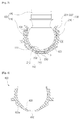
- FIG. 1 is a cross-sectional view illustrating a configuration of a conventional ball joint.
- the ball joint generally includes a ball stud (10) serving as a spheroid joint, a ball seat (20) which surrounds the ball stud (10) to protect the ball stud (10) and controls a friction force acting between the ball stud (10) and a socket (40), the socket (40) in which the ball stud (10) and the ball seat (20) are mounted, a plug (30) which seals the ball stud (10) to prevent a downward movement of the ball stud (10) under the socket (40) by a compressive load, and a dustcover (60) which covers an upper portion of the socket (40) to prevent dust from entering the ball stud (10), and caulking is performed on a lower end portion of the socket (40) and the ball joint is pressed on and inserted into a knuckle or arm to be assembled.
- a ball stud (10) serving as a spheroid joint
- a ball seat (20) which surrounds the ball stud (10) to protect the ball stud (10) and controls a friction force acting between
- the ball joint is provided with a plug (30) on a lower end of the socket (40) as well as the dustcover (60) for sealing.
- the ball stud (10), the ball seat (20), and the plug (30) are inserted into the inside of the socket (40) and coupled with each other by assembling the separately processed ball stud (10) and the ball seat (20), inserting the assembled ball stud (10) and ball seat (20) into the socket (40), covering a lower opening of the socket (40) by the plug (30), and caulking a lower end portion of the socket (40).
- the ball seat (20) is manufactured separately and then is assembled in the socket (40) using a complex assembly process such as caulking, etc., the productivity thereof can be lowered.
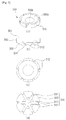
- FIG. 2A is a view illustrating a ball stud processed by machining
- FIG. 2B is a view illustrating a ball stud manufactured by welding.
- the ball stud (10) is provided with a stud portion (12) and a spherical head portion (13), and a portion of the spherical head portion (13) in contact with a ball seat is provided with a spherical surface.
- the spherical head portion (13) is formed to have the spherical surface by machining.
- a protruding portion is formed to have a vertex (13a) at the center of a lower end portion of the spherical head portion (13), thereby generating an interference with an inner side surface of the ball seat formed by injection molding, which influences on the quality of a product, and additionally requiring performing a separate treatment process to remove the vertex (13a).
- welding and coupling are performed on a welding portion (12a) of the stud portion (12) and a welding portion (13b) of the spherical head portion (13) having a spherical surface.
- a shear load acts on the welding portions
- cracks are generated in the welding portions by a shearing action, and thus a welding-type ball stud can be used for only some products subject only to a low shear load.
- the above described problems occur, and even when the ball stud is manufactured without the aspherical surface, after the ball seat is formed by injection molding, the ball seat contacts the spherical surface of the spherical head portion throughout, thereby generating an excessive torque while rotating the ball joint.
- the dustcover (60) is coupled with an upper end portion of the socket (40). Since a dustcover coupling portion in a groove shape should be formed in the socket (40) for coupling the dustcover (60) using a separate process, many processes are needed for processing the socket (40).
- the present invention is directed to providing a ball joint capable of increasing productivity by simplifying a manufacturing process for forming a ball seat on a ball stud having a spherical head portion by injection molding, and a method of manufacturing the same.
- One aspect of the present invention provides a ball joint including a ball stud (100) provided with a spherical head portion (110), a ball seat (200) configured to surround an outer circumferential surface of the spherical head portion (110) so that the ball stud (100) is movable within an operating angle range, a cap (300) configured to cover the spherical head portion (110) so that a sealed space is formed between the cap (300) and the outer circumferential surface of the spherical head portion (110), and a socket (400) having an inner space into which the spherical head portion (110), the ball seat (200), and the cap (300) are inserted.
- An aspherical surface (111) may be formed in the spherical head portion (110) and the cap (300) is formed to cover the aspherical surface (111).
- the sealed space may be formed between an upper groove formed in an upper surface of the cap (300) and the aspherical surface (111).
- the spherical head portion (110) may have a spherical surface, and the sealed space may be formed between a space between the spherical head portion (110) and the upper groove having a curvature greater than that of the spherical head portion (110) and formed in the upper surface of the cap (300).
- the upper groove may be provided with a first upper groove (300a) having a curvature the same as that of the spherical head portion (110) and a second upper groove (300b) having a curvature greater than that of the spherical head portion (110).
- the socket (400) may be provided with an inlet (410) through which the ball seat (200) is formed by injection molding.
- a cap mounting portion (420) may be formed on an inner circumferential surface of the socket (400) provided with the inlet (410) so that the cap (300) is mounted thereon.
- An outer circumferential surface (301) of the cap (300) may be provided to communicate with the inlet (410) so as to form a flow path (310) through which solution flows, while forming the ball seat (200) by injection molding.
- the flow path (310) may be provided with an inlet groove (311) formed in a lower surface (304) of the cap (300) to be close to the inlet (410) and diffusion paths (312) formed around the inlet groove (311) to communicate with a hollow portion, a space between the outer circumferential surface of the spherical head portion (110) and an inner circumferential surface of the socket (400), while forming the ball seat (200) by injection molding.
- a connection path (313) may be formed to connect the diffusion paths (312).
- the ball seat (200) may be provided with a seat portion (210) configured to surround the spherical head portion (110) and a cover coupling portion (220) connected to and formed on the seat portion (210) to be coupled with a dustcover.
- the cover coupling portion (220) may be formed to surround an outer circumferential surface of an end portion of the socket (400) and is provided with a coupling groove (221) to which the dustcover is coupled.
- Another aspect of the present invention provides a method of manufacturing a ball joint including a ball stud (100) having one end provided with a spherical head portion (110), a ball seat (200) which surrounds an outer circumferential surface of the spherical head portion (110) so that the ball stud (100) is movable within an operating angle range, and a socket (400) having an inner space into which the spherical head portion (110) and the ball seat (200) are inserted, and the method includes a) positioning the ball stud (100) so that a cap (300) covers the spherical head portion (110) to form a sealed space between the cap (300) and the spherical head portion (110), and a hollow portion formed between the outer circumferential surface of the spherical head portion (110) and an inner circumferential surface of the socket (400) has a shape of the ball seat (200), b) positioning a mold configured to cover the hollow portion so that the shape of the ball seat (200) is formed
- a spherical head portion of a ball stud is covered by a cap for a cover, and then a ball seat is formed by injection molding, thereby a manufacturing process of a ball joint can be simplified, the cost can be reduced, and the productivity can be improved.
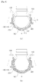
- FIG. 3 is a cross-sectional view illustrating a ball joint according to one embodiment of the present invention
- FIG. 4 is a cross-sectional view illustrating a socket according to one embodiment of the present invention.
- the ball joint according to the embodiment of the present invention includes a ball stud 100 having one end provided with a spherical head portion 110 in which an aspherical surface 111 is formed, a ball seat 200 configured to surround an outer circumferential surface of the spherical head portion 110 so that the ball stud 100 is movable within an operating angle range, a cap 300 configured to cover an upper surface of the aspherical surface 111 so that a sealed space is formed between the cap 300 and the aspherical surface 111 of the spherical head portion 110, and a socket 400 having an inner space into which the spherical head portion 110, the ball seat 200, and the cap 300 are inserted.
- the ball stud 100 is provided with the spherical head portion 110 having one end portion provided with the aspherical surface 111 and a stud portion 120.
- the aspherical surface 111 is a portion having a planar shape, and an area thereof in contact the with ball seat 200 varies based on the size of the aspherical surface 111, and thus a torque generated between the aspherical surface 111 and the ball seat 200 may be controlled by suitably setting the size of the aspherical surface 111.
- the ball seat 200 is formed by injection molding.
- a hollow portion in which the ball seat 200 is formed is formed by fixing the ball stud 100, the cap 300, and the socket 400 at predetermined positions and a melting synthetic resin flows into the hollow portion to perform injection molding, the ball joint may be manufactured by a simple manufacturing process.
- the ball seat 200 is provided with a seat portion 210 configured to surround the spherical head portion 110 and a cover coupling portion 220 connected to and formed on the seat portion 210 to be coupled with a dustcover 60.
- the seat portion 210 has a spherical surface so that the spherical head portion 110 may rotate on an inner circumferential surface of the spherical surface.
- the cover coupling portion 220 is formed to surround an outer circumferential surface of an upper end portion 430 of the socket 400 and is provided with a coupling groove 221 to which the dustcover is coupled. As described above, since the cover coupling portion 220 is integrally provided with the ball seat 200 by the injection molding, there is no need for the cover coupling portion on the socket made by using a conventional process separately, and thus a manufacturing process can be simplified.
- the ball seat 200 is provided with a protruding portion 230 formed by filling a space having an inlet 410 of the socket 400 with a synthetic resin solution, through which the synthetic resin solution flows during injection molding, and a connection portion 240 formed by filling a flow path 310 of the cap 300 with the synthetic resin solution.
- the connection portion 240 is provided with a first connection portion 241 formed by an inclined portion of a diffusion path 312 and a second connection portion 242 formed on an end portion of the first connection portion 241 in an upward direction.
- the protruding portion 230 and the connection portion 240 are portions not in contact with the spherical head portion 110 of the ball stud 100 and are portions formed by a flow path of the synthetic resin solution when the ball seat 200 is formed by the injection molding.
- the cap 300 is for forming a sealed space A by covering the aspherical surface 111 of the spherical head portion 110 of the ball stud 100 during injection molding and, for example, may use a synthetic resin material or another material other than the synthetic resin material.
- a synthetic resin material or another material other than the synthetic resin material.
- an area in which the outer circumferential surface of the spherical head portion 110 is in contact with an inner circumferential surface of the seat portion 210 may be controlled, and thus a suitable torque can be set.
- the socket 400 is provided with a body 400a configured to surround an inner space at which the ball seat 200 and the spherical head portion 110 are positioned, an inlet 410 formed on a lower end portion of the body 400a so that the melting synthetic resin flows into the inlet 410 when the ball seat 200 is formed by the injection molding, and a cap mounting portion 420 formed at a higher level than the inlet 410 and configured for mounting the cap 300.
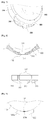
- FIG. 5 is a view illustrating a cap according to one embodiment of the present invention
- FIG. 5A is a perspective view
- FIG. 5B is a front view
- FIG. 5C is a plan view
- FIG. 5D is a bottom view.
- the cap 300 forms a sealed space A between the cap 300 and the aspherical surface 111 of the spherical head portion 110 of the ball stud 100 and blocks a synthetic resin solution flowing into the sealed space A during injection molding.
- the cap 300 is provided with upper grooves 300a and 300b concavely formed in an upper surface 301 facing the aspherical surface 111 to form the sealed space A, and the flow path 310, a path through which the synthetic resin solution flows during the injection molding, formed in an outer side surface 302, an inclined surface 303, and a lower surface 304.
- the upper grooves 300a and 300b may be provided with a first upper groove 300a having a curvature the same as that of the spherical surface of the spherical head portion 110 and a second upper groove 300b having a curvature greater than that of the spherical surface of the spherical head portion 110, and in this case, the sealed space A is provided with a space between the aspherical surface 111 and the second upper groove 300b.
- the flow path 310 is provided with an inlet groove 311, through which a synthetic resin solution flows, formed so that the lower surface 304 is dug to communicate with the inlet 410 of the socket 400 and diffusion paths 312 in which a path is formed around the inlet groove 311 to communicate with a hollow portion which is a space between the outer circumferential surface of the spherical head portion 110 and the inner circumferential surface of the socket 400 when the ball seat 200 is formed by the injection molding.
- the synthetic resin solution which flowed into the inlet 410 of the socket 400 during the injection molding flows into the inlet groove 311 and then flows uniformly along the diffusion paths 312, thereby the synthetic resin solution fills the hollow portion uniformly.
- the outer side surface 302, the inclined surface 303, and the lower surface 304 are in contact with an inner side surface of the cap mounting portion 420 of the socket 400, and the inlet 410 of the socket 400 and the hollow portion are communicated with each other through the flow path 310.
- FIG. 6 is a view illustrating a process of manufacturing a ball joint according to one embodiment of the present invention
- FIG. 7 is a perspective view illustrating an appearance of a ball seat manufactured by one embodiment of the present invention.
- the ball stud 100 having one end provided with the spherical head portion 110 in which the aspherical surface 111 is formed is provided, the cap 300 is positioned to cover the aspherical surface 111 so that the sealed space A is formed between the cap 300 and the aspherical surface 111, and the socket 400 is positioned to form a hollow portion B having a shape of the ball seat 200 between the socket 400 and the outer circumferential surface of the the spherical head portion 110.
- the cap 300 is positioned on the cap mounting portion 420 of the socket 400.
- a mold 500 configured to cover the hollow portion B is positioned so that the shape of the ball seat 200 is formed.
- FIG. 7 illustrates a shape when the ball seat 200 is formed completely.
- FIG. 8 is a view illustrating a cap according to another embodiment of the present invention.
- connection paths 313 configured to connect the adjacent diffusion paths 312 to each other.
- a synthetic resin solution flows from the inlet groove 311 to the diffusion paths 312 during injection molding, and some of the solution, which flowed into the diffusion paths 312, flows into the connection path 313 to form a part of the body of the ball seat 200.
- the synthetic resin solution uniformly flows into the hollow portion A through the connection paths 313 during the injection molding.
- FIG. 9 is a view when a spherical head portion of a spherical surface of a ball joint according to another embodiment of the present invention is covered by the cap.
- An upper groove formed in an upper surface of a cap 300 is provided with a first upper groove 300a having a curvature the same as that of a spherical head portion 110 and a second upper groove 300b having a curvature greater than that of the spherical head portion 110, and a sealed space is formed between the second upper groove 300b and an outer circumferential surface of the spherical head portion 110.
- the present invention relates to a ball joint including a ball seat and a method of manufacturing the same, a manufacturing process thereof is simplified by forming a ball stud having a spherical head portion together with a ball seat by injection molding, and thus the productivity thereof can be improved.
Landscapes
- Engineering & Computer Science (AREA)
- General Engineering & Computer Science (AREA)
- Mechanical Engineering (AREA)
- Pivots And Pivotal Connections (AREA)
Applications Claiming Priority (1)
| Application Number | Priority Date | Filing Date | Title |
|---|---|---|---|
| PCT/KR2013/006374 WO2015008879A1 (ko) | 2013-07-17 | 2013-07-17 | 볼 조인트 및 그 제조방법 |
Publications (3)
| Publication Number | Publication Date |
|---|---|
| EP3023652A1 true EP3023652A1 (de) | 2016-05-25 |
| EP3023652A4 EP3023652A4 (de) | 2017-03-08 |
| EP3023652B1 EP3023652B1 (de) | 2018-12-26 |
Family
ID=52346315
Family Applications (1)
| Application Number | Title | Priority Date | Filing Date |
|---|---|---|---|
| EP13889731.9A Active EP3023652B1 (de) | 2013-07-17 | 2013-07-17 | Kugelgelenk |
Country Status (6)
| Country | Link |
|---|---|
| US (1) | US10066661B2 (de) |
| EP (1) | EP3023652B1 (de) |
| JP (1) | JP6171099B2 (de) |
| CN (1) | CN105378305B (de) |
| MX (1) | MX368303B (de) |
| WO (1) | WO2015008879A1 (de) |
Cited By (2)
| Publication number | Priority date | Publication date | Assignee | Title |
|---|---|---|---|---|
| WO2018158030A1 (de) | 2017-03-03 | 2018-09-07 | Zf Friedrichshafen Ag | Einleger für ein kugelgelenk in einem kraftfahrzeug, kugelgelenk oder lenker mit einem solchen einleger und verfahren zum herstellen eines solchen einlegers, eines solchen kugelgelenks oder eines solchen lenkers |
| DE102017206706A1 (de) | 2017-04-20 | 2018-10-25 | Zf Friedrichshafen Ag | Verfahren zur Herstellung eines Kugelgelenks |
Families Citing this family (9)
| Publication number | Priority date | Publication date | Assignee | Title |
|---|---|---|---|---|
| KR101814612B1 (ko) * | 2016-01-18 | 2018-01-04 | 주식회사 일진 | 볼 조인트 및 그 제작 방법 |
| KR101715702B1 (ko) * | 2016-09-23 | 2017-03-13 | 주식회사 센트랄 | 소켓 방수를 위한 씰런트 기밀구조를 가지는 볼조인트 |
| KR101934876B1 (ko) * | 2016-11-11 | 2019-04-05 | 주식회사 일진 | 볼 조인트 |
| US10711830B2 (en) | 2017-03-01 | 2020-07-14 | Federal-Mogul Motorparts Llc | Socket assembly |
| DE102017108982B4 (de) * | 2017-04-26 | 2024-02-15 | Benteler Automobiltechnik Gmbh | Radlenker mit einem Kugelgelenk |
| EP3669092B1 (de) | 2017-08-16 | 2022-06-22 | Multimatic, Inc. | Kugelgelenk mit spritzgegossenem lager |
| DE102018220954B4 (de) * | 2018-12-04 | 2020-06-25 | Zf Friedrichshafen Ag | Kugelgelenk |
| DE102020209477B3 (de) | 2020-07-28 | 2021-12-09 | Zf Friedrichshafen Ag | Verschlusselement für ein Kugelgelenk sowie Kugelgelenk für ein Fahrwerk eines Fahrzeugs |
| CN112196888B (zh) * | 2020-09-22 | 2022-04-22 | 江西大杰科技产业有限公司 | 一种汽车球头防尘罩 |
Family Cites Families (23)
| Publication number | Priority date | Publication date | Assignee | Title |
|---|---|---|---|---|
| JPS57203135A (en) | 1981-06-10 | 1982-12-13 | Toshiba Corp | Data transfer system |
| JPS6139843Y2 (de) * | 1981-06-23 | 1986-11-14 | ||
| US4478531A (en) * | 1982-10-12 | 1984-10-23 | Moog Automotive, Inc. | Rack and pinion ball joint assembly |
| JP3059356B2 (ja) * | 1994-09-30 | 2000-07-04 | テイエチケー株式会社 | ボールジョイント |
| KR0131652Y1 (ko) * | 1994-12-30 | 1999-05-01 | 전성원 | 자동차 현가장치의 볼 조인트 |
| JPH10131942A (ja) * | 1996-10-25 | 1998-05-22 | Otix:Kk | ボールジョイント |
| JPH1113740A (ja) * | 1997-06-26 | 1999-01-22 | Chuo Spring Co Ltd | ボールジョイント |
| DE29714339U1 (de) * | 1997-08-13 | 1998-12-17 | Sachsenring Automobiltechnik AG, 08058 Zwickau | Kugelgelenk |
| JP4365481B2 (ja) * | 1999-06-09 | 2009-11-18 | 株式会社ソミック石川 | 自在継手装置およびその製造方法 |
| JP2003094129A (ja) | 2001-09-25 | 2003-04-02 | Musashi Seimitsu Ind Co Ltd | ロッドの連結構造及びそのかしめ成形装置 |
| DE10227014B4 (de) * | 2002-06-17 | 2008-07-10 | ZF Lemförder GmbH | Zwei-Komponenten Lagerschale für ein umspritztes Kugelgelenk |
| JP3862669B2 (ja) * | 2003-04-16 | 2006-12-27 | Thk株式会社 | 球面軸受の製造方法 |
| DE202004012604U1 (de) * | 2004-08-11 | 2004-12-23 | Trw Automotive Gmbh | Kugelgelenk |
| JP2007230507A (ja) | 2006-03-03 | 2007-09-13 | Honda Motor Co Ltd | 車両の懸架装置及び該懸架装置に使用するボールスタッド |
| DE112007002148B4 (de) * | 2006-09-27 | 2020-07-02 | Thk Co., Ltd. | Herstellungsverfahren für ein Kugelgelenklager |
| DE102007001933A1 (de) * | 2007-01-12 | 2008-07-17 | Trw Automotive Gmbh | Kugelgelenk |
| KR100906413B1 (ko) | 2007-09-19 | 2009-07-09 | 주식회사 센트랄 | 볼 조인트 코킹부에 러버 커버를 적용한 볼 조인트 |
| US8342769B2 (en) * | 2009-02-13 | 2013-01-01 | Elterman James J | Pivot socket with cartridge bearing and vehicle steering linkage therewith |
| KR101069910B1 (ko) | 2009-08-10 | 2011-10-05 | 주식회사 일진 | 볼 조인트 및 그 제조 방법 |
| WO2011019108A1 (ko) * | 2009-08-10 | 2011-02-17 | 주식회사 일진 | 볼조인트 구조 및 이의 제조방법 |
| JP5721774B2 (ja) * | 2013-05-29 | 2015-05-20 | Thk株式会社 | ボールジョイント |
| KR101704011B1 (ko) * | 2015-07-21 | 2017-02-27 | 주식회사 프라이맥스 | 볼 조인트, 볼 조인트 제조 장치 및 볼 조인트 제조 방법 |
| US10473147B2 (en) * | 2016-03-15 | 2019-11-12 | Federal-Mogul Motorparts Llc | Socket assembly and method of making a socket assembly |
-
2013
- 2013-07-17 US US14/903,946 patent/US10066661B2/en active Active
- 2013-07-17 JP JP2016527901A patent/JP6171099B2/ja active Active
- 2013-07-17 EP EP13889731.9A patent/EP3023652B1/de active Active
- 2013-07-17 CN CN201380078321.7A patent/CN105378305B/zh active Active
- 2013-07-17 MX MX2016000563A patent/MX368303B/es active IP Right Grant
- 2013-07-17 WO PCT/KR2013/006374 patent/WO2015008879A1/ko not_active Ceased
Non-Patent Citations (1)
| Title |
|---|
| See references of WO2015008879A1 * |
Cited By (6)
| Publication number | Priority date | Publication date | Assignee | Title |
|---|---|---|---|---|
| WO2018158030A1 (de) | 2017-03-03 | 2018-09-07 | Zf Friedrichshafen Ag | Einleger für ein kugelgelenk in einem kraftfahrzeug, kugelgelenk oder lenker mit einem solchen einleger und verfahren zum herstellen eines solchen einlegers, eines solchen kugelgelenks oder eines solchen lenkers |
| US11713782B2 (en) | 2017-03-03 | 2023-08-01 | Zf Friedrichshafen Ag | Insert for a ball joint in a motor vehicle, ball joint or link having an insert of this type, and method for producing an insert of this type, a ball joint of this type or a link of this type |
| DE102017206706A1 (de) | 2017-04-20 | 2018-10-25 | Zf Friedrichshafen Ag | Verfahren zur Herstellung eines Kugelgelenks |
| WO2018192728A1 (de) | 2017-04-20 | 2018-10-25 | Zf Friedrichshafen Ag | Verfahren zur herstellung eines kugelgelenks |
| DE102017206706B4 (de) | 2017-04-20 | 2019-03-14 | Zf Friedrichshafen Ag | Verfahren zur Herstellung eines Kugelgelenks |
| US11078952B2 (en) | 2017-04-20 | 2021-08-03 | Zf Friedrichshafen Ag | Method for producing a ball joint |
Also Published As
| Publication number | Publication date |
|---|---|
| CN105378305B (zh) | 2018-05-11 |
| MX2016000563A (es) | 2016-08-11 |
| US20160160907A1 (en) | 2016-06-09 |
| JP6171099B2 (ja) | 2017-07-26 |
| WO2015008879A1 (ko) | 2015-01-22 |
| MX368303B (es) | 2019-09-27 |
| US10066661B2 (en) | 2018-09-04 |
| JP2016525199A (ja) | 2016-08-22 |
| EP3023652B1 (de) | 2018-12-26 |
| EP3023652A4 (de) | 2017-03-08 |
| CN105378305A (zh) | 2016-03-02 |
Similar Documents
| Publication | Publication Date | Title |
|---|---|---|
| EP3023652B1 (de) | Kugelgelenk | |
| KR101357452B1 (ko) | 볼 조인트 및 그 제조방법 | |
| US9546679B2 (en) | Bearing seat for a ball joint and a ball joint | |
| CN105209771B (zh) | 球接头 | |
| KR102129017B1 (ko) | 볼 조인트 및 이것을 사용한 스태빌라이저 링크 | |
| CN102985708A (zh) | 球形接头及球形接头的制造方法 | |
| KR101288203B1 (ko) | 섀시 부품의 제조 방법 | |
| JP6043093B2 (ja) | ボールジョイント | |
| US20190291525A1 (en) | Ball joint and manufacturing method therefor | |
| JP6214463B2 (ja) | ボールジョイント | |
| CN104165182A (zh) | 球节和机动车控制杆 | |
| EP3669092B1 (de) | Kugelgelenk mit spritzgegossenem lager | |
| US7090425B2 (en) | Balljoint | |
| US20170129040A1 (en) | Method for producing a chassis component | |
| CN109314023A (zh) | 具有带凹口端部分的中空熔断器主体 | |
| KR20170098007A (ko) | 볼조인트 | |
| KR101002985B1 (ko) | 자동차용 필로우 볼 조인트 | |
| CN106439032A (zh) | 具有连接插入件的密封件 | |
| CN110382884B (zh) | 用于机动车中的球窝关节的嵌入件以及用于制造这种嵌入件的方法 | |
| JP2018025202A (ja) | ダストカバー及びボールジョイント | |
| JP6752041B2 (ja) | ボールジョイント及びそのベアリングシート | |
| TWI613062B (zh) | 樹脂成形品之熔黏方法 | |
| KR101048887B1 (ko) | 섀시 부품의 제조 방법 | |
| JP7181149B2 (ja) | ボールジョイントのボールシート固定構造及びボールシート固定方法 | |
| JP2007132506A (ja) | ボールジョイント |
Legal Events
| Date | Code | Title | Description |
|---|---|---|---|
| PUAI | Public reference made under article 153(3) epc to a published international application that has entered the european phase |
Free format text: ORIGINAL CODE: 0009012 |
|
| 17P | Request for examination filed |
Effective date: 20160108 |
|
| AK | Designated contracting states |
Kind code of ref document: A1 Designated state(s): AL AT BE BG CH CY CZ DE DK EE ES FI FR GB GR HR HU IE IS IT LI LT LU LV MC MK MT NL NO PL PT RO RS SE SI SK SM TR |
|
| AX | Request for extension of the european patent |
Extension state: BA ME |
|
| RIN1 | Information on inventor provided before grant (corrected) |
Inventor name: KIM, YOUNG KI |
|
| DAX | Request for extension of the european patent (deleted) | ||
| A4 | Supplementary search report drawn up and despatched |
Effective date: 20170206 |
|
| RIC1 | Information provided on ipc code assigned before grant |
Ipc: F16C 11/06 20060101AFI20170131BHEP |
|
| GRAP | Despatch of communication of intention to grant a patent |
Free format text: ORIGINAL CODE: EPIDOSNIGR1 |
|
| STAA | Information on the status of an ep patent application or granted ep patent |
Free format text: STATUS: GRANT OF PATENT IS INTENDED |
|
| INTG | Intention to grant announced |
Effective date: 20180928 |
|
| GRAS | Grant fee paid |
Free format text: ORIGINAL CODE: EPIDOSNIGR3 |
|
| GRAA | (expected) grant |
Free format text: ORIGINAL CODE: 0009210 |
|
| STAA | Information on the status of an ep patent application or granted ep patent |
Free format text: STATUS: THE PATENT HAS BEEN GRANTED |
|
| AK | Designated contracting states |
Kind code of ref document: B1 Designated state(s): AL AT BE BG CH CY CZ DE DK EE ES FI FR GB GR HR HU IE IS IT LI LT LU LV MC MK MT NL NO PL PT RO RS SE SI SK SM TR |
|
| REG | Reference to a national code |
Ref country code: GB Ref legal event code: FG4D |
|
| REG | Reference to a national code |
Ref country code: CH Ref legal event code: EP |
|
| REG | Reference to a national code |
Ref country code: AT Ref legal event code: REF Ref document number: 1081830 Country of ref document: AT Kind code of ref document: T Effective date: 20190115 |
|
| REG | Reference to a national code |
Ref country code: DE Ref legal event code: R096 Ref document number: 602013049000 Country of ref document: DE |
|
| REG | Reference to a national code |
Ref country code: IE Ref legal event code: FG4D |
|
| REG | Reference to a national code |
Ref country code: SE Ref legal event code: TRGR |
|
| PG25 | Lapsed in a contracting state [announced via postgrant information from national office to epo] |
Ref country code: FI Free format text: LAPSE BECAUSE OF FAILURE TO SUBMIT A TRANSLATION OF THE DESCRIPTION OR TO PAY THE FEE WITHIN THE PRESCRIBED TIME-LIMIT Effective date: 20181226 Ref country code: BG Free format text: LAPSE BECAUSE OF FAILURE TO SUBMIT A TRANSLATION OF THE DESCRIPTION OR TO PAY THE FEE WITHIN THE PRESCRIBED TIME-LIMIT Effective date: 20190326 Ref country code: NO Free format text: LAPSE BECAUSE OF FAILURE TO SUBMIT A TRANSLATION OF THE DESCRIPTION OR TO PAY THE FEE WITHIN THE PRESCRIBED TIME-LIMIT Effective date: 20190326 Ref country code: LT Free format text: LAPSE BECAUSE OF FAILURE TO SUBMIT A TRANSLATION OF THE DESCRIPTION OR TO PAY THE FEE WITHIN THE PRESCRIBED TIME-LIMIT Effective date: 20181226 Ref country code: LV Free format text: LAPSE BECAUSE OF FAILURE TO SUBMIT A TRANSLATION OF THE DESCRIPTION OR TO PAY THE FEE WITHIN THE PRESCRIBED TIME-LIMIT Effective date: 20181226 Ref country code: HR Free format text: LAPSE BECAUSE OF FAILURE TO SUBMIT A TRANSLATION OF THE DESCRIPTION OR TO PAY THE FEE WITHIN THE PRESCRIBED TIME-LIMIT Effective date: 20181226 |
|
| REG | Reference to a national code |
Ref country code: NL Ref legal event code: MP Effective date: 20181226 |
|
| REG | Reference to a national code |
Ref country code: LT Ref legal event code: MG4D |
|
| PG25 | Lapsed in a contracting state [announced via postgrant information from national office to epo] |
Ref country code: AL Free format text: LAPSE BECAUSE OF FAILURE TO SUBMIT A TRANSLATION OF THE DESCRIPTION OR TO PAY THE FEE WITHIN THE PRESCRIBED TIME-LIMIT Effective date: 20181226 Ref country code: GR Free format text: LAPSE BECAUSE OF FAILURE TO SUBMIT A TRANSLATION OF THE DESCRIPTION OR TO PAY THE FEE WITHIN THE PRESCRIBED TIME-LIMIT Effective date: 20190327 Ref country code: RS Free format text: LAPSE BECAUSE OF FAILURE TO SUBMIT A TRANSLATION OF THE DESCRIPTION OR TO PAY THE FEE WITHIN THE PRESCRIBED TIME-LIMIT Effective date: 20181226 |
|
| REG | Reference to a national code |
Ref country code: AT Ref legal event code: MK05 Ref document number: 1081830 Country of ref document: AT Kind code of ref document: T Effective date: 20181226 |
|
| PG25 | Lapsed in a contracting state [announced via postgrant information from national office to epo] |
Ref country code: NL Free format text: LAPSE BECAUSE OF FAILURE TO SUBMIT A TRANSLATION OF THE DESCRIPTION OR TO PAY THE FEE WITHIN THE PRESCRIBED TIME-LIMIT Effective date: 20181226 |
|
| PG25 | Lapsed in a contracting state [announced via postgrant information from national office to epo] |
Ref country code: PL Free format text: LAPSE BECAUSE OF FAILURE TO SUBMIT A TRANSLATION OF THE DESCRIPTION OR TO PAY THE FEE WITHIN THE PRESCRIBED TIME-LIMIT Effective date: 20181226 Ref country code: ES Free format text: LAPSE BECAUSE OF FAILURE TO SUBMIT A TRANSLATION OF THE DESCRIPTION OR TO PAY THE FEE WITHIN THE PRESCRIBED TIME-LIMIT Effective date: 20181226 Ref country code: CZ Free format text: LAPSE BECAUSE OF FAILURE TO SUBMIT A TRANSLATION OF THE DESCRIPTION OR TO PAY THE FEE WITHIN THE PRESCRIBED TIME-LIMIT Effective date: 20181226 Ref country code: PT Free format text: LAPSE BECAUSE OF FAILURE TO SUBMIT A TRANSLATION OF THE DESCRIPTION OR TO PAY THE FEE WITHIN THE PRESCRIBED TIME-LIMIT Effective date: 20190426 |
|
| PG25 | Lapsed in a contracting state [announced via postgrant information from national office to epo] |
Ref country code: EE Free format text: LAPSE BECAUSE OF FAILURE TO SUBMIT A TRANSLATION OF THE DESCRIPTION OR TO PAY THE FEE WITHIN THE PRESCRIBED TIME-LIMIT Effective date: 20181226 Ref country code: SM Free format text: LAPSE BECAUSE OF FAILURE TO SUBMIT A TRANSLATION OF THE DESCRIPTION OR TO PAY THE FEE WITHIN THE PRESCRIBED TIME-LIMIT Effective date: 20181226 Ref country code: IS Free format text: LAPSE BECAUSE OF FAILURE TO SUBMIT A TRANSLATION OF THE DESCRIPTION OR TO PAY THE FEE WITHIN THE PRESCRIBED TIME-LIMIT Effective date: 20190426 Ref country code: RO Free format text: LAPSE BECAUSE OF FAILURE TO SUBMIT A TRANSLATION OF THE DESCRIPTION OR TO PAY THE FEE WITHIN THE PRESCRIBED TIME-LIMIT Effective date: 20181226 Ref country code: SK Free format text: LAPSE BECAUSE OF FAILURE TO SUBMIT A TRANSLATION OF THE DESCRIPTION OR TO PAY THE FEE WITHIN THE PRESCRIBED TIME-LIMIT Effective date: 20181226 |
|
| REG | Reference to a national code |
Ref country code: DE Ref legal event code: R097 Ref document number: 602013049000 Country of ref document: DE |
|
| PG25 | Lapsed in a contracting state [announced via postgrant information from national office to epo] |
Ref country code: DK Free format text: LAPSE BECAUSE OF FAILURE TO SUBMIT A TRANSLATION OF THE DESCRIPTION OR TO PAY THE FEE WITHIN THE PRESCRIBED TIME-LIMIT Effective date: 20181226 Ref country code: AT Free format text: LAPSE BECAUSE OF FAILURE TO SUBMIT A TRANSLATION OF THE DESCRIPTION OR TO PAY THE FEE WITHIN THE PRESCRIBED TIME-LIMIT Effective date: 20181226 |
|
| PLBE | No opposition filed within time limit |
Free format text: ORIGINAL CODE: 0009261 |
|
| STAA | Information on the status of an ep patent application or granted ep patent |
Free format text: STATUS: NO OPPOSITION FILED WITHIN TIME LIMIT |
|
| 26N | No opposition filed |
Effective date: 20190927 |
|
| PG25 | Lapsed in a contracting state [announced via postgrant information from national office to epo] |
Ref country code: SI Free format text: LAPSE BECAUSE OF FAILURE TO SUBMIT A TRANSLATION OF THE DESCRIPTION OR TO PAY THE FEE WITHIN THE PRESCRIBED TIME-LIMIT Effective date: 20181226 Ref country code: MC Free format text: LAPSE BECAUSE OF FAILURE TO SUBMIT A TRANSLATION OF THE DESCRIPTION OR TO PAY THE FEE WITHIN THE PRESCRIBED TIME-LIMIT Effective date: 20181226 |
|
| REG | Reference to a national code |
Ref country code: CH Ref legal event code: PL |
|
| PG25 | Lapsed in a contracting state [announced via postgrant information from national office to epo] |
Ref country code: TR Free format text: LAPSE BECAUSE OF FAILURE TO SUBMIT A TRANSLATION OF THE DESCRIPTION OR TO PAY THE FEE WITHIN THE PRESCRIBED TIME-LIMIT Effective date: 20181226 |
|
| REG | Reference to a national code |
Ref country code: BE Ref legal event code: MM Effective date: 20190731 |
|
| PG25 | Lapsed in a contracting state [announced via postgrant information from national office to epo] |
Ref country code: BE Free format text: LAPSE BECAUSE OF NON-PAYMENT OF DUE FEES Effective date: 20190731 Ref country code: LI Free format text: LAPSE BECAUSE OF NON-PAYMENT OF DUE FEES Effective date: 20190731 Ref country code: LU Free format text: LAPSE BECAUSE OF NON-PAYMENT OF DUE FEES Effective date: 20190717 Ref country code: CH Free format text: LAPSE BECAUSE OF NON-PAYMENT OF DUE FEES Effective date: 20190731 |
|
| PG25 | Lapsed in a contracting state [announced via postgrant information from national office to epo] |
Ref country code: IE Free format text: LAPSE BECAUSE OF NON-PAYMENT OF DUE FEES Effective date: 20190717 |
|
| PGFP | Annual fee paid to national office [announced via postgrant information from national office to epo] |
Ref country code: FR Payment date: 20200623 Year of fee payment: 8 |
|
| PGFP | Annual fee paid to national office [announced via postgrant information from national office to epo] |
Ref country code: GB Payment date: 20200623 Year of fee payment: 8 |
|
| PGFP | Annual fee paid to national office [announced via postgrant information from national office to epo] |
Ref country code: IT Payment date: 20200721 Year of fee payment: 8 Ref country code: SE Payment date: 20200708 Year of fee payment: 8 |
|
| PG25 | Lapsed in a contracting state [announced via postgrant information from national office to epo] |
Ref country code: CY Free format text: LAPSE BECAUSE OF FAILURE TO SUBMIT A TRANSLATION OF THE DESCRIPTION OR TO PAY THE FEE WITHIN THE PRESCRIBED TIME-LIMIT Effective date: 20181226 |
|
| PG25 | Lapsed in a contracting state [announced via postgrant information from national office to epo] |
Ref country code: MT Free format text: LAPSE BECAUSE OF FAILURE TO SUBMIT A TRANSLATION OF THE DESCRIPTION OR TO PAY THE FEE WITHIN THE PRESCRIBED TIME-LIMIT Effective date: 20181226 Ref country code: HU Free format text: LAPSE BECAUSE OF FAILURE TO SUBMIT A TRANSLATION OF THE DESCRIPTION OR TO PAY THE FEE WITHIN THE PRESCRIBED TIME-LIMIT; INVALID AB INITIO Effective date: 20130717 |
|
| GBPC | Gb: european patent ceased through non-payment of renewal fee |
Effective date: 20210717 |
|
| PG25 | Lapsed in a contracting state [announced via postgrant information from national office to epo] |
Ref country code: GB Free format text: LAPSE BECAUSE OF NON-PAYMENT OF DUE FEES Effective date: 20210717 |
|
| PG25 | Lapsed in a contracting state [announced via postgrant information from national office to epo] |
Ref country code: SE Free format text: LAPSE BECAUSE OF NON-PAYMENT OF DUE FEES Effective date: 20210718 Ref country code: FR Free format text: LAPSE BECAUSE OF NON-PAYMENT OF DUE FEES Effective date: 20210731 |
|
| PG25 | Lapsed in a contracting state [announced via postgrant information from national office to epo] |
Ref country code: MK Free format text: LAPSE BECAUSE OF FAILURE TO SUBMIT A TRANSLATION OF THE DESCRIPTION OR TO PAY THE FEE WITHIN THE PRESCRIBED TIME-LIMIT Effective date: 20181226 |
|
| PG25 | Lapsed in a contracting state [announced via postgrant information from national office to epo] |
Ref country code: IT Free format text: LAPSE BECAUSE OF NON-PAYMENT OF DUE FEES Effective date: 20210717 |
|
| REG | Reference to a national code |
Ref country code: DE Ref legal event code: R081 Ref document number: 602013049000 Country of ref document: DE Owner name: CTR CO., LTD., CHANGWON-SI, KR Free format text: FORMER OWNER: CENTRAL CORPORATION, CHANGWON-SI, GYEONGSANGNAM-DO, KR |
|
| PGFP | Annual fee paid to national office [announced via postgrant information from national office to epo] |
Ref country code: DE Payment date: 20250729 Year of fee payment: 13 |