EP3023698A1 - Dispositif de determination d'un rapport de gradation, une turbine a gaz ou moteur d'aeronef comprenant un tel dispositif et son utilisation - Google Patents
Dispositif de determination d'un rapport de gradation, une turbine a gaz ou moteur d'aeronef comprenant un tel dispositif et son utilisation Download PDFInfo
- Publication number
- EP3023698A1 EP3023698A1 EP15195002.9A EP15195002A EP3023698A1 EP 3023698 A1 EP3023698 A1 EP 3023698A1 EP 15195002 A EP15195002 A EP 15195002A EP 3023698 A1 EP3023698 A1 EP 3023698A1
- Authority
- EP
- European Patent Office
- Prior art keywords
- ratio
- fuel
- staging
- turbine
- parameter
- Prior art date
- Legal status (The legal status is an assumption and is not a legal conclusion. Google has not performed a legal analysis and makes no representation as to the accuracy of the status listed.)
- Granted
Links
Images


Classifications
-
- F—MECHANICAL ENGINEERING; LIGHTING; HEATING; WEAPONS; BLASTING
- F23—COMBUSTION APPARATUS; COMBUSTION PROCESSES
- F23R—GENERATING COMBUSTION PRODUCTS OF HIGH PRESSURE OR HIGH VELOCITY, e.g. GAS-TURBINE COMBUSTION CHAMBERS
- F23R3/00—Continuous combustion chambers using liquid or gaseous fuel
- F23R3/28—Continuous combustion chambers using liquid or gaseous fuel characterised by the fuel supply
- F23R3/34—Feeding into different combustion zones
- F23R3/346—Feeding into different combustion zones for staged combustion
-
- F—MECHANICAL ENGINEERING; LIGHTING; HEATING; WEAPONS; BLASTING
- F02—COMBUSTION ENGINES; HOT-GAS OR COMBUSTION-PRODUCT ENGINE PLANTS
- F02C—GAS-TURBINE PLANTS; AIR INTAKES FOR JET-PROPULSION PLANTS; CONTROLLING FUEL SUPPLY IN AIR-BREATHING JET-PROPULSION PLANTS
- F02C7/00—Features, components parts, details or accessories, not provided for in, or of interest apart form groups F02C1/00 - F02C6/00; Air intakes for jet-propulsion plants
- F02C7/22—Fuel supply systems
- F02C7/228—Dividing fuel between various burners
-
- F—MECHANICAL ENGINEERING; LIGHTING; HEATING; WEAPONS; BLASTING
- F02—COMBUSTION ENGINES; HOT-GAS OR COMBUSTION-PRODUCT ENGINE PLANTS
- F02C—GAS-TURBINE PLANTS; AIR INTAKES FOR JET-PROPULSION PLANTS; CONTROLLING FUEL SUPPLY IN AIR-BREATHING JET-PROPULSION PLANTS
- F02C9/00—Controlling gas-turbine plants; Controlling fuel supply in air- breathing jet-propulsion plants
- F02C9/26—Control of fuel supply
- F02C9/28—Regulating systems responsive to plant or ambient parameters, e.g. temperature, pressure, rotor speed
-
- F—MECHANICAL ENGINEERING; LIGHTING; HEATING; WEAPONS; BLASTING
- F02—COMBUSTION ENGINES; HOT-GAS OR COMBUSTION-PRODUCT ENGINE PLANTS
- F02C—GAS-TURBINE PLANTS; AIR INTAKES FOR JET-PROPULSION PLANTS; CONTROLLING FUEL SUPPLY IN AIR-BREATHING JET-PROPULSION PLANTS
- F02C9/00—Controlling gas-turbine plants; Controlling fuel supply in air- breathing jet-propulsion plants
- F02C9/26—Control of fuel supply
- F02C9/32—Control of fuel supply characterised by throttling of fuel
- F02C9/34—Joint control of separate flows to main and auxiliary burners
-
- F—MECHANICAL ENGINEERING; LIGHTING; HEATING; WEAPONS; BLASTING
- F23—COMBUSTION APPARATUS; COMBUSTION PROCESSES
- F23R—GENERATING COMBUSTION PRODUCTS OF HIGH PRESSURE OR HIGH VELOCITY, e.g. GAS-TURBINE COMBUSTION CHAMBERS
- F23R3/00—Continuous combustion chambers using liquid or gaseous fuel
- F23R3/28—Continuous combustion chambers using liquid or gaseous fuel characterised by the fuel supply
- F23R3/34—Feeding into different combustion zones
-
- F—MECHANICAL ENGINEERING; LIGHTING; HEATING; WEAPONS; BLASTING
- F23—COMBUSTION APPARATUS; COMBUSTION PROCESSES
- F23N—REGULATING OR CONTROLLING COMBUSTION
- F23N2237/00—Controlling
- F23N2237/02—Controlling two or more burners
-
- Y—GENERAL TAGGING OF NEW TECHNOLOGICAL DEVELOPMENTS; GENERAL TAGGING OF CROSS-SECTIONAL TECHNOLOGIES SPANNING OVER SEVERAL SECTIONS OF THE IPC; TECHNICAL SUBJECTS COVERED BY FORMER USPC CROSS-REFERENCE ART COLLECTIONS [XRACs] AND DIGESTS
- Y02—TECHNOLOGIES OR APPLICATIONS FOR MITIGATION OR ADAPTATION AGAINST CLIMATE CHANGE
- Y02T—CLIMATE CHANGE MITIGATION TECHNOLOGIES RELATED TO TRANSPORTATION
- Y02T50/00—Aeronautics or air transport
- Y02T50/60—Efficient propulsion technologies, e.g. for aircraft
Definitions
- the invention relates to an apparatus for determining a staging ratio in at least one staged combustion chamber in a gas turbine or in an aircraft engine with the features of claim 1, a gas turbine or an aircraft engine with the features of claim 14 and a use therefor according to claim 15.
- stepped combustors are used, with pilot burners of the stepped combustor always being supplied with a minimum amount of fuel.
- Main burners of the stepped combustion chamber are only switched on at a higher required power.
- the ratio of the pilot fuel flow to the total fuel flow is called the staging ratio.
- a Stufungsventiliser Downstream of the total fuel quantity determining control valve unit is provided a Stufungsventiliser with which the total fuel mass flow to the pilot burner and the main burner is changeable divisible.
- the control valve unit and / or the Stufungsventiliser can be controlled by an engine controller, which applies the desired engine performance for the control of the Stufungsventiliser.
- Such a system is for example from the WO 95/17632 A1 or the EP 1 079 179 B1 known.
- a first adjusting device for determining a preselected required staging ratio for the stepped combustion chamber is provided, wherein this determination in dependence on the detection of a steady state or the detection of a transient state is feasible, the detection in particular due to a Brennschlingerstemperatur, a
- Turbine inlet temperature and / or a value for the fuel-air ratio is feasible
- the fuel-to-air ratio and combustor exit temperature may be calculated by synthesis methods, with other sensor values, such as those shown in FIG. Compressor outlet temperature and pressure or the total fuel mass flow can be used.
- Compressor outlet temperature and pressure or the total fuel mass flow can be used.
- a grading ratio is determined. This can then be e.g. be converted into a setpoint for the valve position via a table as a function of the total fuel flow. This valve position is then adjusted by a separate control valve unit.
- the calculated step ratio may correspond to the final step ratio, or may be used as a computational quantity to ultimately arrive at an end step ratio.
- a determination means for distinguishing the stationary state from the transient state is provided, wherein the differentiation can be carried out in particular on the basis of a temperature value representative of the staging ratio in the staged combustion chamber.
- An output of the determining means affects the position of the first adjusting device.
- a required staging ratio can be determined as a function of a smoke limit, wherein the respective smaller value of the preselected required staging ratio and the required staging ratio for the smoke limit can be determined as a first staging ratio parameter.
- the smoke limit may e.g. calculated as a function of the fuel-air ratio.
- the quenching limit is an important operating parameter, so that in one embodiment a second grading ratio parameter can be determined from the first grading ratio parameter and a required grading ratio for the quenching limit representative of the quenching limit of the flame in FIG the stepped combustion chamber, in particular representative of the lean extinction limit (WEX Lim), wherein in each case the greater value of the required staging ratio for the quench limit and the first Stufungsconceparameters is determined as the second Stufungslutterparameter.
- WEX Lim lean extinction limit
- the smoke emission and extinction limit are taken into account in determining the final staging ratio.
- the quenching limit has a higher priority, so that in the event of a conflict, e.g. Bad sensors or sensor failures and thus an inaccurately determined fuel / air ratio can cause more smoke is accepted before the engine fails.
- a second setting device for determining a third step ratio parameter as a function of at least one required step ratio can be determined as a function of a redundancy rule set, wherein the selection of a presetting of the second setting device is effected in particular as a function of the redundancy rule set.
- another embodiment has a third setting device for determining a fourth step ratio parameter as a function of at least one required step ratio for the consideration of turbine operating states, which is determinable as a function of a turbine operating parameter for characterizing abnormal operating states, in particular selecting a presetting of the third adjusting device in response to the turbine operating parameter for characterizing abnormal operating conditions.
- a turbine operating parameter may be abnormal operating conditions, e.g. characterizing turbine start-up, turbine re-ignition, water ingress, surge and / or combustion extinction.
- a required staging ratio for minimum fuel flow can be determined as a function of the total fuel flow, wherein the respectively greater value of the required staging ratio for minimum fuel flow or the fourth staging ratio parameter can be determined as a fifth staging ratio parameter.
- a required staging ratio may be determined to account for a stopband in dependence on parameters representative of a range of fuel flow ratios that are not adjustable due to hydrodynamic and / or thermal constraints is.
- certain gradation ratios due to hydrodynamic or thermal restrictions are not adjustable (Sperr Hoch, also called “keep-out zone", KOZ called), so that can be commanded only outside the restricted area.
- a required staging ratio for protection against fuel overpressure depending on the fuel pressure in the fuel system of the pilot burner can be determined, wherein the fifth Stufungs stapleparameter, the required staging ratio for the consideration of the stopband and the required staging ratio for protection against fuel overpressure in each case the smallest value sixth gradation ratio parameter can be determined.
- a required staging ratio for the fuel fill level of the injector can be determined as a function of the fuel fill level.
- the transition from a pure pilot mode to mixed mode requires filling the previously empty volumes of the main burner injectors. This process must be done in a controlled manner at a certain staging ratio, which is a compromise between fill duration, temporary thrust loss, and impact on compressor stability.
- a filling model predicts how long it will take to fill the main injectors. During this time, the grading ratio determined for the priming is forced.
- the grading ratio is selectable by a fourth setting device between the sixth grading ratio parameter and the required grading ratio for the fuel filling degree of the injector, whereby the required grading ratio for the fuel filling degree of the injector enables presetting of the fourth adjusting apparatus.
- the adjustment of the staging ratio as a function of a staging ratio and / or a
- Ratio ratio parameters characteristic of the smoke limit, the threshold for the burnout limit, a turbine operating parameter, a redundancy control law, the total fuel flow, a range of fuel ratios not adjustable due to hydrodynamic or thermal constraints, fuel pressure in the fuel system of the pilot burner and / or Fuel level is.
- a valve device is used to adjust the final staging ratio between at least one pilot burner and / or at least one main burner, wherein the at least one pilot burner introduces a richer fuel mixture into the combustion chamber relative to the at least one main burner.
- Fig. 1 a schematic sectional view through a stepped combustion chamber 100 of an aircraft engine is shown.
- the stepped combustion chamber 100 passes from an upstream, here not shown compressor promoted and thereby compressed gas flow G or air flow, which carries the oxygen required for the combustion.
- the combustion takes place with a total fuel flow WF, which is divided into fuel streams B A , B B , which are supplied at different locations of the stepped combustion chamber 100.
- the fuel flow B A is thereby fed via at least one pilot burner A, the remaining fuel flow B B is fed via at least one main burner B in the stepped combustion chamber 100.
- the illustration of the stepped combustion chamber 100 in FIG Fig. 1 is merely to be understood as an example, wherein in particular the arrangement of the burner A, B may be designed differently in other embodiments; In particular, for example, a coaxial arrangement of the burners A, B may be present in the stepped combustion chamber 100.
- the stepped combustion chamber 100 may be annular, wherein the injectors of the burner A, B may be arranged discretely at certain angular intervals.
- the pilot burner A In the operation of the aircraft engine via the pilot burner A constantly fuel in the stepped combustion chamber 100 is burned while the main burner B is only used when an increased power is required.
- the pilot burner A is e.g. used alone at idle or at low fuel flows.
- the at least one pilot burner A serves the better ignition and the stabilization of the at least one main burner B. It is possible to completely deactivate the pilot burner A for testing purposes.
- the combustion exhaust gases leave the stepped combustor 100 at the exit E and then impinge upon a turbine nozzle, not shown here, i. the turbine entrance.
- the staging ratio ⁇ is controlled by a valve device 101 of the aircraft engine, wherein different calculated values for staging ratios, input variables, maps and / or control laws are used to determine the staging ratio ⁇ .
- the final result of the determination of the grading ratio may also be referred to as the final graduation ratio ⁇ .
- valve device 101 operates with a continuously operating valve, wherein the final graduation ratio ⁇ and the position of the valve is defined by a strictly monotonous function.
- each end graduation ratio ⁇ is clearly associated with exactly one position of the valve device 101 and vice versa.
- the aircraft engine In operation, the aircraft engine must have certain boundary conditions, e.g. concerning safety, environmental friendliness and cost-effectiveness, whereby the boundary conditions are prioritized according to their importance.
- boundary conditions e.g. concerning safety, environmental friendliness and cost-effectiveness
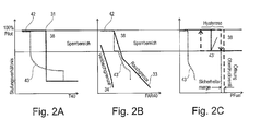
- the fields indicate areas that are undesirable for operation, ie operating points should not fall into these areas.
- a blocking region is the operating region which can not be adjusted during operation due to hydrodynamic and / or thermal boundary conditions.
- the keep-out zone 38 must be traversed very quickly, ie the grading ratio must be reduced practically instantaneously, which is indicated by the vertical operating line (see also Fig. 6 ).
- the desired steady state value is reached.
- Fig. 2B the behavior of an acceleration process under a transient control law 32 is represented in an analogous manner.
- the abscissa represents the fuel-air ratio FAR40.
- the operating line 43 runs here between the extinction limit of the flame 34 (protection against extinction of the flame) and the smoke limit 33.
- transient operating states 43 can lie between the region of the extinguishing limit 34 and the smoke limit 33.
- a weighted averaging can be carried out, so that in the case of acceleration, the transient operating states 43 are closer to the region of the extinction limit 34 and, in the case of the negative acceleration, closer to the region for the smoke limit 33.
- the staging ratio ⁇ will remain in pilot mode until the limit for fuel pressure is reached and then becomes set a staging ratio ⁇ , which keeps the pressure distribution within allowable limits. This smoke is accepted in order to avoid a loss of performance.
- FIG. 10 shows the behavior based on an operating line 43 under an acceleration, when protection against too high a fuel pressure 39 in the fuel system of the pilot burner A is desired. On the abscissa here the fuel pressure PFuel is plotted.
- Fig. 2C It is shown how a "fluttering" of the control of the fuel pressure 39 in the pilot fuel system can be prevented when the main burner B is switched off and on.
- a controller is used with a hysteresis, so that a lagging period is taken into account in the control.
- the main burner B In the case of acceleration, with increasing pressure in the pilot fuel system (abscissa), the main burner B is switched on instantaneously starting from a certain pressure limit, so that the grading ratio ⁇ decreases (alternative operating line 43 ', in particular for emergency operation).
- the value for the connection is below the pressure limit for the opening of the pressure valve, with which pressure is directed to the aircraft. This would lead to the loss of control over the engine thrust.
- the main burner B is switched off at a negative acceleration but not equal to falling below a certain pressure value again, as this could lead to a "flutter". Therefore, the main burner B is switched off again only at a lower pressure, which shows the hysteresis.
- Fig. 3 illustrates how an embodiment for setting the final graduation ratio ⁇ can ensure that the locked graduation ratios, such as in Fig. 2A to 2C and at the same time a prioritization of the automatic decisions is implemented so that the requirements for safety, operability and cost-effectiveness are met.
- a first adjusting device 1 which between the control laws for a stationary state 31 (see, eg Fig. 2A ) or the control laws for a transient state 32 (see eg Fig. 2B ) can switch.
- the stationary control laws 31 are designed for efficiency and low emissions and should be used as often as possible.
- the transient control laws 32 are designed for stability and are used when necessary.
- temperature values are used which are representative of the step ratio.
- this is eg the combustion chamber outlet temperature T40 (see Fig. 2A ).
- the fuel-air ratio (FAR40) see Fig. 2B
- an estimated turbine inlet temperature T40ant can be estimated by the position of the throttle lever, for example.
- the turbine outlet temperature T40ant can be predicted at the end of a transient maneuver on the basis of the thrust lever position, in order to be able to anticipate the change of the thermodynamic state when setting the step ratio.
- the output values of the control laws 31, 32 may be referred to as the steady state pilot split demand ratio and the transient pilot split demand ratio, respectively.
- the first adjusting device 1 selects between these gradation ratios.
- a determination means 41 for distinguishing the stationary from the transient operation for controlling the first setting means 1 (indicated by the dashed line in FIG Fig. 3 ).
- the determining means 41 is controlled in dependence on the estimated turbine inlet temperature T40ant.
- the preselected required grading ratio 11 thus obtained is then compared with a required grading ratio for the smoke limit 12, wherein the required grading ratio for the smoke threshold 12 is formed from a measurement and / or calculation of the smoke threshold 33.
- the respective smaller value of the preselected required grading ratio 11 and the required grading ratio for the smoke limit 12 is set as the first grading ratio parameter 21.
- This selection of the smallest (in other cases also a largest) value for the grading ratios 11, 12 is based on a normalization of the input quantities to a number range for the grading ratio, so that the grading ratios 11, 12 as input variables and the grading ratio parameter 21 as output variables are dimensionally comparable are. This applies to all Min / Max blocks, eg in the Fig. 3 are shown.
- a required grading ratio 13 for the quenching limit 34 is formed from a measurement and / or calculation that allows statements about the Weak Extinction Limit (WEX) 34.
- WEX Weak Extinction Limit
- This required grading ratio 13 for the quenching limit 34 is then compared with the preselected required grading ratio 11, the largest value being the second grading ratio parameter 22 is determined.
- the consideration of the extinction limit 34 and the smoke limit 33 already provides a relatively narrow space for the operating parameters. In this case, it is ensured that the quenching limit 34 has the higher priority than the smoke limit 33.
- the second adjustment device 2 may select a redundancy rule set 36 which provides a required grading ratio 14 for considering a redundancy rule set.
- the redundancy rule set 36 uses the steady state staging ratio and a simplified assumption of the transient staging ratio, and removes the more conservative (i.e., the larger one) therefrom.
- the redundancy rule set 36 is e.g. selected by the second adjusting device 2 when an error has been detected on the sensor inputs for the nominal control laws.
- the error handling also takes into account the "severity" of the error. If there are minor deviations, the faulty value will continue to be used or replaced by a model.
- the third gradation ratio parameter 23 is then formed.
- Turbine operating parameters 35 for characterizing abnormal operating conditions see FIG Fig. 5 ), wherein the evaluation provides a required grading ratio 15 for the consideration of turbine operating conditions.
- the third adjusting means 3 selects between the third grading ratio parameter 23 and the required grading ratio 15 for the consideration of turbine operating conditions and provides a fourth grading ratio parameter 24.
- the embodiment shown here is designed so that the aircraft engine can be operated as long as possible at low emissions, the Safety requirements always have the highest priority. It is also ensured that the conditions are provided with sufficient safety margins.
- the degree of filling with fuel (priming) 40 and the consideration of turbine operating parameters 35 for characterizing abnormal operating conditions are also included in the strategy.
- the fourth grading ratio parameter 24 is compared to a required minimum fuel flow staging ratio 16 derived from a determination of the total fuel flow 37.
- the control value derived from the total fuel flow 37 serves to prevent staging away from pure pilot operation when the total fuel flow 37 is very small.
- the problem in such a case is that in the main burner mode B, the mass flow is distributed to twice as many nozzles as in the pure pilot mode A. These nozzles are protected by spring-controlled control valves and are subject to manufacturing tolerances. At very low mass flow, only a part of the valves would open and one would have a highly inhomogeneous temperature distribution at the combustion chamber exit, because only a few burners would be active. The resulting temperature peaks could damage the turbine.
- the respective larger value forms the fifth gradation ratio parameter 25. This is compared with two further gradation ratios 17, 18, wherein the smallest of the three is set as the sixth gradation ratio parameter 26.
- a required grading ratio 17 for taking account of a blocking area is formed from a tax law, which deals with the controlled passing through the so-called keep-out zone 38 (blocking area). This will be in Fig. 6 explained in more detail.
- the required grading ratio 18 for protection against fuel overpressure is derived from a measurement and / or calculation of the fuel pressure 39 PFuel in the fuel system of the pilot burner A.
- the maximum fuel flow for the starting thrust can not be injected. Otherwise, the fuel system would be damaged by the overpressure.
- a grading should first be initiated. This case can only happen if the logic laws earlier in the logic, eg as a result of unrecognized sensor errors, have failed and command pure pilot operation, although the main injector could already have been switched on.
- a fourth adjusting device 4 selects between the sixth grading ratio parameter 26 and a required grading ratio 19 for the fuel filling degree of the injector.
- the required staging ratio 19 for the fuel filling level of the injector is derived from measurements and / or calculations concerning the filling of the fuel lines (priming).
- the priming function is based on a model which integrates the fuel flow into the main burner B. The integrator starts at zero. If a transition is commanded from pilot burner operation A to main burner operation B, the integrator will go high until the "filled" state is reached, assuming that the actual injector fills at approximately the same rate.
- a fixed staging ratio ⁇ is set. As soon as the filling is complete, the sixth graduation ratio parameter 26 is switched through as graduation ratio ⁇ .
- the formation of subcombinations of the values may be useful.
- robustness is implemented by allowing certain requirements to be abandoned, as long as the reliability of the aircraft engine is guaranteed and the flight can continue until repair is performed on the ground.
- the end result may be a conservative final staging ratio ⁇ which, under certain circumstances, leads to smoke formation but still ensures stable combustion (see, for example, Backup control law in Fig. 3 ).
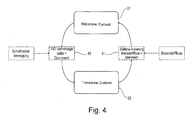
- Fig. 4 schematically shows how between stationary control laws 31 and transient control laws 32 is selected, the selection is carried out in dependence on the determining means 41.
- the determining means 41 determines whether the difference of the estimated Turbine inlet temperature T40ant at two different times exceeds a certain limit. If so, the transient control laws 32 are switched.
- a switch back to the stationary control laws 31 occurs when a measurement and / or calculation of the fuel flow shows that the change over time of the fuel flow has fallen below a certain limit.
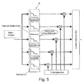
- Fig. 5 It is schematically illustrated which events may be used in turbine operating parameters 35 to characterize abnormal operating conditions to be used in a staging ratio adjustment apparatus or method. It is important that in abnormal operating conditions, the fuel-air ratio and / or the combustion chamber outlet temperature T40 may not be calculated correctly. Therefore, in this embodiment, the shaft speed is used as a robust parameter, which represents an approximate measure of the power conversion within the engine. As soon as the abnormal condition has ended (eg engine start complete, pump over, etc.), the system switches back to the optimal control laws. As a result, the event with the highest staging ratio is preferred in the case of several simultaneously active events
- the starting point is the detection of a shaft speed of the aircraft engine. This increases robustness since temperature measurements or determinations, e.g. the combustion chamber inlet temperature T40 or provisions of the fuel-air ratio FAR40 can be supplemented thereby.
- z.T. abnormal operating conditions are detected, e.g. starting the aircraft engine, re-igniting the aircraft engine, water intrusion, a surge in fuel delivery, or burner flame extinguishment.
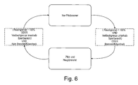
- Fig. 6 is shown for one embodiment, as the so-called keep-out zone 38 can be traversed in operation.
- This is a zone in which due to hydrodynamic and / or thermal conditions no permanent operation is possible.
- traversing the keep-out zone 38 is to ensure that a for cooling the Hauptbrennerzutechnischen required minimum fuel flow is not exceeded.
- the smoke and extinguishing limits thus determine the switching on and off of the main burner B.
Landscapes
- Engineering & Computer Science (AREA)
- Chemical & Material Sciences (AREA)
- Combustion & Propulsion (AREA)
- Mechanical Engineering (AREA)
- General Engineering & Computer Science (AREA)
- Control Of Turbines (AREA)
- Feedback Control In General (AREA)
Applications Claiming Priority (1)
| Application Number | Priority Date | Filing Date | Title |
|---|---|---|---|
| DE102014223637.1A DE102014223637A1 (de) | 2014-11-19 | 2014-11-19 | Vorrichtung zur Bestimmung eines Stufungsverhältnisses, eine Gasturbine oder ein Flugzeugtriebwerk mit einer solchen Vorrichtung und eine Verwendung dafür |
Publications (2)
| Publication Number | Publication Date |
|---|---|
| EP3023698A1 true EP3023698A1 (fr) | 2016-05-25 |
| EP3023698B1 EP3023698B1 (fr) | 2018-04-04 |
Family
ID=54608340
Family Applications (1)
| Application Number | Title | Priority Date | Filing Date |
|---|---|---|---|
| EP15195002.9A Active EP3023698B1 (fr) | 2014-11-19 | 2015-11-17 | Dispositif de détermination d'un rapport d'étagement, une turbine a gaz ou moteur d'aeronef comprenant un tel dispositif et son utilisation |
Country Status (3)
| Country | Link |
|---|---|
| US (1) | US10156361B2 (fr) |
| EP (1) | EP3023698B1 (fr) |
| DE (1) | DE102014223637A1 (fr) |
Cited By (3)
| Publication number | Priority date | Publication date | Assignee | Title |
|---|---|---|---|---|
| EP3457030A1 (fr) * | 2017-09-18 | 2019-03-20 | Siemens Aktiengesellschaft | Organe de commande et procédé |
| US11156164B2 (en) | 2019-05-21 | 2021-10-26 | General Electric Company | System and method for high frequency accoustic dampers with caps |
| US11174792B2 (en) | 2019-05-21 | 2021-11-16 | General Electric Company | System and method for high frequency acoustic dampers with baffles |
Families Citing this family (11)
| Publication number | Priority date | Publication date | Assignee | Title |
|---|---|---|---|---|
| US10006330B2 (en) * | 2014-10-28 | 2018-06-26 | General Electric Company | System and method for emissions control in gas turbine systems |
| US11181274B2 (en) | 2017-08-21 | 2021-11-23 | General Electric Company | Combustion system and method for attenuation of combustion dynamics in a gas turbine engine |
| US10816211B2 (en) | 2017-08-25 | 2020-10-27 | Honeywell International Inc. | Axially staged rich quench lean combustion system |
| US11378277B2 (en) | 2018-04-06 | 2022-07-05 | General Electric Company | Gas turbine engine and combustor having air inlets and pilot burner |
| US11203986B1 (en) * | 2020-06-08 | 2021-12-21 | General Electric Company | Systems and methods for extended emissions compliant operation of a gas turbine engine |
| US11333082B2 (en) * | 2020-06-12 | 2022-05-17 | General Electric Company | Systems and methods for determination of gas turbine fuel split for head end temperature control |
| CN114909224B (zh) * | 2021-02-09 | 2024-06-07 | 中国航发商用航空发动机有限责任公司 | 一种燃烧不稳定性控制方法和系统 |
| GB202205355D0 (en) | 2022-04-12 | 2022-05-25 | Rolls Royce Plc | Gas turbine operation |
| GB202205358D0 (en) | 2022-04-12 | 2022-05-25 | Rolls Royce Plc | Loading parameters |
| GB202205354D0 (en) | 2022-04-12 | 2022-05-25 | Rolls Royce Plc | Fuel delivery |
| GB202205353D0 (en) * | 2022-04-12 | 2022-05-25 | Rolls Royce Plc | Flight condition |
Citations (8)
| Publication number | Priority date | Publication date | Assignee | Title |
|---|---|---|---|---|
| WO1993009339A1 (fr) * | 1991-10-29 | 1993-05-13 | Rolls-Royce Plc | Systeme de commande d'un moteur a turbine |
| US5261222A (en) * | 1991-08-12 | 1993-11-16 | General Electric Company | Fuel delivery method for dual annular combuster |
| WO1995017632A1 (fr) | 1993-12-22 | 1995-06-29 | United Technologies Corporation | Systeme de regulation du carburant d'un bruleur etage |
| EP0733861A2 (fr) * | 1995-03-24 | 1996-09-25 | ABB Management AG | Chambre de combustion à combustion étagée |
| US6389816B1 (en) * | 2000-07-25 | 2002-05-21 | Honeywell International, Inc. | Simplified fuel system for jet engines |
| EP1079179B1 (fr) | 1999-08-21 | 2004-11-24 | Rolls-Royce Deutschland Ltd & Co KG | Procédé pour l'adaptation de l'état de fonctionnement d'une chambre de combustion étagée de turbines à gaz |
| EP1746347A2 (fr) * | 2005-07-21 | 2007-01-24 | Rolls-Royce plc | Procédé et système pour une chambre à combustion étagée |
| US20120017600A1 (en) * | 2010-07-23 | 2012-01-26 | Hitachi, Ltd. | Combustor Control Method and Combustor Controller |
Family Cites Families (7)
| Publication number | Priority date | Publication date | Assignee | Title |
|---|---|---|---|---|
| US4716723A (en) * | 1986-09-05 | 1988-01-05 | Woodward Governor Company | Fuel controls for gas turbine engines |
| US5319931A (en) * | 1992-12-30 | 1994-06-14 | General Electric Company | Fuel trim method for a multiple chamber gas turbine combustion system |
| US6095793A (en) * | 1998-09-18 | 2000-08-01 | Woodward Governor Company | Dynamic control system and method for catalytic combustion process and gas turbine engine utilizing same |
| US7032388B2 (en) * | 2003-11-17 | 2006-04-25 | General Electric Company | Method and system for incorporating an emission sensor into a gas turbine controller |
| US9097185B2 (en) * | 2009-05-26 | 2015-08-04 | Alstom Technology Ltd | Stabilizing a gas turbine engine via incremental tuning |
| US8417433B2 (en) * | 2010-04-30 | 2013-04-09 | Alstom Technology Ltd. | Dynamically auto-tuning a gas turbine engine |
| US20140150438A1 (en) * | 2012-11-30 | 2014-06-05 | General Electric Company | System and method for operating a gas turbine in a turndown mode |
-
2014
- 2014-11-19 DE DE102014223637.1A patent/DE102014223637A1/de not_active Withdrawn
-
2015
- 2015-11-17 US US14/943,879 patent/US10156361B2/en active Active
- 2015-11-17 EP EP15195002.9A patent/EP3023698B1/fr active Active
Patent Citations (8)
| Publication number | Priority date | Publication date | Assignee | Title |
|---|---|---|---|---|
| US5261222A (en) * | 1991-08-12 | 1993-11-16 | General Electric Company | Fuel delivery method for dual annular combuster |
| WO1993009339A1 (fr) * | 1991-10-29 | 1993-05-13 | Rolls-Royce Plc | Systeme de commande d'un moteur a turbine |
| WO1995017632A1 (fr) | 1993-12-22 | 1995-06-29 | United Technologies Corporation | Systeme de regulation du carburant d'un bruleur etage |
| EP0733861A2 (fr) * | 1995-03-24 | 1996-09-25 | ABB Management AG | Chambre de combustion à combustion étagée |
| EP1079179B1 (fr) | 1999-08-21 | 2004-11-24 | Rolls-Royce Deutschland Ltd & Co KG | Procédé pour l'adaptation de l'état de fonctionnement d'une chambre de combustion étagée de turbines à gaz |
| US6389816B1 (en) * | 2000-07-25 | 2002-05-21 | Honeywell International, Inc. | Simplified fuel system for jet engines |
| EP1746347A2 (fr) * | 2005-07-21 | 2007-01-24 | Rolls-Royce plc | Procédé et système pour une chambre à combustion étagée |
| US20120017600A1 (en) * | 2010-07-23 | 2012-01-26 | Hitachi, Ltd. | Combustor Control Method and Combustor Controller |
Cited By (5)
| Publication number | Priority date | Publication date | Assignee | Title |
|---|---|---|---|---|
| EP3457030A1 (fr) * | 2017-09-18 | 2019-03-20 | Siemens Aktiengesellschaft | Organe de commande et procédé |
| WO2019053043A1 (fr) * | 2017-09-18 | 2019-03-21 | Siemens Aktiengesellschaft | Unité de commande et procédé |
| US11261802B2 (en) | 2017-09-18 | 2022-03-01 | Siemens Energy Global GmbH & Co. KG | Controller and method |
| US11156164B2 (en) | 2019-05-21 | 2021-10-26 | General Electric Company | System and method for high frequency accoustic dampers with caps |
| US11174792B2 (en) | 2019-05-21 | 2021-11-16 | General Electric Company | System and method for high frequency acoustic dampers with baffles |
Also Published As
| Publication number | Publication date |
|---|---|
| US10156361B2 (en) | 2018-12-18 |
| EP3023698B1 (fr) | 2018-04-04 |
| DE102014223637A1 (de) | 2016-06-09 |
| US20160138808A1 (en) | 2016-05-19 |
Similar Documents
| Publication | Publication Date | Title |
|---|---|---|
| EP3023698B1 (fr) | Dispositif de détermination d'un rapport d'étagement, une turbine a gaz ou moteur d'aeronef comprenant un tel dispositif et son utilisation | |
| DE69225912T2 (de) | Steuervorrichtung für ein gasturbinentriebwerk | |
| DE69010080T2 (de) | Brennstoffregelsystem eines Gasturbinenmotors mit verbesserter Wiederzündfähigkeit. | |
| EP1621811B1 (fr) | Procédé de fonctionnement pour un dispositif de combustion | |
| DE69614059T2 (de) | Kraftstoffregelsystem für eine Gasturbine | |
| DE10142514B4 (de) | Verfahren zum Feststellen eines Flammenrückschlags in einem Gasturbinensystem, sowie Gasturbinensystem | |
| EP1079179B1 (fr) | Procédé pour l'adaptation de l'état de fonctionnement d'une chambre de combustion étagée de turbines à gaz | |
| DE102011052422A1 (de) | Verfahren, Vorrichtung und System für die Zufuhr von zur Verbrennung bestimmten Turbinenkraftstoffen unterschiedlicher Qualität | |
| EP1472447A1 (fr) | Procede d'utilisation d'un groupe de turbines a gaz | |
| DE112018005654T5 (de) | Steuervorrichtung, gasturbine, steuerverfahren und programm | |
| CH697743B1 (de) | Gasturbinenmotor mit Inline-Gasbrennstoff-Reformierer sowie Verfahren zum Regeln der Wobbezahl eines Gasbrennstoffes. | |
| CH708571A2 (de) | Gasturbinensystem und Verfahren zur Steuerung der Brennstoffverteilung in den Brennkammern einer Gasturbine. | |
| DE1601560A1 (de) | Steuersystem fuer Axialstroemungskompressoren,insbesondere fuer Gasturbinentriebwerke | |
| DE112016003474T5 (de) | Brennstoff-fliessgeschwindigkeit-einstellverfahren, vorrichtung zum implementieren des verfahrens und mit der vorrichtung versehene gasturbinenanlage | |
| EP1840465A2 (fr) | Système comportant des brûleurs à injection de carburant étagée | |
| DE102012015454A1 (de) | Verfahren zur Regelung der Kraftstofftemperatur einer Gasturbine | |
| CH698404A2 (de) | Lean-Blowout-Auslöschschutz durch Regelung der Düsen-Äquivalenzverhältnisse. | |
| CH697864A2 (de) | Verfahren zur Bestimmung der Zusammensetzung des in eine Brennkammer eintretenden Kraftstoffs. | |
| DE112020002338T5 (de) | Vorrichtung zur verbrennungssteuerung für gasturbine, verfahren zur verbrennungssteuerung und programm | |
| DE112014000907B4 (de) | Gasturbinensystem, Gasturbinenbrennkammer-Steuervorrichtung und Gasturbinenbrennkammer-Steuerverfahren | |
| EP1533569B1 (fr) | Méthode de fonctionnement d'un appareil de combustion | |
| CH708626A2 (de) | Verfahren und System zum Betreiben eines Gasturbinen-Verbrennungs-Systems. | |
| DE4002803C2 (fr) | ||
| DE69205049T2 (de) | Flammenversageerkennung. | |
| CH708856A2 (de) | Verfahren zum Steuern/Regeln des Betriebs einer Gasturbine während des Teillastbetriebs. |
Legal Events
| Date | Code | Title | Description |
|---|---|---|---|
| AK | Designated contracting states |
Kind code of ref document: A1 Designated state(s): AL AT BE BG CH CY CZ DE DK EE ES FI FR GB GR HR HU IE IS IT LI LT LU LV MC MK MT NL NO PL PT RO RS SE SI SK SM TR |
|
| AX | Request for extension of the european patent |
Extension state: BA ME |
|
| PUAI | Public reference made under article 153(3) epc to a published international application that has entered the european phase |
Free format text: ORIGINAL CODE: 0009012 |
|
| 17P | Request for examination filed |
Effective date: 20161005 |
|
| RBV | Designated contracting states (corrected) |
Designated state(s): AL AT BE BG CH CY CZ DE DK EE ES FI FR GB GR HR HU IE IS IT LI LT LU LV MC MK MT NL NO PL PT RO RS SE SI SK SM TR |
|
| REG | Reference to a national code |
Ref country code: DE Ref legal event code: R079 Ref document number: 502015003712 Country of ref document: DE Free format text: PREVIOUS MAIN CLASS: F23R0003340000 Ipc: F02C0007228000 |
|
| GRAP | Despatch of communication of intention to grant a patent |
Free format text: ORIGINAL CODE: EPIDOSNIGR1 |
|
| RIC1 | Information provided on ipc code assigned before grant |
Ipc: F02C 9/28 20060101ALI20171103BHEP Ipc: F23R 3/34 20060101ALI20171103BHEP Ipc: F02C 9/34 20060101ALI20171103BHEP Ipc: F02C 7/228 20060101AFI20171103BHEP |
|
| INTG | Intention to grant announced |
Effective date: 20171124 |
|
| RIN1 | Information on inventor provided before grant (corrected) |
Inventor name: HUEBNER, GERHARD Inventor name: LEWARK, ANDREAS Inventor name: LEITGES, FABIAN |
|
| GRAS | Grant fee paid |
Free format text: ORIGINAL CODE: EPIDOSNIGR3 |
|
| GRAA | (expected) grant |
Free format text: ORIGINAL CODE: 0009210 |
|
| AK | Designated contracting states |
Kind code of ref document: B1 Designated state(s): AL AT BE BG CH CY CZ DE DK EE ES FI FR GB GR HR HU IE IS IT LI LT LU LV MC MK MT NL NO PL PT RO RS SE SI SK SM TR |
|
| REG | Reference to a national code |
Ref country code: GB Ref legal event code: FG4D Free format text: NOT ENGLISH |
|
| REG | Reference to a national code |
Ref country code: CH Ref legal event code: EP |
|
| REG | Reference to a national code |
Ref country code: AT Ref legal event code: REF Ref document number: 985856 Country of ref document: AT Kind code of ref document: T Effective date: 20180415 |
|
| REG | Reference to a national code |
Ref country code: IE Ref legal event code: FG4D Free format text: LANGUAGE OF EP DOCUMENT: GERMAN |
|
| REG | Reference to a national code |
Ref country code: DE Ref legal event code: R096 Ref document number: 502015003712 Country of ref document: DE |
|
| REG | Reference to a national code |
Ref country code: NL Ref legal event code: MP Effective date: 20180404 |
|
| REG | Reference to a national code |
Ref country code: LT Ref legal event code: MG4D |
|
| PG25 | Lapsed in a contracting state [announced via postgrant information from national office to epo] |
Ref country code: NL Free format text: LAPSE BECAUSE OF FAILURE TO SUBMIT A TRANSLATION OF THE DESCRIPTION OR TO PAY THE FEE WITHIN THE PRESCRIBED TIME-LIMIT Effective date: 20180404 |
|
| PG25 | Lapsed in a contracting state [announced via postgrant information from national office to epo] |
Ref country code: SE Free format text: LAPSE BECAUSE OF FAILURE TO SUBMIT A TRANSLATION OF THE DESCRIPTION OR TO PAY THE FEE WITHIN THE PRESCRIBED TIME-LIMIT Effective date: 20180404 Ref country code: AL Free format text: LAPSE BECAUSE OF FAILURE TO SUBMIT A TRANSLATION OF THE DESCRIPTION OR TO PAY THE FEE WITHIN THE PRESCRIBED TIME-LIMIT Effective date: 20180404 Ref country code: FI Free format text: LAPSE BECAUSE OF FAILURE TO SUBMIT A TRANSLATION OF THE DESCRIPTION OR TO PAY THE FEE WITHIN THE PRESCRIBED TIME-LIMIT Effective date: 20180404 Ref country code: BG Free format text: LAPSE BECAUSE OF FAILURE TO SUBMIT A TRANSLATION OF THE DESCRIPTION OR TO PAY THE FEE WITHIN THE PRESCRIBED TIME-LIMIT Effective date: 20180704 Ref country code: NO Free format text: LAPSE BECAUSE OF FAILURE TO SUBMIT A TRANSLATION OF THE DESCRIPTION OR TO PAY THE FEE WITHIN THE PRESCRIBED TIME-LIMIT Effective date: 20180704 Ref country code: PL Free format text: LAPSE BECAUSE OF FAILURE TO SUBMIT A TRANSLATION OF THE DESCRIPTION OR TO PAY THE FEE WITHIN THE PRESCRIBED TIME-LIMIT Effective date: 20180404 Ref country code: LT Free format text: LAPSE BECAUSE OF FAILURE TO SUBMIT A TRANSLATION OF THE DESCRIPTION OR TO PAY THE FEE WITHIN THE PRESCRIBED TIME-LIMIT Effective date: 20180404 Ref country code: ES Free format text: LAPSE BECAUSE OF FAILURE TO SUBMIT A TRANSLATION OF THE DESCRIPTION OR TO PAY THE FEE WITHIN THE PRESCRIBED TIME-LIMIT Effective date: 20180404 |
|
| PG25 | Lapsed in a contracting state [announced via postgrant information from national office to epo] |
Ref country code: GR Free format text: LAPSE BECAUSE OF FAILURE TO SUBMIT A TRANSLATION OF THE DESCRIPTION OR TO PAY THE FEE WITHIN THE PRESCRIBED TIME-LIMIT Effective date: 20180705 Ref country code: HR Free format text: LAPSE BECAUSE OF FAILURE TO SUBMIT A TRANSLATION OF THE DESCRIPTION OR TO PAY THE FEE WITHIN THE PRESCRIBED TIME-LIMIT Effective date: 20180404 Ref country code: RS Free format text: LAPSE BECAUSE OF FAILURE TO SUBMIT A TRANSLATION OF THE DESCRIPTION OR TO PAY THE FEE WITHIN THE PRESCRIBED TIME-LIMIT Effective date: 20180404 Ref country code: LV Free format text: LAPSE BECAUSE OF FAILURE TO SUBMIT A TRANSLATION OF THE DESCRIPTION OR TO PAY THE FEE WITHIN THE PRESCRIBED TIME-LIMIT Effective date: 20180404 |
|
| PG25 | Lapsed in a contracting state [announced via postgrant information from national office to epo] |
Ref country code: PT Free format text: LAPSE BECAUSE OF FAILURE TO SUBMIT A TRANSLATION OF THE DESCRIPTION OR TO PAY THE FEE WITHIN THE PRESCRIBED TIME-LIMIT Effective date: 20180806 |
|
| REG | Reference to a national code |
Ref country code: DE Ref legal event code: R097 Ref document number: 502015003712 Country of ref document: DE |
|
| PG25 | Lapsed in a contracting state [announced via postgrant information from national office to epo] |
Ref country code: CZ Free format text: LAPSE BECAUSE OF FAILURE TO SUBMIT A TRANSLATION OF THE DESCRIPTION OR TO PAY THE FEE WITHIN THE PRESCRIBED TIME-LIMIT Effective date: 20180404 Ref country code: RO Free format text: LAPSE BECAUSE OF FAILURE TO SUBMIT A TRANSLATION OF THE DESCRIPTION OR TO PAY THE FEE WITHIN THE PRESCRIBED TIME-LIMIT Effective date: 20180404 Ref country code: EE Free format text: LAPSE BECAUSE OF FAILURE TO SUBMIT A TRANSLATION OF THE DESCRIPTION OR TO PAY THE FEE WITHIN THE PRESCRIBED TIME-LIMIT Effective date: 20180404 Ref country code: DK Free format text: LAPSE BECAUSE OF FAILURE TO SUBMIT A TRANSLATION OF THE DESCRIPTION OR TO PAY THE FEE WITHIN THE PRESCRIBED TIME-LIMIT Effective date: 20180404 Ref country code: SK Free format text: LAPSE BECAUSE OF FAILURE TO SUBMIT A TRANSLATION OF THE DESCRIPTION OR TO PAY THE FEE WITHIN THE PRESCRIBED TIME-LIMIT Effective date: 20180404 |
|
| PLBE | No opposition filed within time limit |
Free format text: ORIGINAL CODE: 0009261 |
|
| STAA | Information on the status of an ep patent application or granted ep patent |
Free format text: STATUS: NO OPPOSITION FILED WITHIN TIME LIMIT |
|
| PG25 | Lapsed in a contracting state [announced via postgrant information from national office to epo] |
Ref country code: IT Free format text: LAPSE BECAUSE OF FAILURE TO SUBMIT A TRANSLATION OF THE DESCRIPTION OR TO PAY THE FEE WITHIN THE PRESCRIBED TIME-LIMIT Effective date: 20180404 Ref country code: SM Free format text: LAPSE BECAUSE OF FAILURE TO SUBMIT A TRANSLATION OF THE DESCRIPTION OR TO PAY THE FEE WITHIN THE PRESCRIBED TIME-LIMIT Effective date: 20180404 |
|
| 26N | No opposition filed |
Effective date: 20190107 |
|
| PG25 | Lapsed in a contracting state [announced via postgrant information from national office to epo] |
Ref country code: SI Free format text: LAPSE BECAUSE OF FAILURE TO SUBMIT A TRANSLATION OF THE DESCRIPTION OR TO PAY THE FEE WITHIN THE PRESCRIBED TIME-LIMIT Effective date: 20180404 |
|
| REG | Reference to a national code |
Ref country code: CH Ref legal event code: PL |
|
| PG25 | Lapsed in a contracting state [announced via postgrant information from national office to epo] |
Ref country code: LU Free format text: LAPSE BECAUSE OF NON-PAYMENT OF DUE FEES Effective date: 20181117 Ref country code: MC Free format text: LAPSE BECAUSE OF FAILURE TO SUBMIT A TRANSLATION OF THE DESCRIPTION OR TO PAY THE FEE WITHIN THE PRESCRIBED TIME-LIMIT Effective date: 20180404 |
|
| REG | Reference to a national code |
Ref country code: BE Ref legal event code: MM Effective date: 20181130 |
|
| REG | Reference to a national code |
Ref country code: IE Ref legal event code: MM4A |
|
| PG25 | Lapsed in a contracting state [announced via postgrant information from national office to epo] |
Ref country code: LI Free format text: LAPSE BECAUSE OF NON-PAYMENT OF DUE FEES Effective date: 20181130 Ref country code: CH Free format text: LAPSE BECAUSE OF NON-PAYMENT OF DUE FEES Effective date: 20181130 |
|
| PG25 | Lapsed in a contracting state [announced via postgrant information from national office to epo] |
Ref country code: IE Free format text: LAPSE BECAUSE OF NON-PAYMENT OF DUE FEES Effective date: 20181117 |
|
| PG25 | Lapsed in a contracting state [announced via postgrant information from national office to epo] |
Ref country code: BE Free format text: LAPSE BECAUSE OF NON-PAYMENT OF DUE FEES Effective date: 20181130 |
|
| PG25 | Lapsed in a contracting state [announced via postgrant information from national office to epo] |
Ref country code: MT Free format text: LAPSE BECAUSE OF FAILURE TO SUBMIT A TRANSLATION OF THE DESCRIPTION OR TO PAY THE FEE WITHIN THE PRESCRIBED TIME-LIMIT Effective date: 20180404 |
|
| PG25 | Lapsed in a contracting state [announced via postgrant information from national office to epo] |
Ref country code: TR Free format text: LAPSE BECAUSE OF FAILURE TO SUBMIT A TRANSLATION OF THE DESCRIPTION OR TO PAY THE FEE WITHIN THE PRESCRIBED TIME-LIMIT Effective date: 20180404 |
|
| PGFP | Annual fee paid to national office [announced via postgrant information from national office to epo] |
Ref country code: GB Payment date: 20191127 Year of fee payment: 5 |
|
| PG25 | Lapsed in a contracting state [announced via postgrant information from national office to epo] |
Ref country code: CY Free format text: LAPSE BECAUSE OF FAILURE TO SUBMIT A TRANSLATION OF THE DESCRIPTION OR TO PAY THE FEE WITHIN THE PRESCRIBED TIME-LIMIT Effective date: 20180404 Ref country code: MK Free format text: LAPSE BECAUSE OF NON-PAYMENT OF DUE FEES Effective date: 20180404 Ref country code: HU Free format text: LAPSE BECAUSE OF FAILURE TO SUBMIT A TRANSLATION OF THE DESCRIPTION OR TO PAY THE FEE WITHIN THE PRESCRIBED TIME-LIMIT; INVALID AB INITIO Effective date: 20151117 |
|
| PG25 | Lapsed in a contracting state [announced via postgrant information from national office to epo] |
Ref country code: IS Free format text: LAPSE BECAUSE OF FAILURE TO SUBMIT A TRANSLATION OF THE DESCRIPTION OR TO PAY THE FEE WITHIN THE PRESCRIBED TIME-LIMIT Effective date: 20180804 |
|
| GBPC | Gb: european patent ceased through non-payment of renewal fee |
Effective date: 20201117 |
|
| PG25 | Lapsed in a contracting state [announced via postgrant information from national office to epo] |
Ref country code: GB Free format text: LAPSE BECAUSE OF NON-PAYMENT OF DUE FEES Effective date: 20201117 |
|
| REG | Reference to a national code |
Ref country code: AT Ref legal event code: MM01 Ref document number: 985856 Country of ref document: AT Kind code of ref document: T Effective date: 20201117 |
|
| PG25 | Lapsed in a contracting state [announced via postgrant information from national office to epo] |
Ref country code: AT Free format text: LAPSE BECAUSE OF NON-PAYMENT OF DUE FEES Effective date: 20201117 |
|
| P01 | Opt-out of the competence of the unified patent court (upc) registered |
Effective date: 20230528 |
|
| PGFP | Annual fee paid to national office [announced via postgrant information from national office to epo] |
Ref country code: DE Payment date: 20251126 Year of fee payment: 11 |
|
| PGFP | Annual fee paid to national office [announced via postgrant information from national office to epo] |
Ref country code: FR Payment date: 20251124 Year of fee payment: 11 |