EP3023751A2 - Fuel density determination - Google Patents
Fuel density determination Download PDFInfo
- Publication number
- EP3023751A2 EP3023751A2 EP15192089.9A EP15192089A EP3023751A2 EP 3023751 A2 EP3023751 A2 EP 3023751A2 EP 15192089 A EP15192089 A EP 15192089A EP 3023751 A2 EP3023751 A2 EP 3023751A2
- Authority
- EP
- European Patent Office
- Prior art keywords
- fuel
- location
- dielectric constant
- density
- plate
- Prior art date
- Legal status (The legal status is an assumption and is not a legal conclusion. Google has not performed a legal analysis and makes no representation as to the accuracy of the status listed.)
- Granted
Links
Images


Classifications
-
- G—PHYSICS
- G01—MEASURING; TESTING
- G01N—INVESTIGATING OR ANALYSING MATERIALS BY DETERMINING THEIR CHEMICAL OR PHYSICAL PROPERTIES
- G01N9/00—Investigating density or specific gravity of materials; Analysing materials by determining density or specific gravity
-
- G—PHYSICS
- G01—MEASURING; TESTING
- G01F—MEASURING VOLUME, VOLUME FLOW, MASS FLOW OR LIQUID LEVEL; METERING BY VOLUME
- G01F1/00—Measuring the volume flow or mass flow of fluid or fluent solid material wherein the fluid passes through a meter in a continuous flow
-
- G—PHYSICS
- G01—MEASURING; TESTING
- G01F—MEASURING VOLUME, VOLUME FLOW, MASS FLOW OR LIQUID LEVEL; METERING BY VOLUME
- G01F1/00—Measuring the volume flow or mass flow of fluid or fluent solid material wherein the fluid passes through a meter in a continuous flow
- G01F1/76—Devices for measuring mass flow of a fluid or a fluent solid material
- G01F1/86—Indirect mass flowmeters, e.g. measuring volume flow and density, temperature or pressure
-
- G—PHYSICS
- G01—MEASURING; TESTING
- G01F—MEASURING VOLUME, VOLUME FLOW, MASS FLOW OR LIQUID LEVEL; METERING BY VOLUME
- G01F25/00—Testing or calibration of apparatus for measuring volume, volume flow or liquid level or for metering by volume
- G01F25/10—Testing or calibration of apparatus for measuring volume, volume flow or liquid level or for metering by volume of flowmeters
-
- G—PHYSICS
- G01—MEASURING; TESTING
- G01M—TESTING STATIC OR DYNAMIC BALANCE OF MACHINES OR STRUCTURES; TESTING OF STRUCTURES OR APPARATUS, NOT OTHERWISE PROVIDED FOR
- G01M15/00—Testing of engines
- G01M15/14—Testing gas-turbine engines or jet-propulsion engines
-
- G—PHYSICS
- G01—MEASURING; TESTING
- G01N—INVESTIGATING OR ANALYSING MATERIALS BY DETERMINING THEIR CHEMICAL OR PHYSICAL PROPERTIES
- G01N27/00—Investigating or analysing materials by the use of electric, electrochemical, or magnetic means
- G01N27/02—Investigating or analysing materials by the use of electric, electrochemical, or magnetic means by investigating impedance
- G01N27/22—Investigating or analysing materials by the use of electric, electrochemical, or magnetic means by investigating impedance by investigating capacitance
- G01N27/221—Investigating or analysing materials by the use of electric, electrochemical, or magnetic means by investigating impedance by investigating capacitance by investigating the dielectric properties
-
- G—PHYSICS
- G01—MEASURING; TESTING
- G01N—INVESTIGATING OR ANALYSING MATERIALS BY DETERMINING THEIR CHEMICAL OR PHYSICAL PROPERTIES
- G01N33/00—Investigating or analysing materials by specific methods not covered by groups G01N1/00 - G01N31/00
- G01N33/22—Fuels; Explosives
-
- G—PHYSICS
- G01—MEASURING; TESTING
- G01N—INVESTIGATING OR ANALYSING MATERIALS BY DETERMINING THEIR CHEMICAL OR PHYSICAL PROPERTIES
- G01N33/00—Investigating or analysing materials by specific methods not covered by groups G01N1/00 - G01N31/00
- G01N33/22—Fuels; Explosives
- G01N33/225—Gaseous fuels, e.g. natural gas
-
- G—PHYSICS
- G01—MEASURING; TESTING
- G01N—INVESTIGATING OR ANALYSING MATERIALS BY DETERMINING THEIR CHEMICAL OR PHYSICAL PROPERTIES
- G01N27/00—Investigating or analysing materials by the use of electric, electrochemical, or magnetic means
- G01N27/02—Investigating or analysing materials by the use of electric, electrochemical, or magnetic means by investigating impedance
- G01N27/22—Investigating or analysing materials by the use of electric, electrochemical, or magnetic means by investigating impedance by investigating capacitance
- G01N27/221—Investigating or analysing materials by the use of electric, electrochemical, or magnetic means by investigating impedance by investigating capacitance by investigating the dielectric properties
- G01N2027/222—Investigating or analysing materials by the use of electric, electrochemical, or magnetic means by investigating impedance by investigating capacitance by investigating the dielectric properties for analysing gases
-
- G—PHYSICS
- G01—MEASURING; TESTING
- G01N—INVESTIGATING OR ANALYSING MATERIALS BY DETERMINING THEIR CHEMICAL OR PHYSICAL PROPERTIES
- G01N27/00—Investigating or analysing materials by the use of electric, electrochemical, or magnetic means
- G01N27/02—Investigating or analysing materials by the use of electric, electrochemical, or magnetic means by investigating impedance
- G01N27/22—Investigating or analysing materials by the use of electric, electrochemical, or magnetic means by investigating impedance by investigating capacitance
- G01N27/226—Construction of measuring vessels; Electrodes therefor
Definitions
- the present embodiments relate generally to fluid-gauging assemblies and methods, and more particularly to fluid-gauging assemblies and methods for determining properties of fuel used in a gas turbine engine.
- a gas turbine engine can be used on an aircraft.
- aircraft engine control it can be necessary to know a value of a mass flow of fuel due to mass flow's direct effect on engine thrust.
- Prior fuel gauging techniques have obtained fuel mass flow values using moving components within the engine. For example, two impellers connected by a shaft with a known spring constant have been used to find fuel mass flow given the proportional relation between torque on the shaft (and thus impeller angular displacement) and fuel mass flow.
- fuel-gauging techniques which utilize moving components are undesirable.
- Fuel mass flow is equal to the product of fuel volumetric flow and fuel density. Fuel volumetric flow is readily obtained using known techniques. Thus, an accurate measurement of fuel density can yield fuel mass flow.
- Prior fuel gauging techniques have attempted to accurately determine fuel density by either directly measuring fuel density in a fuel tank external to the engine using some form of a densitometer, or measuring a dielectric constant of the fuel in the fuel tank external to the engine and then deducing fuel density using this measured dielectric constant in the fuel tank.
- prior fuel gauging techniques have attempted to accurately determine fuel density by either directly measuring fuel density in a fuel tank external to the engine using some form of a densitometer, or measuring a dielectric constant of the fuel in the fuel tank external to the engine and then deducing fuel density using this measured dielectric constant in the fuel tank.
- such techniques do not provide an accurate enough measurement of fuel density to allow for precise, economical aircraft engine control.
- One embodiment includes a method for accurately determining a density of a fuel.
- the method includes obtaining dielectric constant versus density characteristics of the fuel at a first location and measuring a dielectric constant of the fuel at a second location.
- the environmental conditions at the second location differ from environmental conditions at the first location. Density of the fuel at the second location is inferred using the dielectric constant of the fuel at the second location and the dielectric constant versus density characteristics of the fuel at the first location.
- the assembly includes a fuel line through which a fuel is passed and located at least partially within an engine, a fuel metering valve located within the fuel line and configured to receive the fuel through a first end and dispel the fuel through a second end, and a multi-plate capacitor device located within the fuel line through which the fuel passes.
- the device includes a first current sensing electrode plate, a second voltage driven electrode plate configured concentrically around the first plate, and an insulating material configured concentrically between the first plate and the second plate.
- the insulating material is present in an angular range between the first plate and the second plate less than 360° such that at least one gap is defined radially between the first plate and the second plate and along an axial distance of the first plate and the second plate.
- the at least one gap receives fuel at an upstream end and dispels fuel at a downstream end such that a first measurement of capacitance of the fuel can be obtained across the at least one gap.
- FIG 1A is a schematic diagram of an aircraft 9 which includes an assembly 10 for accurately determining a density of fuel 12.
- Assembly 10 includes fuel 12 which is stored in fuel tank 14.
- fuel 12 can be, for example, a kerosene-based or kerosene-like fuel such as Jet A, Jet A1, Jet B, JP 4, JP 5, or JP 8, with or without additives such as stabilizers, etc.
- Fuel tank 14 is supplied with fuel 12 and serves to store fuel 12.
- density sensor 16 and dielectric sensor 18 are mounted on a bottom of fuel tank 14 such that these sensors 16 and 18 are generally fully immersed in fuel 12 regardless of whether a volume of fuel tank 14 is near full or near empty of fuel 12.
- sensors 16 and 18 can be mounted at least partially within fuel tank 14 at various other locations within fuel tank 14.
- Density sensor 16 can be, for example, a form of densitometer or any other device suitable for accurately measuring a density of fuel 12 within fuel tank 14.
- Dielectric sensor 18 can be, for example, a capacitor or any other device suitable for accurately measuring a dielectric constant (i.e. relative permittivity) of fuel 12 (i.e. where fuel 12 is the dielectric and the dielectric constant is relative to air).
- Assembly 10 also includes fuel line 20, which is in fluid communication with both fuel tank 14 on one end and engine 22, on another end.
- Fuel line 20 serves to communicate fuel 12 from fuel tank 14 to engine 22.
- engine 22 is a gas turbine engine and can be mounted to aircraft 9 for powering and propelling aircraft 9.
- a portion 20A of fuel line 20 is within engine 22 and in fluid communication with combustor 24.
- fuel 12 is mixed with compressed air and ignited producing hot combustion gasses from which engine 22 extracts energy.
- Environmental conditions within engine 22, and thus environmental conditions at portion 20A of fuel line 20 differ from environmental conditions external to engine 22, such as within fuel tank 14. For instance, both a temperature and a pressure within engine 22 can be significantly greater than a temperature and pressure external to engine 22, such as within fuel tank 14. Additionally, operating conditions within engine 22 can vary at different times resulting in different environmental conditions, such as temperature and pressure, within engine 22 at a given time.
- fuel 12 will be subject to different temperatures and pressures.
- dielectric sensor 18 to measure a dielectric constant of fuel 12 within fuel tank 14.
- D K - l A K - 1 + B
- D the density of fuel 12
- K the dielectric constant of fuel 12
- a and B constants based on the type of fuel 12 (e.g. Jet A).
- fuel 12 can be subject to different environmental conditions (e.g., different temperatures and pressures) within assembly 10, the dielectric constant of fuel 12 will vary throughout assembly 10.
- a measured dielectric constant of fuel 12 within fuel tank 14, for example will not provide an accurate measurement of a dielectric constant of fuel 12 at other locations within assembly 10 which are exposed to different environmental conditions, such as at portion 20A. Therefore, measuring dielectric constant of fuel 12 at a first location within assembly 10 and using the expression to obtain a value of the density of fuel 12 at the first location will not provide an accurate value for the density of fuel 12 at a second location subject to different environmental conditions.
- a particular type of fuel 12 e.g. Jet A
- Jet A can have two different dielectric constant values at the same temperature.
- This inconsistency within a single type of fuel 12 is due to the fact that the proportions of olefin, paraffin, napthene, and aromatic, hydrocarbons which make up fuel 12, are not strictly controlled and indeed vary according to the geological source of the oil, local refining practices, and the type of fuel 12 being produced.
- a particular type of fuel 12 supplied to fuel tank 14 at one location can have dielectric properties which differ from that same particular type of fuel supplied to fuel tank 14 at a second location. Furthermore, in many cases the same type of fuel 12 from two different locations can end up mixed together inside fuel tank 14. Thus, using the dielectric constant of fuel 12 measured in fuel tank 14 does not provide an accurate calculation of fuel 12 density.
- the present embodiments provide assemblies and methods for accurately determining the density of fuel 12, and in particular accurately determining the density of fuel 12 at a location where the value of the density of fuel 12 is most useful in engine control.
- FIGS. 1B and 1C illustrate detailed views of portion 20A of fuel line 20.
- FIG. 1B illustrates a cross-sectional view of portion 20A.
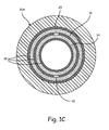
- FIG. 1C shows a cross-sectional view of portion 20A taken along line A-A of FIG. 1B .
- portion 20A is located within engine 22.
- Portion 20A defines fuel passage 29 through which fuel 12 flows.
- fuel metering valve 30 (shown schematically) and multi-plate capacitor device 32.
- Metering valve 30 has a first end 30A on an upstream end of metering valve 30 and a second end 30B on a downstream end of metering valve 30.
- Metering valve 30 can be utilized to measure a volumetric flow of fuel 12 as is known in the art.
- Capacitor device 32 includes first current sensing electrode plate 34 and second voltage driven electrode plate 36 configured concentrically around first plate 34.
- Plate 34 is in communication with connecting lead 34L, which is joined to header pin 34P which passes through glass header 34H disposed in a wall of portion 20A.
- Plate 36 is in communication with connecting lead 36L, which is joined to header pin 36P which passes through glass header 36H disposed in the wall of portion 20A.
- Insulating material 38 is disposed concentrically between fuel passage 29 and second plate 36, second plate 36 and first plate 34, and first plate 34 and fuel 12 passing through passage 29.
- Insulating material 38 is present at an angular range between first plate 34 and second plate 36 less than 360°, such that a gap or fuel entry 40 between first plate 34 and second plate 36 is defined both radially between plates 34 and 36 and axially along a distance of plates 34 and 36.
- Capacitor device 32 functions to measure a capacitance of fuel 12, and thus a dielectric constant of fuel 12 at portion 20A.
- Fuel 12 enters through end 30A of metering valve 30 and is dispelled out end 30B. A majority of fuel 12 then passes through a center of fuel passage 29. However, a portion 12P of fuel 12 from end 30B flows into an upstream end of gap or fuel entry 40.
- Gap 40 is sized to have a cross-sectional area at any axial location along gap 40 large enough to allow debris or particulate normally present within fuel 12P to pass through gap 40 without causing blockage of gap 40.
- gap 40 is sized to have a cross-sectional area small enough to slow down a flow of fuel 12P passing through gap 40, relative to a flow of fuel 12 passing through a center of fuel passage 29 and bypassing gap 40.
- fuel 12P passes through gap 40, fuel 12P is in contact with plate 34 on one side and plate 36 on another side such that fuel 12P serves as the dielectric allowing a capacitance of fuel 12P to be measured.
- This measured capacitance of fuel 12P within portion 20A can then be used to find the dielectric constant of fuel 12 (relative to air) at portion 20A.
- Fuel 12P is then dispelled at a downstream end of gap 40 where it merges with fuel 12 passing through the center of fuel passage 29. All fuel 12 can then be passed, for example, to combustor 24.
- the described configuration of device 32 provides particular benefits.
- the concentric configuration of plates 34 and 36 allows device 32 to obtain a greater capacitive response while reducing an area taken up by plates 34 and 36 on an upstream end such that fluidic impedance on fuel 12 flowing through the center of fuel passage 29 is minimized.
- prior parallel electrode plate capacitors generate less capacitive response and create more impedance to the flow of fuel 12.
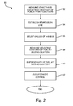
- FIG. 2 illustrates a flow diagram of method 50 for accurately determining fuel 12 density. To begin, dielectric constant versus density characteristics of fuel 12 can be obtained.
- steps 52, 54, and 56 can be used to obtain dielectric constant versus density characteristics at the first location.
- the first location will be discussed here as fuel tank 14, but in other embodiments other locations suitable for obtaining dielectric constant versus density characteristics can be used.
- Both density D 1 and dielectric constant K 1 of fuel 12 are measured at fuel tank 14 (step 52). Density D 1 of fuel 12 can be measured at fuel tank 14 using density sensor 16 and the dielectric constant K 1 of fuel 12 can be measured at fuel tank 14 using dielectric sensor 18, as described with respect to FIG. 1A . Density D 1 and dielectric constant K 1 measured at fuel tank 14 can then be used as values for D and K in the expression (I).
- a regression line for a plot of dielectric constant versus density can be established for the particular fuel 12 (step 54).
- D 1 and K 1 establish a point on the plot of dielectric constant versus density and the regression line is generated from the expression (I) so as to pass through the point D 1 , K 1 by adjusting values of A and B in the expression (I).
- values of constants A 1 and B 1 in the expression (I) can be selected as a function of the regression line passing through the point D 1 , K 1 (step 56).
- all variables in expression (I) have suitable values.
- dielectric constant versus density characteristics of fuel 12 at a first location e.g. fuel tank 14
- a dielectric constant K 2 of fuel 12 can be measured at a second location (step 58).
- the second location can be, for example, portion 20A of fuel line 20 where environmental conditions include higher temperatures and pressures than the first location (e.g. fuel tank 14).
- the second location can be selected as any other desired location remote from the first location and which is subjected to environmental conditions differing from environmental conditions at the first location.
- the environmental conditions can be too extreme to permit use of a densitometer or other type of density sensor to directly measure density of fuel 12.
- the dielectric constant K 2 can be measured within portion 20A downstream of metering valve 30 using device 32 as described with respect to FIGS. 1B and 1C .
- dielectric constant K 2 of fuel 12 at portion 20A can be used as K along with the selected values of A 1 and B 1 as a function of the regression line to solve the expression for D 2 .
- density D 2 of fuel 12 is inferred at portion 20A using the measured dielectric constant K 2 of fuel 12 at portion 20A and the dielectric constant versus density characteristics of fuel 12 determined at the first location. This provides an accurate value for density D 2 of fuel 12 at portion 20A independent of a temperature.
- engine 22 control can be adjusted based on the accurate measurement of density D 2 of fuel 12 at portion 20A (step 62).
- the ability to accurately measure density D 2 independent of temperature at portion 20A is significant because this location is where a value of fuel 12 density is most critical for use in efficient engine 22 control. Even slight inaccuracies in the value of fuel 12 density at portion 20A can result in substantial inefficiencies in engine 22 control.
- an accurate value of the density of fuel 12 and the volumetric flow of fuel 12 obtained from metering valve 30, a mass flow of fuel 12 at portion 20A can be calculated and used in engine 22 control.
- a method for accurately determining a density of a fuel comprising: obtaining dielectric constant versus density characteristics of the fuel at a first location; measuring a dielectric constant of the fuel at a second location, wherein environmental conditions at the second location differ from environmental conditions at the first location; and inferring the density of the fuel at the second location using the dielectric constant of the fuel at the second location and the dielectric constant versus density characteristics of the fuel at the first location.
- the method of the preceding paragraph can optionally include, additionally and/or alternatively, the following techniques, steps, features and/or configurations:
- Obtaining the dielectric constant versus density characteristics of the fuel at the first location comprises: measuring a density of the fuel at the first location; using the density measured at the first location as D in the expression; measuring a dielectric constant of the fuel at the first location; using the dielectric constant measured at the first location as K in the expression; establishing a regression line for a plot of dielectric constant versus density based on measured values of density and dielectric constant at the first location; and selecting values of constants A and B as a function of the regression line.
- Inferring the density of the fuel at the second location using the dielectric constant of the fuel at the second location and the dielectric constant versus density characteristics of the fuel at the first location comprises: using the measured dielectric constant of the fuel at the second location as the dielectric constant of the fuel K in the expression; and using the selected values of constants A and B as the constants A and B in the expression.
- the dielectric constant of the fuel at the second location is measured by passing fuel from the first location through a gap between concentric electrode plates at the second location.
- Obtaining dielectric constant versus density characteristics of the fuel at a first location comprises obtaining dielectric constant versus density characteristics of the fuel in a fuel tank external to an engine.
- Determining the density of the fuel at the second location comprises determining the density of the fuel at or near a fuel metering valve in a fuel line within an engine.
- Measuring the dielectric constant of the fuel at the second location comprises measuring the dielectric constant of the fuel passing through a fuel line within an engine downstream of a fuel metering valve.
- An assembly used for determining a density of a fuel comprising: a fuel line through which a fuel is passed and located at least partially within an engine; a fuel metering valve located within the fuel line and configured to receive the fuel through a first end and dispel the fuel through a second end; and a multi-plate capacitor device located within the fuel line through which the fuel passes, the device comprising: a first current sensing electrode plate; a second voltage driven electrode plate configured concentrically around the first plate; and an insulating material configured concentrically between the first plate and the second plate, wherein the insulating material is present in an angular range between the first plate and the second plate less than 360° such that at least one gap is defined radially between the first plate and the second plate and along an axial distance of the first plate and the second plate, and wherein the at least one gap receives fuel at an upstream end and dispels fuel at a downstream end such that a first measurement of capacitance of the fuel can be obtained across the at least one gap.
- the assembly of the preceding paragraph can optionally include, additionally and/or alternatively, any one or more of the following features, configurations and/or additional components:
- the at least one gap has a cross-sectional area at any axial location along the gap large enough to pass debris through and small enough to slow down a flow of fuel relative to a flow of fuel passing through the fuel line and bypassing the gap.
- Environmental conditions at the multi-plate capacitor device which include a temperature greater than a temperature at the fuel tank and a pressure greater than a pressure at the fuel tank.
Landscapes
- Chemical & Material Sciences (AREA)
- General Physics & Mathematics (AREA)
- Physics & Mathematics (AREA)
- Health & Medical Sciences (AREA)
- Life Sciences & Earth Sciences (AREA)
- Analytical Chemistry (AREA)
- Pathology (AREA)
- Immunology (AREA)
- General Health & Medical Sciences (AREA)
- Biochemistry (AREA)
- Engineering & Computer Science (AREA)
- Fluid Mechanics (AREA)
- Chemical Kinetics & Catalysis (AREA)
- Medicinal Chemistry (AREA)
- Food Science & Technology (AREA)
- Electrochemistry (AREA)
- Oil, Petroleum & Natural Gas (AREA)
- General Chemical & Material Sciences (AREA)
- Combustion & Propulsion (AREA)
- Investigating Or Analyzing Materials By The Use Of Electric Means (AREA)
Abstract
Description
- The present embodiments relate generally to fluid-gauging assemblies and methods, and more particularly to fluid-gauging assemblies and methods for determining properties of fuel used in a gas turbine engine.
- In one exemplary application, a gas turbine engine can be used on an aircraft. In aircraft engine control, it can be necessary to know a value of a mass flow of fuel due to mass flow's direct effect on engine thrust. Prior fuel gauging techniques have obtained fuel mass flow values using moving components within the engine. For example, two impellers connected by a shaft with a known spring constant have been used to find fuel mass flow given the proportional relation between torque on the shaft (and thus impeller angular displacement) and fuel mass flow. However, fuel-gauging techniques which utilize moving components are undesirable.
- Fuel mass flow is equal to the product of fuel volumetric flow and fuel density. Fuel volumetric flow is readily obtained using known techniques. Thus, an accurate measurement of fuel density can yield fuel mass flow. Prior fuel gauging techniques have attempted to accurately determine fuel density by either directly measuring fuel density in a fuel tank external to the engine using some form of a densitometer, or measuring a dielectric constant of the fuel in the fuel tank external to the engine and then deducing fuel density using this measured dielectric constant in the fuel tank. However, such techniques do not provide an accurate enough measurement of fuel density to allow for precise, economical aircraft engine control.
- One embodiment includes a method for accurately determining a density of a fuel. The method includes obtaining dielectric constant versus density characteristics of the fuel at a first location and measuring a dielectric constant of the fuel at a second location. The environmental conditions at the second location differ from environmental conditions at the first location. Density of the fuel at the second location is inferred using the dielectric constant of the fuel at the second location and the dielectric constant versus density characteristics of the fuel at the first location.
- Another embodiment includes an assembly used for determining a density of a fuel. The assembly includes a fuel line through which a fuel is passed and located at least partially within an engine, a fuel metering valve located within the fuel line and configured to receive the fuel through a first end and dispel the fuel through a second end, and a multi-plate capacitor device located within the fuel line through which the fuel passes. The device includes a first current sensing electrode plate, a second voltage driven electrode plate configured concentrically around the first plate, and an insulating material configured concentrically between the first plate and the second plate. The insulating material is present in an angular range between the first plate and the second plate less than 360° such that at least one gap is defined radially between the first plate and the second plate and along an axial distance of the first plate and the second plate. The at least one gap receives fuel at an upstream end and dispels fuel at a downstream end such that a first measurement of capacitance of the fuel can be obtained across the at least one gap.
-
-
FIG. 1A is a schematic diagram of an assembly on an aircraft for determining a density of a fuel. -
FIG. 1B is a cross-sectional view of a portion of a fuel line of the assembly ofFIG. 1A with a metering valve and a multi-plate capacitor device. -
FIG. 1C is a cross-sectional view of the portion of the fuel line ofFIG. 1B taken along line A-A. -
FIG. 2 is a flow diagram illustrating a method for accurately determining fuel density. - While the above-identified drawing figures set forth multiple embodiments of the invention, other embodiments are also contemplated. In all cases, this disclosure presents the invention by way of representation and not limitation. It should be understood that numerous other modifications and embodiments can be devised by those skilled in the art, which fall within the scope of the principles of the invention. The figures may not be drawn to scale, and applications and embodiments of the present invention may include features and components not specifically shown in the drawings.
- The present embodiments provide assemblies and methods for accurately determining a density of a fuel.
FIG 1A is a schematic diagram of anaircraft 9 which includes anassembly 10 for accurately determining a density offuel 12. -
Assembly 10 includesfuel 12 which is stored infuel tank 14. In one embodiment,fuel 12 can be, for example, a kerosene-based or kerosene-like fuel such as Jet A, Jet A1, Jet B, JP 4, JP 5, or JP 8, with or without additives such as stabilizers, etc.Fuel tank 14 is supplied withfuel 12 and serves to storefuel 12. In the illustrated embodiment, disposed inside offuel tank 14 aredensity sensor 16 anddielectric sensor 18. As shown,density sensor 16 anddielectric sensor 18 are mounted on a bottom offuel tank 14 such that thesesensors fuel 12 regardless of whether a volume offuel tank 14 is near full or near empty offuel 12. However, inother embodiments sensors fuel tank 14 at various other locations withinfuel tank 14.Density sensor 16 can be, for example, a form of densitometer or any other device suitable for accurately measuring a density offuel 12 withinfuel tank 14.Dielectric sensor 18 can be, for example, a capacitor or any other device suitable for accurately measuring a dielectric constant (i.e. relative permittivity) of fuel 12 (i.e. wherefuel 12 is the dielectric and the dielectric constant is relative to air). -
Assembly 10 also includesfuel line 20, which is in fluid communication with bothfuel tank 14 on one end andengine 22, on another end.Fuel line 20 serves to communicatefuel 12 fromfuel tank 14 toengine 22. In one exemplary application,engine 22 is a gas turbine engine and can be mounted toaircraft 9 for powering and propellingaircraft 9. Aportion 20A offuel line 20 is withinengine 22 and in fluid communication withcombustor 24. Withincombustor 24,fuel 12 is mixed with compressed air and ignited producing hot combustion gasses from whichengine 22 extracts energy. Environmental conditions withinengine 22, and thus environmental conditions atportion 20A offuel line 20, differ from environmental conditions external toengine 22, such as withinfuel tank 14. For instance, both a temperature and a pressure withinengine 22 can be significantly greater than a temperature and pressure external toengine 22, such as withinfuel tank 14. Additionally, operating conditions withinengine 22 can vary at different times resulting in different environmental conditions, such as temperature and pressure, withinengine 22 at a given time. Thus, asfuel 12 is communicated throughoutassembly 10fuel 12 will be subject to different temperatures and pressures. - Some prior assemblies and methods for determining a density of
fuel 12 have utilized only density sensor 16 (and not dielectric sensor 18) withinfuel tank 14. However, becausefuel 12 will be subject to varying temperatures and pressures withinassembly 10, a density offuel 12 will vary throughoutassembly 10. In fact,fuel 12 density can vary with temperature more than 25% over the typical operating range of mostgas turbine engines 22. Consequently, a measurement of the density offuel 12 usingdensity sensor 16 withinfuel tank 14 will not provide an accurate measurement of the density offuel 12 atother assembly 10 locations, such asportion 20A offuel line 20. - Other prior assemblies and methods for determining a density of
fuel 12 have utilizeddielectric sensor 18 to measure a dielectric constant offuel 12 withinfuel tank 14. As known to those in the art of fuel-gauging, a relationship between the dielectric constant offuel 12 and density offuel 12 is defined by the expression:
where D is the density offuel 12, K is the dielectric constant offuel 12, and A and B are constants based on the type of fuel 12 (e.g. Jet A). However, becausefuel 12 can be subject to different environmental conditions (e.g., different temperatures and pressures) withinassembly 10, the dielectric constant offuel 12 will vary throughoutassembly 10. As a result, a measured dielectric constant offuel 12 withinfuel tank 14, for example, will not provide an accurate measurement of a dielectric constant offuel 12 at other locations withinassembly 10 which are exposed to different environmental conditions, such as atportion 20A. Therefore, measuring dielectric constant offuel 12 at a first location withinassembly 10 and using the expression to obtain a value of the density offuel 12 at the first location will not provide an accurate value for the density offuel 12 at a second location subject to different environmental conditions. - To further complicate matters, a particular type of fuel 12 (e.g. Jet A) is not consistent from sample to sample, and therefore the dielectric properties of that particular type of
fuel 12 are not consistent (i.e. Jet A, for example, can have two different dielectric constant values at the same temperature). This inconsistency within a single type offuel 12 is due to the fact that the proportions of olefin, paraffin, napthene, and aromatic, hydrocarbons which make upfuel 12, are not strictly controlled and indeed vary according to the geological source of the oil, local refining practices, and the type offuel 12 being produced. As a result, a particular type offuel 12 supplied tofuel tank 14 at one location can have dielectric properties which differ from that same particular type of fuel supplied tofuel tank 14 at a second location. Furthermore, in many cases the same type offuel 12 from two different locations can end up mixed together insidefuel tank 14. Thus, using the dielectric constant offuel 12 measured infuel tank 14 does not provide an accurate calculation offuel 12 density. - Such inaccuracies in the measurement of the density of
fuel 12 can lead to, among others, inefficiencies in control ofengine 22. The present embodiments provide assemblies and methods for accurately determining the density offuel 12, and in particular accurately determining the density offuel 12 at a location where the value of the density offuel 12 is most useful in engine control. -
FIGS. 1B and1C illustrate detailed views ofportion 20A offuel line 20.FIG. 1B illustrates a cross-sectional view ofportion 20A.FIG. 1C shows a cross-sectional view ofportion 20A taken along line A-A ofFIG. 1B . - As described previously,
portion 20A is located withinengine 22.Portion 20A definesfuel passage 29 through whichfuel 12 flows. Included withinportion 20A are fuel metering valve 30 (shown schematically) andmulti-plate capacitor device 32.Metering valve 30 has afirst end 30A on an upstream end ofmetering valve 30 and asecond end 30B on a downstream end ofmetering valve 30.Metering valve 30 can be utilized to measure a volumetric flow offuel 12 as is known in the art. -
Capacitor device 32 includes first currentsensing electrode plate 34 and second voltage drivenelectrode plate 36 configured concentrically aroundfirst plate 34.Plate 34 is in communication with connecting lead 34L, which is joined toheader pin 34P which passes throughglass header 34H disposed in a wall ofportion 20A.Plate 36 is in communication with connecting lead 36L, which is joined toheader pin 36P which passes throughglass header 36H disposed in the wall ofportion 20A. Insulatingmaterial 38 is disposed concentrically betweenfuel passage 29 andsecond plate 36,second plate 36 andfirst plate 34, andfirst plate 34 andfuel 12 passing throughpassage 29. Insulatingmaterial 38 is present at an angular range betweenfirst plate 34 andsecond plate 36 less than 360°, such that a gap orfuel entry 40 betweenfirst plate 34 andsecond plate 36 is defined both radially betweenplates plates -
Capacitor device 32 functions to measure a capacitance offuel 12, and thus a dielectric constant offuel 12 atportion 20A.Fuel 12 enters throughend 30A ofmetering valve 30 and is dispelled outend 30B. A majority offuel 12 then passes through a center offuel passage 29. However, aportion 12P offuel 12 fromend 30B flows into an upstream end of gap orfuel entry 40.Gap 40 is sized to have a cross-sectional area at any axial location alonggap 40 large enough to allow debris or particulate normally present withinfuel 12P to pass throughgap 40 without causing blockage ofgap 40. Yet,gap 40 is sized to have a cross-sectional area small enough to slow down a flow offuel 12P passing throughgap 40, relative to a flow offuel 12 passing through a center offuel passage 29 and bypassinggap 40. Asfuel 12P passes throughgap 40,fuel 12P is in contact withplate 34 on one side andplate 36 on another side such thatfuel 12P serves as the dielectric allowing a capacitance offuel 12P to be measured. This measured capacitance offuel 12P withinportion 20A can then be used to find the dielectric constant of fuel 12 (relative to air) atportion 20A.Fuel 12P is then dispelled at a downstream end ofgap 40 where it merges withfuel 12 passing through the center offuel passage 29. Allfuel 12 can then be passed, for example, tocombustor 24. - The described configuration of
device 32 provides particular benefits. The concentric configuration ofplates device 32 to obtain a greater capacitive response while reducing an area taken up byplates fuel 12 flowing through the center offuel passage 29 is minimized. As compared todevice 32, prior parallel electrode plate capacitors generate less capacitive response and create more impedance to the flow offuel 12. -
FIG. 2 illustrates a flow diagram ofmethod 50 for accurately determiningfuel 12 density. To begin, dielectric constant versus density characteristics offuel 12 can be obtained. - In one embodiment, steps 52, 54, and 56 can be used to obtain dielectric constant versus density characteristics at the first location. The first location will be discussed here as
fuel tank 14, but in other embodiments other locations suitable for obtaining dielectric constant versus density characteristics can be used. Both density D1 and dielectric constant K1 offuel 12 are measured at fuel tank 14 (step 52). Density D1 offuel 12 can be measured atfuel tank 14 usingdensity sensor 16 and the dielectric constant K1 offuel 12 can be measured atfuel tank 14 usingdielectric sensor 18, as described with respect toFIG. 1A . Density D1 and dielectric constant K1 measured atfuel tank 14 can then be used as values for D and K in the expression (I). - Based on the measured D1 and K1 values at
fuel tank 14, a regression line for a plot of dielectric constant versus density can be established for the particular fuel 12 (step 54). D1 and K1 establish a point on the plot of dielectric constant versus density and the regression line is generated from the expression (I) so as to pass through the point D1, K1 by adjusting values of A and B in the expression (I). In other words, values of constants A1 and B1 in the expression (I) can be selected as a function of the regression line passing through the point D1, K1 (step 56). At this point, all variables in expression (I) have suitable values. Thus, dielectric constant versus density characteristics offuel 12 at a first location (e.g. fuel tank 14) have been determined. - Next, a dielectric constant K2 of
fuel 12 can be measured at a second location (step 58). The second location can be, for example,portion 20A offuel line 20 where environmental conditions include higher temperatures and pressures than the first location (e.g. fuel tank 14). In further embodiments, the second location can be selected as any other desired location remote from the first location and which is subjected to environmental conditions differing from environmental conditions at the first location. At a location such asportion 20A, the environmental conditions can be too extreme to permit use of a densitometer or other type of density sensor to directly measure density offuel 12. The dielectric constant K2 can be measured withinportion 20A downstream ofmetering valve 30 usingdevice 32 as described with respect toFIGS. 1B and1C . - Once
fuel 12 dielectric constant K2 has been measured atportion 20A, density D2 offuel 12 atportion 20A can be accurately inferred (step 60). In the expression (I), dielectric constant K2 offuel 12 atportion 20A can be used as K along with the selected values of A1 and B1 as a function of the regression line to solve the expression for D2. The expression would look as follows:
- In other words, density D2 of
fuel 12 is inferred atportion 20A using the measured dielectric constant K2 offuel 12 atportion 20A and the dielectric constant versus density characteristics offuel 12 determined at the first location. This provides an accurate value for density D2 offuel 12 atportion 20A independent of a temperature. - Finally,
engine 22 control can be adjusted based on the accurate measurement of density D2 offuel 12 atportion 20A (step 62). Importantly, the ability to accurately measure density D2 independent of temperature atportion 20A is significant because this location is where a value offuel 12 density is most critical for use inefficient engine 22 control. Even slight inaccuracies in the value offuel 12 density atportion 20A can result in substantial inefficiencies inengine 22 control. With an accurate value of the density offuel 12 and the volumetric flow offuel 12, obtained frommetering valve 30, a mass flow offuel 12 atportion 20A can be calculated and used inengine 22 control. - The following are non-exclusive descriptions of possible embodiments of the present invention.
- A method for accurately determining a density of a fuel, the method comprising: obtaining dielectric constant versus density characteristics of the fuel at a first location; measuring a dielectric constant of the fuel at a second location, wherein environmental conditions at the second location differ from environmental conditions at the first location; and inferring the density of the fuel at the second location using the dielectric constant of the fuel at the second location and the dielectric constant versus density characteristics of the fuel at the first location.
- The method of the preceding paragraph can optionally include, additionally and/or alternatively, the following techniques, steps, features and/or configurations:
- The dielectric constant versus density characteristics of the fuel at the first location are obtained in accordance substantially with the following expression:

where D is the density of the fuel, K is the dielectric constant of the fuel, and A and B are constants based on the type of fuel. - Obtaining the dielectric constant versus density characteristics of the fuel at the first location comprises: measuring a density of the fuel at the first location; using the density measured at the first location as D in the expression; measuring a dielectric constant of the fuel at the first location; using the dielectric constant measured at the first location as K in the expression; establishing a regression line for a plot of dielectric constant versus density based on measured values of density and dielectric constant at the first location; and selecting values of constants A and B as a function of the regression line.
- Inferring the density of the fuel at the second location using the dielectric constant of the fuel at the second location and the dielectric constant versus density characteristics of the fuel at the first location comprises: using the measured dielectric constant of the fuel at the second location as the dielectric constant of the fuel K in the expression; and using the selected values of constants A and B as the constants A and B in the expression.
- Passing fuel from the first location to the second location, wherein the environmental conditions at the first location include a temperature less than a temperature of the environmental conditions at the second location.
- The dielectric constant of the fuel at the second location is measured by passing fuel from the first location through a gap between concentric electrode plates at the second location.
- Obtaining dielectric constant versus density characteristics of the fuel at a first location comprises obtaining dielectric constant versus density characteristics of the fuel in a fuel tank external to an engine.
- Determining the density of the fuel at the second location comprises determining the density of the fuel at or near a fuel metering valve in a fuel line within an engine.
- Adjusting engine control based on the determination of the density of the fuel at or near the fuel metering valve.
- Measuring the dielectric constant of the fuel at the second location comprises measuring the dielectric constant of the fuel passing through a fuel line within an engine downstream of a fuel metering valve.
- An assembly used for determining a density of a fuel, the assembly comprising: a fuel line through which a fuel is passed and located at least partially within an engine; a fuel metering valve located within the fuel line and configured to receive the fuel through a first end and dispel the fuel through a second end; and a multi-plate capacitor device located within the fuel line through which the fuel passes, the device comprising: a first current sensing electrode plate; a second voltage driven electrode plate configured concentrically around the first plate; and an insulating material configured concentrically between the first plate and the second plate, wherein the insulating material is present in an angular range between the first plate and the second plate less than 360° such that at least one gap is defined radially between the first plate and the second plate and along an axial distance of the first plate and the second plate, and wherein the at least one gap receives fuel at an upstream end and dispels fuel at a downstream end such that a first measurement of capacitance of the fuel can be obtained across the at least one gap.
- The assembly of the preceding paragraph can optionally include, additionally and/or alternatively, any one or more of the following features, configurations and/or additional components:
- The device is configured such that the upstream end of the at least one gap receives fuel from the second end of the fuel metering valve.
- The at least one gap has a cross-sectional area at any axial location along the gap large enough to pass debris through and small enough to slow down a flow of fuel relative to a flow of fuel passing through the fuel line and bypassing the gap.
- A fuel tank located external to the engine containing a portion of the fuel; the fuel line in fluid communication with the fuel tank to deliver fuel from the fuel tank to the fuel metering valve located within the fuel line; a density sensor located at least partially within the fuel tank; and a dielectric sensor located at least partially within the fuel tank to obtain a second measurement of capacitance of the fuel.
- Environmental conditions at the multi-plate capacitor device which include a temperature greater than a temperature at the fuel tank and a pressure greater than a pressure at the fuel tank.
- Any relative terms or terms of degree used herein, such as "generally", "substantially", "approximately", and the like, should be interpreted in accordance with and subject to any applicable definitions or limits expressly stated herein. In all instances, any relative terms or terms of degree used herein should be interpreted to broadly encompass any relevant disclosed embodiments as well as such ranges or variations as would be understood by a person of ordinary skill in the art in view of the entirety of the present disclosure, such as to encompass ordinary manufacturing tolerance variations, incidental alignment variations, temporary alignment or shape variations induced by operational conditions, and the like.
- While the invention has been described with reference to an exemplary embodiment(s), it will be understood by those skilled in the art that various changes may be made and equivalents may be substituted for elements thereof without departing from the scope of the invention. In addition, many modifications may be made to adapt a particular situation or material to the teachings of the invention without departing from the essential scope thereof. Therefore, it is intended that the invention not be limited to the particular embodiment(s) disclosed, but that the invention will include all embodiments falling within the scope of the appended claims.
Claims (15)
- A method for accurately determining a density of a fuel (12), the method comprising:obtaining dielectric constant versus density characteristics of the fuel (12) at a first location;measuring a dielectric constant of the fuel (12) at a second location, wherein environmental conditions at the second location differ from environmental conditions at the first location; andinferring the density of the fuel (12) at the second location using the dielectric constant of the fuel (12) at the second location and the dielectric constant versus density characteristics of the fuel (12) at the first location.
- The method of claim 1, wherein the dielectric constant versus density characteristics of the fuel (12) at the first location are obtained in accordance substantially with the following expression:

where D is the density of the fuel, K is the dielectric constant of the fuel (12), and A and B are constants based on the type of fuel (12). - The method of claim 2, wherein obtaining the dielectric constant versus density characteristics of the fuel (12) at the first location comprises:measuring a density of the fuel (12) at the first location;using the density measured at the first location as D in the expression;measuring a dielectric constant of the fuel (12) at the first location;using the dielectric constant measured at the first location as K in the expression;establishing a regression line for a plot of dielectric constant versus density based on the measured values of density and dielectric constant at the first location; andselecting values of constants A and B as a function of the regression line.
- The method of claim 3, wherein inferring the density of the fuel (12) at the second location using the dielectric constant of the fuel (12) at the second location and the dielectric constant versus density characteristics of the fuel (12) at the first location comprises:using the measured dielectric constant of the fuel (12) at the second location as the dielectric constant of the fuel K in the expression; andusing the selected values of constants A and B as the constants A and B in the expression.
- The method of any preceding claim, further comprising:passing fuel (12) from the first location to the second location, wherein the environmental conditions at the first location include a temperature less than a temperature of the environmental conditions at the second location.
- The method of any preceding claim, wherein the dielectric constant of the fuel (12) at the second location is measured by passing fuel (12) from the first location through a gap (40) between concentric electrode plates (34, 36) at the second location.
- The method of any preceding claim, wherein obtaining dielectric constant versus density characteristics of the fuel (12) at a first location comprises obtaining dielectric constant versus density characteristics of the fuel (12) in a fuel tank (14) external to an engine (22).
- The method of any preceding claim, wherein determining the density of the fuel (12) at the second location comprises determining the density of the fuel (12) at or near a fuel metering valve (30) in a fuel line (20) within an/the engine (22).
- The method of claim 8, further comprising:adjusting engine control based on the determination of the density of the fuel (12) at or near the fuel metering valve (30).
- The method of any preceding claim, wherein measuring the dielectric constant of the fuel (12) at the second location comprises measuring the dielectric constant of the fuel (12) passing through a/the fuel line (20) within an/the engine (22) downstream of a/the fuel metering valve (30).
- An assembly (10) used for determining a density of a fuel (12), the assembly (10) comprising:a fuel line (20) through which a fuel (12) is passed and located at least partially within an engine (22);a fuel metering valve (30) located within the fuel line (20) and configured to receive the fuel (12) through a first end (30A) and dispel the fuel (12) through a second end (30B); anda multi-plate capacitor device (32) located within the fuel line (20) through which the fuel passes, the device (32) comprising:a first current sensing electrode plate (34);a second voltage driven electrode plate (36) configured concentrically around the first plate (34); andan insulating material (38) configured concentrically between the first plate (34) and the second plate (36), wherein the insulating material (38) is present in an angular range between the first plate (34) and the second plate (36) less than 360° such that at least one gap (40) is defined radially between the first plate (34) and the second plate (36) and along an axial distance of the first plate (34) and the second plate (36), and wherein the at least one gap (40) receives fuel (12) at an upstream end and dispels fuel at a downstream end such that a first measurement of capacitance of the fuel (12) can be obtained across the at least one gap (40).
- The assembly of claim 11, wherein the device (32) is configured such that the upstream end of the at least one gap (40) receives fuel (12) from the second end (30B) of the fuel metering valve (30).
- The assembly of claim 11 or 12, wherein the at least one gap (40) has a cross-sectional area at any axial location along the gap (40) large enough to pass debris through and small enough to slow down a flow of fuel (12P) relative to a flow of fuel (12) passing through the fuel line (20) and bypassing the gap (40).
- The assembly of claim 11, 12 or 13, further comprising:a fuel tank (14) located external to the engine (22) containing a portion of the fuel (12);the fuel line (20) in fluid communication with the fuel tank (14) to deliver fuel (12) from the fuel tank (14) to the fuel metering valve (30) located within the fuel line (30);a density sensor (16) located at least partially within the fuel tank (14); anda dielectric sensor (18) located at least partially within the fuel tank (14) to obtain a second measurement of capacitance of the fuel (12).
- The assembly of any of claims 11 to 14, further comprising environmental conditions at the multi-plate capacitor device (32) which include a temperature greater than a temperature at the fuel tank (14) and a pressure greater than a pressure at the fuel tank (14).
Applications Claiming Priority (1)
| Application Number | Priority Date | Filing Date | Title |
|---|---|---|---|
| US14/529,489 US9909967B2 (en) | 2014-10-31 | 2014-10-31 | Fuel density determination |
Publications (3)
| Publication Number | Publication Date |
|---|---|
| EP3023751A2 true EP3023751A2 (en) | 2016-05-25 |
| EP3023751A3 EP3023751A3 (en) | 2016-09-28 |
| EP3023751B1 EP3023751B1 (en) | 2017-11-29 |
Family
ID=54364132
Family Applications (1)
| Application Number | Title | Priority Date | Filing Date |
|---|---|---|---|
| EP15192089.9A Active EP3023751B1 (en) | 2014-10-31 | 2015-10-29 | Fuel density determination |
Country Status (4)
| Country | Link |
|---|---|
| US (1) | US9909967B2 (en) |
| EP (1) | EP3023751B1 (en) |
| BR (1) | BR102015027589B1 (en) |
| CA (1) | CA2899503C (en) |
Cited By (3)
| Publication number | Priority date | Publication date | Assignee | Title |
|---|---|---|---|---|
| GB2587685A (en) * | 2019-10-02 | 2021-04-07 | Advanced Mobility Res And Development Ltd | Systems, arrangements, structures and methods for aircraft |
| FR3110195A1 (en) * | 2020-05-18 | 2021-11-19 | Safran Aerosystems | Aircraft comprising in its fuel tank a chamber fitted with a sensor |
| FR3110196A1 (en) * | 2020-05-18 | 2021-11-19 | Safran Aerosystems | Method for determining characteristics of a fuel supplied to an aircraft engine |
Families Citing this family (6)
| Publication number | Priority date | Publication date | Assignee | Title |
|---|---|---|---|---|
| KR20150136640A (en) * | 2014-05-27 | 2015-12-08 | 한국전자통신연구원 | Apparatus and method of discriminating the reformulated fuel |
| US10145834B2 (en) | 2016-07-19 | 2018-12-04 | The Boeing Company | Systems and methods for non-flammable indication of incendivity |
| US10532822B2 (en) * | 2017-01-25 | 2020-01-14 | The Boeing Company | Gas-flammability sensing systems and methods |
| US10442545B2 (en) * | 2017-04-18 | 2019-10-15 | Simmonds Precision Products, Inc. | Liquid measurement system for a tank |
| FR3069021B1 (en) | 2017-07-13 | 2019-07-26 | Safran Aircraft Engines | FUEL DOSING SYSTEM AND METHOD COMPRISING VARIABILITY OF FUEL DENSITY |
| FR3090861B1 (en) * | 2018-12-19 | 2021-05-14 | Airbus Operations Sas | METHOD FOR CALIBRATION OF A MEASURING DEVICE OF A FUEL MASS OF A TANK |
Family Cites Families (10)
| Publication number | Priority date | Publication date | Assignee | Title |
|---|---|---|---|---|
| US3635084A (en) | 1969-08-28 | 1972-01-18 | Simmonds Precision Products | Mass fuel flow measurement system |
| US3739635A (en) | 1971-05-12 | 1973-06-19 | Simmonds Precision Products | Fuel management system |
| US4262531A (en) | 1978-10-02 | 1981-04-21 | Smiths Industries Limited | Fluid-gauging methods and systems |
| US4258422A (en) * | 1979-05-04 | 1981-03-24 | Honeywell Inc. | Liquid gaging system |
| US5265460A (en) | 1991-04-09 | 1993-11-30 | Simmonds Precision Products, Inc. | Density determination of aircraft fuel based on the sensed temperature velocity of sound, and dielectric constant of the fuel |
| US7983856B2 (en) * | 2007-10-12 | 2011-07-19 | Eldec Corporation | Flow meter |
| US8281655B2 (en) * | 2009-04-03 | 2012-10-09 | Eaton Corporation | Fuel gauging system utilizing a digital fuel gauging probe |
| US8515694B1 (en) | 2009-04-09 | 2013-08-20 | The Boeing Company | Methods and systems for gauging multiple hydrocarbon fuel mixtures |
| EP2330393B1 (en) | 2009-12-04 | 2013-04-03 | Parker Hannifin Corp. | In-line Fuel Properties Measurement Unit |
| US8677819B2 (en) * | 2011-04-18 | 2014-03-25 | Parker-Hannifin Corporation | In-line fuel properties measurement unit |
-
2014
- 2014-10-31 US US14/529,489 patent/US9909967B2/en active Active
-
2015
- 2015-08-04 CA CA2899503A patent/CA2899503C/en active Active
- 2015-10-29 EP EP15192089.9A patent/EP3023751B1/en active Active
- 2015-10-30 BR BR102015027589-7A patent/BR102015027589B1/en active IP Right Grant
Non-Patent Citations (1)
| Title |
|---|
| None |
Cited By (9)
| Publication number | Priority date | Publication date | Assignee | Title |
|---|---|---|---|---|
| GB2587685A (en) * | 2019-10-02 | 2021-04-07 | Advanced Mobility Res And Development Ltd | Systems, arrangements, structures and methods for aircraft |
| FR3110195A1 (en) * | 2020-05-18 | 2021-11-19 | Safran Aerosystems | Aircraft comprising in its fuel tank a chamber fitted with a sensor |
| FR3110196A1 (en) * | 2020-05-18 | 2021-11-19 | Safran Aerosystems | Method for determining characteristics of a fuel supplied to an aircraft engine |
| WO2021234258A1 (en) * | 2020-05-18 | 2021-11-25 | Safran Aerosystems | Aircraft comprising, in its fuel tank, a chamber provided with a sensor |
| WO2021234257A1 (en) * | 2020-05-18 | 2021-11-25 | Safran Aerosystems | Method for determining characteristics of a fuel supplied to an aircraft engine |
| CN115768974A (en) * | 2020-05-18 | 2023-03-07 | 赛峰航空系统公司 | Method for determining a property of a fuel supplied to an aircraft engine |
| CN115768974B (en) * | 2020-05-18 | 2024-09-27 | 赛峰航空系统公司 | Method for determining the properties of fuel supplied to an aircraft engine |
| US12320689B2 (en) | 2020-05-18 | 2025-06-03 | Safran Aerosystems | Method for determining characteristics of a fuel supplied to an aircraft engine |
| US12576983B2 (en) | 2020-05-18 | 2026-03-17 | Safran Aerosystems | Aircraft comprising, in its fuel tank, a chamber provided with a sensor |
Also Published As
| Publication number | Publication date |
|---|---|
| CA2899503A1 (en) | 2016-04-30 |
| BR102015027589B1 (en) | 2020-12-01 |
| CA2899503C (en) | 2022-10-04 |
| BR102015027589A2 (en) | 2016-05-24 |
| US9909967B2 (en) | 2018-03-06 |
| EP3023751A3 (en) | 2016-09-28 |
| US20160123860A1 (en) | 2016-05-05 |
| EP3023751B1 (en) | 2017-11-29 |
Similar Documents
| Publication | Publication Date | Title |
|---|---|---|
| EP3023751B1 (en) | Fuel density determination | |
| US9891085B2 (en) | Ultrasound fuel flow sensing and control | |
| KR101224362B1 (en) | Device for Measuring Two-phase Flow Phase Concentration, System and Method for Measuring Flow Parameters of Two-phase Flow | |
| EP2423647B1 (en) | Apparatus for use in determining a plurality of characteristics of a multiphase flow within a pipe | |
| EP2015056B1 (en) | Method and sensor for determining a significant value in combustibility terms of a gas mixture | |
| CN202522295U (en) | System for calibrating turbine flow meter under condition of large flow of low-temperature medium | |
| EP2713137A1 (en) | Target clearance measurement device | |
| CN101852636A (en) | Fuel Quantity Calculation Method for UAV Fuel Tank | |
| DE102014119556A1 (en) | Thermal flowmeter | |
| CN105954146A (en) | Portable multifunctional comprehensive oil liquid tester | |
| CN101861520B (en) | Method and apparatus for determining fuel composition in motor oil | |
| CN106556676A (en) | A kind of detection means and detection method for multi-channel gas | |
| US8886448B2 (en) | Method of providing a volume-mass law for fuel consumption | |
| US12264952B2 (en) | Ultrasonic fuel flow measuring systems and methods | |
| De Palma et al. | Low-cost capacitive sensor for oil-level monitoring in aircraft | |
| US10975777B2 (en) | Fuel metering unit | |
| CN105222855A (en) | A kind of fuel tank Height of oil measurement mechanism | |
| CN104748809A (en) | Intelligent metering instrument based on pressure regulator and metering method | |
| CN118148612A (en) | A device and method for measuring water content in wellhead liquid | |
| US20110307192A1 (en) | Mass flow metering system for aircraft applications | |
| EP2014609A1 (en) | Fuel dispenser and method of temperature compensation in a fuel dispenser | |
| CN106762160A (en) | A kind of novel fuel temperature compensation | |
| US2406179A (en) | Method and apparatus for measuring air entrainment | |
| US20100132431A1 (en) | Method for testing and calibrating a capacitive flex fuel sensor | |
| CN113490848B (en) | Pump device and method for determining the concentration of a substance inside a liquid |
Legal Events
| Date | Code | Title | Description |
|---|---|---|---|
| AK | Designated contracting states |
Kind code of ref document: A2 Designated state(s): AL AT BE BG CH CY CZ DE DK EE ES FI FR GB GR HR HU IE IS IT LI LT LU LV MC MK MT NL NO PL PT RO RS SE SI SK SM TR |
|
| AX | Request for extension of the european patent |
Extension state: BA ME |
|
| PUAI | Public reference made under article 153(3) epc to a published international application that has entered the european phase |
Free format text: ORIGINAL CODE: 0009012 |
|
| PUAL | Search report despatched |
Free format text: ORIGINAL CODE: 0009013 |
|
| AK | Designated contracting states |
Kind code of ref document: A3 Designated state(s): AL AT BE BG CH CY CZ DE DK EE ES FI FR GB GR HR HU IE IS IT LI LT LU LV MC MK MT NL NO PL PT RO RS SE SI SK SM TR |
|
| AX | Request for extension of the european patent |
Extension state: BA ME |
|
| RIC1 | Information provided on ipc code assigned before grant |
Ipc: G01N 33/22 20060101ALN20160819BHEP Ipc: G01N 9/00 20060101ALN20160819BHEP Ipc: G01F 1/86 20060101AFI20160819BHEP Ipc: G01N 27/22 20060101ALN20160819BHEP |
|
| STAA | Information on the status of an ep patent application or granted ep patent |
Free format text: STATUS: REQUEST FOR EXAMINATION WAS MADE |
|
| 17P | Request for examination filed |
Effective date: 20170324 |
|
| RBV | Designated contracting states (corrected) |
Designated state(s): AL AT BE BG CH CY CZ DE DK EE ES FI FR GB GR HR HU IE IS IT LI LT LU LV MC MK MT NL NO PL PT RO RS SE SI SK SM TR |
|
| GRAP | Despatch of communication of intention to grant a patent |
Free format text: ORIGINAL CODE: EPIDOSNIGR1 |
|
| STAA | Information on the status of an ep patent application or granted ep patent |
Free format text: STATUS: GRANT OF PATENT IS INTENDED |
|
| RIC1 | Information provided on ipc code assigned before grant |
Ipc: G01N 33/22 20060101ALN20170412BHEP Ipc: G01F 1/86 20060101AFI20170412BHEP Ipc: G01N 9/00 20060101ALN20170412BHEP Ipc: G01N 27/22 20060101ALN20170412BHEP Ipc: G01F 25/00 20060101ALI20170412BHEP |
|
| INTG | Intention to grant announced |
Effective date: 20170512 |
|
| GRAS | Grant fee paid |
Free format text: ORIGINAL CODE: EPIDOSNIGR3 |
|
| GRAA | (expected) grant |
Free format text: ORIGINAL CODE: 0009210 |
|
| STAA | Information on the status of an ep patent application or granted ep patent |
Free format text: STATUS: THE PATENT HAS BEEN GRANTED |
|
| RIN1 | Information on inventor provided before grant (corrected) |
Inventor name: MCBRIEN, GARY M. Inventor name: CROWNE, DAVID H. |
|
| AK | Designated contracting states |
Kind code of ref document: B1 Designated state(s): AL AT BE BG CH CY CZ DE DK EE ES FI FR GB GR HR HU IE IS IT LI LT LU LV MC MK MT NL NO PL PT RO RS SE SI SK SM TR |
|
| REG | Reference to a national code |
Ref country code: CH Ref legal event code: EP |
|
| REG | Reference to a national code |
Ref country code: AT Ref legal event code: REF Ref document number: 950802 Country of ref document: AT Kind code of ref document: T Effective date: 20171215 |
|
| REG | Reference to a national code |
Ref country code: IE Ref legal event code: FG4D |
|
| REG | Reference to a national code |
Ref country code: DE Ref legal event code: R096 Ref document number: 602015006322 Country of ref document: DE |
|
| REG | Reference to a national code |
Ref country code: NL Ref legal event code: MP Effective date: 20171129 |
|
| REG | Reference to a national code |
Ref country code: LT Ref legal event code: MG4D |
|
| REG | Reference to a national code |
Ref country code: AT Ref legal event code: MK05 Ref document number: 950802 Country of ref document: AT Kind code of ref document: T Effective date: 20171129 |
|
| PG25 | Lapsed in a contracting state [announced via postgrant information from national office to epo] |
Ref country code: LT Free format text: LAPSE BECAUSE OF FAILURE TO SUBMIT A TRANSLATION OF THE DESCRIPTION OR TO PAY THE FEE WITHIN THE PRESCRIBED TIME-LIMIT Effective date: 20171129 Ref country code: FI Free format text: LAPSE BECAUSE OF FAILURE TO SUBMIT A TRANSLATION OF THE DESCRIPTION OR TO PAY THE FEE WITHIN THE PRESCRIBED TIME-LIMIT Effective date: 20171129 Ref country code: NO Free format text: LAPSE BECAUSE OF FAILURE TO SUBMIT A TRANSLATION OF THE DESCRIPTION OR TO PAY THE FEE WITHIN THE PRESCRIBED TIME-LIMIT Effective date: 20180228 Ref country code: ES Free format text: LAPSE BECAUSE OF FAILURE TO SUBMIT A TRANSLATION OF THE DESCRIPTION OR TO PAY THE FEE WITHIN THE PRESCRIBED TIME-LIMIT Effective date: 20171129 Ref country code: SE Free format text: LAPSE BECAUSE OF FAILURE TO SUBMIT A TRANSLATION OF THE DESCRIPTION OR TO PAY THE FEE WITHIN THE PRESCRIBED TIME-LIMIT Effective date: 20171129 |
|
| PG25 | Lapsed in a contracting state [announced via postgrant information from national office to epo] |
Ref country code: LV Free format text: LAPSE BECAUSE OF FAILURE TO SUBMIT A TRANSLATION OF THE DESCRIPTION OR TO PAY THE FEE WITHIN THE PRESCRIBED TIME-LIMIT Effective date: 20171129 Ref country code: HR Free format text: LAPSE BECAUSE OF FAILURE TO SUBMIT A TRANSLATION OF THE DESCRIPTION OR TO PAY THE FEE WITHIN THE PRESCRIBED TIME-LIMIT Effective date: 20171129 Ref country code: AT Free format text: LAPSE BECAUSE OF FAILURE TO SUBMIT A TRANSLATION OF THE DESCRIPTION OR TO PAY THE FEE WITHIN THE PRESCRIBED TIME-LIMIT Effective date: 20171129 Ref country code: BG Free format text: LAPSE BECAUSE OF FAILURE TO SUBMIT A TRANSLATION OF THE DESCRIPTION OR TO PAY THE FEE WITHIN THE PRESCRIBED TIME-LIMIT Effective date: 20180228 Ref country code: RS Free format text: LAPSE BECAUSE OF FAILURE TO SUBMIT A TRANSLATION OF THE DESCRIPTION OR TO PAY THE FEE WITHIN THE PRESCRIBED TIME-LIMIT Effective date: 20171129 Ref country code: GR Free format text: LAPSE BECAUSE OF FAILURE TO SUBMIT A TRANSLATION OF THE DESCRIPTION OR TO PAY THE FEE WITHIN THE PRESCRIBED TIME-LIMIT Effective date: 20180301 |
|
| PG25 | Lapsed in a contracting state [announced via postgrant information from national office to epo] |
Ref country code: NL Free format text: LAPSE BECAUSE OF FAILURE TO SUBMIT A TRANSLATION OF THE DESCRIPTION OR TO PAY THE FEE WITHIN THE PRESCRIBED TIME-LIMIT Effective date: 20171129 |
|
| PG25 | Lapsed in a contracting state [announced via postgrant information from national office to epo] |
Ref country code: SK Free format text: LAPSE BECAUSE OF FAILURE TO SUBMIT A TRANSLATION OF THE DESCRIPTION OR TO PAY THE FEE WITHIN THE PRESCRIBED TIME-LIMIT Effective date: 20171129 Ref country code: DK Free format text: LAPSE BECAUSE OF FAILURE TO SUBMIT A TRANSLATION OF THE DESCRIPTION OR TO PAY THE FEE WITHIN THE PRESCRIBED TIME-LIMIT Effective date: 20171129 Ref country code: EE Free format text: LAPSE BECAUSE OF FAILURE TO SUBMIT A TRANSLATION OF THE DESCRIPTION OR TO PAY THE FEE WITHIN THE PRESCRIBED TIME-LIMIT Effective date: 20171129 Ref country code: CY Free format text: LAPSE BECAUSE OF FAILURE TO SUBMIT A TRANSLATION OF THE DESCRIPTION OR TO PAY THE FEE WITHIN THE PRESCRIBED TIME-LIMIT Effective date: 20171129 Ref country code: CZ Free format text: LAPSE BECAUSE OF FAILURE TO SUBMIT A TRANSLATION OF THE DESCRIPTION OR TO PAY THE FEE WITHIN THE PRESCRIBED TIME-LIMIT Effective date: 20171129 |
|
| REG | Reference to a national code |
Ref country code: DE Ref legal event code: R097 Ref document number: 602015006322 Country of ref document: DE |
|
| PG25 | Lapsed in a contracting state [announced via postgrant information from national office to epo] |
Ref country code: IT Free format text: LAPSE BECAUSE OF FAILURE TO SUBMIT A TRANSLATION OF THE DESCRIPTION OR TO PAY THE FEE WITHIN THE PRESCRIBED TIME-LIMIT Effective date: 20171129 Ref country code: RO Free format text: LAPSE BECAUSE OF FAILURE TO SUBMIT A TRANSLATION OF THE DESCRIPTION OR TO PAY THE FEE WITHIN THE PRESCRIBED TIME-LIMIT Effective date: 20171129 Ref country code: SM Free format text: LAPSE BECAUSE OF FAILURE TO SUBMIT A TRANSLATION OF THE DESCRIPTION OR TO PAY THE FEE WITHIN THE PRESCRIBED TIME-LIMIT Effective date: 20171129 Ref country code: PL Free format text: LAPSE BECAUSE OF FAILURE TO SUBMIT A TRANSLATION OF THE DESCRIPTION OR TO PAY THE FEE WITHIN THE PRESCRIBED TIME-LIMIT Effective date: 20171129 |
|
| REG | Reference to a national code |
Ref country code: FR Ref legal event code: PLFP Year of fee payment: 4 |
|
| PLBE | No opposition filed within time limit |
Free format text: ORIGINAL CODE: 0009261 |
|
| STAA | Information on the status of an ep patent application or granted ep patent |
Free format text: STATUS: NO OPPOSITION FILED WITHIN TIME LIMIT |
|
| 26N | No opposition filed |
Effective date: 20180830 |
|
| PG25 | Lapsed in a contracting state [announced via postgrant information from national office to epo] |
Ref country code: SI Free format text: LAPSE BECAUSE OF FAILURE TO SUBMIT A TRANSLATION OF THE DESCRIPTION OR TO PAY THE FEE WITHIN THE PRESCRIBED TIME-LIMIT Effective date: 20171129 |
|
| REG | Reference to a national code |
Ref country code: CH Ref legal event code: PL |
|
| REG | Reference to a national code |
Ref country code: BE Ref legal event code: MM Effective date: 20181031 |
|
| PG25 | Lapsed in a contracting state [announced via postgrant information from national office to epo] |
Ref country code: MC Free format text: LAPSE BECAUSE OF FAILURE TO SUBMIT A TRANSLATION OF THE DESCRIPTION OR TO PAY THE FEE WITHIN THE PRESCRIBED TIME-LIMIT Effective date: 20171129 Ref country code: LU Free format text: LAPSE BECAUSE OF NON-PAYMENT OF DUE FEES Effective date: 20181029 |
|
| REG | Reference to a national code |
Ref country code: IE Ref legal event code: MM4A |
|
| PG25 | Lapsed in a contracting state [announced via postgrant information from national office to epo] |
Ref country code: LI Free format text: LAPSE BECAUSE OF NON-PAYMENT OF DUE FEES Effective date: 20181031 Ref country code: BE Free format text: LAPSE BECAUSE OF NON-PAYMENT OF DUE FEES Effective date: 20181031 Ref country code: CH Free format text: LAPSE BECAUSE OF NON-PAYMENT OF DUE FEES Effective date: 20181031 |
|
| PG25 | Lapsed in a contracting state [announced via postgrant information from national office to epo] |
Ref country code: IE Free format text: LAPSE BECAUSE OF NON-PAYMENT OF DUE FEES Effective date: 20181029 |
|
| PG25 | Lapsed in a contracting state [announced via postgrant information from national office to epo] |
Ref country code: MT Free format text: LAPSE BECAUSE OF NON-PAYMENT OF DUE FEES Effective date: 20181029 |
|
| PG25 | Lapsed in a contracting state [announced via postgrant information from national office to epo] |
Ref country code: TR Free format text: LAPSE BECAUSE OF FAILURE TO SUBMIT A TRANSLATION OF THE DESCRIPTION OR TO PAY THE FEE WITHIN THE PRESCRIBED TIME-LIMIT Effective date: 20171129 |
|
| PG25 | Lapsed in a contracting state [announced via postgrant information from national office to epo] |
Ref country code: PT Free format text: LAPSE BECAUSE OF FAILURE TO SUBMIT A TRANSLATION OF THE DESCRIPTION OR TO PAY THE FEE WITHIN THE PRESCRIBED TIME-LIMIT Effective date: 20171129 |
|
| PG25 | Lapsed in a contracting state [announced via postgrant information from national office to epo] |
Ref country code: HU Free format text: LAPSE BECAUSE OF FAILURE TO SUBMIT A TRANSLATION OF THE DESCRIPTION OR TO PAY THE FEE WITHIN THE PRESCRIBED TIME-LIMIT; INVALID AB INITIO Effective date: 20151029 Ref country code: MK Free format text: LAPSE BECAUSE OF NON-PAYMENT OF DUE FEES Effective date: 20171129 |
|
| PG25 | Lapsed in a contracting state [announced via postgrant information from national office to epo] |
Ref country code: AL Free format text: LAPSE BECAUSE OF FAILURE TO SUBMIT A TRANSLATION OF THE DESCRIPTION OR TO PAY THE FEE WITHIN THE PRESCRIBED TIME-LIMIT Effective date: 20171129 Ref country code: IS Free format text: LAPSE BECAUSE OF FAILURE TO SUBMIT A TRANSLATION OF THE DESCRIPTION OR TO PAY THE FEE WITHIN THE PRESCRIBED TIME-LIMIT Effective date: 20180329 |
|
| PGFP | Annual fee paid to national office [announced via postgrant information from national office to epo] |
Ref country code: GB Payment date: 20250923 Year of fee payment: 11 |
|
| PGFP | Annual fee paid to national office [announced via postgrant information from national office to epo] |
Ref country code: FR Payment date: 20250924 Year of fee payment: 11 |
|
| PGFP | Annual fee paid to national office [announced via postgrant information from national office to epo] |
Ref country code: DE Payment date: 20250923 Year of fee payment: 11 |