EP3024084B1 - Verfahren zur herstellung einer rechteckigen batteriezelle mit metallplatten - Google Patents
Verfahren zur herstellung einer rechteckigen batteriezelle mit metallplatten Download PDFInfo
- Publication number
- EP3024084B1 EP3024084B1 EP14842727.1A EP14842727A EP3024084B1 EP 3024084 B1 EP3024084 B1 EP 3024084B1 EP 14842727 A EP14842727 A EP 14842727A EP 3024084 B1 EP3024084 B1 EP 3024084B1
- Authority
- EP
- European Patent Office
- Prior art keywords
- bottom portion
- welding
- prismatic
- electrode assembly
- upper portion
- Prior art date
- Legal status (The legal status is an assumption and is not a legal conclusion. Google has not performed a legal analysis and makes no representation as to the accuracy of the status listed.)
- Active
Links
Images


Classifications
-
- H—ELECTRICITY
- H01—ELECTRIC ELEMENTS
- H01M—PROCESSES OR MEANS, e.g. BATTERIES, FOR THE DIRECT CONVERSION OF CHEMICAL ENERGY INTO ELECTRICAL ENERGY
- H01M10/00—Secondary cells; Manufacture thereof
- H01M10/05—Accumulators with non-aqueous electrolyte
- H01M10/058—Construction or manufacture
-
- H—ELECTRICITY
- H01—ELECTRIC ELEMENTS
- H01M—PROCESSES OR MEANS, e.g. BATTERIES, FOR THE DIRECT CONVERSION OF CHEMICAL ENERGY INTO ELECTRICAL ENERGY
- H01M50/00—Constructional details or processes of manufacture of the non-active parts of electrochemical cells other than fuel cells, e.g. hybrid cells
- H01M50/10—Primary casings; Jackets or wrappings
- H01M50/102—Primary casings; Jackets or wrappings characterised by their shape or physical structure
- H01M50/103—Primary casings; Jackets or wrappings characterised by their shape or physical structure prismatic or rectangular
-
- B—PERFORMING OPERATIONS; TRANSPORTING
- B23—MACHINE TOOLS; METAL-WORKING NOT OTHERWISE PROVIDED FOR
- B23K—SOLDERING OR UNSOLDERING; WELDING; CLADDING OR PLATING BY SOLDERING OR WELDING; CUTTING BY APPLYING HEAT LOCALLY, e.g. FLAME CUTTING; WORKING BY LASER BEAM
- B23K26/00—Working by laser beam, e.g. welding, cutting or boring
- B23K26/20—Bonding
- B23K26/21—Bonding by welding
- B23K26/24—Seam welding
- B23K26/26—Seam welding of rectilinear seams
-
- B—PERFORMING OPERATIONS; TRANSPORTING
- B23—MACHINE TOOLS; METAL-WORKING NOT OTHERWISE PROVIDED FOR
- B23K—SOLDERING OR UNSOLDERING; WELDING; CLADDING OR PLATING BY SOLDERING OR WELDING; CUTTING BY APPLYING HEAT LOCALLY, e.g. FLAME CUTTING; WORKING BY LASER BEAM
- B23K26/00—Working by laser beam, e.g. welding, cutting or boring
- B23K26/20—Bonding
- B23K26/32—Bonding taking account of the properties of the material involved
-
- C—CHEMISTRY; METALLURGY
- C25—ELECTROLYTIC OR ELECTROPHORETIC PROCESSES; APPARATUS THEREFOR
- C25D—PROCESSES FOR THE ELECTROLYTIC OR ELECTROPHORETIC PRODUCTION OF COATINGS; ELECTROFORMING; APPARATUS THEREFOR
- C25D11/00—Electrolytic coating by surface reaction, i.e. forming conversion layers
- C25D11/02—Anodisation
- C25D11/04—Anodisation of aluminium or alloys based thereon
-
- H—ELECTRICITY
- H01—ELECTRIC ELEMENTS
- H01M—PROCESSES OR MEANS, e.g. BATTERIES, FOR THE DIRECT CONVERSION OF CHEMICAL ENERGY INTO ELECTRICAL ENERGY
- H01M10/00—Secondary cells; Manufacture thereof
- H01M10/04—Construction or manufacture in general
- H01M10/049—Processes for forming or storing electrodes in the battery container
-
- H—ELECTRICITY
- H01—ELECTRIC ELEMENTS
- H01M—PROCESSES OR MEANS, e.g. BATTERIES, FOR THE DIRECT CONVERSION OF CHEMICAL ENERGY INTO ELECTRICAL ENERGY
- H01M50/00—Constructional details or processes of manufacture of the non-active parts of electrochemical cells other than fuel cells, e.g. hybrid cells
- H01M50/10—Primary casings; Jackets or wrappings
-
- B—PERFORMING OPERATIONS; TRANSPORTING
- B23—MACHINE TOOLS; METAL-WORKING NOT OTHERWISE PROVIDED FOR
- B23K—SOLDERING OR UNSOLDERING; WELDING; CLADDING OR PLATING BY SOLDERING OR WELDING; CUTTING BY APPLYING HEAT LOCALLY, e.g. FLAME CUTTING; WORKING BY LASER BEAM
- B23K2103/00—Materials to be soldered, welded or cut
- B23K2103/08—Non-ferrous metals or alloys
- B23K2103/10—Aluminium or alloys thereof
-
- H—ELECTRICITY
- H01—ELECTRIC ELEMENTS
- H01M—PROCESSES OR MEANS, e.g. BATTERIES, FOR THE DIRECT CONVERSION OF CHEMICAL ENERGY INTO ELECTRICAL ENERGY
- H01M10/00—Secondary cells; Manufacture thereof
- H01M10/05—Accumulators with non-aqueous electrolyte
- H01M10/052—Li-accumulators
-
- H—ELECTRICITY
- H01—ELECTRIC ELEMENTS
- H01M—PROCESSES OR MEANS, e.g. BATTERIES, FOR THE DIRECT CONVERSION OF CHEMICAL ENERGY INTO ELECTRICAL ENERGY
- H01M50/00—Constructional details or processes of manufacture of the non-active parts of electrochemical cells other than fuel cells, e.g. hybrid cells
- H01M50/10—Primary casings; Jackets or wrappings
- H01M50/116—Primary casings; Jackets or wrappings characterised by the material
- H01M50/124—Primary casings; Jackets or wrappings characterised by the material having a layered structure
- H01M50/1245—Primary casings; Jackets or wrappings characterised by the material having a layered structure characterised by the external coating on the casing
-
- Y—GENERAL TAGGING OF NEW TECHNOLOGICAL DEVELOPMENTS; GENERAL TAGGING OF CROSS-SECTIONAL TECHNOLOGIES SPANNING OVER SEVERAL SECTIONS OF THE IPC; TECHNICAL SUBJECTS COVERED BY FORMER USPC CROSS-REFERENCE ART COLLECTIONS [XRACs] AND DIGESTS
- Y02—TECHNOLOGIES OR APPLICATIONS FOR MITIGATION OR ADAPTATION AGAINST CLIMATE CHANGE
- Y02E—REDUCTION OF GREENHOUSE GAS [GHG] EMISSIONS, RELATED TO ENERGY GENERATION, TRANSMISSION OR DISTRIBUTION
- Y02E60/00—Enabling technologies; Technologies with a potential or indirect contribution to GHG emissions mitigation
- Y02E60/10—Energy storage using batteries
-
- Y—GENERAL TAGGING OF NEW TECHNOLOGICAL DEVELOPMENTS; GENERAL TAGGING OF CROSS-SECTIONAL TECHNOLOGIES SPANNING OVER SEVERAL SECTIONS OF THE IPC; TECHNICAL SUBJECTS COVERED BY FORMER USPC CROSS-REFERENCE ART COLLECTIONS [XRACs] AND DIGESTS
- Y02—TECHNOLOGIES OR APPLICATIONS FOR MITIGATION OR ADAPTATION AGAINST CLIMATE CHANGE
- Y02P—CLIMATE CHANGE MITIGATION TECHNOLOGIES IN THE PRODUCTION OR PROCESSING OF GOODS
- Y02P70/00—Climate change mitigation technologies in the production process for final industrial or consumer products
- Y02P70/50—Manufacturing or production processes characterised by the final manufactured product
Definitions
- the present invention relates to a method of manufacturing a prismatic battery cell. More particularly, the present invention relates to a method of manufacturing a battery cell including an electrode assembly, which includes a separator interposed between a cathode and an anode and is sealed inside a prismatic battery case, including bending and then welding a metal plate having a predetermined thickness to manufacture a prismatic body in which the upper portion and bottom portion are open, manufacturing upper and bottom portion sealing members corresponding to shape of each of the upper portion and bottom portion of the prismatic body, contacting and then welding the bottom portion of the prismatic body and the bottom portion sealing member, inserting the electrode assembly into the battery case, the bottom portion of which is sealed, and contacting and then welding the upper portion of the battery case and the upper portion sealing member.
- Solar cells are classified into silicon solar cells, thin film-type compound solar cells, layered-type solar cells and the like. Among these solar cells, silicon semiconductor solar cells are the most widely studied.
- An electrode assembly may be configured to have a jelly-roll (wound) type structure in which a long sheet type cathode and a long sheet type anode are wound while a separator is disposed between the cathode and the anode, a stacked type structure in which pluralities of cathodes and anodes having a predetermined size are sequentially stacked while separators are disposed respectively between the cathodes and the anodes, or a stacked/folded type structure in which pluralities of cathodes and anodes having a predetermined size are sequentially stacked while separators are disposed respectively between the cathodes and the anodes to constitute a bi-cell or a full-cell and then a plurality of bi-cells or full-cells is folded, according to the structure of an electrode assembly having a cathode/separator/anode structure.
- secondary batteries are classified into a cylindrical or prismatic battery including an electrode assembly in a cylindrical or rectangular metal can and a pouch type battery including an electrode assembly in a pouch type case made of an aluminum laminate sheet according to shapes of battery cases.
- prismatic batteries having relatively narrow width, according to miniaturization and weight reduction trends of mobile electric devices, have been developed.
- Such prismatic batteries may be applied to different applications than cylindrical type batteries.
- prismatic batteries are manufactured by welding an upper portion cap assembly and injecting an electrolyte thereinto and then sealing an injection port after inserting some battery members into a prismatic hollow case, a bottom portion of which is sealed.
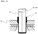
- the prismatic hollow case having the sealed bottom portion is generally manufactured by processing an aluminum alloy plate according to a deep drawing method as exemplified in FIG.1 .
- Deep drawing is a representative forming process of manufacturing a hollow container without a joint using a flat plate in which a plate to be processed 10 disposed on a surface of a die 30 is moved between a punch 20 and die 30 while being compressed in the circumferential direction, resulting in a side wall.
- the deep drawing method Since a plate may be manufactured into a final hollow case through continuous deep drawing processes, the deep drawing method has high efficiency. However, the deep drawing method has some drawbacks as follows.
- materials able to be processed according to the deep drawing method are extremely limited. During the deep drawing process, materials are stretched and, as such, only materials capable of undergoing stretching can be user. However, it is generally difficult to stretch materials having high intensity and, as such, it may be difficult to obtain battery cases having desired characteristics.
- the present invention aims to address the aforementioned problems of the related art and to achieve technical goals that have long been sought.
- the present invention aims to provide a method of manufacturing a prismatic battery cell, production cost of which is reduced due to a simplified manufacturing process and improved production process efficiency, by constituting a battery case such that a prismatic body having an open upper portion and bottom portion by bending and then welding a metal plate having a predetermined thickness, and an upper and bottom portion sealing member corresponding to shape of each of the upper portion and bottom portion of the prismatic body are combined.
- the present invention also aims to provide a method of easily manufacturing a prismatic battery cell while improving a production ratio and obtaining high yield.
- a method of manufacturing a battery cell including an electrode assembly which includes a separator interposed between a cathode and an anode, and is sealed inside a prismatic battery case, the method including:
- a manufacturing cost of the method of manufacturing the battery cell according to the present invention may be reduced by combining together segmented case members, when compared to a deep drawing method.
- the total manufacturing period of the battery cell may be greatly shortened.
- the battery cell may be manufactured in a variety of designs and, at the same time, the error rates of products may be reduced.
- overlapped both end portions of the metal plate bent according to step (a) may be welded in a state that sections of the end portions contact.
- the bent metal plate is welded in a state that the overlapped both end portions are overlapped to a predetermined width.
- a width by which both end portions overlap may be in a range of 0.1 to 10 mm.
- the overlapped portion may be welded after rolling such that the thickness of the overlapped portion is 110% to 150% based on the thickness of the metal plate.
- Such a method of welding a case member is not limited specifically so long as the case member may be combined with high intensity and sealed.
- the welding method may be a laser welding method, arc welding method, electric resistance welding method, gas welding method, ultrasonic welding method, or the like.
- the laser welding method may be more preferable.
- Materials of a metal plate and sealing member constituting the prismatic battery cell according to the present invention are not specifically limited so long as the materials have properties suitable for a battery case, may be manufactured to a plate type and may be used in a manufacturing process of a cell case.
- the materials may be, concretely, aluminum or an aluminum alloy.
- the battery case has a predetermined thickness.
- the battery case may have a thickness of 0.1 to 1 mm.
- the battery case may have a thickness of 0.1 to 1 mm.
- the battery case may not have desired mechanical intensity and the prismatic battery cell may not be protected against external shock. Therefore, the battery case having thickness outside the above range is not preferable.
- the upper portion sealing member and bottom portion sealing member may be manufactured, for example, by a forging, blanking or cutting process.
- the upper portion sealing member may include an electrolyte injection port for electrolyte injection.
- lithium secondary batteries go through a formation process during manufacture of the lithium secondary battery.
- the formation process is a process of charging and discharging the lithium secondary batteries after assembly of the lithium secondary batteries to activate the lithium secondary batteries.
- lithium ions discharged from a cathode of the lithium secondary battery migrate to a carbon electrode, which is used as an anode of the lithium secondary batteries.
- a solid electrolyte interface (SEI) film is formed at the surface of the anode.
- SEI solid electrolyte interface
- the lithium secondary batteries are repeatedly charged and discharged with constant current or constant voltage in a predetermined range.
- at least a portion of outer surfaces of the battery case is coated with an insulative material.
- the insulative material is not specifically restricted so long as the insulative material is coated on the outer surface of the prismatic can to insulate the outer surface of the prismatic can from the outside.
- the coating of the prismatic can with the insulative material may be achieved by anodizing an aluminum oxide on the outer surface of the prismatic can, by spraying the insulative material to the outer surface of the prismatic can, or by spreading an insulative thin film label to the outer surface of the prismatic can.
- the electrode assembly which is not particularly limited, is preferably a folding type electrode assembly, stack type electrode assembly and stack/folding type electrode assembly.
- taps extended from an electrode assembly are combined with one electrode lead. Due to the electrode lead, a planar type electrode terminal is formed.
- Korean Patent Application Pub. Nos. 2001-0082058 , 2001-0082059 and 2001-0082060 particularly disclose with respect to the stack/folding type electrode assembly.
- the applications are combined as references of the present invention.
- the battery pack according to the present invention may be applied to a lithium ion secondary battery in which an electrode assembly is impregnated with a lithium-containing electrolyte, a lithium ion polymer battery in which an electrode assembly is impregnated with a gel-type lithium-containing electrolyte, and the like
- a lithium secondary battery includes a cathode, an anode, a separator, and a lithium salt-containing non-aqueous electrolyte.
- the cathode may be manufactured by, for example, coating a mixture of a cathode active material, a conductive agent, and a binder on a cathode current collector and drying the coated cathode current collector.
- the mixture may further include a filler as desired.
- the conductive material is typically added in an amount of 1 to 30 wt% based on a total weight of a mixture including a cathode active material.
- the conductive material there is no particular limit as to the conductive material, so long as it does not cause chemical changes in the fabricated battery and has conductivity.
- Examples of conductive materials include, but are not limited to, graphite such as natural or artificial graphite; carbon black such as carbon black, acetylene black, Ketjen black, channel black, furnace black, lamp black, and thermal black; conductive fibers such as carbon fibers and metallic fibers; metallic powders such as carbon fluoride powder, aluminum powder, and nickel powder; conductive whiskers such as zinc oxide and potassium titanate; conductive metal oxides such as titanium oxide; and polyphenylene derivatives.
- the binder is a component assisting in binding between an active material and a conductive material and in binding of the active material to a current collector.
- the binder may be typically added in an amount of 1 to 50 wt% based on a total weight of a mixture including a cathode active material.
- binder examples include, but are not limited to, polyvinylidene fluoride, polyvinyl alcohols, carboxymethylcellulose (CMC), starch, hydroxypropylcellulose, regenerated cellulose, polyvinyl pyrrolidone, tetrafluoroethylene, polyethylene, polypropylene, ethylene-propylene-diene terpolymer (EPDM), sulfonated EPDM, styrene-butadiene rubber, fluorine rubber, and various copolymers.
- CMC carboxymethylcellulose
- EPDM ethylene-propylene-diene terpolymer
- EPDM ethylene-propylene-diene terpolymer
- EPDM ethylene-propylene-diene terpolymer
- sulfonated EPDM styrene-butadiene rubber
- fluorine rubber fluorine rubber
- the filler is optionally used as a component to inhibit cathode expansion.
- the filler is not particularly limited so long as it is a fibrous material that does not cause chemical changes in the fabricated secondary battery.
- Examples of the filler include olefin-based polymers such as polyethylene and polypropylene; and fibrous materials such as glass fiber and carbon fiber.
- the anode is manufactured by coating and drying an anode active material on an anode current collector.
- the ingredients described above may be further selectively included.
- anode active material examples include, for example, carbon such as hard carbon and graphite-based carbon; metal composite oxides such as Li x Fe 2 O 3 where 0 ⁇ x ⁇ 1, Li x WO 2 where 0 ⁇ x ⁇ 1, Sn x Me 1-x Me'yO z where Me: Mn, Fe, Pb, or Ge; Me': Al, B, P, Si, Group I, II and III elements, or halogens; 0 ⁇ x ⁇ 1; 1 ⁇ y ⁇ 3; and 1 ⁇ z ⁇ 8; lithium metals; lithium alloys; silicon-based alloys; tin-based alloys; metal oxides such as SnO, SnO 2 , PbO, PbO 2 , Pub 2 O3, Pb 3 O 4 , Sb 2 O 3 , Sb 2 O 4 , Sb 2 O 5 , GeO, GeO 2 , Bi 2 O 3 , Bi 2 O 4 , and Bi 2 O 5 ; conductive polymers such as polyacetylene; and Li-Co-N
- the separator is disposed between the cathode and the anode and, as the separator, a thin insulating film with high ion permeability and high mechanical strength is used.
- the separator generally has a pore diameter of 0.01 to 10 ⁇ m and a thickness of 5 to 300 ⁇ m.
- the separator for example, sheets or non-woven fabrics, made of an olefin polymer such as polypropylene; or glass fibers or polyethylene, which have chemical resistance and hydrophobicity, are used.
- a solid electrolyte such as a polymer or the like is used as an electrolyte
- the solid electrolyte may also serve as a separator.
- the lithium salt-containing non-aqueous electrolyte consists of a polar organic electrolyte and a lithium salt.
- the electrolyte may be a non-aqueous liquid electrolyte, an organic solid electrolyte, an inorganic solid electrolyte, or the like.
- non-aqueous liquid electrolyte examples include non-protic organic solvents such as N-methyl-2-pyrollidinone, propylene carbonate, ethylene carbonate, butylene carbonate, dimethyl carbonate, diethyl carbonate, gamma-butyrolactone, 1,2-dimethoxy ethane, tetrahydrofuran, 2-methyl tetrahydrofuran, dimethylsulfoxide, 1,3-dioxolane, formamide, dimethylformamide, dioxolane, acetonitrile, nitromethane, methyl formate, methyl acetate, phosphoric acid triester, trimethoxy methane, dioxolane derivatives, sulfolane, methyl sulfolane, 1,3-dimethyl-2-imidazolidinone, propylene carbonate derivatives, tetrahydrofuran derivatives, ether, methyl propionate, and ethyl propionate.
- organic solid electrolyte examples include polyethylene derivatives, polyethylene oxide derivatives, polypropylene oxide derivatives, phosphoric acid ester polymers, poly agitation lysine, polyester sulfide, polyvinyl alcohols, polyvinylidene fluoride, and polymers containing ionic dissociation groups.
- Examples of the inorganic solid electrolyte include, without being limited to, nitrides, halides and sulfates of lithium (Li) such as Li 3 N, LiI, Li 5 NI 2 , Li 3 N-LiI-LiOH, LiSiO 4 , LiSiO 4 -LiI-LiOH, Li 2 SiS 3 , Li 4 SiO 4 , Li 4 SiO 4 -LiI-LiOH, and Li 3 PO 4 -Li 2 S-SiS 2 .
- Li lithium
- the lithium salt is a material that is readily soluble in the non-aqueous electrolyte and examples thereof include, without being limited to, LiCl, LiBr, LiI, LiClO 4 , LiBF 4 , LiB 10 Cl 10 , LiPF 6 , LiCF 3 SO 3 , LiCF 3 CO 2 , LiAsF 6 , LiSbF 6 , LiAlCl 4 , CH 3 SO 3 Li, CF 3 SO 3 Li, (CF 3 SO 2 ) 2 NLi, chloroborane lithium, lower aliphatic carboxylic acid lithium, lithium tetraphenyl borate, and imides.
- pyridine triethylphosphite, triethanolamine, cyclic ether, ethylenediamine, n-glyme, hexaphosphoric triamide, nitrobenzene derivatives, sulfur, quinone imine dyes, N-substituted oxazolidinone, N,N-substituted imidazolidine, ethylene glycol dialkyl ether, ammonium salts, pyrrole, 2-methoxy ethanol, aluminum trichloride or the like may be added to the non-aqueous electrolyte.
- the non-aqueous electrolyte may further include halogen-containing solvents such as carbon tetrachloride and ethylene trifluoride. Further, in order to improve high-temperature storage characteristics, the non-aqueous electrolyte may further include carbon dioxide gas.
- the present invention also provides a battery cell manufactured according to the above method.
- the present invention provides a battery pack including at least one prismatic battery cell and a device using the battery pack as a power supply.
- the device may be, concretely, laptop computers, cellular phones, PDPs, PMPs, MP3 players, digital still cameras (DSCs), DVRs, smart phones, GPS systems, camcorders, electric vehicles, hybrid electric vehicles, and plug-in hybrid electric vehicles, power storage devices, and the like.
- a battery case is constituted such that an upper and bottom portion sealing member corresponding to the shape of each of an upper portion and bottom portion of a prismatic body, which has an upper and bottom portion which are open by bending and then welding a metal plate of a predetermined thickness, are combined each other. Consequently, a manufacturing method of the prismatic battery cell is simplified and production process efficiency is improved and, accordingly, manufacturing costs are reduced and a prismatic battery cell which was not manufactured using a deep drawing method may be manufactured.
- FIG. 2 illustrates an exploded perspective view of a prismatic battery cell according to one example of the present invention.
- the prismatic battery cell 100 includes an electrode assembly 110 including a separator interposed between a cathode and an anode embedded in a prismatic battery case.
- a prismatic body 120 having an upper portion and bottom portion which are opened by bending and then welding a metal plate having a predetermined thickness, an upper portion sealing member 130 and bottom portion sealing member 140 corresponding to the shape of each of the upper portion and bottom portion of the prismatic body 120 are respectively manufactured. After inserting the electrode assembly 110 into the battery case, the upper portion sealing member 130 and the bottom portion sealing member 140 contact with the prismatic body 120 and then are welded, resulting in completion of fabrication of a prismatic battery cell 100.
- the prismatic battery cell 100 having such a structure includes a welding side 150 in which end portions of a metal plate at one side of the prismatic battery cell 100 are welded since the prismatic body 120 constituting the prismatic battery cell 100 is manufactured by bending and then welding a metal plate.
- FIG. 3 is a schematic view illustrating a method of manufacturing the prismatic body according to a comparative example.
- FIG. 4 is a schematic view illustrating a method of manufacturing the prismatic body according to the present invention.
- a metal plate 210 which is made of aluminum alloy and has a thickness of, approximately, 0.3 mm, is bent in the shape of the battery case as illustrated in FIG. 3 .
- the bent metal plate 210 contacts with overlapped both end portions 220 and 230 and, at this time, is combined with the both end portions 220 and 230 by laser welding, resulting in a prismatic body 200 having an upper portion and bottom portion which are open.
- both end portions 320 and 330 facing a bent metal plate 310 may be combined by laser welding such that the end portions 320 and 330 are overlapped by, approximately, 0.4 mm, resulting in a prismatic body 300 having an upper portion and bottom portion which are open.
- the end portions 320 and 330 of the metal plate 310 are rolled and welded such that the thickness of the end portions 320 and 330 is 110 to 150% based on the thickness of the metal plate 310.
- the battery cell according to the present invention is manufactured by combining each case member which is segmented and thereby manufacturing costs may be reduced, total manufacturing periods of the battery cell may be greatly shortened, the battery cell may be manufactured in a variety of designs and, at the same time, error rates of products may be reduced.
Landscapes
- Chemical & Material Sciences (AREA)
- Chemical Kinetics & Catalysis (AREA)
- Electrochemistry (AREA)
- General Chemical & Material Sciences (AREA)
- Engineering & Computer Science (AREA)
- Physics & Mathematics (AREA)
- Optics & Photonics (AREA)
- Manufacturing & Machinery (AREA)
- Plasma & Fusion (AREA)
- Mechanical Engineering (AREA)
- Materials Engineering (AREA)
- Metallurgy (AREA)
- Organic Chemistry (AREA)
- Sealing Battery Cases Or Jackets (AREA)
- Secondary Cells (AREA)
- Filling, Topping-Up Batteries (AREA)
- Battery Mounting, Suspending (AREA)
Claims (13)
- Verfahren zum Herstellen einer Batteriezelle (100), welche innerhalb eines prismatischen Batteriegehäuses abgedichtet ist, umfassend eine Elektrodenanordnung (110), umfassend eine Katode, eine Anode und einen Separator, welcher zwischen der Katode und der Anode angeordnet ist, wobei das Verfahren umfasst:Biegen und dann Verschweißen einer Metallplatte (310) mit einer vorbestimmten Dicke, um einen prismatischen Körper (300) mit einem offenen oberen Abschnitt und unteren Abschnitt herzustellen;Herstellen von Dichtungselementen für den oberen und unteren Abschnitt (130, 140), welche der Form von jedem aus einem oberen Abschnitt und einem unteren Abschnitt eines prismatischen Körpers (300) entsprechen;Kontaktieren und dann Verschweißen des Dichtungselements für den unteren Abschnitt (140) mit dem unteren Abschnitt des prismatischen Körpers (300);Einsetzen der Elektrodenanordnung (110) in das Batteriegehäuse mit einem abgedichteten unteren Abschnitt, welcher gemäß dem Kontaktieren und dann Verschweißen hergestellt ist; undKontaktieren und dann Verschweißen des Dichtungselements für den oberen Abschnitt (130) mit dem oberen Abschnitt des Batteriegehäuses, welcher gemäß dem Einsetzen hergestellt ist,dadurch gekennzeichnet, dassüberlappende beide Endabschnitte (320, 330) der Metallplatte (310), welche gemäß dem Biegen gebogen sind, in einem Zustand verschweißt sind, in welchem die überlappenden beiden Endabschnitte (320, 330) bis zu einer vorbestimmten Breite überlappend sind.
- Verfahren nach Anspruch 1, wobei die Elektrodenanordnung (110) eine Elektrodenanordnung vom Falttyp (110), eine Elektrodenanordnung vom Stapeltyp (110) oder eine Elektrodenanordnung vom Stapel-/Falttyp (110) ist.
- Verfahren nach Anspruch 1, wobei die beiden Endabschnitte (320, 330) in einem Bereich einer Breite von 0,1 bis 10 mm überlappend sind.
- Verfahren nach Anspruch 1, wobei eine Dicke eines überlappenden Bereichs der beiden Endabschnitte (320, 330) basierend auf einer Dicke einer Metallplatte (310) 110% bis 150% beträgt.
- Verfahren nach Anspruch 1, wobei das Verschweißen durch ein Laserschweißverfahren durchgeführt wird.
- Verfahren Anspruch 1, wobei das Dichtungselement für den oberen Abschnitt (130) eine Elektrolyt-Injektionsöffnung für eine Elektrolyt-Injektion umfasst.
- Verfahren nach Anspruch 1, wobei jedes aus der Metallplatte (310) und den Dichtungselementen aus Aluminium oder einer Aluminiumlegierung hergestellt ist.
- Verfahren nach Anspruch 1, wobei die Metallplatte (310) und die Dichtungselemente eine Dicke von 0,1 bis 1 mm aufweisen.
- Verfahren nach Anspruch 1, wobei das Dichtungselement für den oberen Abschnitt (130) und das Dichtungselement für den unteren Abschnitt (140) durch ein Schmiedeverfahren, ein Stanzverfahren oder ein Schneidverfahren hergestellt sind.
- Verfahren nach Anspruch 1, wobei wenigstens ein Abschnitt von äußeren Seiten des prismatischen Batteriegehäuses mit einem isolierenden Material beschichtet wird.
- Verfahren nach Anspruch 10, wobei das Beschichten durch Anodisieren von Aluminiumoxid durchgeführt wird.
- Verfahren nach Anspruch 10, wobei das Beschichten durch Aufsprühen eines isolierenden Materials durchgeführt wird.
- Verfahren nach Anspruch 10, wobei das Beschichten durch Verteilen eines isolierenden Dünnfilmauftrags durchgeführt wird.
Applications Claiming Priority (2)
| Application Number | Priority Date | Filing Date | Title |
|---|---|---|---|
| KR1020130106641A KR101563578B1 (ko) | 2013-09-05 | 2013-09-05 | 금속 판재를 사용한 각형 전지셀의 제조방법 |
| PCT/KR2014/006379 WO2015034173A1 (ko) | 2013-09-05 | 2014-07-15 | 금속 판재를 사용한 각형 전지셀의 제조방법 |
Publications (3)
| Publication Number | Publication Date |
|---|---|
| EP3024084A1 EP3024084A1 (de) | 2016-05-25 |
| EP3024084A4 EP3024084A4 (de) | 2016-09-14 |
| EP3024084B1 true EP3024084B1 (de) | 2018-01-03 |
Family
ID=52628598
Family Applications (1)
| Application Number | Title | Priority Date | Filing Date |
|---|---|---|---|
| EP14842727.1A Active EP3024084B1 (de) | 2013-09-05 | 2014-07-15 | Verfahren zur herstellung einer rechteckigen batteriezelle mit metallplatten |
Country Status (7)
| Country | Link |
|---|---|
| US (1) | US20160204392A1 (de) |
| EP (1) | EP3024084B1 (de) |
| JP (1) | JP6220071B2 (de) |
| KR (1) | KR101563578B1 (de) |
| CN (1) | CN105474453A (de) |
| TW (1) | TWI525877B (de) |
| WO (1) | WO2015034173A1 (de) |
Families Citing this family (14)
| Publication number | Priority date | Publication date | Assignee | Title |
|---|---|---|---|---|
| US10340483B2 (en) | 2014-08-26 | 2019-07-02 | Cps Technology Holdings Llc | Welding process for sealing a battery module |
| JP6536885B2 (ja) | 2015-06-15 | 2019-07-03 | トヨタ自動車株式会社 | 電池容器の製造方法および電池容器 |
| KR102139065B1 (ko) * | 2017-02-13 | 2020-07-29 | 주식회사 엘지화학 | 무기물 코팅부를 포함하고 있는 원통형 전지셀 |
| CN110983412B (zh) * | 2019-03-26 | 2022-03-29 | 国研新能(深圳)技术有限公司 | 一种基于原位生成法制备硬质氧化铝膜在铝壳锂电池绝缘密封中的应用 |
| SG11202110988XA (en) | 2019-04-01 | 2021-10-28 | Spear Power Systems Inc | Apparatus for mitigation of thermal event propagation for battery systems |
| KR102793401B1 (ko) * | 2019-06-10 | 2025-04-09 | 삼성에스디아이 주식회사 | 이차 전지 |
| CN111129574A (zh) * | 2019-12-12 | 2020-05-08 | 深圳市东方芯愿新能源有限公司 | 一种一体成型的充电式电池及生产方法 |
| KR20210145489A (ko) * | 2020-05-25 | 2021-12-02 | 삼성에스디아이 주식회사 | 이차전지 |
| KR102472909B1 (ko) * | 2020-10-12 | 2022-12-01 | 삼성에스디아이 주식회사 | 배터리 팩 |
| DE102021111440A1 (de) | 2021-05-04 | 2022-11-10 | Audi Aktiengesellschaft | Verfahren zum Bereitstellen eines Zellgehäuseteils, Zellgehäuseteil und Batteriezelle für eine Hochvoltbatterie eines Kraftfahrzeugs |
| CN215496865U (zh) * | 2021-05-26 | 2022-01-11 | 惠州亿纬锂能股份有限公司 | 电池外壳和锂电池 |
| KR102944814B1 (ko) * | 2022-01-05 | 2026-03-27 | 삼성에스디아이 주식회사 | 이차전지 |
| JP7834072B2 (ja) * | 2023-09-27 | 2026-03-23 | プライムプラネットエナジー&ソリューションズ株式会社 | 二次電池用ケースの製造方法、二次電池の製造方法および二次電池 |
| CN117691264B (zh) * | 2024-02-04 | 2024-04-19 | 蜂巢能源科技股份有限公司 | 电池壳体、电池外壳及电池 |
Family Cites Families (29)
| Publication number | Priority date | Publication date | Assignee | Title |
|---|---|---|---|---|
| KR100515571B1 (ko) | 2000-02-08 | 2005-09-20 | 주식회사 엘지화학 | 중첩 전기 화학 셀 |
| KR100497147B1 (ko) | 2000-02-08 | 2005-06-29 | 주식회사 엘지화학 | 다중 중첩 전기화학 셀 및 그의 제조방법 |
| KR100515572B1 (ko) | 2000-02-08 | 2005-09-20 | 주식회사 엘지화학 | 중첩 전기화학 셀 및 그의 제조 방법 |
| JP2001236929A (ja) * | 2000-02-22 | 2001-08-31 | Sumitomo Metal Ind Ltd | チタン製電池ケース |
| JP4316470B2 (ja) * | 2003-10-31 | 2009-08-19 | 株式会社三五 | レーザ溶接による容器の製造方法 |
| KR100614367B1 (ko) * | 2004-10-28 | 2006-08-21 | 삼성에스디아이 주식회사 | 이차 전지 |
| KR100648731B1 (ko) * | 2005-03-21 | 2006-11-23 | 삼성에스디아이 주식회사 | 이차전지 및 이의 제조 방법 |
| KR20060118955A (ko) * | 2005-05-18 | 2006-11-24 | 삼성에스디아이 주식회사 | 권취형 전극 조립체 및 이를 구비하는 리튬 이차 전지 |
| KR101082870B1 (ko) * | 2006-12-23 | 2011-11-11 | 주식회사 엘지화학 | 금속 소재의 전지팩 케이스 |
| JP4495751B2 (ja) * | 2007-07-24 | 2010-07-07 | 太陽誘電株式会社 | 電気化学デバイスの製造方法 |
| JP2010074113A (ja) * | 2008-09-16 | 2010-04-02 | Jcc Engineering Co Ltd | 電子部品の製造方法及び装置 |
| KR101002511B1 (ko) * | 2008-09-19 | 2010-12-17 | 삼성에스디아이 주식회사 | 폴리머 전지팩 |
| JP5490406B2 (ja) * | 2008-12-27 | 2014-05-14 | 三洋電機株式会社 | 車両用の電源装置 |
| JP5354755B2 (ja) * | 2010-03-08 | 2013-11-27 | 日立マクセル株式会社 | リチウムイオン二次電池 |
| KR101135498B1 (ko) * | 2010-06-03 | 2012-04-13 | 삼성에스디아이 주식회사 | 이차 전지 및 그 캔 |
| JP5589737B2 (ja) * | 2010-10-07 | 2014-09-17 | トヨタ自動車株式会社 | 電池及びその製造方法 |
| KR101182274B1 (ko) * | 2010-10-13 | 2012-09-13 | 삼성에스디아이 주식회사 | 이차 전지 및 그 제조방법 |
| JP5662776B2 (ja) * | 2010-12-03 | 2015-02-04 | Udトラックス株式会社 | 蓄電セル |
| US8748034B2 (en) * | 2011-04-14 | 2014-06-10 | Gs Yuasa International Ltd. | Battery including baffling member including one of projecting portion and recessed portion extending from lid plate |
| JP6142466B2 (ja) * | 2011-05-25 | 2017-06-07 | 株式会社Gsユアサ | 電池の製造方法、および、電池 |
| DE102011079289A1 (de) * | 2011-07-18 | 2013-01-24 | Sb Limotive Company Ltd. | Verfahren zur Herstellung einer Batterie mit einem metallischen Gehäuse und einer die Außenseite des Gehäuses bedeckenden elektrischen Isolationsschicht sowie nach dem Verfahren hergestellte Batterie |
| US9324977B2 (en) * | 2011-10-12 | 2016-04-26 | Samsung Sdi Co., Ltd. | Secondary battery |
| JP5821605B2 (ja) * | 2011-12-16 | 2015-11-24 | 三菱自動車工業株式会社 | 二次電池 |
| KR101504219B1 (ko) * | 2012-01-04 | 2015-03-19 | 주식회사 엘지화학 | 이차전지용 케이스 및 이를 이용한 전극 조립체의 케이싱 방법 |
| JP5869354B2 (ja) * | 2012-02-01 | 2016-02-24 | 日立マクセル株式会社 | 角形リチウムイオン二次電池用外装缶および角形リチウムイオン二次電池 |
| KR101422656B1 (ko) * | 2012-02-07 | 2014-07-23 | 주식회사 엘지화학 | 신규한 구조의 내장형 전지셀 |
| JP6179285B2 (ja) * | 2012-10-12 | 2017-08-16 | 株式会社Gsユアサ | 蓄電素子、被覆シート及び容器の被覆方法 |
| CN104078631B (zh) * | 2013-03-27 | 2019-03-08 | 株式会社杰士汤浅国际 | 蓄电元件及蓄电装置 |
| KR20140121205A (ko) * | 2013-04-05 | 2014-10-15 | 삼성에스디아이 주식회사 | 이차 전지 및 이의 외면을 절연시키는 방법 |
-
2013
- 2013-09-05 KR KR1020130106641A patent/KR101563578B1/ko active Active
-
2014
- 2014-07-15 US US14/913,313 patent/US20160204392A1/en not_active Abandoned
- 2014-07-15 WO PCT/KR2014/006379 patent/WO2015034173A1/ko not_active Ceased
- 2014-07-15 JP JP2016536017A patent/JP6220071B2/ja active Active
- 2014-07-15 CN CN201480046062.4A patent/CN105474453A/zh active Pending
- 2014-07-15 EP EP14842727.1A patent/EP3024084B1/de active Active
- 2014-07-22 TW TW103125103A patent/TWI525877B/zh active
Also Published As
| Publication number | Publication date |
|---|---|
| JP6220071B2 (ja) | 2017-10-25 |
| KR101563578B1 (ko) | 2015-10-27 |
| EP3024084A4 (de) | 2016-09-14 |
| JP2016531403A (ja) | 2016-10-06 |
| KR20150028040A (ko) | 2015-03-13 |
| TWI525877B (zh) | 2016-03-11 |
| WO2015034173A1 (ko) | 2015-03-12 |
| TW201526350A (zh) | 2015-07-01 |
| CN105474453A (zh) | 2016-04-06 |
| EP3024084A1 (de) | 2016-05-25 |
| US20160204392A1 (en) | 2016-07-14 |
Similar Documents
| Publication | Publication Date | Title |
|---|---|---|
| EP3024084B1 (de) | Verfahren zur herstellung einer rechteckigen batteriezelle mit metallplatten | |
| EP3035432B1 (de) | Batteriezellenbiegungsvorrichtung mit einem heizelement | |
| KR102018849B1 (ko) | 돌출 연장부와 탭 연결부를 구비한 전극 리드를 포함하고 있는 전지셀 | |
| KR101933655B1 (ko) | 전극 탭 부위에 형성된 만입부를 포함하는 전지셀 | |
| EP2922135B1 (de) | Batteriezelle mit amorpher struktur | |
| EP2958178B1 (de) | Elektrodenanordnung mit geneigter struktur und batteriezelle damit | |
| EP3654415B1 (de) | Elektrode ohne stromkollektor und sekundärbatterie damit | |
| KR101879911B1 (ko) | 휘어진 형상의 전지셀 제조방법 | |
| KR20100082704A (ko) | 안전성이 향상된 파우치형 이차전지 | |
| KR102082467B1 (ko) | 집전체 중심 부위에 높은 활물질 로딩량을 가지는 전극을 포함하는 전극조립체 | |
| KR20160074209A (ko) | 각형 만곡 이차전지 및 이의 제조방법 | |
| KR101811837B1 (ko) | 잉여 실링부를 포함하는 파우치형 전지셀 | |
| KR101671386B1 (ko) | 보호용 케이스를 이용한 이차전지 제조방법 | |
| KR101554141B1 (ko) | 판상형 전지셀 | |
| KR101307772B1 (ko) | 이차전지 제조방법 및 이를 이용하여 생산되는 이차전지 | |
| KR102201632B1 (ko) | 상부 케이스와 하부 케이스의 수납부 크기가 상이한 전지셀 | |
| KR101791432B1 (ko) | 집전체의 일부로 이루어진 전극단자를 포함하는 전극조립체 | |
| KR101661254B1 (ko) | 하이브리드 스택-폴딩형 전극조립체 및 이를 포함하는 이차전지 | |
| KR101666413B1 (ko) | 하이브리드 스택-폴딩형 전극조립체 및 이를 포함하는 이차전지 | |
| KR101645463B1 (ko) | 하이브리드 스택-폴딩형 전극조립체 및 이를 포함하는 이차전지 | |
| KR20160096468A (ko) | 단차를 갖는 젤리-롤형 전극조립체를 포함하는 이차전지 | |
| KR20160047737A (ko) | 전지셀 제조용 지그 및 이를 사용하여 제조되는 전지셀 | |
| KR101666415B1 (ko) | 하이브리드 스택-폴딩형 전극조립체 및 이를 포함하는 이차전지 | |
| KR20140006722A (ko) | 이차전지의 제조방법 및 이에 따른 이차전지, 전기화학소자 | |
| KR20130093875A (ko) | 낮은 저항과 우수한 제조 공정성의 전극 탭을 포함하는 이차전지 |
Legal Events
| Date | Code | Title | Description |
|---|---|---|---|
| PUAI | Public reference made under article 153(3) epc to a published international application that has entered the european phase |
Free format text: ORIGINAL CODE: 0009012 |
|
| 17P | Request for examination filed |
Effective date: 20160216 |
|
| AK | Designated contracting states |
Kind code of ref document: A1 Designated state(s): AL AT BE BG CH CY CZ DE DK EE ES FI FR GB GR HR HU IE IS IT LI LT LU LV MC MK MT NL NO PL PT RO RS SE SI SK SM TR |
|
| AX | Request for extension of the european patent |
Extension state: BA ME |
|
| A4 | Supplementary search report drawn up and despatched |
Effective date: 20160817 |
|
| RIC1 | Information provided on ipc code assigned before grant |
Ipc: H01M 10/04 20060101ALI20160810BHEP Ipc: H01M 10/052 20100101ALN20160810BHEP Ipc: H01M 2/02 20060101AFI20160810BHEP |
|
| DAX | Request for extension of the european patent (deleted) | ||
| REG | Reference to a national code |
Ref country code: DE Ref legal event code: R079 Ref document number: 602014019556 Country of ref document: DE Free format text: PREVIOUS MAIN CLASS: H01M0010058000 Ipc: H01M0002020000 |
|
| RIC1 | Information provided on ipc code assigned before grant |
Ipc: H01M 10/04 20060101ALI20170413BHEP Ipc: H01M 2/02 20060101AFI20170413BHEP Ipc: H01M 10/052 20100101ALN20170413BHEP |
|
| GRAP | Despatch of communication of intention to grant a patent |
Free format text: ORIGINAL CODE: EPIDOSNIGR1 |
|
| STAA | Information on the status of an ep patent application or granted ep patent |
Free format text: STATUS: GRANT OF PATENT IS INTENDED |
|
| INTG | Intention to grant announced |
Effective date: 20171020 |
|
| GRAS | Grant fee paid |
Free format text: ORIGINAL CODE: EPIDOSNIGR3 |
|
| GRAA | (expected) grant |
Free format text: ORIGINAL CODE: 0009210 |
|
| STAA | Information on the status of an ep patent application or granted ep patent |
Free format text: STATUS: THE PATENT HAS BEEN GRANTED |
|
| AK | Designated contracting states |
Kind code of ref document: B1 Designated state(s): AL AT BE BG CH CY CZ DE DK EE ES FI FR GB GR HR HU IE IS IT LI LT LU LV MC MK MT NL NO PL PT RO RS SE SI SK SM TR |
|
| REG | Reference to a national code |
Ref country code: GB Ref legal event code: FG4D |
|
| REG | Reference to a national code |
Ref country code: CH Ref legal event code: EP Ref country code: AT Ref legal event code: REF Ref document number: 961048 Country of ref document: AT Kind code of ref document: T Effective date: 20180115 |
|
| REG | Reference to a national code |
Ref country code: IE Ref legal event code: FG4D |
|
| REG | Reference to a national code |
Ref country code: DE Ref legal event code: R096 Ref document number: 602014019556 Country of ref document: DE |
|
| REG | Reference to a national code |
Ref country code: NL Ref legal event code: MP Effective date: 20180103 |
|
| REG | Reference to a national code |
Ref country code: LT Ref legal event code: MG4D |
|
| REG | Reference to a national code |
Ref country code: AT Ref legal event code: MK05 Ref document number: 961048 Country of ref document: AT Kind code of ref document: T Effective date: 20180103 |
|
| REG | Reference to a national code |
Ref country code: FR Ref legal event code: PLFP Year of fee payment: 5 |
|
| PG25 | Lapsed in a contracting state [announced via postgrant information from national office to epo] |
Ref country code: NL Free format text: LAPSE BECAUSE OF FAILURE TO SUBMIT A TRANSLATION OF THE DESCRIPTION OR TO PAY THE FEE WITHIN THE PRESCRIBED TIME-LIMIT Effective date: 20180103 |
|
| PG25 | Lapsed in a contracting state [announced via postgrant information from national office to epo] |
Ref country code: FI Free format text: LAPSE BECAUSE OF FAILURE TO SUBMIT A TRANSLATION OF THE DESCRIPTION OR TO PAY THE FEE WITHIN THE PRESCRIBED TIME-LIMIT Effective date: 20180103 Ref country code: CY Free format text: LAPSE BECAUSE OF FAILURE TO SUBMIT A TRANSLATION OF THE DESCRIPTION OR TO PAY THE FEE WITHIN THE PRESCRIBED TIME-LIMIT Effective date: 20180103 Ref country code: NO Free format text: LAPSE BECAUSE OF FAILURE TO SUBMIT A TRANSLATION OF THE DESCRIPTION OR TO PAY THE FEE WITHIN THE PRESCRIBED TIME-LIMIT Effective date: 20180403 Ref country code: HR Free format text: LAPSE BECAUSE OF FAILURE TO SUBMIT A TRANSLATION OF THE DESCRIPTION OR TO PAY THE FEE WITHIN THE PRESCRIBED TIME-LIMIT Effective date: 20180103 Ref country code: LT Free format text: LAPSE BECAUSE OF FAILURE TO SUBMIT A TRANSLATION OF THE DESCRIPTION OR TO PAY THE FEE WITHIN THE PRESCRIBED TIME-LIMIT Effective date: 20180103 Ref country code: ES Free format text: LAPSE BECAUSE OF FAILURE TO SUBMIT A TRANSLATION OF THE DESCRIPTION OR TO PAY THE FEE WITHIN THE PRESCRIBED TIME-LIMIT Effective date: 20180103 |
|
| PG25 | Lapsed in a contracting state [announced via postgrant information from national office to epo] |
Ref country code: PL Free format text: LAPSE BECAUSE OF FAILURE TO SUBMIT A TRANSLATION OF THE DESCRIPTION OR TO PAY THE FEE WITHIN THE PRESCRIBED TIME-LIMIT Effective date: 20180103 Ref country code: LV Free format text: LAPSE BECAUSE OF FAILURE TO SUBMIT A TRANSLATION OF THE DESCRIPTION OR TO PAY THE FEE WITHIN THE PRESCRIBED TIME-LIMIT Effective date: 20180103 Ref country code: SE Free format text: LAPSE BECAUSE OF FAILURE TO SUBMIT A TRANSLATION OF THE DESCRIPTION OR TO PAY THE FEE WITHIN THE PRESCRIBED TIME-LIMIT Effective date: 20180103 Ref country code: GR Free format text: LAPSE BECAUSE OF FAILURE TO SUBMIT A TRANSLATION OF THE DESCRIPTION OR TO PAY THE FEE WITHIN THE PRESCRIBED TIME-LIMIT Effective date: 20180404 Ref country code: IS Free format text: LAPSE BECAUSE OF FAILURE TO SUBMIT A TRANSLATION OF THE DESCRIPTION OR TO PAY THE FEE WITHIN THE PRESCRIBED TIME-LIMIT Effective date: 20180503 Ref country code: BG Free format text: LAPSE BECAUSE OF FAILURE TO SUBMIT A TRANSLATION OF THE DESCRIPTION OR TO PAY THE FEE WITHIN THE PRESCRIBED TIME-LIMIT Effective date: 20180403 Ref country code: AT Free format text: LAPSE BECAUSE OF FAILURE TO SUBMIT A TRANSLATION OF THE DESCRIPTION OR TO PAY THE FEE WITHIN THE PRESCRIBED TIME-LIMIT Effective date: 20180103 Ref country code: RS Free format text: LAPSE BECAUSE OF FAILURE TO SUBMIT A TRANSLATION OF THE DESCRIPTION OR TO PAY THE FEE WITHIN THE PRESCRIBED TIME-LIMIT Effective date: 20180103 |
|
| REG | Reference to a national code |
Ref country code: DE Ref legal event code: R097 Ref document number: 602014019556 Country of ref document: DE |
|
| PG25 | Lapsed in a contracting state [announced via postgrant information from national office to epo] |
Ref country code: AL Free format text: LAPSE BECAUSE OF FAILURE TO SUBMIT A TRANSLATION OF THE DESCRIPTION OR TO PAY THE FEE WITHIN THE PRESCRIBED TIME-LIMIT Effective date: 20180103 Ref country code: IT Free format text: LAPSE BECAUSE OF FAILURE TO SUBMIT A TRANSLATION OF THE DESCRIPTION OR TO PAY THE FEE WITHIN THE PRESCRIBED TIME-LIMIT Effective date: 20180103 Ref country code: EE Free format text: LAPSE BECAUSE OF FAILURE TO SUBMIT A TRANSLATION OF THE DESCRIPTION OR TO PAY THE FEE WITHIN THE PRESCRIBED TIME-LIMIT Effective date: 20180103 Ref country code: RO Free format text: LAPSE BECAUSE OF FAILURE TO SUBMIT A TRANSLATION OF THE DESCRIPTION OR TO PAY THE FEE WITHIN THE PRESCRIBED TIME-LIMIT Effective date: 20180103 |
|
| PLBE | No opposition filed within time limit |
Free format text: ORIGINAL CODE: 0009261 |
|
| STAA | Information on the status of an ep patent application or granted ep patent |
Free format text: STATUS: NO OPPOSITION FILED WITHIN TIME LIMIT |
|
| PG25 | Lapsed in a contracting state [announced via postgrant information from national office to epo] |
Ref country code: CZ Free format text: LAPSE BECAUSE OF FAILURE TO SUBMIT A TRANSLATION OF THE DESCRIPTION OR TO PAY THE FEE WITHIN THE PRESCRIBED TIME-LIMIT Effective date: 20180103 Ref country code: DK Free format text: LAPSE BECAUSE OF FAILURE TO SUBMIT A TRANSLATION OF THE DESCRIPTION OR TO PAY THE FEE WITHIN THE PRESCRIBED TIME-LIMIT Effective date: 20180103 Ref country code: SM Free format text: LAPSE BECAUSE OF FAILURE TO SUBMIT A TRANSLATION OF THE DESCRIPTION OR TO PAY THE FEE WITHIN THE PRESCRIBED TIME-LIMIT Effective date: 20180103 Ref country code: SK Free format text: LAPSE BECAUSE OF FAILURE TO SUBMIT A TRANSLATION OF THE DESCRIPTION OR TO PAY THE FEE WITHIN THE PRESCRIBED TIME-LIMIT Effective date: 20180103 |
|
| 26N | No opposition filed |
Effective date: 20181005 |
|
| PG25 | Lapsed in a contracting state [announced via postgrant information from national office to epo] |
Ref country code: SI Free format text: LAPSE BECAUSE OF FAILURE TO SUBMIT A TRANSLATION OF THE DESCRIPTION OR TO PAY THE FEE WITHIN THE PRESCRIBED TIME-LIMIT Effective date: 20180103 |
|
| REG | Reference to a national code |
Ref country code: CH Ref legal event code: PL |
|
| PG25 | Lapsed in a contracting state [announced via postgrant information from national office to epo] |
Ref country code: MC Free format text: LAPSE BECAUSE OF FAILURE TO SUBMIT A TRANSLATION OF THE DESCRIPTION OR TO PAY THE FEE WITHIN THE PRESCRIBED TIME-LIMIT Effective date: 20180103 Ref country code: LU Free format text: LAPSE BECAUSE OF NON-PAYMENT OF DUE FEES Effective date: 20180715 |
|
| REG | Reference to a national code |
Ref country code: BE Ref legal event code: MM Effective date: 20180731 |
|
| REG | Reference to a national code |
Ref country code: IE Ref legal event code: MM4A |
|
| PG25 | Lapsed in a contracting state [announced via postgrant information from national office to epo] |
Ref country code: LI Free format text: LAPSE BECAUSE OF NON-PAYMENT OF DUE FEES Effective date: 20180731 Ref country code: CH Free format text: LAPSE BECAUSE OF NON-PAYMENT OF DUE FEES Effective date: 20180731 Ref country code: IE Free format text: LAPSE BECAUSE OF NON-PAYMENT OF DUE FEES Effective date: 20180715 |
|
| PG25 | Lapsed in a contracting state [announced via postgrant information from national office to epo] |
Ref country code: BE Free format text: LAPSE BECAUSE OF NON-PAYMENT OF DUE FEES Effective date: 20180731 |
|
| PG25 | Lapsed in a contracting state [announced via postgrant information from national office to epo] |
Ref country code: MT Free format text: LAPSE BECAUSE OF NON-PAYMENT OF DUE FEES Effective date: 20180715 |
|
| PG25 | Lapsed in a contracting state [announced via postgrant information from national office to epo] |
Ref country code: TR Free format text: LAPSE BECAUSE OF FAILURE TO SUBMIT A TRANSLATION OF THE DESCRIPTION OR TO PAY THE FEE WITHIN THE PRESCRIBED TIME-LIMIT Effective date: 20180103 |
|
| PG25 | Lapsed in a contracting state [announced via postgrant information from national office to epo] |
Ref country code: PT Free format text: LAPSE BECAUSE OF FAILURE TO SUBMIT A TRANSLATION OF THE DESCRIPTION OR TO PAY THE FEE WITHIN THE PRESCRIBED TIME-LIMIT Effective date: 20180103 |
|
| PG25 | Lapsed in a contracting state [announced via postgrant information from national office to epo] |
Ref country code: HU Free format text: LAPSE BECAUSE OF FAILURE TO SUBMIT A TRANSLATION OF THE DESCRIPTION OR TO PAY THE FEE WITHIN THE PRESCRIBED TIME-LIMIT; INVALID AB INITIO Effective date: 20140715 Ref country code: MK Free format text: LAPSE BECAUSE OF NON-PAYMENT OF DUE FEES Effective date: 20180103 |
|
| REG | Reference to a national code |
Ref country code: DE Ref legal event code: R079 Ref document number: 602014019556 Country of ref document: DE Free format text: PREVIOUS MAIN CLASS: H01M0002020000 Ipc: H01M0050100000 |
|
| P01 | Opt-out of the competence of the unified patent court (upc) registered |
Effective date: 20230512 |
|
| REG | Reference to a national code |
Ref country code: DE Ref legal event code: R081 Ref document number: 602014019556 Country of ref document: DE Owner name: LG ENERGY SOLUTION, LTD., KR Free format text: FORMER OWNER: LG CHEM. LTD., SEOUL, KR |
|
| REG | Reference to a national code |
Ref country code: GB Ref legal event code: 732E Free format text: REGISTERED BETWEEN 20230824 AND 20230831 |
|
| PGFP | Annual fee paid to national office [announced via postgrant information from national office to epo] |
Ref country code: GB Payment date: 20250624 Year of fee payment: 12 |
|
| PGFP | Annual fee paid to national office [announced via postgrant information from national office to epo] |
Ref country code: FR Payment date: 20250624 Year of fee payment: 12 |
|
| PGFP | Annual fee paid to national office [announced via postgrant information from national office to epo] |
Ref country code: DE Payment date: 20250624 Year of fee payment: 12 |