EP3024123B1 - Actionneur linéaire et dispositif de commande d'oscillation pour une voiture ferroviaire - Google Patents
Actionneur linéaire et dispositif de commande d'oscillation pour une voiture ferroviaire Download PDFInfo
- Publication number
- EP3024123B1 EP3024123B1 EP14825671.2A EP14825671A EP3024123B1 EP 3024123 B1 EP3024123 B1 EP 3024123B1 EP 14825671 A EP14825671 A EP 14825671A EP 3024123 B1 EP3024123 B1 EP 3024123B1
- Authority
- EP
- European Patent Office
- Prior art keywords
- hollow rotor
- linear actuator
- rotation
- linear motion
- end portion
- Prior art date
- Legal status (The legal status is an assumption and is not a legal conclusion. Google has not performed a legal analysis and makes no representation as to the accuracy of the status listed.)
- Active
Links
Images


Classifications
-
- H—ELECTRICITY
- H02—GENERATION; CONVERSION OR DISTRIBUTION OF ELECTRIC POWER
- H02K—DYNAMO-ELECTRIC MACHINES
- H02K7/00—Arrangements for handling mechanical energy structurally associated with dynamo-electric machines, e.g. structural association with mechanical driving motors or auxiliary dynamo-electric machines
-
- B—PERFORMING OPERATIONS; TRANSPORTING
- B61—RAILWAYS
- B61F—RAIL VEHICLE SUSPENSIONS, e.g. UNDERFRAMES, BOGIES OR ARRANGEMENTS OF WHEEL AXLES; RAIL VEHICLES FOR USE ON TRACKS OF DIFFERENT WIDTH; PREVENTING DERAILING OF RAIL VEHICLES; WHEEL GUARDS, OBSTRUCTION REMOVERS OR THE LIKE FOR RAIL VEHICLES
- B61F5/00—Constructional details of bogies; Connections between bogies and vehicle underframes; Arrangements or devices for adjusting or allowing self-adjustment of wheel axles or bogies when rounding curves
- B61F5/02—Arrangements permitting limited transverse relative movements between vehicle underframe or bolster and bogie; Connections between underframes and bogies
- B61F5/22—Guiding of the vehicle underframes with respect to the bogies
- B61F5/24—Means for damping or minimising the canting, skewing, pitching, or plunging movements of the underframes
- B61F5/245—Means for damping or minimising the canting, skewing, pitching, or plunging movements of the underframes by active damping, i.e. with means to vary the damping characteristics in accordance with track or vehicle induced reactions, especially in high speed mode
-
- G—PHYSICS
- G01—MEASURING; TESTING
- G01D—MEASURING NOT SPECIALLY ADAPTED FOR A SPECIFIC VARIABLE; ARRANGEMENTS FOR MEASURING TWO OR MORE VARIABLES NOT COVERED IN A SINGLE OTHER SUBCLASS; TARIFF METERING APPARATUS; MEASURING OR TESTING NOT OTHERWISE PROVIDED FOR
- G01D5/00—Mechanical means for transferring the output of a sensing member; Means for converting the output of a sensing member to another variable where the form or nature of the sensing member does not constrain the means for converting; Transducers not specially adapted for a specific variable
- G01D5/12—Mechanical means for transferring the output of a sensing member; Means for converting the output of a sensing member to another variable where the form or nature of the sensing member does not constrain the means for converting; Transducers not specially adapted for a specific variable using electric or magnetic means
- G01D5/14—Mechanical means for transferring the output of a sensing member; Means for converting the output of a sensing member to another variable where the form or nature of the sensing member does not constrain the means for converting; Transducers not specially adapted for a specific variable using electric or magnetic means influencing the magnitude of a current or voltage
- G01D5/20—Mechanical means for transferring the output of a sensing member; Means for converting the output of a sensing member to another variable where the form or nature of the sensing member does not constrain the means for converting; Transducers not specially adapted for a specific variable using electric or magnetic means influencing the magnitude of a current or voltage by varying inductance, e.g. by a movable armature
- G01D5/204—Mechanical means for transferring the output of a sensing member; Means for converting the output of a sensing member to another variable where the form or nature of the sensing member does not constrain the means for converting; Transducers not specially adapted for a specific variable using electric or magnetic means influencing the magnitude of a current or voltage by varying inductance, e.g. by a movable armature by influencing the mutual induction between two or more coils
- G01D5/2046—Mechanical means for transferring the output of a sensing member; Means for converting the output of a sensing member to another variable where the form or nature of the sensing member does not constrain the means for converting; Transducers not specially adapted for a specific variable using electric or magnetic means influencing the magnitude of a current or voltage by varying inductance, e.g. by a movable armature by influencing the mutual induction between two or more coils by a movable ferromagnetic element, e.g. a core
-
- H—ELECTRICITY
- H02—GENERATION; CONVERSION OR DISTRIBUTION OF ELECTRIC POWER
- H02K—DYNAMO-ELECTRIC MACHINES
- H02K11/00—Structural association of dynamo-electric machines with electric components or with devices for shielding, monitoring or protection
- H02K11/20—Structural association of dynamo-electric machines with electric components or with devices for shielding, monitoring or protection for measuring, monitoring, testing, protecting or switching
- H02K11/21—Devices for sensing speed or position, or actuated thereby
- H02K11/225—Detecting coils
-
- H—ELECTRICITY
- H02—GENERATION; CONVERSION OR DISTRIBUTION OF ELECTRIC POWER
- H02K—DYNAMO-ELECTRIC MACHINES
- H02K5/00—Casings; Enclosures; Supports
- H02K5/04—Casings or enclosures characterised by the shape, form or construction thereof
- H02K5/10—Casings or enclosures characterised by the shape, form or construction thereof with arrangements for protection from ingress, e.g. water or fingers
-
- H—ELECTRICITY
- H02—GENERATION; CONVERSION OR DISTRIBUTION OF ELECTRIC POWER
- H02K—DYNAMO-ELECTRIC MACHINES
- H02K5/00—Casings; Enclosures; Supports
- H02K5/04—Casings or enclosures characterised by the shape, form or construction thereof
- H02K5/12—Casings or enclosures characterised by the shape, form or construction thereof specially adapted for operating in liquid or gas
-
- H—ELECTRICITY
- H02—GENERATION; CONVERSION OR DISTRIBUTION OF ELECTRIC POWER
- H02K—DYNAMO-ELECTRIC MACHINES
- H02K5/00—Casings; Enclosures; Supports
- H02K5/04—Casings or enclosures characterised by the shape, form or construction thereof
- H02K5/16—Means for supporting bearings, e.g. insulating supports or means for fitting bearings in the bearing-shields
- H02K5/173—Means for supporting bearings, e.g. insulating supports or means for fitting bearings in the bearing-shields using bearings with rolling contact, e.g. ball bearings
- H02K5/1732—Means for supporting bearings, e.g. insulating supports or means for fitting bearings in the bearing-shields using bearings with rolling contact, e.g. ball bearings radially supporting the rotary shaft at both ends of the rotor
-
- H—ELECTRICITY
- H02—GENERATION; CONVERSION OR DISTRIBUTION OF ELECTRIC POWER
- H02K—DYNAMO-ELECTRIC MACHINES
- H02K7/00—Arrangements for handling mechanical energy structurally associated with dynamo-electric machines, e.g. structural association with mechanical driving motors or auxiliary dynamo-electric machines
- H02K7/06—Means for converting reciprocating motion into rotary motion or vice versa
-
- H—ELECTRICITY
- H02—GENERATION; CONVERSION OR DISTRIBUTION OF ELECTRIC POWER
- H02K—DYNAMO-ELECTRIC MACHINES
- H02K2205/00—Specific aspects not provided for in the other groups of this subclass relating to casings, enclosures, supports
- H02K2205/09—Machines characterised by drain passages or by venting, breathing or pressure compensating means
Definitions
- the present invention relates to a linear actuator, and particularly relates to a linear actuator that is mounted to a vehicle such as a railway vehicle and uses a hollow motor, which damps vibration and rocking of the vehicle by an electromagnetic force, and a rocking controller for a railway vehicle, which has the linear actuator.
- a linear actuator In order to suppress vibration and rocking which occur during traveling of a vehicle such as a railway vehicle, a linear actuator is used. Suppressing vibration and rocking in a lateral direction with respect to a traveling direction of a vehicle plays an important role to give passengers a comfortable ride and keep safe traveling conditions. In recent years, the study for suppressing rocking and vibration due to the influence of aerodynamic characteristics at the time of high-speed traveling by active control to keep the vehicle attitude stable has been especially advanced. Further, in general, a linear actuator that is used for prevention of rocking of a railway vehicle is used under a condition in which maintenance, such as frequent exchange, cannot be easily performed.
- JP 2012/019661 A discloses a linear actuator.
- the linear actuator includes: a main body of a hollow structure having an open end portion and a closed end portion; a cylinder which is fixed to the closed end portion side in the main body and has an open end at the open end portion side; a linear motion rod which has one end extended from the open end portion of the main body, and a wear ring provided at the outer peripheral section of the other end thereof, and which is accommodated in the cylinder so as to be slidable in the axial direction; and a hollow shaft which is rotatably supported in the main body.
- the linear actuator is disclosed such that the hollow shaft has a permanent magnet at a part of the outer peripheral surface thereof, such that a winding section provided at a portion of the inner surface of the main body, and the permanent magnet configure a hollow motor, such that a nut section coaxially fixed to the hollow shaft, and a screw section of the outer peripheral surface of the linear motion rod are engaged with each other to form a rotation/linear motion converting mechanism, and such that a rotation oil seal section is provided so as to seal between the hollow shaft and the main body on both axial direction sides of the nut section. Therefore, a compact linear actuator is disclosed in which back drive force is small and, in which sticking due to abrasion powders, or the like, hardly occurs.
- JP 2008/505289 A discloses an electro-mechanical linear actuator configured such that a nut is rotatably accommodated in a frame, and a hollow motor is configured by a magnet fixed to the outer periphery of the nut, and a coil fixed to the inner periphery of the frame, such that a screw is formed in the nut, and a reverse transfer system-ball screw is configured by the screw, the nut, and a plurality of balls which are disposed between the screw and the nut so as to circulate along a cooperative ball groove forming the path of the balls, and such that a rod fixed to the screw is driven in the axial direction by the rotation of the hollow motor.
- Document US 2012/176006 A1 discloses an electric machine including a stator and a rotor, the stator including a shaft and a lamination assembly coupled to the shaft and is configured to rotate relative to the stator.
- the rotor lamination assembly further includes a plurality of laminations that define the outer periphery having an outer and an inner surface.
- the international patent application WO 2005/096472 A1 refers to an electric actuator comprising a housing encapsulating a rotating member, one or several arrangements for generating a magnetic field due to an electric current, a displaceable shaft at least partially having exterior grooves, wherein the rotating member has a portion with inner grooves corresponding to the groves of the shaft.
- the device further comprises at least one magnetic element arranged on an outer surface of the rotating member which is substantially perpendicular to the extension direction of said grooves.
- the rotation/linear motion converting section is fixed to the main body, in which the rod is internally engaged with the rotation/linear motion converting section so as to linearly move forward and backward with respect to the rotation/linear motion converting section (main body). Screw threads corresponding to the stroke length are provided on the outer surface of the rod section engaged with the rotation/linear motion converting section. Therefore, in order to keep air tightness in the actuator, it is required that the actuator is configured such that the air tightness is maintained at portions which are respectively located at the front and rear sides of the rotation/linear motion mechanism, and which are mutually separated by a distance longer than the stroke length. Therefore, there is a limitation in reducing the overall length of the apparatus.
- the present invention provides a linear actuator which does not require an external apparatus, such as a pressure generator, in addition to the main body of the linear actuator and also does not require the installation of pipes for pressurized fluid serving as a drive source required in a controller using pressurized fluid, and which hence can be downsized by reducing the total length and outer diameter thereof.
- an external apparatus such as a pressure generator
- An object of the present invention is to provide a linear actuator which has a function as an actuator applying desired driving force or damping force, and which, when the function as the actuator is not necessary, can be easily driven without applying a large load (back drive force) to external force, and is also made to stably function with low back drive force, even under a severe use condition where it is difficult to perform maintenance, such as frequent replacement, and where the temperature change in the installation and use environment is large (-20°C to 60°C), and to maintain the functionality of the linear actuator even under severe use condition in which the maintenance interval is long.
- the linear actuator of the present invention has following features.
- the linear actuator includes: a hollow rotor that has a magnet fixed to a part of the outer peripheral surface thereof, and a spiral groove formed in the inner peripheral surface thereof, and has a hollow structure having an open end portion and a closed end portion; a main body having a hollow structure which has an opening end portion and a closed end portion, and in which the hollow rotor is supported and accommodate so as to be rotatably about the axis of rotation of the hollow rotor, and having a stator winding at a position facing the magnet of the hollow rotor; a rotation/linear motion converting section that is arranged in the hollow structure of the hollow rotor and is engaged with the spiral groove to be linearly moved in the axial direction of the hollow rotor by the rotation of this hollow rotor; a linear motion rod that has one end portion fixed to the rotation/linear motion converting section, and the other end portion extended from the open end portion of the main body, and has, on the outer periphery thereof, a slide section made to slide in the
- a rocking controller for a railway vehicle includes the linear actuator installed between the bogie truck and the vehicle body of the railway vehicle, and a controller actively controlling the drive of the linear actuator so as to suppress rocking of the vehicle body.
- the linear actuator of the present invention which is configured such that no external apparatus is required in addition to the main body, and such that it is not necessary to install pressurized fluid pipes of a drive source required in the case of a controller using pressurized fluid, and thereby the total length and outer diameter can be reduced, provides a function as an actuator applying desired driving force or damping force. Further, the linear actuator is configured, when the function as the actuator is not required, to be able to be easily driven without applying a large load (back drive force) to external force. Further, the linear actuator realizes stable functions regardless of use environments, such as temperature.
- Fig. 1 is a plan view of a linear actuator of the present embodiment when the linear actuator has a minimum stroke.
- Fig. 2 is a side view of the linear actuator of the present embodiment when the linear actuator has the minimum stroke.
- spherical bearings 1a and 1b for connecting a vehicle body and a bogie truck of a railway vehicle are provided at both driving direction ends.
- a linear motion rod 2 is extended/housed with respect to a hollow rotor (nut section) 10 which will be described below, and which is accommodated in casings 20, 21 and 22, and thereby the interval between the spherical bearings 1a and 1b is changed.
- a power cable and a control wire are taken into the linear actuator from a cable holder 18a.
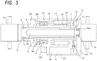
- Fig. 3 is a sectional view taken along line III-III in Figure 2 when the linear actuator of the present embodiment has the minimum stroke.
- Fig. 4 is a sectional view of the linear actuator of the present embodiment when the linear actuator has a maximum stroke.
- the linear actuator of the present invention includes the casings (main bodies) 20, 21 and 22 which accommodate therein main parts in an airtight state, and the hollow rotor (nut section) 10 which is rotatably accommodated in the casings 20, 21 and 22. Further, the linear actuator of the present invention includes: a rotation/linear motion converting section 7 which is arranged in the hollow section of the hollow rotor 10, and which is engaged with a spiral groove formed in the inner peripheral surface of the hollow rotor 10, so as to be linearly moved in the axial direction in the hollow rotor by the rotation of the hollow rotor 10; and the linear motion rod 2 which is connected to the rotation/linear motion converting section 7, and which is extended/housed, in an airtight manner, with respect to the casings according to the linear motion of the rotation/linear motion converting section 7.
- the linear actuator of the present invention includes the first spherical bearing 1a and the second spherical bearing 1b which are respectively provided at an extension side end portion of the linear motion rod 2 and at the casing rear section 22.
- the linear actuator is connected to the vehicle body and the bogie truck of the railway vehicle via the spherical bearings 1a and 1b.
- the side at which the linear motion rod 2 is extended from the hollow rotor that is, the side of the first spherical bearing 1a in Fig. 3 is described as the front side, and the side of the second spherical bearing 1b in Figure 3 is described as the rear side.
- the hollow rotor 10 has an open end portion on the front side thereof and a closed end portion on the rear side thereof, and is accommodated and fixed in the casing by an angular bearing 9 (first rotary support means) so as to be rotatably about the rotary shaft of the hollow rotor with respect to the casing.
- the angular bearing 9 is fixed to the hollow rotor 10 by a bearing fixing nut 8a, and is fixed to the casing central section 21 by a bearing fixing nut 8b.
- a magnet 12 is installed at a part of the outer peripheral surface of the hollow rotor 10 and on the rear side of the position at which the angular bearing 9 is fixed.
- a hollow motor is configured by the stator winding 11 and the magnet 12.
- the rotation/linear motion converting section 7 is engaged with a groove section formed in the inner peripheral surface of the hollow rotor 10, and thereby a mechanism, in which the rotation/linear motion converting section 7 is linearly moved by rotation of the hollow rotor 10 in the axial direction in the hollow rotor 10, is configured.
- a known mechanism, which converts rotation to linear motion can be applied as the rotation/linear motion converting section 7.
- the rotation/linear motion converting section 7 may be configured by a planetary roller screw, or may be a ball screw structure in which balls are circulated between a groove section formed in the inner peripheral surface of the hollow rotor 10, and a groove section formed in the outer peripheral surface of the rotation/linear motion converting section 7.
- the front side of the linear motion rod 2 is extended to the outside of the casing from the open end portion of the casing front section 20.
- the front end portion, which is one end of the linear motion rod 2 is connected to the spherical bearing 1a, and the rear end portion, which is the other end of the linear motion rod 2, is fixed to the rotation/linear motion converting section 7.
- the linear motion rod 2 includes a slide section 6 which cooperates with a linear motion oil seal 3 of the casing front section 20 and thereby slides in the axial direction in an airtight manner.
- the inside of the hollow structure formed by the casings 20, 21 and 22 is sealed by the linear motion oil seal 3 installed at the opening of the casing front section 20, and the slide section 6 of the linear motion rod 2.
- the linear motion rod 2 is supported by a linear motion bearing 4 of the casing front section 20 so as to be linearly movable in the axial direction.
- a rotor end cap 17 is fixed at the rear end side of the hollow rotor 10, and thereby the rear end side is sealed to configure a closed end portion.
- the rear side of the rotor end cap is supported by a bearing 16 (second rotary support means) fixed to a bearing receiving recess 22a which is formed (recessed) in the inner surface (inner wall) of the casing rear section 22 configuring the closed end portion of the casing.
- the rear end portion, which is the closed end portion of the hollow rotor 10 is supported rotatably about the axis of rotation of the hollow rotor 10 with respect to the closed end portion of the casing 22.
- the hollow rotor 10 as a whole is configured to be accommodated in a hollow structure (sealed space) formed by the casings 20, 21 and 22.
- the linear motion oil seal 3 is only the sliding seal mechanism with respect to the operation (linear motion of the linear motion rod 2 and rotation of the hollow rotor 10) of the linear actuator.
- the hollow rotor 10 is mechanically connected, only by the bearing mechanism, to the non-rotating portions, such as the casings 20, 21, 22, and the linear motion rod 2.
- the hollow rotor 10 is not provided with the sliding seal mechanism between itself and the non-rotating portions (the casing, the linear motion rod) which are not rotated with rotation of the hollow rotor 10.
- the linear actuator can be driven in the state where a load (back drive force) applied to external force is reduced as much as possible.
- the angle of rotation of the hollow rotor 10 is detected by a segment type resolver 13 and 14.
- Fig. 5 shows an example of the segment type resolver 13 and 14.
- the resolver rotor section 14 of a segment type VR resolver (segment-type variable reluctance type resolver) is fixed over the entire circumference on the open end portion side of the end surface of the closed end portion of the hollow rotor 10, and on the radially outer side of the outer peripheral surface of the hollow rotor 10.
- the resolver rotor section 14 is fixed and installed on the rotor end cap 17 fixed to the rear end portion side of the hollow rotor 10. Further, as shown in Fig.
- the resolver stator section 13 of the segment resolver is arranged only at a part of the rotation angle range about the axis of the hollow rotor 10.
- a winding section 13a is provided at the position corresponding to each of the sensors 13 and arranged in the terminal box in which the power supply and the signal wire are disposed.
- the angle of rotation of the hollow rotor is detected and outputted to a controller (not shown) so as to be used for motor drive control.
- the rotation angle detection means in the linear actuator of the present invention is not arranged in a manner of being extended to the axial direction rear portion side of the hollow rotor, and hence it is possible to realize downsizing in the axial direction.
- the resolver stator section 13 is not arranged about the entire periphery but arranged only at a position corresponding to a predetermined part of the angle of rotation, and hence it is also possible to realize downsizing in the radial direction at the same time with downsizing in the axial direction.
- the resolver stator section 13 arranged only in the predetermined rotation angle range is configured to be arranged in the inside of the terminal box 18 formed to project to the casing side portion of the linear actuator. This eliminates the necessity that the linear actuator is extended in the radial direction thereof for arrangement of the resolver stator section 13, and hence it is possible to realize downsizing in the radial direction of the axis of rotation of the apparatus.
- the linear actuator of the present invention is assumed to be used for a rocking controller for a railway vehicle and aims at controlling the rotating force. Therefore, the linear actuator does not aim to provide a precise positioning, and hence does not require precise detection of the rotation angle.
- the rotation angle detection means does not need to have a configuration having a resolver stator section which is a detection terminal for the entire circumference of the rotation angle, and hence the detecting section arranged only at a part of the angles of rotation as described in the present invention can attain the purpose as the rotation detecting means. Deterioration of efficiency due to an error of a detected angle is cos (error electrical angle).
- the efficiency deterioration is about 1.5%, and hence the influence of the error of the detected angle is negligible in the rocking controller for the railway vehicle, which is not used for position control but is used for force control.
- the segment VR type resolver is exemplified as the rotation angle detection means, but the present invention is not limited to this.
- the present invention is not limited to this.
- a similar rotation angle detection means is configured by an eddy current sensor, the effect of the present invention can be obtained.
- the effect of the present invention can be obtained by using a rotation angle sensor configured in such a manner that a conductor structure generating an inductance change due to a periodic eddy current based on the rotation angle in the circumferential direction, and the eddy current sensor fixed to the main body at a part of the angular range about the rotation axis of the hollow rotor 10 on the radial direction outer side of the resolver rotor 14, are arranged on the open end portion side of the end surface of the closed end portion of the hollow rotor 10, and on the radially outer side of the outer peripheral surface of the hollow rotor 10. That is, it is possible to realize downsizing in the radial direction and the axial direction of the linear actuator.
- a noncontact labyrinth seal 15 is provided at a portion between the casing central section 21 and the hollow rotors 10, which portion is located between the angular bearing 9, and the magnet 12 and the stator winding 11 (portion in which the hollow motor is formed), and the low viscosity grease is used in this portion.
- the magnet 12 and the stator winding 11 are arranged in the one divided region, while the linear motion oil seal 3, the slide section 6, the rotation/linear motion converting section 7, and the angular bearing 9 are arranged in the other divided region. Further, the rear end portion of the hollow rotor 10 is sealed by the rotor end cap. Thereby, the sealed region 5 is divided into the region in which the rotation/linear motion converting section 7 is installed, and in which many abrasion powders may be most frequently generated, and the region in which the magnet 12 and the stator winding 11 are installed. Therefore, it is possible to reduce the risk that the magnet 12 and the stator winding 11 are brought into contact with the abrasion powders, such as iron powders.
- the abrasion powders such as iron powders.
- the first spherical bearing 1a fixed to the front side end portion of the linear motion rod 2, and the second spherical bearing 1b fixed to the casing rear section 22 are respectively connected to structures, for example a main body and a bogie truck of a railway vehicle, which are to be controlled by the linear actuator. Therefore, relative free rotation between the linear motion rod 2 and the casing rear section 22 is restricted, and the hollow rotor 10 is rotated in the state in which free rotation with respect to the casing of rotation/ linear motion converting section 7 is restrained. Thereby, the linear motion rod 2 is linearly moved in the axial direction by the relative rotation between the rotation/linear motion converting section 7 and the hollow rotor 10.
- the linear actuator of the present invention When the linear actuator of the present invention is used in a rocking controller of a railway vehicle, active control for aerodynamic characteristics during high speed traveling is especially required.
- the active control is required to suppress an instantaneous rolling of a vehicle, which is caused at a time when entering a tunnel in high-speed, or rolling in the last car of a train set due to the influence of Karman's vortex at high-speed traveling or the like, though it does not occur in low-speed traveling.
- the active control for suppressing these kinds of rocking is not required under a condition, such as travelling under a predetermined speed, other than predetermined conditions.
- the linear actuator is driven without applying load (back drive force) to external force as much as possible in the state where the power supply of the linear actuator is turn off.
- the noncontact labyrinth seal 15 is installed on the radial direction outer side of the rotary shaft with respect to the hollow rotor 10, so that the peripheral length of the seal portion is made long.
- low viscosity grease as a noncontact seal is used at the seal portion, and thereby the linear actuator can be driven with a small load against external force.
- the whole of the hollow rotor 10 is accommodated in the sealed space, and a sliding seal mechanism for rotation of the hollow rotor 10 is not provided, but only the linear motion oil seal 3 for linear motion of the linear motion rod 2 is provided as a sliding seal mechanism for driving the linear actuator.
- This configuration also provides the effect that the linear actuator is driven without applying a load (back drive force) to external force as much as possible in the state where the power supply of the linear actuator is turn off.
- the sealed region 5 is formed in the inside of the casing configured by the casing front section 20, the casing central section 21, the casing rear section 22, and the seal structure formed by the slide section 6 of the linear motion rod 2 and the linear motion oil seal 3.
- the linear actuator prevents that outside air is made to flow into or from the sealed region 5 by the pressure fluctuation in the sealed region 5 due to the stroke displacement of the linear motion rod 2 (i.e., the linear actuator of the present invention is not provided with an air breather function).
- the linear actuator of the present invention provides the effect that, even when the linear actuator is used under a conditions of low temperature, such as -20 degrees, lowering of the sliding function due to phenomena, such as freezing of moisture in air entering into the actuator, is not caused, and the good sliding state is maintained. Further, since the main body of the linear actuator of the present invention is sealed against the outside air, moisture, dust, and the like, in the air can be prevented from entering the main body, and hence the stable function of the linear actuator is maintainable.
- air or inert gas such as nitrogen may be used as the gas in the sealed region 5.
- the sealed region 5 is a sealed space in which the product of the volume occupied by the gas and the pressure of the gas is constant. Therefore, when the volume occupied by the gas in the sealed region 5 is changed from V1 to V2, and when the pressure is changed from P1 to P2, the pressure P2 after the volume change is expressed by the following expression.
- ⁇ V represents the amount of change (V2 - V1) from V1 to V2 of the volume occupied by the gas. Since the linear actuator of the present invention is compactly configured, the volume of the casing is small, and the difference (ratio) between V1 and V2 easily becomes large.
- a hollow portion 2a having an opening at the rear end portion as the closed end portion side of the hollow rotor, is formed to extend in the axial direction.
- ⁇ V as the amount of change from V1 of the volume occupies by the gas to V2, which change is caused by the front/rear movement of the linear motion rod, is the same as the volume represented by the product of the cross-sectional area of the linear motion rod 2 with the maximum stroke length.
- V1 becomes large by the volume of the hollow portion 2a, the influence of ⁇ V on P2 can be suppressed.
- a cover such as a bellows, (not shown) is provided between the casing front section 21 and the first spherical bearing 1a to prevent that power dusts, and the like, adhere to the outer surface of the slide section 6.
- a cover such as a bellows, (not shown) is provided between the casing front section 21 and the first spherical bearing 1a to prevent that power dusts, and the like, adhere to the outer surface of the slide section 6.
- an external apparatus such as a pressure generator
- a pressure generator is not required in addition to the main body of the linear actuator.
- pressurized fluid pipes of a drive source which is required in the case of a controller using pressurized fluid, and hence it is possible to provide a linear actuator compact in the total length and outer diameter.
- the configuration of the present embodiment provides a function, as a linear actuator, for applying desired driving force or damping force, and also provides a linear actuator capable of being easily driven without applying large load (back drive force) to external force at the time when the function of the linear actuator is not required.
- the configuration of the present embodiment provides a linear actuator which stably functions with low back drive force under a severe use condition where it is difficult to perform maintenance, such as frequent replacement, and where the temperature changes in the installation and use environment is large (-20°C to 60°C).
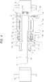
- Fig. 6 shows a schematic view of a rocking controller for a railway vehicle, to which apparatus the linear actuator according to embodiment 1 of the present invention is applied.
- the rocking controller for the railway vehicles of the present embodiment includes the actuator of embodiment 1 of the present invention, which is installed between a bogie truck 35 and a vehicle body 30 of the railway vehicle, and a controller 32 which performs active control for driving a linear actuator 33 to suppress rocking of the vehicle body 30.
- Vibration is transmitted from wheels to the bogie truck 35 via primary springs 36, and the vibration of the bogie truck 35 is transmitted to the vehicle body 30 via secondary springs 34.
- An accelerometer 31 measures acceleration of the vehicle body 30, and the controller 32 actively controls the linear actuator 33 according to the measured acceleration, so as to suppress rocking (vibration) of the vehicle body 30.
- Various known control methods can be applied to the active control by the controller.
- the compact linear actuator of the present invention has a great advantage. Especially under the conditions to which the narrow-gauge standards are widely applied, it is advantageous to apply the compact linear actuator of the present invention to the rocking controller of the vehicle body in a railway vehicle.
- the present invention provides a linear actuator which applies desired driving force or damping force, and also which can be easily driven without applying large load (back drive force) to external force at the time when the function of the linear actuator is not required.
- the present invention provides a rocking controller for a railway vehicle, which is provided with a linear actuator that stably functions with low back drive force even under a severe use condition where it is difficult to perform maintenance, such as frequent replacement, and where the temperature changes in the installation and use environment is large (-20°C to 60°C).
Landscapes
- Engineering & Computer Science (AREA)
- Power Engineering (AREA)
- Microelectronics & Electronic Packaging (AREA)
- Physics & Mathematics (AREA)
- General Physics & Mathematics (AREA)
- Mechanical Engineering (AREA)
- Connection Of Motors, Electrical Generators, Mechanical Devices, And The Like (AREA)
- Transmission Devices (AREA)
- Linear Motors (AREA)
Claims (11)
- Actionneur linéaire (33) comprenant :un rotor creux (10) qui a un aimant (12) fixé sur une partie de sa surface périphérique externe, et une rainure en spirale formée dans sa surface périphérique interne, et a une structure creuse ayant une partie d'extrémité ouverte et une partie d'extrémité fermée ;un corps principal (20, 21, 22, 23) dans lequel le rotor creux (10) est supporté et logé afin de pouvoir tourner autour de l'axe de rotation du rotor creux (10), et qui a un enroulement de stator (11) dans une position faisant face à l'aimant (12) du rotor creux (10) ;une section de conversion de mouvement de rotation/linéaire (7) qui est agencée dans le rotor creux (10) et est mise en prise avec la rainure en spirale pour être déplacée de manière linéaire dans la direction axiale du rotor creux (10) par la rotation du rotor creux (10) ;une tige de mouvement linéaire (2) qui a l'une de ses parties d'extrémité fixée sur la section de conversion de mouvement de rotation/linéaire (7), et son autre partie d'extrémité étendue à partir de la partie d'extrémité ouverte du corps principal (20, 21, 22, 23) et a, sur sa périphérie externe, une section de coulissement (6) réalisée pour coulisser dans la direction axiale via un joint d'étanchéité à l'huile de mouvement linéaire (3) agencée au niveau de la partie d'extrémité ouverte du corps principal (20, 21, 22, 23), de sorte que le joint d'étanchéité à l'huile de mouvement linéaire (3) et la section de coulissement (6) coopèrent entre eux afin de former un espace scellé (5) dans le corps principal (20, 21, 22, 23) ; etun transformateur de type à segment (13, 13a, 14) qui détecte la position de rotation du rotor creux (10) et est configuré par un rotor de transformateur (14) fixé au niveau du côté radial externe de la surface périphérique externe du rotor creux (10) et du côté de la partie d'extrémité ouverte de la surface d'extrémité de la partie d'extrémité fermée du rotor creux (10), et un stator de transformateur (13) fixé sur le corps principal au niveau d'une partie de la plage angulaire autour de l'axe de rotation du rotor creux (10) et du côté radial externe du rotor de transformateur,dans lequel : l'aimant (12) et l'enroulement de stator (11) forment un moteur creux. ;le corps principal (20, 21, 22, 23) comprend un premier moyen de support rotatif (9) qui, du côté de la partie d'extrémité ouverte de la partie formée avec le moteur creux, supporte le rotor creux (10) afin de permettre au rotor creux (10) de tourner autour de l'axe de rotation du rotor creux (10) par rapport au corps principal (20, 21, 22, 23), et un second moyen de support rotatif (16) qui supporte la partie d'extrémité fermée du rotor creux (10) afin de permettre à la partie d'extrémité fermée de tourner autour de l'axe de rotation du rotor creux (10) ;la totalité du rotor creux (10) est logée dans l'espace scellé (5) ;caractérisé en ce que :
la tige de mouvement linéaire (2) comprend une structure creuse (2a) ayant une ouverture au niveau d'une partie d'extrémité arrière en tant que côté partie d'extrémité fermée du rotor creux (10), dans lequel :
l'espace scellé (5), formé par des carters (20, 21, 22) et par le joint d'étanchéité à l'huile de mouvement linéaire et la section de coulissement (6) de la tige de mouvement linéaire (2), qui sont installés au niveau de l'ouverture d'une section avant de carter (20), est divisé en deux régions par un joint d'étanchéité à labyrinthe sans contact (15), où les deux régions comprennent : une région dans laquelle la section de conversion de mouvement de rotation/linéaire (7) est installée, et dans laquelle de nombreuses poudres d'abrasion sont très souvent générées ; et une région dans laquelle l'aimant (12) et l'enroulement de stator (11) sont installés, et où du gaz inerte ou de l'air est utilisé en tant que gaz dans la région scellée. - Actionneur linéaire (33) selon la revendication 1, dans lequel aucun mécanisme de joint d'étanchéité coulissant n'est prévu entre le rotor creux (10) et le corps principal (20, 21, 22, 23) et entre le rotor creux (10) et la tige de mouvement linéaire (2).
- Actionneur linéaire (33) selon la revendication 1 ou la revendication 2, comprenant uniquement le joint d'étanchéité à l'huile de mouvement linéaire (3), en tant que mécanisme de joint d'étanchéité coulissant, pour le mouvement linéaire de la tige de mouvement linéaire (2) et pour la rotation du rotor creux (10).
- Actionneur linéaire (33) selon l'une quelconque des revendications 1 à 3, dans lequel la section de conversion de mouvement de rotation/linéaire (7) est configurée par une vis à rouleaux satellites.
- Actionneur linéaire (33) selon l'une quelconque des revendications 1 à 4, dans lequel la section de conversion de mouvement de rotation/linéaire (7) est configurée par une vis à billes.
- Actionneur linéaire (33) selon l'une quelconque des revendications 1 à 5, dans lequel :le corps principal (20, 21, 22, 23) comprend une boîte à bornes faisant saillie dans la direction perpendiculaire à la direction axiale, etle stator de transformateur (13) est configuré dans la boîte à bornes.
- Actionneur linéaire (33) selon l'une quelconque des revendications 1 à 6, dans lequel le transformateur de type à segment (13, 13a, 14) est configuré par un transformateur VR de type à segment.
- Actionneur linéaire (33) selon l'une quelconque des revendications 1 à 6, comprenant, à la place du transformateur de type à segment, un capteur de rotation configuré par une structure de conducteur qui est agencée au niveau du côté radial externe de la surface périphérique externe du rotor creux (10) et du côté partie d'extrémité ouverte de la surface d'extrémité de la partie d'extrémité fermée du rotor creux (10), afin de provoquer un changement d'inductance dû au courant de Foucault périodique sur la base de l'angle de rotation dans la direction circonférentielle, et un capteur de courant de Foucault fixé sur le corps principal au niveau d'une partie de la plage angulaire autour de l'axe de rotation du rotor creux (10) du côté radialement externe du rotor de transformateur (14).
- Actionneur linéaire (33) selon l'une quelconque des revendications 1 à 8, dans lequel le second moyen de support de rotation (16) est un palier fixé sur un évidement de réception de palier de la paroi interne de la partie d'extrémité fermée du corps principal (20, 21, 22, 23).
- Actionneur linéaire (33) selon l'une quelconque des revendications 1 à 9, dans lequel :
le moteur creux est agencé dans ladite une région divisée, et le premier moyen de support de rotation (1a) est agencé dans l'autre région divisée. - Organe de commande de basculement pour un véhicule ferroviaire comprenant : l'actionneur linéaire (33) selon l'une quelconque des revendications 1 à 10, l'actionneur linéaire (33) étant installé entre un bogie (35) et un corps de véhicule (30) du véhicule ferroviaire ; et un organe de commande pour commander activement l'entraînement de l'actionneur linéaire (33) afin de supprimer le basculement du corps de véhicule (30).
Applications Claiming Priority (2)
| Application Number | Priority Date | Filing Date | Title |
|---|---|---|---|
| JP2013147737 | 2013-07-16 | ||
| PCT/JP2014/003703 WO2015008471A1 (fr) | 2013-07-16 | 2014-07-11 | Actionneur linéaire et dispositif de commande d'oscillation pour une voiture ferroviaire |
Publications (3)
| Publication Number | Publication Date |
|---|---|
| EP3024123A1 EP3024123A1 (fr) | 2016-05-25 |
| EP3024123A4 EP3024123A4 (fr) | 2017-04-12 |
| EP3024123B1 true EP3024123B1 (fr) | 2020-03-18 |
Family
ID=52345948
Family Applications (1)
| Application Number | Title | Priority Date | Filing Date |
|---|---|---|---|
| EP14825671.2A Active EP3024123B1 (fr) | 2013-07-16 | 2014-07-11 | Actionneur linéaire et dispositif de commande d'oscillation pour une voiture ferroviaire |
Country Status (10)
| Country | Link |
|---|---|
| US (1) | US9941767B2 (fr) |
| EP (1) | EP3024123B1 (fr) |
| JP (1) | JP6126223B2 (fr) |
| KR (1) | KR101800318B1 (fr) |
| CN (1) | CN105379079B (fr) |
| AU (1) | AU2014291574B2 (fr) |
| CA (1) | CA2918230C (fr) |
| ES (1) | ES2788656T3 (fr) |
| TW (1) | TWI527344B (fr) |
| WO (1) | WO2015008471A1 (fr) |
Families Citing this family (14)
| Publication number | Priority date | Publication date | Assignee | Title |
|---|---|---|---|---|
| US9849894B2 (en) | 2015-01-19 | 2017-12-26 | Tetra Tech, Inc. | Protective shroud for enveloping light from a light emitter for mapping of a railway track |
| CA2893007C (fr) | 2015-01-19 | 2020-04-28 | Tetra Tech, Inc. | Appareil de synchronisation de capteur et methode |
| US10349491B2 (en) | 2015-01-19 | 2019-07-09 | Tetra Tech, Inc. | Light emission power control apparatus and method |
| CA2893017C (fr) | 2015-01-19 | 2020-03-24 | Tetra Tech, Inc. | Appareil de commande de puissance d'emission de lumiere et methode |
| US10362293B2 (en) | 2015-02-20 | 2019-07-23 | Tetra Tech, Inc. | 3D track assessment system and method |
| US10730538B2 (en) | 2018-06-01 | 2020-08-04 | Tetra Tech, Inc. | Apparatus and method for calculating plate cut and rail seat abrasion based on measurements only of rail head elevation and crosstie surface elevation |
| US11377130B2 (en) | 2018-06-01 | 2022-07-05 | Tetra Tech, Inc. | Autonomous track assessment system |
| US10625760B2 (en) | 2018-06-01 | 2020-04-21 | Tetra Tech, Inc. | Apparatus and method for calculating wooden crosstie plate cut measurements and rail seat abrasion measurements based on rail head height |
| US10807623B2 (en) | 2018-06-01 | 2020-10-20 | Tetra Tech, Inc. | Apparatus and method for gathering data from sensors oriented at an oblique angle relative to a railway track |
| WO2020232431A1 (fr) | 2019-05-16 | 2020-11-19 | Tetra Tech, Inc. | Système et procédé de génération et d'interprétation de nuages de points d'un couloir ferroviaire le long d'un trajet d'étude |
| FR3101596B1 (fr) * | 2019-10-08 | 2022-02-25 | Alstom Transp Tech | Moteur et/ou générateur pour un véhicule ferroviaire, bogie et véhicule ferroviaire associés |
| JP7834969B2 (ja) * | 2021-03-22 | 2026-03-25 | 日本精工株式会社 | アクチュエータ |
| JP7647224B2 (ja) * | 2021-03-25 | 2025-03-18 | 日本精工株式会社 | モータ |
| DE102022206871A1 (de) * | 2022-07-06 | 2024-01-11 | Robert Bosch Gesellschaft mit beschränkter Haftung | Elektromechanischer Linearaktuator mit Hohlwellenmotor |
Family Cites Families (11)
| Publication number | Priority date | Publication date | Assignee | Title |
|---|---|---|---|---|
| JPH0635856Y2 (ja) | 1987-07-10 | 1994-09-21 | 株式会社東海理化電機製作所 | ステアリングシャフト回りの構造 |
| JP2002112507A (ja) | 2000-09-29 | 2002-04-12 | Hitachi Ltd | ブラシレスモータ |
| JP4548923B2 (ja) | 2000-10-20 | 2010-09-22 | 株式会社アイエイアイ | アクチュエータ |
| JP3687622B2 (ja) | 2002-04-01 | 2005-08-24 | 日産自動車株式会社 | 回転電機のロータ位置検出方法 |
| JP4225150B2 (ja) | 2003-08-12 | 2009-02-18 | アイシン・エィ・ダブリュ株式会社 | 電動駆動制御装置及び電動駆動制御方法 |
| DE602004028872D1 (de) * | 2004-03-31 | 2010-10-07 | Danaher Motion Stockholm Ab | Elektrisches betätigungsglied |
| US7389709B2 (en) | 2004-06-30 | 2008-06-24 | Moog Inc. | Reverse transfer system ball-screw, and electro-mechanical actuator employing same |
| US7780357B2 (en) * | 2005-02-01 | 2010-08-24 | The Timken Company | Bearing with cage-mounted sensors |
| JP4982593B2 (ja) | 2010-07-09 | 2012-07-25 | 日本ムーグ株式会社 | リニアアクチュエータ及び鉄道車両用の揺動制御装置 |
| US20120176006A1 (en) * | 2011-01-06 | 2012-07-12 | Remy Technologies, L.L.C. | Electric machine having integrated resolver |
| WO2013118319A1 (fr) * | 2012-02-08 | 2013-08-15 | 日本精工株式会社 | Actionneur, stator, moteur, mécanisme de conversion de mouvement rotatif-linéaire et actionneur linéaire |
-
2014
- 2014-07-11 CA CA2918230A patent/CA2918230C/fr active Active
- 2014-07-11 JP JP2015527174A patent/JP6126223B2/ja active Active
- 2014-07-11 EP EP14825671.2A patent/EP3024123B1/fr active Active
- 2014-07-11 AU AU2014291574A patent/AU2014291574B2/en active Active
- 2014-07-11 US US14/904,481 patent/US9941767B2/en active Active
- 2014-07-11 CN CN201480040522.2A patent/CN105379079B/zh active Active
- 2014-07-11 ES ES14825671T patent/ES2788656T3/es active Active
- 2014-07-11 WO PCT/JP2014/003703 patent/WO2015008471A1/fr not_active Ceased
- 2014-07-11 KR KR1020167001686A patent/KR101800318B1/ko active Active
- 2014-07-16 TW TW103124388A patent/TWI527344B/zh active
Non-Patent Citations (1)
| Title |
|---|
| None * |
Also Published As
| Publication number | Publication date |
|---|---|
| CA2918230C (fr) | 2017-02-21 |
| US20160149466A1 (en) | 2016-05-26 |
| US9941767B2 (en) | 2018-04-10 |
| WO2015008471A1 (fr) | 2015-01-22 |
| JPWO2015008471A1 (ja) | 2017-03-02 |
| KR101800318B1 (ko) | 2017-11-22 |
| AU2014291574A1 (en) | 2016-02-04 |
| CN105379079A (zh) | 2016-03-02 |
| JP6126223B2 (ja) | 2017-05-10 |
| KR20160022895A (ko) | 2016-03-02 |
| ES2788656T3 (es) | 2020-10-22 |
| AU2014291574B2 (en) | 2016-12-22 |
| EP3024123A1 (fr) | 2016-05-25 |
| EP3024123A4 (fr) | 2017-04-12 |
| TWI527344B (zh) | 2016-03-21 |
| CN105379079B (zh) | 2018-04-03 |
| TW201517466A (zh) | 2015-05-01 |
| CA2918230A1 (fr) | 2015-01-22 |
Similar Documents
| Publication | Publication Date | Title |
|---|---|---|
| EP3024123B1 (fr) | Actionneur linéaire et dispositif de commande d'oscillation pour une voiture ferroviaire | |
| EP2592725B1 (fr) | Actionneur linéaire et dispositif de maîtrise du basculement pour véhicule ferroviaire | |
| CN102123833B (zh) | 具有第一电机和第二电机的驱动单元 | |
| JP2728648B2 (ja) | 電気エネルギーの発生が可能な減摩軸受 | |
| JP5126537B2 (ja) | 電磁サスペンション装置 | |
| CN102748451A (zh) | 一种采用串联式行星滚柱丝杠副的折返式直线机电作动器 | |
| CN202746527U (zh) | 一种采用串联式行星滚柱丝杠副的折返式直线机电作动器 | |
| JP2019519419A (ja) | 操作装置を有するステアリングシステム並びに操作装置を有するステアリングシステムの使用 | |
| JP2009071919A (ja) | 中空アクチュエータ | |
| JP4271604B2 (ja) | 電磁緩衝器 | |
| ES2870664T3 (es) | Dispositivo de frenado para un eje giratorio o carril de desplazamiento | |
| CN104613951B (zh) | 一种磁路解耦的磁悬浮陀螺仪 | |
| CN121520320A (zh) | 一种作动器总成、悬架总成及车辆 | |
| CN120090420A (zh) | 一种内置环形磁轨动力的真空五自由度磁悬浮发电装置 | |
| JP2020097269A (ja) | 操舵機能付ハブユニットおよび操舵システム | |
| JP2009121538A (ja) | ボールねじ装置 | |
| JP2010253997A (ja) | 鉄道車両用振動制御装置 |
Legal Events
| Date | Code | Title | Description |
|---|---|---|---|
| PUAI | Public reference made under article 153(3) epc to a published international application that has entered the european phase |
Free format text: ORIGINAL CODE: 0009012 |
|
| 17P | Request for examination filed |
Effective date: 20160126 |
|
| AK | Designated contracting states |
Kind code of ref document: A1 Designated state(s): AL AT BE BG CH CY CZ DE DK EE ES FI FR GB GR HR HU IE IS IT LI LT LU LV MC MK MT NL NO PL PT RO RS SE SI SK SM TR |
|
| AX | Request for extension of the european patent |
Extension state: BA ME |
|
| DAX | Request for extension of the european patent (deleted) | ||
| A4 | Supplementary search report drawn up and despatched |
Effective date: 20170310 |
|
| RIC1 | Information provided on ipc code assigned before grant |
Ipc: H02K 5/10 20060101ALI20170306BHEP Ipc: H02K 11/225 20160101ALI20170306BHEP Ipc: H02K 5/12 20060101ALI20170306BHEP Ipc: H02K 5/173 20060101ALI20170306BHEP Ipc: B61F 5/24 20060101ALI20170306BHEP Ipc: H02K 7/06 20060101AFI20170306BHEP |
|
| STAA | Information on the status of an ep patent application or granted ep patent |
Free format text: STATUS: EXAMINATION IS IN PROGRESS |
|
| 17Q | First examination report despatched |
Effective date: 20180112 |
|
| RAP1 | Party data changed (applicant data changed or rights of an application transferred) |
Owner name: MOOG JAPAN LTD. Owner name: NIPPON STEEL CORPORATION |
|
| GRAP | Despatch of communication of intention to grant a patent |
Free format text: ORIGINAL CODE: EPIDOSNIGR1 |
|
| STAA | Information on the status of an ep patent application or granted ep patent |
Free format text: STATUS: GRANT OF PATENT IS INTENDED |
|
| RIC1 | Information provided on ipc code assigned before grant |
Ipc: G01D 5/20 20060101ALI20190913BHEP Ipc: H02K 11/225 20160101ALI20190913BHEP Ipc: H02K 5/173 20060101ALI20190913BHEP Ipc: H02K 5/12 20060101ALI20190913BHEP Ipc: H02K 7/06 20060101AFI20190913BHEP Ipc: B61F 5/24 20060101ALI20190913BHEP Ipc: H02K 5/10 20060101ALI20190913BHEP |
|
| INTG | Intention to grant announced |
Effective date: 20191021 |
|
| GRAS | Grant fee paid |
Free format text: ORIGINAL CODE: EPIDOSNIGR3 |
|
| GRAA | (expected) grant |
Free format text: ORIGINAL CODE: 0009210 |
|
| STAA | Information on the status of an ep patent application or granted ep patent |
Free format text: STATUS: THE PATENT HAS BEEN GRANTED |
|
| AK | Designated contracting states |
Kind code of ref document: B1 Designated state(s): AL AT BE BG CH CY CZ DE DK EE ES FI FR GB GR HR HU IE IS IT LI LT LU LV MC MK MT NL NO PL PT RO RS SE SI SK SM TR |
|
| REG | Reference to a national code |
Ref country code: GB Ref legal event code: FG4D |
|
| REG | Reference to a national code |
Ref country code: AT Ref legal event code: REF Ref document number: 1247061 Country of ref document: AT Kind code of ref document: T Effective date: 20200415 Ref country code: IE Ref legal event code: FG4D |
|
| REG | Reference to a national code |
Ref country code: DE Ref legal event code: R096 Ref document number: 602014062609 Country of ref document: DE |
|
| REG | Reference to a national code |
Ref country code: CH Ref legal event code: NV Representative=s name: BOVARD AG PATENT- UND MARKENANWAELTE, CH |
|
| PG25 | Lapsed in a contracting state [announced via postgrant information from national office to epo] |
Ref country code: FI Free format text: LAPSE BECAUSE OF FAILURE TO SUBMIT A TRANSLATION OF THE DESCRIPTION OR TO PAY THE FEE WITHIN THE PRESCRIBED TIME-LIMIT Effective date: 20200318 Ref country code: NO Free format text: LAPSE BECAUSE OF FAILURE TO SUBMIT A TRANSLATION OF THE DESCRIPTION OR TO PAY THE FEE WITHIN THE PRESCRIBED TIME-LIMIT Effective date: 20200618 Ref country code: RS Free format text: LAPSE BECAUSE OF FAILURE TO SUBMIT A TRANSLATION OF THE DESCRIPTION OR TO PAY THE FEE WITHIN THE PRESCRIBED TIME-LIMIT Effective date: 20200318 |
|
| REG | Reference to a national code |
Ref country code: NL Ref legal event code: MP Effective date: 20200318 |
|
| PG25 | Lapsed in a contracting state [announced via postgrant information from national office to epo] |
Ref country code: GR Free format text: LAPSE BECAUSE OF FAILURE TO SUBMIT A TRANSLATION OF THE DESCRIPTION OR TO PAY THE FEE WITHIN THE PRESCRIBED TIME-LIMIT Effective date: 20200619 Ref country code: HR Free format text: LAPSE BECAUSE OF FAILURE TO SUBMIT A TRANSLATION OF THE DESCRIPTION OR TO PAY THE FEE WITHIN THE PRESCRIBED TIME-LIMIT Effective date: 20200318 Ref country code: LV Free format text: LAPSE BECAUSE OF FAILURE TO SUBMIT A TRANSLATION OF THE DESCRIPTION OR TO PAY THE FEE WITHIN THE PRESCRIBED TIME-LIMIT Effective date: 20200318 Ref country code: SE Free format text: LAPSE BECAUSE OF FAILURE TO SUBMIT A TRANSLATION OF THE DESCRIPTION OR TO PAY THE FEE WITHIN THE PRESCRIBED TIME-LIMIT Effective date: 20200318 Ref country code: BG Free format text: LAPSE BECAUSE OF FAILURE TO SUBMIT A TRANSLATION OF THE DESCRIPTION OR TO PAY THE FEE WITHIN THE PRESCRIBED TIME-LIMIT Effective date: 20200618 |
|
| REG | Reference to a national code |
Ref country code: LT Ref legal event code: MG4D |
|
| PG25 | Lapsed in a contracting state [announced via postgrant information from national office to epo] |
Ref country code: NL Free format text: LAPSE BECAUSE OF FAILURE TO SUBMIT A TRANSLATION OF THE DESCRIPTION OR TO PAY THE FEE WITHIN THE PRESCRIBED TIME-LIMIT Effective date: 20200318 |
|
| REG | Reference to a national code |
Ref country code: ES Ref legal event code: FG2A Ref document number: 2788656 Country of ref document: ES Kind code of ref document: T3 Effective date: 20201022 |
|
| PG25 | Lapsed in a contracting state [announced via postgrant information from national office to epo] |
Ref country code: RO Free format text: LAPSE BECAUSE OF FAILURE TO SUBMIT A TRANSLATION OF THE DESCRIPTION OR TO PAY THE FEE WITHIN THE PRESCRIBED TIME-LIMIT Effective date: 20200318 Ref country code: CZ Free format text: LAPSE BECAUSE OF FAILURE TO SUBMIT A TRANSLATION OF THE DESCRIPTION OR TO PAY THE FEE WITHIN THE PRESCRIBED TIME-LIMIT Effective date: 20200318 Ref country code: LT Free format text: LAPSE BECAUSE OF FAILURE TO SUBMIT A TRANSLATION OF THE DESCRIPTION OR TO PAY THE FEE WITHIN THE PRESCRIBED TIME-LIMIT Effective date: 20200318 Ref country code: PT Free format text: LAPSE BECAUSE OF FAILURE TO SUBMIT A TRANSLATION OF THE DESCRIPTION OR TO PAY THE FEE WITHIN THE PRESCRIBED TIME-LIMIT Effective date: 20200812 Ref country code: EE Free format text: LAPSE BECAUSE OF FAILURE TO SUBMIT A TRANSLATION OF THE DESCRIPTION OR TO PAY THE FEE WITHIN THE PRESCRIBED TIME-LIMIT Effective date: 20200318 Ref country code: SM Free format text: LAPSE BECAUSE OF FAILURE TO SUBMIT A TRANSLATION OF THE DESCRIPTION OR TO PAY THE FEE WITHIN THE PRESCRIBED TIME-LIMIT Effective date: 20200318 Ref country code: IS Free format text: LAPSE BECAUSE OF FAILURE TO SUBMIT A TRANSLATION OF THE DESCRIPTION OR TO PAY THE FEE WITHIN THE PRESCRIBED TIME-LIMIT Effective date: 20200718 Ref country code: SK Free format text: LAPSE BECAUSE OF FAILURE TO SUBMIT A TRANSLATION OF THE DESCRIPTION OR TO PAY THE FEE WITHIN THE PRESCRIBED TIME-LIMIT Effective date: 20200318 |
|
| REG | Reference to a national code |
Ref country code: DE Ref legal event code: R097 Ref document number: 602014062609 Country of ref document: DE |
|
| PLBE | No opposition filed within time limit |
Free format text: ORIGINAL CODE: 0009261 |
|
| STAA | Information on the status of an ep patent application or granted ep patent |
Free format text: STATUS: NO OPPOSITION FILED WITHIN TIME LIMIT |
|
| PG25 | Lapsed in a contracting state [announced via postgrant information from national office to epo] |
Ref country code: DK Free format text: LAPSE BECAUSE OF FAILURE TO SUBMIT A TRANSLATION OF THE DESCRIPTION OR TO PAY THE FEE WITHIN THE PRESCRIBED TIME-LIMIT Effective date: 20200318 |
|
| 26N | No opposition filed |
Effective date: 20201221 |
|
| PG25 | Lapsed in a contracting state [announced via postgrant information from national office to epo] |
Ref country code: PL Free format text: LAPSE BECAUSE OF FAILURE TO SUBMIT A TRANSLATION OF THE DESCRIPTION OR TO PAY THE FEE WITHIN THE PRESCRIBED TIME-LIMIT Effective date: 20200318 Ref country code: MC Free format text: LAPSE BECAUSE OF FAILURE TO SUBMIT A TRANSLATION OF THE DESCRIPTION OR TO PAY THE FEE WITHIN THE PRESCRIBED TIME-LIMIT Effective date: 20200318 |
|
| REG | Reference to a national code |
Ref country code: BE Ref legal event code: MM Effective date: 20200731 |
|
| PG25 | Lapsed in a contracting state [announced via postgrant information from national office to epo] |
Ref country code: LU Free format text: LAPSE BECAUSE OF NON-PAYMENT OF DUE FEES Effective date: 20200711 |
|
| PG25 | Lapsed in a contracting state [announced via postgrant information from national office to epo] |
Ref country code: BE Free format text: LAPSE BECAUSE OF NON-PAYMENT OF DUE FEES Effective date: 20200731 Ref country code: SI Free format text: LAPSE BECAUSE OF FAILURE TO SUBMIT A TRANSLATION OF THE DESCRIPTION OR TO PAY THE FEE WITHIN THE PRESCRIBED TIME-LIMIT Effective date: 20200318 |
|
| PG25 | Lapsed in a contracting state [announced via postgrant information from national office to epo] |
Ref country code: IE Free format text: LAPSE BECAUSE OF NON-PAYMENT OF DUE FEES Effective date: 20200711 |
|
| REG | Reference to a national code |
Ref country code: AT Ref legal event code: UEP Ref document number: 1247061 Country of ref document: AT Kind code of ref document: T Effective date: 20200318 |
|
| PG25 | Lapsed in a contracting state [announced via postgrant information from national office to epo] |
Ref country code: TR Free format text: LAPSE BECAUSE OF FAILURE TO SUBMIT A TRANSLATION OF THE DESCRIPTION OR TO PAY THE FEE WITHIN THE PRESCRIBED TIME-LIMIT Effective date: 20200318 Ref country code: MT Free format text: LAPSE BECAUSE OF FAILURE TO SUBMIT A TRANSLATION OF THE DESCRIPTION OR TO PAY THE FEE WITHIN THE PRESCRIBED TIME-LIMIT Effective date: 20200318 Ref country code: CY Free format text: LAPSE BECAUSE OF FAILURE TO SUBMIT A TRANSLATION OF THE DESCRIPTION OR TO PAY THE FEE WITHIN THE PRESCRIBED TIME-LIMIT Effective date: 20200318 |
|
| PG25 | Lapsed in a contracting state [announced via postgrant information from national office to epo] |
Ref country code: MK Free format text: LAPSE BECAUSE OF FAILURE TO SUBMIT A TRANSLATION OF THE DESCRIPTION OR TO PAY THE FEE WITHIN THE PRESCRIBED TIME-LIMIT Effective date: 20200318 Ref country code: AL Free format text: LAPSE BECAUSE OF FAILURE TO SUBMIT A TRANSLATION OF THE DESCRIPTION OR TO PAY THE FEE WITHIN THE PRESCRIBED TIME-LIMIT Effective date: 20200318 |
|
| PGFP | Annual fee paid to national office [announced via postgrant information from national office to epo] |
Ref country code: ES Payment date: 20250819 Year of fee payment: 12 |
|
| PGFP | Annual fee paid to national office [announced via postgrant information from national office to epo] |
Ref country code: DE Payment date: 20250728 Year of fee payment: 12 |
|
| PGFP | Annual fee paid to national office [announced via postgrant information from national office to epo] |
Ref country code: IT Payment date: 20250731 Year of fee payment: 12 |
|
| PGFP | Annual fee paid to national office [announced via postgrant information from national office to epo] |
Ref country code: GB Payment date: 20250724 Year of fee payment: 12 |
|
| PGFP | Annual fee paid to national office [announced via postgrant information from national office to epo] |
Ref country code: FR Payment date: 20250723 Year of fee payment: 12 Ref country code: AT Payment date: 20250721 Year of fee payment: 12 |
|
| PGFP | Annual fee paid to national office [announced via postgrant information from national office to epo] |
Ref country code: CH Payment date: 20250801 Year of fee payment: 12 |