EP3024309A1 - Système d'installation électronique, aéronef ou engin spatial et procédé - Google Patents
Système d'installation électronique, aéronef ou engin spatial et procédé Download PDFInfo
- Publication number
- EP3024309A1 EP3024309A1 EP14194271.4A EP14194271A EP3024309A1 EP 3024309 A1 EP3024309 A1 EP 3024309A1 EP 14194271 A EP14194271 A EP 14194271A EP 3024309 A1 EP3024309 A1 EP 3024309A1
- Authority
- EP
- European Patent Office
- Prior art keywords
- wiring configuration
- slots
- installation
- slot
- electronics
- Prior art date
- Legal status (The legal status is an assumption and is not a legal conclusion. Google has not performed a legal analysis and makes no representation as to the accuracy of the status listed.)
- Granted
Links
Images
Classifications
-
- H—ELECTRICITY
- H05—ELECTRIC TECHNIQUES NOT OTHERWISE PROVIDED FOR
- H05K—PRINTED CIRCUITS; CASINGS OR CONSTRUCTIONAL DETAILS OF ELECTRIC APPARATUS; MANUFACTURE OF ASSEMBLAGES OF ELECTRICAL COMPONENTS
- H05K7/00—Constructional details common to different types of electric apparatus
- H05K7/14—Mounting supporting structure in casing or on frame or rack
- H05K7/1438—Back panels or connecting means therefor; Terminals; Coding means to avoid wrong insertion
- H05K7/1457—Power distribution arrangements
-
- B—PERFORMING OPERATIONS; TRANSPORTING
- B60—VEHICLES IN GENERAL
- B60R—VEHICLES, VEHICLE FITTINGS, OR VEHICLE PARTS, NOT OTHERWISE PROVIDED FOR
- B60R16/00—Electric or fluid circuits specially adapted for vehicles and not otherwise provided for; Arrangement of elements of electric or fluid circuits specially adapted for vehicles and not otherwise provided for
- B60R16/02—Electric or fluid circuits specially adapted for vehicles and not otherwise provided for; Arrangement of elements of electric or fluid circuits specially adapted for vehicles and not otherwise provided for electric constitutive elements
- B60R16/03—Electric or fluid circuits specially adapted for vehicles and not otherwise provided for; Arrangement of elements of electric or fluid circuits specially adapted for vehicles and not otherwise provided for electric constitutive elements for supply of electrical power to vehicle subsystems or for
-
- H—ELECTRICITY
- H05—ELECTRIC TECHNIQUES NOT OTHERWISE PROVIDED FOR
- H05K—PRINTED CIRCUITS; CASINGS OR CONSTRUCTIONAL DETAILS OF ELECTRIC APPARATUS; MANUFACTURE OF ASSEMBLAGES OF ELECTRICAL COMPONENTS
- H05K7/00—Constructional details common to different types of electric apparatus
- H05K7/14—Mounting supporting structure in casing or on frame or rack
- H05K7/1422—Printed circuit boards receptacles, e.g. stacked structures, electronic circuit modules or box like frames
- H05K7/1427—Housings
- H05K7/1428—Housings for small modular apparatus with terminal block
-
- H—ELECTRICITY
- H05—ELECTRIC TECHNIQUES NOT OTHERWISE PROVIDED FOR
- H05K—PRINTED CIRCUITS; CASINGS OR CONSTRUCTIONAL DETAILS OF ELECTRIC APPARATUS; MANUFACTURE OF ASSEMBLAGES OF ELECTRICAL COMPONENTS
- H05K7/00—Constructional details common to different types of electric apparatus
- H05K7/14—Mounting supporting structure in casing or on frame or rack
- H05K7/1438—Back panels or connecting means therefor; Terminals; Coding means to avoid wrong insertion
- H05K7/1459—Circuit configuration, e.g. routing signals
Definitions
- the invention relates to an electronics installation system, especially for an aircraft or spacecraft. Furthermore, the present invention relates to an aircraft or spacecraft and a method for installing electronics, especially in an aircraft or spacecraft.
- electronic devices can be used for control of rudders, flaps and the like. Furthermore, electronic devices can be used for cabin lighting, passenger information and the like. Further applications of electronic devices in an aircraft include infotainment systems and other passenger services like on board internet access.
- the present invention provides an electronics installation system according to claim 1, an aircraft or spacecraft according to claim 11 and a method for installing electronics according to claim 12.
- the present invention provides:
- the present invention furthermore provides:
- the idea behind the present invention is to create a highly standardized, easily reconfigurable electronics installation system for the installation of electronic equipment especially in an aircraft or spacecraft, without the disadvantages of the complex customized wiring associated with today's solutions.
- the wiring between equipment locations or installation slots remains unchanged, regardless of which equipment is installed in the respective location or installation slot.
- Equipment or electronic module interconnection re-configuration is achieved by exchanging wiring configuration modules located in pre-defined locations or wiring configuration slots within the mechanical installation structure, e.g. the monument or electronics bay of the respective aircraft or spacecraft.
- Each installation slot has at least one data connection or channel for data transmission. These data connections are routed from each installation slot, via a connection matrix to at least one wiring configuration module installed in the mechanical installation structure in specific wiring configuration slots. This wiring configuration module can be exchanged in case alternative interconnectivity between equipment inside the mechanical installation structure is needed. This approach allows the same mechanical installation structure to be used on all aircraft of the same type, regardless of aircraft systems fit or configuration.
- connection matrix comprises a flexible circuit.
- a flexible circuit or flexi circuit provides connections between the different slots in the mechanical installation structure with little added weight.
- connection matrix comprises a printed circuit board.
- the printed circuit board allows providing rigid and robust data connections.
- connection matrix is embedded in the mechanical installation structure. Integration the connection matrix in the mechanical installation structure allows hiding the data connections which provides a clean mechanical installation structure with little complexity.
- the data connections comprise optical fibre connections.
- Optical fibre connections allow transmitting data at a high bandwidth.
- the data connections comprise electrically conductive connections.
- electrically conductive connections By using electrically conductive connections existing equipment can easily be integrated in the electronics installation system.
- the mechanical installation structure comprises at least two wiring configuration slots.
- the connection matrix comprises at least one data connection between the at least two wiring configuration slots. This allows providing separate and/or redundant networks in the electronics installation system.
- the mechanical installation structure comprises at least one power supply slot.
- the connection matrix comprises power lines configured to connect each one of the installation slots and each one of the configuration slots with at least one of the power supply slots. Integrating the power supply into the mechanical installation structure and the connection matrix allows providing a compact electronics installation system.
- the power lines comprise a power bus configured to connect a plurality of the installation slots and/or the configuration slots with at least one of the power supply slots. Providing a power bus further reduces system complexity.
- the power bus comprises at least on protection unit configured to protect the power bus in case of a failure of an electronic module and/or a wiring configuration module. This allows further providing electric power to electronic modules or wiring configuration modules even if one of the electronic modules or wiring configuration modules fails and e.g. short circuits the power bus.
- the electronics installation system comprises at least one power supply unit installed in one of the power supply slots and coupled to the power lines and configured to provide electrical power via the power lines.
- the electronics installation system comprises at least one wiring configuration module installed in one of the configuration slots and coupled to the data connections of the respective configuration slot, the wiring configuration module comprising internal interconnection paths providing data communication between at least one data connection of the respective wiring configuration slot and at least one other data connection of the respective wiring configuration slot.
- the wiring configuration module comprises an ARINC 836 interconnection-box. This allows flexibly interconnecting different data connections of different installation slots and thereby providing a direct data connection between said installation slots.
- the at least one wiring configuration module comprises static and/or predefined internal interconnection paths. This allows providing a wiring configuration module of low complexity which can simply be exchanged for another wiring configuration module if the interconnections of the data connections have to be changed.
- the at least one wiring configuration module comprises configurable internal interconnection paths configurable to interconnect specific data connections in the respective configuration slot. This allows flexibly adapting the interconnections between the data connections without exchanging the wiring configuration module.
- Fig. 1 shows a block diagram of an exemplary embodiment of an electronics installation system 1 according to the present invention.
- the electronics installation system 1 of Fig. 1 comprises a mechanical installation structure 3 which is shown as a square structure comprising a plurality of installation slots 4-1- 4-n. Two of the installation slots are shown in each one of the corners of the mechanical installation structure 3, and only the two installation slots 4-1- 4-2 in the upper left corner of the mechanical installation structure 3 and the two installation slots 4-(n-1) and 4-n in the lower right corner of the mechanical installation structure 3 are provided with reference signs for sake of clarity. Further installation slots 4-1- 4-n are indicated by three dots between the upper installation slots and by three dots between the lower installation slots.
- the second slot 6-1 in the lower left corner is not configured as an installation slot 4-1- 4-n but as a wiring configuration slot 6-1.
- a slot in this context refers to a location or a space in the mechanical installation structure 3 where a module can be installed.
- a slot can comprise every necessary installation aid, like e.g. mechanical fixation elements, or electric connection means.
- a slot can for example comprise snap in fixation elements which fix a module in its position once inserted in to the slot.
- a slot can comprise connectors or plugs, which automatically slide into the respective counterpart in a module when said module is inserted into the slot.
- a slot can comprise rails or guides which allow sliding a module into the respective slot and automatically position the module in the slot such that the mechanical fixation elements and the plugs or connectors rest in the correct position.
- connection matrix 8 which in Fig. 1 comprises seven data connections 9-1 - 9-7.
- Each one of the data connections 9-1- 9-7 connects one of the installation slots 4-1- 4-n with the wiring configuration slot 6-1. Consequently, the wiring configuration slot 6-1 is coupled with every single one of the installation slots 4-1 - 4-n by a data connection 9-1- 9-7.
- the mechanical installation structure 3 can comprise more than one wiring configuration slot 6-1.
- connection matrix 8 can be a structure which is added to the mechanical installation structure 3 and which comprises the respective data connections 9-1- 9-7.
- the connection matrix 8 can be a flexible circuit or flexi circuit, which includes optical fibres or conductive traces like copper traces.
- the connection matrix 8 can at least partially comprise a printed circuit board, for example a FR4-based printed circuit board.
- the connection matrix 8 can be at least partially integrated into the mechanical installation structure 3.
- the respective data connections 9-1- 9-7 would be integrated e.g. in a frame of the mechanical installation structure 3, or the like.
- every single data connection 9-1- 9-7 can comprise a plurality of single physical data lines.
- a single data connection 9-1- 9-7 can comprise more than fifty optical fibres, e.g. 100 optical fibres.
- every single data connection 9-1- 9-7 can comprise conductive data lines, like e.g. copper wires or copper traces on a printed circuit board or a flexible circuit.
- the mechanical installation structure 3 can e.g. be embodied as an electronics bay or monument of an aircraft 2 or spacecraft.
- an electronics bay can be installed in the fuselage of the aircraft 2 and accommodates a plurality of electronic modules 5-1- 5-n which each provide specific functions in the aircraft.
- Such functions can e.g. be related to the manoeuvring of the aircraft 2, cabin functions of the aircraft 2, like e.g. lightning and climate control, passenger entertainment and information or the like.
- the single electronic modules 5-1 - 5-n need to be connected to other electronic modules 5-1 - 5-n via data connections 9-1 - 9-7.
- These interconnections between the single electronic modules 5-1 - 5-n can be provided by a wiring configuration module 7-1 - 7-2 (see Fig. 4 ), which in the wiring configuration slot 6-1 internally interconnects predefined data connections 9-1 - 9-7 to each other and therefore provides direct data transmission between the respective electronic modules 5-1 - 5-n or forms data networks or data busses.
- a new electronics module 5-1- 5-n is added to the mechanical installation structure 3 into a spare installation slot 4-1- 4-n a data connection 9-1- 9-7 is already provided in said installation slot 4-1- 4-n. Therefore, to connect the newly added electronics module 5-1- 5-n to a network or another electronics module 5-1- 5-n the respective wiring configuration module 7-1- 7-2 has to be adapted to interconnect the data connection 9-1- 9-7 of the newly added electronics module 5-1- 5-n to the required data connection 9-1- 9-7.
- the wiring configuration module 7-1- 7-2 could comprise configurable internal interconnection paths 17-1 - 17-3 (see Fig. 4 ) which can be changed and adapted without removing or exchanging the wiring configuration module 7-1- 7-2.
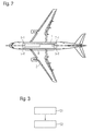
- Fig. 2 shows a block diagram of an exemplary embodiment of an aircraft 2 according to the present invention.
- the aircraft 2 of Fig. 2 is a jet-type aircraft with two turbines, one on each wing.
- This type of aircraft 2 is just an exemplary selection. It is apparent that the present invention can be used with any type of aircraft. In fact the present invention can also be used with other applications, like e.g. trains, busses, or other vehicles.
- the aircraft comprises an electronics installation system 1 according to the present invention, which is only shown as an abstract block diagram for ease of understanding.
- the electronics installation system 1 comprises a mechanical installation structure (not explicitly shown) with one wiring configuration slot and three installation slots, which are not explicitly provided with reference signs for sake of simplicity.
- electronic modules 5-1- 5-7 are provided, which are connected by data connections with a wiring configuration module 7-1 in the wiring configuration slot.
- wiring configuration module 7-1 all data connections are coupled together to form a data bus.
- the number and arrangement of the electronic modules 5-1- 5-7 and the wiring configuration module 7-1 in Fig. 2 is just exemplary and is used to show the concept of the present invention.
- more or less electronic modules 5-1- 5-7 or more wiring configuration modules can be installed in the mechanical installation structure 3.
- an aircraft 2 can comprise more than one electronics installation system 1.
- a plurality of electronics installation systems 1 can be distributed throughout the fuselage of the aircraft 2.
- the distributed electronics installation systems 1 can be coupled to each other by high speed data connections to provide data communication between the electronic modules 5-1- 5-n installed in different electronics installation systems 1.
- data connection refers to all kinds of data connections ranging from single optical or conductive data lines or traces to a plurality of optical or conductive data lines or traces which can be combined into one data connection.
- Fig. 3 shows a flow diagram of an exemplary embodiment of a method according to the present invention.
- the method comprises providing S1 a plurality of installation slots 4-1 - 4-n each configured to receive an electronic module 5-1 - 5-7 and at least one wiring configuration slot 6-1- 6-2 configured to receive a wiring configuration module 7-1- 7-2 in at least one mechanical installation structure 3.
- the method further comprises providing S2 a plurality of data connections 9-1 - 9-14, wherein at least one data connection 9-1- 9-14 is provided between each one of the installation slots 4-1- 4-n and at least one wiring configuration slot 6-1- 6-2.
- the data connections 9-1- 9-14 can be provided as single optical or conductive data lines or traces or a plurality of optical or conductive data lines or traces which can be combined into one data connection 9-1- 9-14. Furthermore, the data connections can be provided as a connection matrix 8, which can be integrated into the structure of the mechanical installation structure 3. Alternatively, the connection matrix 8 can be provided as a flexible circuit, a printed circuit board or the like.
- the method comprises installing at least one wiring configuration module 7-1- 7-2 in one of the configuration slots and coupling the at least one wiring configuration module 7-1 - 7-2 to the data connections 9-1- 9-14 of the respective configuration slot, the wiring configuration module 7-1- 7-2 comprising internal interconnection paths 17-1 - 17-3 providing data communication between at least one data connection 9-1- 9-14 of the respective configuration slot and at least one other data connection 9-1- 9-14 of the respective configuration slot.
- At least two wiring configuration slots 6-1- 6-2 are provided. Furthermore, at least one data connection 9-1- 9-14 is provided between the at least two wiring configuration slots 6-1- 6-2.
- a data connection 9-1- 9-14 can be provided in the connection matrix 8 from every single one of the installation slots 4-1 - 4-n to each one of the wiring configuration slots 6-1- 6-2.
- At least one power supply slot 12-1 - 12-2 can be provided in the mechanical installation structure 3.
- power lines 13-1 - 13-4 can be provided connecting at least one of the installation slots 4-1 - 4-n and/or at least one of the wiring configuration slots 6-1- 6-2 with at least one of the power supply slots 12-1 - 12-2.
- At least one power supply unit 16-1 - 16-2 is installed in one of the power supply slots 12-1 - 12-2 and coupled to the power lines 13-1 - 13-4.
- the power lines 13-1 - 13-4 are provided in a power bus 14-1 - 14-2 configured to connect a plurality of the installation slots 4-1- 4-n and/or the wiring configuration slots 6-1- 6-2 with at least one of the power supply slots 12-1 - 12-2.
- At least on protection unit 15 configured to protect the power bus 14-1 - 14-2 in case of a failure of an electronic module 5-1- 5-7 and/or a wiring configuration module 7-1 - 7-2 is provided with the power bus 14-1 - 14-2.
- the protection unit 15 can for example be adapted to separate an electronic module 5-1 - 5-7 and/or a wiring configuration module 7-1- 7-2 from the power bus 14-1-14-2 if the respective electronic module 5-1 - 5-7 and/or wiring configuration module 7-1- 7-2 short circuits the power lines 13-1 - 13-4 of the respective power bus 14-1 -14-2.
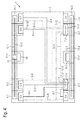
- Fig. 4 shows a block diagram of another exemplary embodiment of an electronics installation system 1 according to the present invention.
- the electronics installation system 1 of Fig. 4 is based on the electronics installation system 1 of Fig. 1 .
- the electronics installation system 1 of Fig. 4 comprises electronic modules 5-4 - 5-n installed in the installation slots 4-1 - 4-n. Furthermore, the electronics installation system 1 comprises two wiring configuration slots 6-1, 6-2.
- the first wiring configuration slot 6-1 is provided in the second slot in the lower left corner of the mechanical installation structure 3 and the second wiring configuration slot 6-2 is provided in the first slot in the lower right corner of the mechanical installation structure 3.
- the interconnection matrix 8 (not explicitly indicated) of Fig. 4 comprises further data connections 9-8 - 9-13, which connect every installation slot 4-1- 4-n to the second wiring configuration slot 6-2. Furthermore a data connection 9-14 interconnects the wiring configuration slots 6-1, 6-2.
- a first wiring configuration module 7-1 and a second wiring configuration module 7-2 are provided, respectively, which interconnect specific data connections 9-1 - 9-14.
- the electronic modules 5-1- 5-n and the wiring configuration modules 7-1, 7-2 shown in Fig. 4 are just exemplary. It should be understood that specific slots in the mechanical installation structure 3 can be left unequipped and reserved for future upgrading.
- the first wiring configuration module 7-1 comprises internal interconnection paths 17-1 and 17-2.
- Internal interconnection path 17-1 interconnects data connections 9-7, 9-2 and 9-4.
- Internal interconnection path 17- 2 interconnects data connections 9-1, 9-3 and 9-14.
- the second wiring configuration module 7-2 comprises internal interconnection path 17-3, which interconnects data connections 9-14, and 9-13.
- the data connections 9-8 - 9-11 are routed to the wiring configuration slot 6-2 even though they are not connected to any other data connection 9-1- 9-14 by the second wiring configuration module 7-2. But in case the electronic modules 5-1- 5-n are updated or modified or in case new electronic modules are added to the electronic installation system 1 data connections can easily be provided by amending the first and second wiring configuration modules 7-1, 7-2.
- more than two wiring configuration modules 7-1, 7-2 can be provided.
- fully redundant network topologies can be provided by providing two wiring configuration modules 7-1, 7-2 for each network.
- one wiring configuration module 7-1, 7-2 can connect multiple electronic modules 5-1- 5-n in different networks, as shown with wiring configuration module 7-1.
- the mechanical installation structure 3 comprises two power supply slots 12-1, 12-2.
- the first power supply slot 12-1 is provided just as an example in the upper row of slots in the mechanical installation structure 3.
- the second power supply slot 12-2 is provided in the lower row of slots in the mechanical installation structure 3.
- a power supply unit 16-1, 16-2 is installed, respectively. Furthermore, a power bus 14-1, 14-2 comprising two power lines 13-1, 13-2 and 13-3, 13-4 connects the slots 12-1, 12-2 of the respective rows to the respective power supply units 16-1, 16-2.
- the power bus 14-1 furthermore comprises a protection unit 15 which protects the bus, e.g. from voltage drops or over voltages, in case of a failure of any module connected to the power bus 14-1.
- the protection unit 15 is just exemplarily shown in the power supply slot 12-1. In another embodiment the protection unit 15 can be provided as several protection units 15, e.g. one protection unit 15 for each slot.
- single power supply lines can be provided between the power supply slots 12-1, 12-2 and the installation slots 4-1 - 4-n or the wiring configuration slots 6-1 - 6-n.
Landscapes
- Engineering & Computer Science (AREA)
- Microelectronics & Electronic Packaging (AREA)
- Computer Networks & Wireless Communication (AREA)
- Power Engineering (AREA)
- Mechanical Engineering (AREA)
- Connection Or Junction Boxes (AREA)
- Physics & Mathematics (AREA)
- General Physics & Mathematics (AREA)
- Optics & Photonics (AREA)
Priority Applications (2)
| Application Number | Priority Date | Filing Date | Title |
|---|---|---|---|
| EP14194271.4A EP3024309B1 (fr) | 2014-11-21 | 2014-11-21 | Système d'installation électronique, aéronef ou engin spatial et procédé |
| US14/946,310 US10457231B2 (en) | 2014-11-21 | 2015-11-19 | Electronics installation system, aircraft or spacecraft, and method |
Applications Claiming Priority (1)
| Application Number | Priority Date | Filing Date | Title |
|---|---|---|---|
| EP14194271.4A EP3024309B1 (fr) | 2014-11-21 | 2014-11-21 | Système d'installation électronique, aéronef ou engin spatial et procédé |
Publications (2)
| Publication Number | Publication Date |
|---|---|
| EP3024309A1 true EP3024309A1 (fr) | 2016-05-25 |
| EP3024309B1 EP3024309B1 (fr) | 2018-02-28 |
Family
ID=52013823
Family Applications (1)
| Application Number | Title | Priority Date | Filing Date |
|---|---|---|---|
| EP14194271.4A Active EP3024309B1 (fr) | 2014-11-21 | 2014-11-21 | Système d'installation électronique, aéronef ou engin spatial et procédé |
Country Status (2)
| Country | Link |
|---|---|
| US (1) | US10457231B2 (fr) |
| EP (1) | EP3024309B1 (fr) |
Cited By (2)
| Publication number | Priority date | Publication date | Assignee | Title |
|---|---|---|---|---|
| WO2018060389A1 (fr) * | 2016-09-30 | 2018-04-05 | Safran Electronics & Defense | Unite electronique a modules inversables |
| WO2020249258A1 (fr) * | 2019-06-11 | 2020-12-17 | Latelec | Baie avionique d'aeronef a plateau d'interconnexion |
Families Citing this family (2)
| Publication number | Priority date | Publication date | Assignee | Title |
|---|---|---|---|---|
| DE102016121598A1 (de) * | 2016-11-10 | 2018-05-17 | Airbus Operations Gmbh | Basismodul und Luftfahrtcomputersystem mit dem Basismodul |
| US11132033B2 (en) * | 2019-01-16 | 2021-09-28 | Hamilton Sundstrand Corporation | Modular controllers |
Citations (3)
| Publication number | Priority date | Publication date | Assignee | Title |
|---|---|---|---|---|
| US20030016520A1 (en) * | 2001-07-23 | 2003-01-23 | Cooney Robert C. | Serviceable power modules for a power distribution assembly |
| FR2927222A1 (fr) * | 2008-02-05 | 2009-08-07 | Thales Sa | Arrangement de rack avionique |
| FR2977447A1 (fr) * | 2011-07-01 | 2013-01-04 | Airbus Operations Sas | Cabinet electronique a connexion laterale |
Family Cites Families (4)
| Publication number | Priority date | Publication date | Assignee | Title |
|---|---|---|---|---|
| US5130893A (en) * | 1990-01-17 | 1992-07-14 | Square D Company | Signal distribution system |
| US8107256B1 (en) * | 2007-10-26 | 2012-01-31 | Solace Systems, Inc. | Serviceable networking appliance chassis |
| DE112010005798T5 (de) * | 2010-09-15 | 2013-05-16 | Hewlett-Packard Development Co., L.P. | Computersystem mit Fabric-Modulen |
| US20120203401A1 (en) * | 2011-02-08 | 2012-08-09 | Jonathan Mark Dunsdon | Onboard Maintenance System Network Optimization |
-
2014
- 2014-11-21 EP EP14194271.4A patent/EP3024309B1/fr active Active
-
2015
- 2015-11-19 US US14/946,310 patent/US10457231B2/en not_active Expired - Fee Related
Patent Citations (3)
| Publication number | Priority date | Publication date | Assignee | Title |
|---|---|---|---|---|
| US20030016520A1 (en) * | 2001-07-23 | 2003-01-23 | Cooney Robert C. | Serviceable power modules for a power distribution assembly |
| FR2927222A1 (fr) * | 2008-02-05 | 2009-08-07 | Thales Sa | Arrangement de rack avionique |
| FR2977447A1 (fr) * | 2011-07-01 | 2013-01-04 | Airbus Operations Sas | Cabinet electronique a connexion laterale |
Cited By (8)
| Publication number | Priority date | Publication date | Assignee | Title |
|---|---|---|---|---|
| WO2018060389A1 (fr) * | 2016-09-30 | 2018-04-05 | Safran Electronics & Defense | Unite electronique a modules inversables |
| FR3057112A1 (fr) * | 2016-09-30 | 2018-04-06 | Safran Electronics & Defense | Unite electronique a modules inversables |
| CN109792852A (zh) * | 2016-09-30 | 2019-05-21 | 赛峰电子与防务公司 | 具有可逆模块的电子单元 |
| US10709030B2 (en) | 2016-09-30 | 2020-07-07 | Safran Electronics & Defense | Electronic unit with reversible modules |
| CN109792852B (zh) * | 2016-09-30 | 2020-09-25 | 赛峰电子与防务公司 | 具有可逆模块的电子单元 |
| WO2020249258A1 (fr) * | 2019-06-11 | 2020-12-17 | Latelec | Baie avionique d'aeronef a plateau d'interconnexion |
| FR3097403A1 (fr) * | 2019-06-11 | 2020-12-18 | Latelec | Baie avionique d’aéronef à plateau d’interconnexion |
| US11924991B2 (en) | 2019-06-11 | 2024-03-05 | Latelec | Aircraft avionics rack with interconnection platform |
Also Published As
| Publication number | Publication date |
|---|---|
| US10457231B2 (en) | 2019-10-29 |
| EP3024309B1 (fr) | 2018-02-28 |
| US20160229361A1 (en) | 2016-08-11 |
Similar Documents
| Publication | Publication Date | Title |
|---|---|---|
| US8035985B2 (en) | Avionics rack arrangement | |
| US8369069B2 (en) | Avionics equipment carrier system with quick-mount housing and quick-mount modules | |
| US8559183B1 (en) | Method to use empty slots in onboard aircraft servers and communication devices to install non-proprietary servers and communications interfaces | |
| EP3024309B1 (fr) | Système d'installation électronique, aéronef ou engin spatial et procédé | |
| US7352946B2 (en) | Fiber sub-system for a shelf | |
| US9791644B2 (en) | Data bus-in-a-box (BiB) system design and implementation | |
| US8382516B2 (en) | Adaptable configuration plug in a vehicle entertainment system | |
| US6554639B2 (en) | Wiring interface | |
| CA2912960A1 (fr) | Reconfiguration de systeme de test automatise a grande echelle | |
| US9877087B2 (en) | Telephony equipment migration | |
| US20140117154A1 (en) | Rotorcraft fitted with a mounting structure for jointly mounting a control panel and an avionics rack previously fitted with a unitary cabling assembly | |
| EP2222032A1 (fr) | Utilisation de commutateur pour router des bus de données d'avion à base d'ethernet dans des systèmes avioniques | |
| JP6059658B2 (ja) | マルチインターフェース | |
| US11997818B2 (en) | Interconnection system for a rack of a system of an aircraft | |
| EP3684149B1 (fr) | Contrôleurs modulaires | |
| US20140086261A1 (en) | System architecture and method for communication between devices over backplane to reduce interface count | |
| WO2017217482A1 (fr) | Système de commande | |
| EP0903827A1 (fr) | Interface de câblage | |
| US20010041473A1 (en) | Wiring interface | |
| CN112193436A (zh) | 民用客机客舱系统集成验证测试环境系统 | |
| CA2214808A1 (fr) | Interface de cablage |
Legal Events
| Date | Code | Title | Description |
|---|---|---|---|
| AK | Designated contracting states |
Kind code of ref document: A1 Designated state(s): AL AT BE BG CH CY CZ DE DK EE ES FI FR GB GR HR HU IE IS IT LI LT LU LV MC MK MT NL NO PL PT RO RS SE SI SK SM TR |
|
| AX | Request for extension of the european patent |
Extension state: BA ME |
|
| PUAI | Public reference made under article 153(3) epc to a published international application that has entered the european phase |
Free format text: ORIGINAL CODE: 0009012 |
|
| STAA | Information on the status of an ep patent application or granted ep patent |
Free format text: STATUS: REQUEST FOR EXAMINATION WAS MADE |
|
| 17P | Request for examination filed |
Effective date: 20161124 |
|
| RBV | Designated contracting states (corrected) |
Designated state(s): AL AT BE BG CH CY CZ DE DK EE ES FI FR GB GR HR HU IE IS IT LI LT LU LV MC MK MT NL NO PL PT RO RS SE SI SK SM TR |
|
| GRAP | Despatch of communication of intention to grant a patent |
Free format text: ORIGINAL CODE: EPIDOSNIGR1 |
|
| STAA | Information on the status of an ep patent application or granted ep patent |
Free format text: STATUS: GRANT OF PATENT IS INTENDED |
|
| INTG | Intention to grant announced |
Effective date: 20170929 |
|
| GRAS | Grant fee paid |
Free format text: ORIGINAL CODE: EPIDOSNIGR3 |
|
| GRAA | (expected) grant |
Free format text: ORIGINAL CODE: 0009210 |
|
| STAA | Information on the status of an ep patent application or granted ep patent |
Free format text: STATUS: THE PATENT HAS BEEN GRANTED |
|
| AK | Designated contracting states |
Kind code of ref document: B1 Designated state(s): AL AT BE BG CH CY CZ DE DK EE ES FI FR GB GR HR HU IE IS IT LI LT LU LV MC MK MT NL NO PL PT RO RS SE SI SK SM TR |
|
| REG | Reference to a national code |
Ref country code: GB Ref legal event code: FG4D Ref country code: CH Ref legal event code: EP |
|
| REG | Reference to a national code |
Ref country code: AT Ref legal event code: REF Ref document number: 975507 Country of ref document: AT Kind code of ref document: T Effective date: 20180315 |
|
| REG | Reference to a national code |
Ref country code: IE Ref legal event code: FG4D |
|
| REG | Reference to a national code |
Ref country code: DE Ref legal event code: R096 Ref document number: 602014021556 Country of ref document: DE |
|
| REG | Reference to a national code |
Ref country code: NL Ref legal event code: MP Effective date: 20180228 |
|
| REG | Reference to a national code |
Ref country code: LT Ref legal event code: MG4D |
|
| REG | Reference to a national code |
Ref country code: AT Ref legal event code: MK05 Ref document number: 975507 Country of ref document: AT Kind code of ref document: T Effective date: 20180228 |
|
| PG25 | Lapsed in a contracting state [announced via postgrant information from national office to epo] |
Ref country code: FI Free format text: LAPSE BECAUSE OF FAILURE TO SUBMIT A TRANSLATION OF THE DESCRIPTION OR TO PAY THE FEE WITHIN THE PRESCRIBED TIME-LIMIT Effective date: 20180228 Ref country code: NO Free format text: LAPSE BECAUSE OF FAILURE TO SUBMIT A TRANSLATION OF THE DESCRIPTION OR TO PAY THE FEE WITHIN THE PRESCRIBED TIME-LIMIT Effective date: 20180528 Ref country code: LT Free format text: LAPSE BECAUSE OF FAILURE TO SUBMIT A TRANSLATION OF THE DESCRIPTION OR TO PAY THE FEE WITHIN THE PRESCRIBED TIME-LIMIT Effective date: 20180228 Ref country code: NL Free format text: LAPSE BECAUSE OF FAILURE TO SUBMIT A TRANSLATION OF THE DESCRIPTION OR TO PAY THE FEE WITHIN THE PRESCRIBED TIME-LIMIT Effective date: 20180228 Ref country code: HR Free format text: LAPSE BECAUSE OF FAILURE TO SUBMIT A TRANSLATION OF THE DESCRIPTION OR TO PAY THE FEE WITHIN THE PRESCRIBED TIME-LIMIT Effective date: 20180228 Ref country code: ES Free format text: LAPSE BECAUSE OF FAILURE TO SUBMIT A TRANSLATION OF THE DESCRIPTION OR TO PAY THE FEE WITHIN THE PRESCRIBED TIME-LIMIT Effective date: 20180228 Ref country code: CY Free format text: LAPSE BECAUSE OF FAILURE TO SUBMIT A TRANSLATION OF THE DESCRIPTION OR TO PAY THE FEE WITHIN THE PRESCRIBED TIME-LIMIT Effective date: 20180228 |
|
| PG25 | Lapsed in a contracting state [announced via postgrant information from national office to epo] |
Ref country code: GR Free format text: LAPSE BECAUSE OF FAILURE TO SUBMIT A TRANSLATION OF THE DESCRIPTION OR TO PAY THE FEE WITHIN THE PRESCRIBED TIME-LIMIT Effective date: 20180529 Ref country code: LV Free format text: LAPSE BECAUSE OF FAILURE TO SUBMIT A TRANSLATION OF THE DESCRIPTION OR TO PAY THE FEE WITHIN THE PRESCRIBED TIME-LIMIT Effective date: 20180228 Ref country code: SE Free format text: LAPSE BECAUSE OF FAILURE TO SUBMIT A TRANSLATION OF THE DESCRIPTION OR TO PAY THE FEE WITHIN THE PRESCRIBED TIME-LIMIT Effective date: 20180228 Ref country code: AT Free format text: LAPSE BECAUSE OF FAILURE TO SUBMIT A TRANSLATION OF THE DESCRIPTION OR TO PAY THE FEE WITHIN THE PRESCRIBED TIME-LIMIT Effective date: 20180228 Ref country code: BG Free format text: LAPSE BECAUSE OF FAILURE TO SUBMIT A TRANSLATION OF THE DESCRIPTION OR TO PAY THE FEE WITHIN THE PRESCRIBED TIME-LIMIT Effective date: 20180528 Ref country code: RS Free format text: LAPSE BECAUSE OF FAILURE TO SUBMIT A TRANSLATION OF THE DESCRIPTION OR TO PAY THE FEE WITHIN THE PRESCRIBED TIME-LIMIT Effective date: 20180228 |
|
| PG25 | Lapsed in a contracting state [announced via postgrant information from national office to epo] |
Ref country code: PL Free format text: LAPSE BECAUSE OF FAILURE TO SUBMIT A TRANSLATION OF THE DESCRIPTION OR TO PAY THE FEE WITHIN THE PRESCRIBED TIME-LIMIT Effective date: 20180228 Ref country code: EE Free format text: LAPSE BECAUSE OF FAILURE TO SUBMIT A TRANSLATION OF THE DESCRIPTION OR TO PAY THE FEE WITHIN THE PRESCRIBED TIME-LIMIT Effective date: 20180228 Ref country code: AL Free format text: LAPSE BECAUSE OF FAILURE TO SUBMIT A TRANSLATION OF THE DESCRIPTION OR TO PAY THE FEE WITHIN THE PRESCRIBED TIME-LIMIT Effective date: 20180228 Ref country code: IT Free format text: LAPSE BECAUSE OF FAILURE TO SUBMIT A TRANSLATION OF THE DESCRIPTION OR TO PAY THE FEE WITHIN THE PRESCRIBED TIME-LIMIT Effective date: 20180228 Ref country code: RO Free format text: LAPSE BECAUSE OF FAILURE TO SUBMIT A TRANSLATION OF THE DESCRIPTION OR TO PAY THE FEE WITHIN THE PRESCRIBED TIME-LIMIT Effective date: 20180228 |
|
| REG | Reference to a national code |
Ref country code: DE Ref legal event code: R097 Ref document number: 602014021556 Country of ref document: DE |
|
| PG25 | Lapsed in a contracting state [announced via postgrant information from national office to epo] |
Ref country code: CZ Free format text: LAPSE BECAUSE OF FAILURE TO SUBMIT A TRANSLATION OF THE DESCRIPTION OR TO PAY THE FEE WITHIN THE PRESCRIBED TIME-LIMIT Effective date: 20180228 Ref country code: DK Free format text: LAPSE BECAUSE OF FAILURE TO SUBMIT A TRANSLATION OF THE DESCRIPTION OR TO PAY THE FEE WITHIN THE PRESCRIBED TIME-LIMIT Effective date: 20180228 Ref country code: SM Free format text: LAPSE BECAUSE OF FAILURE TO SUBMIT A TRANSLATION OF THE DESCRIPTION OR TO PAY THE FEE WITHIN THE PRESCRIBED TIME-LIMIT Effective date: 20180228 Ref country code: SK Free format text: LAPSE BECAUSE OF FAILURE TO SUBMIT A TRANSLATION OF THE DESCRIPTION OR TO PAY THE FEE WITHIN THE PRESCRIBED TIME-LIMIT Effective date: 20180228 |
|
| PLBE | No opposition filed within time limit |
Free format text: ORIGINAL CODE: 0009261 |
|
| STAA | Information on the status of an ep patent application or granted ep patent |
Free format text: STATUS: NO OPPOSITION FILED WITHIN TIME LIMIT |
|
| 26N | No opposition filed |
Effective date: 20181129 |
|
| PG25 | Lapsed in a contracting state [announced via postgrant information from national office to epo] |
Ref country code: SI Free format text: LAPSE BECAUSE OF FAILURE TO SUBMIT A TRANSLATION OF THE DESCRIPTION OR TO PAY THE FEE WITHIN THE PRESCRIBED TIME-LIMIT Effective date: 20180228 |
|
| REG | Reference to a national code |
Ref country code: CH Ref legal event code: PL |
|
| PG25 | Lapsed in a contracting state [announced via postgrant information from national office to epo] |
Ref country code: MC Free format text: LAPSE BECAUSE OF FAILURE TO SUBMIT A TRANSLATION OF THE DESCRIPTION OR TO PAY THE FEE WITHIN THE PRESCRIBED TIME-LIMIT Effective date: 20180228 Ref country code: LU Free format text: LAPSE BECAUSE OF NON-PAYMENT OF DUE FEES Effective date: 20181121 |
|
| REG | Reference to a national code |
Ref country code: BE Ref legal event code: MM Effective date: 20181130 |
|
| REG | Reference to a national code |
Ref country code: IE Ref legal event code: MM4A |
|
| PG25 | Lapsed in a contracting state [announced via postgrant information from national office to epo] |
Ref country code: CH Free format text: LAPSE BECAUSE OF NON-PAYMENT OF DUE FEES Effective date: 20181130 Ref country code: LI Free format text: LAPSE BECAUSE OF NON-PAYMENT OF DUE FEES Effective date: 20181130 |
|
| PG25 | Lapsed in a contracting state [announced via postgrant information from national office to epo] |
Ref country code: IE Free format text: LAPSE BECAUSE OF NON-PAYMENT OF DUE FEES Effective date: 20181121 |
|
| PG25 | Lapsed in a contracting state [announced via postgrant information from national office to epo] |
Ref country code: BE Free format text: LAPSE BECAUSE OF NON-PAYMENT OF DUE FEES Effective date: 20181130 |
|
| PG25 | Lapsed in a contracting state [announced via postgrant information from national office to epo] |
Ref country code: MT Free format text: LAPSE BECAUSE OF NON-PAYMENT OF DUE FEES Effective date: 20181121 |
|
| PG25 | Lapsed in a contracting state [announced via postgrant information from national office to epo] |
Ref country code: TR Free format text: LAPSE BECAUSE OF FAILURE TO SUBMIT A TRANSLATION OF THE DESCRIPTION OR TO PAY THE FEE WITHIN THE PRESCRIBED TIME-LIMIT Effective date: 20180228 |
|
| PG25 | Lapsed in a contracting state [announced via postgrant information from national office to epo] |
Ref country code: PT Free format text: LAPSE BECAUSE OF FAILURE TO SUBMIT A TRANSLATION OF THE DESCRIPTION OR TO PAY THE FEE WITHIN THE PRESCRIBED TIME-LIMIT Effective date: 20180228 |
|
| PG25 | Lapsed in a contracting state [announced via postgrant information from national office to epo] |
Ref country code: HU Free format text: LAPSE BECAUSE OF FAILURE TO SUBMIT A TRANSLATION OF THE DESCRIPTION OR TO PAY THE FEE WITHIN THE PRESCRIBED TIME-LIMIT; INVALID AB INITIO Effective date: 20141121 Ref country code: MK Free format text: LAPSE BECAUSE OF NON-PAYMENT OF DUE FEES Effective date: 20180228 |
|
| PG25 | Lapsed in a contracting state [announced via postgrant information from national office to epo] |
Ref country code: IS Free format text: LAPSE BECAUSE OF FAILURE TO SUBMIT A TRANSLATION OF THE DESCRIPTION OR TO PAY THE FEE WITHIN THE PRESCRIBED TIME-LIMIT Effective date: 20180628 |
|
| PGFP | Annual fee paid to national office [announced via postgrant information from national office to epo] |
Ref country code: GB Payment date: 20211119 Year of fee payment: 8 |
|
| GBPC | Gb: european patent ceased through non-payment of renewal fee |
Effective date: 20221121 |
|
| PG25 | Lapsed in a contracting state [announced via postgrant information from national office to epo] |
Ref country code: GB Free format text: LAPSE BECAUSE OF NON-PAYMENT OF DUE FEES Effective date: 20221121 |
|
| PGFP | Annual fee paid to national office [announced via postgrant information from national office to epo] |
Ref country code: DE Payment date: 20251119 Year of fee payment: 12 |
|
| PGFP | Annual fee paid to national office [announced via postgrant information from national office to epo] |
Ref country code: FR Payment date: 20251125 Year of fee payment: 12 |