EP3024313B1 - Lame circulaire ondulée avec des encoches - Google Patents
Lame circulaire ondulée avec des encoches Download PDFInfo
- Publication number
- EP3024313B1 EP3024313B1 EP14829230.3A EP14829230A EP3024313B1 EP 3024313 B1 EP3024313 B1 EP 3024313B1 EP 14829230 A EP14829230 A EP 14829230A EP 3024313 B1 EP3024313 B1 EP 3024313B1
- Authority
- EP
- European Patent Office
- Prior art keywords
- disc blade
- wavy
- engagement surface
- tooth
- beveled
- Prior art date
- Legal status (The legal status is an assumption and is not a legal conclusion. Google has not performed a legal analysis and makes no representation as to the accuracy of the status listed.)
- Active
Links
Images



Classifications
-
- A—HUMAN NECESSITIES
- A01—AGRICULTURE; FORESTRY; ANIMAL HUSBANDRY; HUNTING; TRAPPING; FISHING
- A01B—SOIL WORKING IN AGRICULTURE OR FORESTRY; PARTS, DETAILS, OR ACCESSORIES OF AGRICULTURAL MACHINES OR IMPLEMENTS, IN GENERAL
- A01B7/00—Disc-like soil-working implements usable either as ploughs or as harrows, or the like
-
- A—HUMAN NECESSITIES
- A01—AGRICULTURE; FORESTRY; ANIMAL HUSBANDRY; HUNTING; TRAPPING; FISHING
- A01B—SOIL WORKING IN AGRICULTURE OR FORESTRY; PARTS, DETAILS, OR ACCESSORIES OF AGRICULTURAL MACHINES OR IMPLEMENTS, IN GENERAL
- A01B15/00—Elements, tools, or details of ploughs
- A01B15/16—Discs; Scrapers for cleaning discs; Sharpening attachments
-
- A—HUMAN NECESSITIES
- A01—AGRICULTURE; FORESTRY; ANIMAL HUSBANDRY; HUNTING; TRAPPING; FISHING
- A01B—SOIL WORKING IN AGRICULTURE OR FORESTRY; PARTS, DETAILS, OR ACCESSORIES OF AGRICULTURAL MACHINES OR IMPLEMENTS, IN GENERAL
- A01B21/00—Harrows with rotary non-driven tools
- A01B21/08—Harrows with rotary non-driven tools with disc-like tools
-
- A—HUMAN NECESSITIES
- A01—AGRICULTURE; FORESTRY; ANIMAL HUSBANDRY; HUNTING; TRAPPING; FISHING
- A01B—SOIL WORKING IN AGRICULTURE OR FORESTRY; PARTS, DETAILS, OR ACCESSORIES OF AGRICULTURAL MACHINES OR IMPLEMENTS, IN GENERAL
- A01B23/00—Elements, tools, or details of harrows
- A01B23/06—Discs; Scrapers for cleaning discs; Sharpening attachments
Definitions
- the present invention relates generally to agricultural equipment, and more particularly to a disc blade for tilling soil.
- the disc blade of the present invention may be used with harrows or similar equipment and is suitable, for example, in vertical tillage applications.
- Disc blades have been used in the agricultural industry to work soil, i.e., leveling, breaking up, burying residue, etc.
- Disc blades may typically be attached to, or operate as part of, devices such as a harrow or similar agricultural implements.
- the disc blades are pulled through the soil while being caused to rotate.
- the rotating blade engages the soil as it passes through the soil, thereby working the soil. This may be done, for example, in preparation for planting and/or for seasonal soil maintenance.
- Prior art disc blades have been made in numerous configurations. However, nearly all such prior art blades typically have a generally round (disc-like) shape with either a generally flat or a generally concave central portion configured with a hole or other opening, or openings, configured to mount the blade to a harrow or similar agricultural implement. Many of the other features of such blades can vary depending on the nature of the particular tilling application and the characteristics of the soil being tilled, such as the hardness of the soil, the presence of rocks or other content, and/or the presence of certain types of agricultural residue.
- some prior art blades have a generally smooth surface.
- other blades have been formed with surface deformations, such as flutes, ridges, grooves, scallops, waves and the like that are designed to cut and move the soil in a manner that results in the desired soil condition.
- some other prior art disc blades include a generally circular edge (or perimeter or periphery), while other disc blades incorporate various edge geometries and/or deformations, such as notches, grooves, bevels, teeth, sawteeth and like structures that are adapted to address various types of soils and tilling conditions.
- Prior art disc blades have been made in various diameters, ranging from diameters of about 8 inches to diameters of about 36 inches, depending on the geometry and configuration of the particular blade, the nature of the particular tilling application and the characteristics of the soil being tilled.
- prior art disc blades have been made either as flat disc blades (having essentially zero concavity), shallow concavity blades (having radii of curvature in the range of about 850-1000 mm) or as high concavity disc blades (having radii of curvature in the range of about 600-750 mm).
- the radius of curvature of the disc blade refers to degree of curvature of the curved portion of the disc blade.
- One particular disc blade that has been developed in the art is a disc blade with a radially toothed cutting edge or outer periphery, i.e., the edge comprises teeth having a generally radially sinusoidal, or wavy, geometry.
- This prior art disc blade includes a generally circular plate having a peripheral radially toothed cutting edge, a smooth (i.e., non-fluted, non-wavy) central portion configured to mountingly engage a harrow or like agricultural implement, and a wavy (or fluted) portion having a plurality of waves or flutes formed by a plurality of adjacent crests and valleys disposed between the smooth central portion and the radially toothed edge.
- the plurality of crests extend radially from the central portion of the disc blade at a distance that is further than the distance that the plurality of valleys.
- a radially toothed cutting edge is formed along the outer periphery of the blade.
- the geometry of this radially toothed edge may provide for improved soil and residue cutting performance while at the same time providing the disc blade with the ability to self-sharpen with ongoing use.
- the toothed cutting edge includes a plurality of teeth that are symmetrically formed.
- the structure of the disc blade provides that the crests and valleys will wear generally evenly, maintaining the radially toothed profile of the outer periphery of the disc blade instead of wearing unevenly and creating a generally smooth outer periphery over a period of extended use.
- the edge of the disc blade will generally maintain its radially toothed profile instead of becoming smooth (non-toothed), as has been the case with other prior art disc blade designs.
- the number and depth of the waves may vary depending on the diameter of the disc blade, the nature of the particular tilling application and the characteristics of the soil being tilled (such as the hardness of the soil, the presence of rocks or other content, and/or the presence of certain types of agricultural residue).
- a common 20 inch blade may have 32 waves formed by the plurality of adjacent crests and valleys, and each wave may have a depth of between 6 and 9 mm (this distance from the top of one crest to the bottom of an adjacent valley).
- numerous variations in the number of waves and their depth are possible.
- vertical tillage involves the use of disc blades configured in a generally vertical orientation relative to the soil. That is, the blades are mounted such that the edge or outer periphery of the blade is perpendicular or transverse to the horizontal plane of the soil, such that the disc blades may cut vertically into the soil.
- the advantages of vertical tillage over horizontal tillage are well versed in the advantages of vertical tillage over horizontal tillage, however, one of the major advantages of vertical tillage is the ability to cut, size and bury residue.
- prior art disc blades designed for use in prior art horizontal tillage applications are not suitable for use in vertical tillage systems. That is, many such prior art disc blade designs would create undesirable side effects if used in vertical tillage applications, such as unacceptable soil throw. Additionally, many prior art disc blade designs do not have a sufficiently sharp edge for cutting, sizing and burying residue. Further still, symmetrically formed teeth formed along an edge of the disc blade may provide an inadequate tilling function.
- a new disc blade that is particularly suitable for use in vertical tillage applications.
- a disc blade comprises a wavy disc blade with a radially toothed edge or outer periphery configured to improved cutting, sizing and burying of residue.
- the present invention satisfies this need.
- US 7992651 discloses a wavy disc and coulter with notches and a method of use.
- the disc or coulter has a plurality of waves formed in the blade by deviating the entire outer periphery of the variable wave coulter from a flat plane.
- a plurality of crests and a plurality of valleys are formed in the blade, wherein each of said plurality of waves comprises a first and a second crest and one valley between the first and second crests at the outer periphery thereof.
- a notch is disposed in each respective wave on the outer periphery of the blade and wherein at least a majority of the notch is disposed between the first one of the respective crests and the respective valley, such majority of the notch being closer to the first respective crest than to the second respective crest.
- US 5346020 discloses a clearing wheel for agricultural residue.
- the wheel has a hub defining a central axis, about which the cleaning wheel can be rotated in use, and a plurality of cutting teeth projecting radially outwardly from the hub to intercept and resituate residue upon the clearing wheel's being rotated about its central axis.
- At least a first and second of the teeth have an internal grain pattern running in first and second transverse directions.
- '020 also discloses a method of making a clearing wheel by a forging process..
- a wavy disc blade having a first side, a second side, a central portion having at least one opening formed therein, and a wavy portion adjacent to, extending radially from and circumferentially about the central portion.
- the wavy portion includes a plurality of waves extending from the central portion to an edge portion, the waves forming a plurality of crests and valleys between the central portion and the edge portion.
- the disc blade further includes a plurality of cutting teeth formed along the edge portion, each tooth of the plurality cutting teeth having a first engagement surface and a second engagement surface, the first engagement surface being shorter than the second engagement surface so that each tooth is asymmetrically shaped.
- At least one of a first beveled portion may be formed on the first side at and along the edge portion and a second beveled portion may be formed on the second side at and along the edge portion.
- a wavy disc blade having a first side, a second side and a generally circular central portion having at least one opening formed therein.
- the disc blade also includes a wavy portion adjacent to, extending radially from and circumferentially about the central portion, the wavy portion having a plurality of waves extending from the central portion to an edge portion, the waves forming a plurality of crests and valleys between the central portion and the edge portion.
- a plurality of teeth and a plurality of notches are formed along the edge portion.
- Notches of the plurality of notches are alternately positioned between teeth of the plurality of teeth, and each notch of the plurality of notches has one of a first beveled portion formed on the first side of the disc blade or a second beveled portion formed on the second side of the disc blade.
- FIG. 1 illustrates a first side of wavy disc blade in accordance with an exemplary embodiment of the present invention.
- the wavy disc blade is shown generally at 10 and includes a first side 12.
- the first side 12 generally faces in a first axial direction.
- the wavy disc blade 10 also includes a central portion 14.
- the central portion 14 is generally circular. However, it is understood that the present description is not limited to this configuration. Additionally, the central portion 14 may be substantially planar, or alternatively, may be concave or convex.
- the central portion 14 has at least one opening 16 formed therein.
- the at least one opening 16 is a single opening positioned at or near a center of the central portion 14.
- the disc blade 10 is configured rotate on a rotation axis extending through the single opening.
- the rotation axis extends in the first axial direction and a second axial direction opposite to the first axial direction.
- the at least one opening 16 may include a plurality of openings positioned about the center of the central portion 14 through which the rotation axis extends.
- the at least one opening 16 is configured to receive a fastener or fasteners (not shown), a shaft, or an axle so as to rotatably secure the wavy disc blade 10 to an agricultural implement, such as a harrow (not shown).
- the at least one opening 16 may be non-circular in shape.
- the wavy disc blade 10 further includes a wavy portion 18.
- the wavy portion 18 is positioned adjacent to the central portion 14 and extends circumferentially around, and radially outward therefrom.
- the wavy portion 18 includes a plurality of waves 20 (or flutes or scallops) extending from the central portion 14 to an edge portion 22 of the disc blade 10.
- the edge portion 22 is formed at an outer radial edge of the disc blade 10.
- the plurality of waves 20 forms a plurality of crests 24 and a corresponding plurality of valleys 26.
- the crests 24 and valleys 26 are alternately positioned in a circumferential direction about the disc blade 10 and extend between the central portion 14 and the edge portion 22.
- the plurality of waves 20 may be curved in a circumferential direction as they extend radially outward from the central portion 14. Additionally, the wavy portion 18 may be substantially planar, or alternatively, may be concave or convex. In an exemplary embodiment, the disc blade 10 may have a diameter D of, for example, 16 inches to 24 inches, but is not limited thereto.
- the crests 24 project outward relative to the first side 12 of the central portion 14 generally in the first axial direction, while the valleys 26 do not extend beyond the first side 12 of the central portion 14 (see FIG. 4 ). It is understood, however, the present invention is not limited to this example, and other configurations are envisioned. For example, the crests 24 may project only to, or short of, the first side 12 at the central portion 14.
- a plurality of cutting teeth 28 are formed along the edge portion 22.
- Each tooth 28 of the plurality of cutting teeth includes a first engagement surface 30 and a second engagement surface 32 positioned circumferentially relative to first engagement surface 30 along the edge portion 22.
- the first engagement surface 30 is shorter than the second engagement surface 32.
- each tooth 28 is asymmetrically formed.
- the first engagement surface 30 may be a linear or curved segment.
- the second engagement surface 32 may also be a linear or curved segment.
- the first engagement surface 30 and second engagement surface 32 may intersect to form a peak on each tooth 28.
- the peak of a tooth 28 may be, for example, a point of the tooth 28 that is radially positioned farthest from the center point or rotation axis.
- one of the first engagement surface 30 and the second engagement surface 32 is configured to be a leading edge, in use, for engaging and penetrating a surface to be tilled, while the other of the first engagement surface 30 and the second engagement surface 32 is configured to be a trailing edge.
- each tooth 28 of the plurality of cutting teeth 28 may include a third engagement surface 34 positioned between the first engagement surface 30 and second engagement surface 32.
- peaks of the respective teeth 28 may be positioned at a point along the third engagement surface 34.
- the peaks may be positioned at an intersection the first engagement surface 30 and third engagement surface 34 or an intersection of the second engagement surface 32 and third engagement surface 34.
- the third engagement surface 34 may also be formed as a curved or linear segment.
- first engagement surface 30, second engagement surface 32 and third engagement surface 34 extend continuously to form a profile of each tooth 28.
- the plurality of teeth 28 form a profile of the edge portion 22.
- each tooth 28 may include more than one peak.
- a notch 36 is formed between adjacent teeth 28 of the plurality of cutting teeth.
- a plurality of notches 36 are formed about a periphery of the disc blade 10, with the notches 36 being alternately positioned with the teeth 28.
- each notch 36 is bound by a second engagement surface 32 of one tooth 28 and a first engagement surface 30 of a tooth 28 adjacent to the one tooth 28.
- a notch 36 may have width w1 of, for example, 60 mm to 64 mm.
- a notch 36 may have a depth d1 of between 15 mm to 25 mm, and in one embodiment, approximately 19 mm. It is understood, however, that these dimensions are provided as examples, and the present invention is not limited to these dimensions.
- the disc blade 10 may include twenty notches 36, but is not limited thereto.
- the individual teeth of the plurality of cutting teeth 28 may also include a first beveled portion 38.
- the first beveled portion 38 represents a section of reduced thickness of the teeth 28. In an exemplary embodiment, the thickness of a tooth reduces gradually when moving generally radially outward.
- the first beveled portion 38 may be angled relative to a plane in which the crests 24 of the waves lie. In one embodiment, the first beveled portion 38 is angled between an angle ⁇ 1 of, for example, 5 degrees to 30 degrees, as shown in FIG. 4 , and in one embodiment, 10 degrees. Alternatively, the angle ⁇ 1 may be formed at 15 degrees. However, the present invention is not limited to this particular configuration. Additionally, in one embodiment, the first beveled portion 38 extends from a portion of the tooth 28 to the edge portion 22 at the third engagement surface 34.
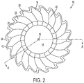
- FIG. 2 illustrates a second side 40, i.e., a rear view, of the wavy disc blade 10 according to an exemplary embodiment of the present invention.
- the second side 40 faces the second axial direction, opposite to the first axial direction and is positioned on a side of the disc blade 10 opposite to the first side 12.
- a thickness of the disc blade 10 is formed between the first side 12 and the second side 40.
- the wavy portion 18 extends along the second side 40.
- the plurality of valleys 26 of the waves 20 may extend beyond the central portion 14 at the second side 40 generally in the second axial direction.
- this configuration is only one example, and the present description is not limited thereto.
- the valleys 26 may extend only to the same extent of the central portion 14 at the second side 40, or to a lesser extent than the central portion 14 at the second side 14.
- the second side 40 may further include a second beveled portion 42 extending at the edge portion 22.
- the second beveled portion 42 is formed continuously about the periphery of the disc blade 10 on the second side 40. It is understood, however, that in some embodiments, the second bevel 42 may be formed discontinuously, or only along discrete segments of the edge portion 22.
- the second beveled portion 42 represents an area of decreased or decreasing thickness of the disc blade 10 along the teeth 28 and notches 36.
- the second beveled portion 42 may extend at an angle ⁇ 2 between, for example, 5 degrees to 30 degrees, and in one embodiment 20 degrees, relative to a plane in which the valleys 26 of the waves lie (see FIG. 4 ). It is understood, however, that the present invention is not limited to this configuration.
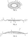
- FIG. 3 illustrates a perspective view showing the first side 12 of the wavy disc blade 10 according to an exemplary embodiment of the present invention.
- the crests 24 extend generally from the central portion 14 to distal ends of respective teeth 28.
- the valleys 26, positioned alternately with the crests 24, extend from the central portion 14 to respective notches 36.
- FIG. 4 illustrates a cross-sectional view of the wavy disc blade 10 according to an exemplary embodiment of the present invention.
- the cross-section is taken at A-A shown in FIG. 2 .
- the central portion 14 may be substantially planar. That is, the first side 12 and second side 40, in the area of the central portion 14 may each lie in separate, parallel planes spaced apart axially (in the direction of the first axial direction or second axial direction) by the thickness of the central portion 14.
- the crests 24 may lie in another plane and the valleys 26 may lie in yet another plane parallel to the plane in which the crests 24 lie. The planes are spaced apart by the height of the waves 20.
- the height h1 of the waves may be 14 mm - 17mm.
- the disc blade 10 may include waves having other suitable wave heights.
- the central portion 14 presents a substantially planar profile. It is understood, however, the present invention is not limited to this configuration, and other suitable configurations are envisioned.
- the wavy disc blade 10 may be formed as a substantially convex or concave unit, as described further below with reference to FIG. 5 .
- the crests 24 and valleys 26 on the first side 12 may be, on the second side 40, viewed as valleys and crests, respectively.
- the valleys i.e., the opposite side of the crests 24
- the crests i.e., the opposite side of the valleys 26
- FIG. 5 illustrates a cross-sectional view of the wavy disc blade 10 according to another exemplary embodiment of the present invention.
- the disc blade 10 is formed generally as a concave disc.
- the central portion 14 may be formed with a concavity, and thus, presents a concave profile on one side and a convex profile on the other side.
- the wavy portion 18 extends from the central portion 14 along a similar concave/convex profile.
- the first beveled portion 38 may extend at angle ⁇ 3 relative to a plane in which distal ends of the teeth 28 lie between 28 degrees and 32 degrees.
- the second beveled portion 42 may extend at an angle ⁇ 4 relative to the plane in which distal ends of the teeth lie between -2 degrees and 2 degrees.
- the first and second beveled portions may extend an angle similar to ⁇ 1 and ⁇ 2 described above.
- the wavy disc blade 10 may be a homogenous, integral unit.
- the wavy portion 18 and central portion 14 may be formed integrally.
- the central portion 14 and wavy portion 18 may be formed separately and joined together with a suitable fastener(s).
- the disc blade 10 may be rotated in either a first direction such that the first engagement surface 30 is configured to impact a work surface to be tilled, or a second direction such that the second engagement surface 32 is configured to impact a work surface, depending on a particular application and desired output from the disc blade 10.
- the geometry of the disc blade 10, including, for example, the asymmetric teeth 28, first beveled portion 38, second beveled portion 42 and the wavy portion 18 which presents a wave pattern of crests 24 and valleys 26 may improve ground penetration of the disc blade 10 along with residue cutting ability.
- the various engagement surfaces of teeth 28 and notches 36 are as described herein form sharp edges that improve residue cutting and sizing ability.
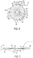
- FIGS. 6 and 7 illustrate a wavy disc blade 110 not part of the present invention.
- FIG. 6 is a front view illustrating a first side 112 of the wavy disc blade 110 according to an exemplary embodiment. Similar to the wavy disc blade 10 described in the exemplary embodiments above, the wavy disc blade 110 includes a central portion 114 having at least one opening 116 formed therein. The wavy disc blade 110 further includes a wavy portion 118 comprising a plurality of waves 120. The waves 120 extend radially outward from the central portion 114 to an edge portion 122. The waves 120 include a plurality of alternately positioned crests 124 and valleys 126.
- each tooth 128 may include a first engagement surface 130, a second engagement surface 132 and a third engagement surface 134. A peak of each tooth may be formed on the third engagement surface 134.
- Notches 136 are alternately formed between adjacent teeth 128.
- a notch is bounded by a first engagement surface 130 of a first tooth 128 and a second engagement surface 132 of a second tooth 128 adjacent to the first tooth 128.
- a notch 136 includes either a first beveled portion 138 formed on the first side 112 of the wavy disc blade 110 or a second beveled portion 142 formed on a second side 140 of the wavy disc blade 110, opposite to the first side 112.
- the teeth 128 may include beveled portions on the first side 112 and second side 140 of the wavy disc blade 110.
- the notches 136 include a first set of notches 144 and a second set of notches 146.
- the first set of notches 144 includes the first beveled portion 138 while the second set of notches 146 includes the second beveled portion 142.
- the notches of the first set of notches 144 and notches of the second set of notches 146 are alternately positioned.
- FIG. 7 illustrates a cross-section taken at B-B of FIG. 6 .
- the first beveled portion 138 may extend at an angle ⁇ 5 relative to a plane in which the wavy disc blade 110 lies of about 15 degrees.
- the second beveled portion may also extend at angle ⁇ 6 of about 15 degrees relative to a plane in which the wavy disc blade 110 lies.
- the plane in which the wavy disc blade 110 lies may be a plane that bisects a wave pattern formed by the wavy portion 118, through the diameter of the disc blade 110.
- the wavy disc blade 110 may include, for example, twenty six notches 136. More specifically, the disc blade 110 may include thirteen notches in the first set of notches 144 and thirteen notches in the second set of the notches 146.
- the notches 136 may have a depth d2 of, for example, about 22.9 mm (0.9 inches), and width w2 of, for example, about 59.2 mm (2.33 inches).
- the wave pattern of the wavy portion 118, measured from a crest 124 to a valley 126 may have a height h2 of, for example, 26.9 mm (1.06 inches). It is understood that these configurations are provided for the purposes of example, and variations in these dimensions are envisioned.
- ground penetration and cutting ability of the wavy disc blade 110 may be improved by, for example, the notches 136 having first and second beveled portions 138, 142.
- FIGS. 8 and 9 are partial views of a disc blade 210 according to another embodiment described herein.
- the disc blade 210 of FIGS. 8 and 9 may be formed in generally the same manner as the disc blade 10 described in the embodiment above with reference to FIGS. 1-4 . Accordingly, it is understood that further description of, or reference to the features described in the embodiments above may be omitted below. In addition, it is understood that features described in the embodiments above may be used together with features described in the embodiments below, and vice versa.
- FIG. 8 is a partial view of a first side 212 of the disc blade 210.
- FIG. 9 is a partial view of a second side 240 of the disc blade 210.
- the first beveled portion 238 may be discretely formed at each tooth 228 of the plurality of teeth.
- the first beveled portion 238 may extend from a radially inner portion of a tooth 228 to the first engagement surface 230, second engagement surface 232 and third engagement surface 234.
- the first beveled portion 238 extends at an angle ⁇ 1 (see FIG. 4 ) of about 5 degrees to 20 degrees, and in a specific embodiment, about 16 degrees, relative to a plane in which the crests 224 of the waves lie.
- a second beveled portion 242 may be formed similarly to the second beveled portion 42 described above with reference to FIGS. 1-4 . That is, the second beveled portion 242 may be formed continuously about the periphery of the disc blade 210 on the second side 240.
- the second beveled portion 242, in the region of the notches 236 may extend an angle ⁇ 2 (see FIG. 4 ) of about 5 degrees to 30 degrees, and in one embodiment, about 21 degrees.
- the second beveled portion 242 is formed differently in a region 243 at the peak of each tooth 228 than at a notch 236.
- the second beveled portion 242 may extend an angle ⁇ 2 (see FIG. 4 ) of about 5 degrees to 20 degrees, and in one embodiment, about 16 degrees.
- the notch 236 has a depth of approximately 15 mm to 25 mm.
- FIGS. 10 and 11 are partial views of a disc blade 310 according to another embodiment described herein.
- the disc blade 310 of FIGS. 10 and 11 may be formed in generally the same manner as the disc blade 10 described in the embodiment above with reference to FIGS. 1-4 . Accordingly, it is understood that further description of, or reference to the features described in the embodiments above may be omitted below. In addition, it is understood that features described in the embodiments above may be used together with features described in the embodiments below, and vice versa.
- FIG. 10 is a partial view of a first side 312 of the disc blade 310.
- FIG. 11 is a partial view of a second side 340 of the disc blade 310.
- the first beveled portion 338 may be continuously formed about the periphery of the disc blade 310, both at the teeth 328 and the notches 336.
- the first beveled portion 338 may extend from a radially inner portion of the wavy portion 318 to the first engagement surface 330, second engagement surface 332, third engagement surface 334 and notch 336.
- the first beveled portion 338 extends at an angle ⁇ 1 (see FIG. 4 ) of about 5 degrees to 40 degrees, and in a specific embodiment, about 11 degrees, relative to a plane in which the crests 324 of the waves lie.
- a second beveled portion 342 may be formed along the first engagement surface 330, second engagement surface 332 and the notch 336.
- the second beveled portion 342 may extend an angle ⁇ 2 (see FIG. 4 ) of about 10 degrees to 30 degrees, and in one embodiment, about 28 degrees.
- the tooth In a region at the peak of each tooth 328, i.e., at the third engagement surface 334, the tooth may be angled about 9 degrees.
- the notch may be formed having a depth of 15 mm - 25 mm, and in one embodiment, 19 mm.
- exemplary embodiments of the wavy disc blade disclosed herein may provide for several advantages of prior art disc blades, particularly for vertical tillage applications.
- one claimed advantage of vertical tillage is that vertical tillage devices can operate at shallower depths and at higher speeds than traditional tillage devices. At such shallower depths and higher speeds, the condition of the edge of the disc blade may restrict the disc blade's ability to cut and size residue. Therefore, a disc blade with a consistently sharp edge, as provided by the claimed disc blades, is advantageous for vertical tillage applications.
- the claimed disc blades may also provide several additional advantages over prior art disc blades.
- Third, the waves (or flutes or scallops) impart strength to the notches such that the notches are able to better withstand impacts with hard objects, such as rocks.
- the notches retain the ability to cut residue, as noted above, thereby reducing the need to add weight to the tilling device (as is known in the prior art to cause prior art disc blades to engage with the soil as they wear).
Landscapes
- Life Sciences & Earth Sciences (AREA)
- Engineering & Computer Science (AREA)
- Mechanical Engineering (AREA)
- Soil Sciences (AREA)
- Environmental Sciences (AREA)
- Structures Of Non-Positive Displacement Pumps (AREA)
- Polishing Bodies And Polishing Tools (AREA)
- Knives (AREA)
- Packaging Of Annular Or Rod-Shaped Articles, Wearing Apparel, Cassettes, Or The Like (AREA)
- Food-Manufacturing Devices (AREA)
Claims (13)
- Lame circulaire (10) ondulée, comprenant :un premier côté (12) ;un second côté (40) ;une partie centrale (14) dans laquelle est pratiquée au moins une ouverture (16) ;une partie ondulée (18) adjacente à la partie centrale, s'étendant radialement à partir de celle-ci et circonférentiellement autour d'elle, la partie ondulée (18) comportant une pluralité d'ondulations (20) s'étendant de la partie centrale (14) à une partie de bord (22), les ondulations (20) formant une pluralité de crêtes (24) et de vallées (26) entre la partie centrale (14) et la partie de bord (22) ;une pluralité de dents coupantes (28) formées le long de la partie de bord (22), chaque dent (28) de la pluralité de dents coupantes ayant une première surface (30) d'entrée en contact et une deuxième surface (32) d'entrée en contact, la première surface (30) d'entrée en contact étant plus courte que la deuxième surface (32) d'entrée en contact si bien que chaque dent (28) est de forme asymétrique ; etune première partie biseautée (38) sur le premier côté au niveau de la partie de bord (22) et/ou une seconde partie biseautée (42) sur le second côté (40) au niveau de la partie de bord (22).
- Lame circulaire ondulée selon la revendication 1, dans laquelle une encoche (36) est constituée entre des dents adjacentes (28) de la pluralité de dents coupantes (28) et l'encoche (36) est limitée par la deuxième surface (32) d'entrée en contact d'une dent et la première surface (30) d'entrée en contact d'une dent adjacente.
- Lame circulaire ondulée selon la revendication 2, dans laquelle chaque dent (28) de la pluralité de dents coupantes comprend une troisième surface (34) d'entrée en contact placée entre la première surface d'entrée en contact (30) et la deuxième surface d'entrée en contact (32) et le sommet de chaque dent (28) est formé le long de la troisième surface (34) d'entrée en contact.
- Lame circulaire ondulée selon la revendication 3, dans laquelle sur le premier côté (12), chaque crête (24) de la pluralité de crêtes s'étend jusqu'au sommet de dents (28) respectives de la pluralité de dents coupantes et chaque vallée (26) s'étend jusqu'à une encoche (36) correspondante.
- Lame circulaire ondulée selon la revendication 4, dans laquelle la première partie biseautée (38) est constituée par une partie de chaque dent (28) de la pluralité de dents sur le premier côté (12) en biais vers le second côté (40) de telle sorte que l'épaisseur de la dent (28) diminue.
- Lame circulaire ondulée selon la revendication 5, dans laquelle la première partie biseautée (38) s'étend jusqu'à la troisième surface (34) d'entrée en contact, ou dans laquelle la première partie biseautée (38) s'étend jusqu'à la première surface (30) d'entrée en contact, la deuxième surface (32) d'entrée en contact et la troisième surface (34) d'entrée en contact.
- Lame circulaire ondulée selon la revendication 4, 5 ou 6, dans laquelle la seconde partie biseautée (42) est constituée par une partie du second côté (40) en biais vers le premier côté (12) de telle sorte que l'épaisseur de la dent (28) diminue.
- Lame circulaire ondulée selon la revendication 7, dans laquelle la seconde partie biseautée (42) s'étend de façon continue autour de la partie de bord (22), ou dans laquelle la seconde partie biseautée (42) s'étend le long de l'encoche (36) et les secondes parties biseautées (42) adjacentes sont séparées par la troisième surface (34) d'entrée en contact.
- Lame circulaire ondulée selon la revendication 1 ou l'une quelconque des revendications 2 à 8, dans laquelle la partie centrale (14) est sensiblement plate sur le premier côté (12) et le second côté (40) et, éventuellement ou de préférence, dans laquelle les crêtes (24) et les vallées (26) de la partie ondulée (18) se trouvent sensiblement dans deux plans séparés.
- Lame circulaire ondulée selon la revendication 1 ou l'une quelconque des revendications 2 à 9, dans laquelle la partie centrale (14) est concave et, éventuellement ou de préférence, dans laquelle la partie ondulée (18) est concave dans la même direction que la partie centrale (14) circulaire.
- Lame circulaire ondulée selon la revendication 1 ou l'une quelconque des revendications 2 à 9, dans laquelle les ondulations (20) de la partie ondulée (18) sont courbées dans la direction de la circonférence.
- Lame circulaire ondulée selon la revendication 1 ou l'une quelconque des revendications 2 à 11, dans laquelle ladite ouverture (16) est une ouverture (16) en position centrale.
- Lame circulaire ondulée selon la revendication 1 ou l'une quelconque des revendications 2 à 12, comprenant la première partie biseautée (38) sur le premier côté (12) et la seconde partie biseautée (42) sur le second côté (40) qui toutes deux s'étendent au moins partiellement le long de la partie de bord (22).
Priority Applications (2)
| Application Number | Priority Date | Filing Date | Title |
|---|---|---|---|
| DK19186411.5T DK3616484T3 (da) | 2013-07-26 | 2014-07-25 | Bølget tallerken med indhak |
| EP19186411.5A EP3616484B1 (fr) | 2013-07-26 | 2014-07-25 | Lame de disque ondulée ayant des encoches |
Applications Claiming Priority (2)
| Application Number | Priority Date | Filing Date | Title |
|---|---|---|---|
| US201361859017P | 2013-07-26 | 2013-07-26 | |
| PCT/CA2014/000581 WO2015010184A1 (fr) | 2013-07-26 | 2014-07-25 | Lame circulaire ondulée avec des encoches |
Related Child Applications (1)
| Application Number | Title | Priority Date | Filing Date |
|---|---|---|---|
| EP19186411.5A Division EP3616484B1 (fr) | 2013-07-26 | 2014-07-25 | Lame de disque ondulée ayant des encoches |
Publications (3)
| Publication Number | Publication Date |
|---|---|
| EP3024313A1 EP3024313A1 (fr) | 2016-06-01 |
| EP3024313A4 EP3024313A4 (fr) | 2017-05-17 |
| EP3024313B1 true EP3024313B1 (fr) | 2019-07-17 |
Family
ID=52392530
Family Applications (2)
| Application Number | Title | Priority Date | Filing Date |
|---|---|---|---|
| EP19186411.5A Active EP3616484B1 (fr) | 2013-07-26 | 2014-07-25 | Lame de disque ondulée ayant des encoches |
| EP14829230.3A Active EP3024313B1 (fr) | 2013-07-26 | 2014-07-25 | Lame circulaire ondulée avec des encoches |
Family Applications Before (1)
| Application Number | Title | Priority Date | Filing Date |
|---|---|---|---|
| EP19186411.5A Active EP3616484B1 (fr) | 2013-07-26 | 2014-07-25 | Lame de disque ondulée ayant des encoches |
Country Status (10)
| Country | Link |
|---|---|
| US (1) | US9392737B2 (fr) |
| EP (2) | EP3616484B1 (fr) |
| CN (1) | CN105472964B (fr) |
| CA (1) | CA2919411C (fr) |
| DK (1) | DK3616484T3 (fr) |
| ES (1) | ES2949417T3 (fr) |
| PL (1) | PL3616484T3 (fr) |
| RU (1) | RU2631233C2 (fr) |
| UA (1) | UA114675C2 (fr) |
| WO (1) | WO2015010184A1 (fr) |
Families Citing this family (19)
| Publication number | Priority date | Publication date | Assignee | Title |
|---|---|---|---|---|
| US10390471B2 (en) * | 2014-07-07 | 2019-08-27 | Douglas G. Bruce | Agricultural drill/planter/coulter/disc blade with sine wave edge |
| CN111031783B (zh) * | 2017-08-24 | 2023-05-09 | Ks帕特森私人有限公司 | 农业耕作组件和部件 |
| CN107646211A (zh) * | 2017-09-29 | 2018-02-02 | 昆明理工大学 | 一种基于分形理论的仿生多尺度锯齿结构 |
| USD901669S1 (en) | 2017-09-29 | 2020-11-10 | Carrier Corporation | Contoured fan blade |
| US10827662B2 (en) * | 2018-04-05 | 2020-11-10 | Deere & Company | Disk blade with sharpened edge and relief portion and method of manufacturing the same |
| RU2717645C1 (ru) * | 2019-03-26 | 2020-03-24 | Федеральное государственное бюджетное научное учреждение "Федеральный научный агроинженерный центр ВИМ" (ФГБНУ ФНАЦ ВИМ) | Диск почвообрабатывающий гофрированный сферический |
| USD897380S1 (en) | 2019-05-22 | 2020-09-29 | Osmundson Mfg. Co. | Step plane notch edge of an agricultural drill/planter/coulter/disc blade |
| MX2021014108A (es) * | 2019-05-22 | 2022-02-11 | Osmundson Mfg Co | Cuchilla de disco agricola con bordes de muescas planas escalonadas. |
| US11944025B2 (en) | 2019-05-22 | 2024-04-02 | Osmundson Mfg. Co. | Agricultural drill/planter/coulter/disc blade with step plane notch edge |
| USD896851S1 (en) | 2019-05-22 | 2020-09-22 | Osmundson Mfg. Co. | Agricultural drill / planter / coulter / disc blade with a step plane notch |
| CN112206917B (zh) * | 2019-07-11 | 2025-03-21 | 青岛天人环境股份有限公司 | 一种餐厨垃圾破袋分选机 |
| US11540434B2 (en) | 2019-10-15 | 2023-01-03 | Cnh Industrial America Llc | Curved cultivating disc with a straight cutting edge portion |
| CA3157775A1 (fr) * | 2019-11-14 | 2021-05-20 | Patrick Eugene LAVIGNE | Disque agricole et procede de fabrication de disque agricole destine a etre utilise dans des travaux agricoles |
| EP4326045A4 (fr) | 2021-04-19 | 2025-05-21 | Milwaukee Electric Tool Corporation | Tête de taille-bordure |
| US12582029B2 (en) | 2021-06-30 | 2026-03-24 | Milwaukee Electric Tool Corporation | String trimmer head |
| DE212022000197U1 (de) | 2021-06-30 | 2024-02-19 | Milwaukee Electric Tool Corporation | Fadentrimmeranordung und Trimmerkopf zur Verwendung damit |
| DE102021119841A1 (de) * | 2021-07-30 | 2023-02-02 | Treffler Maschinenbau Gmbh & Co. Kg | Arbeitselement zur Bodenbearbeitung |
| US12262652B2 (en) * | 2021-08-16 | 2025-04-01 | Deere & Company | Gauge wheel scraper for opener disc |
| USD1057775S1 (en) * | 2022-09-07 | 2025-01-14 | Per Eke-Göransson | Harrow or scarifier |
Family Cites Families (24)
| Publication number | Priority date | Publication date | Assignee | Title |
|---|---|---|---|---|
| US1931960A (en) * | 1932-12-07 | 1933-10-24 | Edward E Greiner | Combination mulching, harrowing, hoeing and rolling machine |
| US2575321A (en) * | 1946-07-26 | 1951-11-13 | Harry G Traver | Rotary hoe disk |
| US3621922A (en) | 1970-05-08 | 1971-11-23 | Jacob O Hinken | Rolling fender |
| US4098349A (en) * | 1977-06-27 | 1978-07-04 | Borg-Warner Corporation | High-speed agricultural disc |
| US4538688A (en) * | 1984-03-02 | 1985-09-03 | Ingersoll Products Corp. | Fluted coulter blade |
| SU1542434A1 (ru) * | 1988-05-05 | 1990-02-15 | Е. Ф. Митин | Дисковый почвообрабатывающий рабочий орган |
| SU1734585A1 (ru) * | 1990-04-24 | 1992-05-23 | Московский институт инженеров сельскохозяйственного производства им.В.П.Горячкина | Дисковый рабочий орган |
| US5346020A (en) | 1992-08-04 | 1994-09-13 | Bassett James H | Forged clearing wheel for agricultural residue |
| US5623997A (en) | 1995-08-29 | 1997-04-29 | Unverferth Manufacturing Co., Inc. | Soil zone-builder coulter closer/tiller |
| US5649602A (en) | 1995-10-06 | 1997-07-22 | Bruce; Douglas G. | Wavy coulter |
| FR2814636B1 (fr) * | 2000-09-29 | 2003-06-27 | Kuhn Huard Sa | Disque ouvreur pour semoir et semoir utilisant un tel disque |
| US6554079B2 (en) * | 2001-02-14 | 2003-04-29 | Douglas G. Bruce | Earth working disc with large notches |
| AR047856A1 (es) | 2005-01-04 | 2006-03-01 | Ingersoll Argentina S A | Cuchilla circular preferentemente aplicable a maquinas sembradoras fertilizadoras para el corte de rastrojos y el labrado de las tierras a cultivar |
| US7497270B2 (en) * | 2005-09-28 | 2009-03-03 | Bruce Douglas G | Variable wave coulter |
| CN201226652Y (zh) * | 2007-11-15 | 2009-04-29 | 丁永凯 | 组合式多功能田间作业机 |
| AR069714A1 (es) | 2008-12-17 | 2010-02-10 | Ingersoll Argentina S A | Disco de labranza |
| RU86375U1 (ru) * | 2009-03-31 | 2009-09-10 | Государственное научное учреждение Краснодарский ордена Ленина и ордена Трудового Красного Знамени научно-исследовательский институт сельского хозяйства им. П.П. Лукьяненко | Диск сферический почвообрабатывающего орудия |
| US8074728B2 (en) * | 2009-04-30 | 2011-12-13 | Cnh America Llc | Shallow disc blade vertical tillage system |
| US7992651B2 (en) | 2010-01-04 | 2011-08-09 | Bruce Douglas G | Wavy disc and coulter with notches |
| CA2698858A1 (fr) * | 2010-03-31 | 2011-09-30 | Canyon Street Crossing Limited Liability Company | Disque cannele legerement concave |
| US20110240319A1 (en) * | 2010-03-31 | 2011-10-06 | Canyon Street Crossing Limited Liability Company | Shallow concavity scalloped disc blade |
| WO2013033633A1 (fr) * | 2011-08-31 | 2013-03-07 | Cnh America Llc | Système d'affûtage de lame pour outillage agricole |
| US9027664B2 (en) * | 2013-08-01 | 2015-05-12 | Douglas G. Bruce | Wavy agricultural tillage blade with sharpened edge |
| USD718345S1 (en) * | 2014-07-24 | 2014-11-25 | Yetter Manufacturing Company | Crop debris clearing disc |
-
2014
- 2014-07-25 EP EP19186411.5A patent/EP3616484B1/fr active Active
- 2014-07-25 CA CA2919411A patent/CA2919411C/fr active Active
- 2014-07-25 RU RU2016106364A patent/RU2631233C2/ru active
- 2014-07-25 WO PCT/CA2014/000581 patent/WO2015010184A1/fr not_active Ceased
- 2014-07-25 PL PL19186411.5T patent/PL3616484T3/pl unknown
- 2014-07-25 US US14/435,393 patent/US9392737B2/en active Active
- 2014-07-25 EP EP14829230.3A patent/EP3024313B1/fr active Active
- 2014-07-25 CN CN201480042339.6A patent/CN105472964B/zh not_active Expired - Fee Related
- 2014-07-25 UA UAA201601115A patent/UA114675C2/uk unknown
- 2014-07-25 DK DK19186411.5T patent/DK3616484T3/da active
- 2014-07-25 ES ES19186411T patent/ES2949417T3/es active Active
Non-Patent Citations (1)
| Title |
|---|
| None * |
Also Published As
| Publication number | Publication date |
|---|---|
| EP3024313A4 (fr) | 2017-05-17 |
| PL3616484T3 (pl) | 2023-09-04 |
| RU2631233C2 (ru) | 2017-09-20 |
| DK3616484T3 (da) | 2023-07-24 |
| ES2949417T3 (es) | 2023-09-28 |
| CN105472964A (zh) | 2016-04-06 |
| US20150289433A1 (en) | 2015-10-15 |
| US9392737B2 (en) | 2016-07-19 |
| CN105472964B (zh) | 2017-07-04 |
| EP3616484A1 (fr) | 2020-03-04 |
| EP3024313A1 (fr) | 2016-06-01 |
| CA2919411A1 (fr) | 2015-01-29 |
| CA2919411C (fr) | 2021-06-01 |
| EP3616484B1 (fr) | 2023-06-07 |
| RU2016106364A (ru) | 2017-08-29 |
| UA114675C2 (uk) | 2017-07-10 |
| WO2015010184A1 (fr) | 2015-01-29 |
Similar Documents
| Publication | Publication Date | Title |
|---|---|---|
| EP3024313B1 (fr) | Lame circulaire ondulée avec des encoches | |
| US20110240319A1 (en) | Shallow concavity scalloped disc blade | |
| US7874376B2 (en) | Fluted farming disc | |
| US7992651B2 (en) | Wavy disc and coulter with notches | |
| CN104379037A (zh) | 用于厨房装置的刀片工具布置 | |
| JP2017079724A (ja) | 改良された回転ハロー工具と、この工具を有する回転ハロー | |
| JP6159558B2 (ja) | 草刈刃および草刈機 | |
| WO2013077413A1 (fr) | Lame de faucheuse, et faucheuse | |
| US8201639B2 (en) | Rotary lawn edger tool | |
| CA2698858A1 (fr) | Disque cannele legerement concave | |
| JP5204338B1 (ja) | 回転刃および刈払機 | |
| WO2016059531A1 (fr) | Disque de coupe pour machine agricole de travail du sol | |
| ES2841778B2 (es) | Disco agricola y proceso de fabricacion de disco agricola para uso en labores agricolas | |
| EP4059330A1 (fr) | Disque agricole et procédé de fabrication de disque agricole destiné à être utilisé dans des travaux agricoles | |
| JP7507624B2 (ja) | 刈り払い機用回転刃 | |
| JP6882761B2 (ja) | 耕耘爪 | |
| GB2437481A (en) | Implement for cultivating soil | |
| JP6882765B2 (ja) | 耕耘爪 | |
| HK40081369A (en) | Agricultural disc and method for manufacturing an agricultural disc for use in agricultural work | |
| JP6882768B2 (ja) | 耕耘爪 | |
| RU2421958C1 (ru) | Нож-глыбодробитель почвообрабатывающей фрезы | |
| PL224503B1 (pl) | Wał uprawowy rurowy | |
| BR102013027473A2 (pt) | disco de arar aletado | |
| JP2015053934A (ja) | 草刈機用回転刃 | |
| JP2015080437A (ja) | 草刈刃及び草刈機 |
Legal Events
| Date | Code | Title | Description |
|---|---|---|---|
| PUAI | Public reference made under article 153(3) epc to a published international application that has entered the european phase |
Free format text: ORIGINAL CODE: 0009012 |
|
| 17P | Request for examination filed |
Effective date: 20160210 |
|
| AK | Designated contracting states |
Kind code of ref document: A1 Designated state(s): AL AT BE BG CH CY CZ DE DK EE ES FI FR GB GR HR HU IE IS IT LI LT LU LV MC MK MT NL NO PL PT RO RS SE SI SK SM TR |
|
| AX | Request for extension of the european patent |
Extension state: BA ME |
|
| A4 | Supplementary search report drawn up and despatched |
Effective date: 20170413 |
|
| RIC1 | Information provided on ipc code assigned before grant |
Ipc: A01B 33/08 20060101ALI20170408BHEP Ipc: A01B 29/04 20060101AFI20170408BHEP Ipc: A01B 15/16 20060101ALI20170408BHEP |
|
| STAA | Information on the status of an ep patent application or granted ep patent |
Free format text: STATUS: EXAMINATION IS IN PROGRESS |
|
| 17Q | First examination report despatched |
Effective date: 20180305 |
|
| GRAP | Despatch of communication of intention to grant a patent |
Free format text: ORIGINAL CODE: EPIDOSNIGR1 |
|
| STAA | Information on the status of an ep patent application or granted ep patent |
Free format text: STATUS: GRANT OF PATENT IS INTENDED |
|
| INTG | Intention to grant announced |
Effective date: 20181205 |
|
| GRAJ | Information related to disapproval of communication of intention to grant by the applicant or resumption of examination proceedings by the epo deleted |
Free format text: ORIGINAL CODE: EPIDOSDIGR1 |
|
| STAA | Information on the status of an ep patent application or granted ep patent |
Free format text: STATUS: EXAMINATION IS IN PROGRESS |
|
| INTC | Intention to grant announced (deleted) | ||
| GRAR | Information related to intention to grant a patent recorded |
Free format text: ORIGINAL CODE: EPIDOSNIGR71 |
|
| GRAS | Grant fee paid |
Free format text: ORIGINAL CODE: EPIDOSNIGR3 |
|
| STAA | Information on the status of an ep patent application or granted ep patent |
Free format text: STATUS: GRANT OF PATENT IS INTENDED |
|
| GRAA | (expected) grant |
Free format text: ORIGINAL CODE: 0009210 |
|
| STAA | Information on the status of an ep patent application or granted ep patent |
Free format text: STATUS: THE PATENT HAS BEEN GRANTED |
|
| AK | Designated contracting states |
Kind code of ref document: B1 Designated state(s): AL AT BE BG CH CY CZ DE DK EE ES FI FR GB GR HR HU IE IS IT LI LT LU LV MC MK MT NL NO PL PT RO RS SE SI SK SM TR |
|
| AX | Request for extension of the european patent |
Extension state: BA ME |
|
| INTG | Intention to grant announced |
Effective date: 20190611 |
|
| REG | Reference to a national code |
Ref country code: GB Ref legal event code: FG4D |
|
| REG | Reference to a national code |
Ref country code: CH Ref legal event code: EP |
|
| REG | Reference to a national code |
Ref country code: IE Ref legal event code: FG4D |
|
| REG | Reference to a national code |
Ref country code: DE Ref legal event code: R096 Ref document number: 602014050247 Country of ref document: DE |
|
| REG | Reference to a national code |
Ref country code: AT Ref legal event code: REF Ref document number: 1154960 Country of ref document: AT Kind code of ref document: T Effective date: 20190815 |
|
| REG | Reference to a national code |
Ref country code: NL Ref legal event code: MP Effective date: 20190717 |
|
| REG | Reference to a national code |
Ref country code: LT Ref legal event code: MG4D |
|
| REG | Reference to a national code |
Ref country code: AT Ref legal event code: MK05 Ref document number: 1154960 Country of ref document: AT Kind code of ref document: T Effective date: 20190717 |
|
| PG25 | Lapsed in a contracting state [announced via postgrant information from national office to epo] |
Ref country code: PT Free format text: LAPSE BECAUSE OF FAILURE TO SUBMIT A TRANSLATION OF THE DESCRIPTION OR TO PAY THE FEE WITHIN THE PRESCRIBED TIME-LIMIT Effective date: 20191118 Ref country code: FI Free format text: LAPSE BECAUSE OF FAILURE TO SUBMIT A TRANSLATION OF THE DESCRIPTION OR TO PAY THE FEE WITHIN THE PRESCRIBED TIME-LIMIT Effective date: 20190717 Ref country code: LT Free format text: LAPSE BECAUSE OF FAILURE TO SUBMIT A TRANSLATION OF THE DESCRIPTION OR TO PAY THE FEE WITHIN THE PRESCRIBED TIME-LIMIT Effective date: 20190717 Ref country code: BG Free format text: LAPSE BECAUSE OF FAILURE TO SUBMIT A TRANSLATION OF THE DESCRIPTION OR TO PAY THE FEE WITHIN THE PRESCRIBED TIME-LIMIT Effective date: 20191017 Ref country code: AT Free format text: LAPSE BECAUSE OF FAILURE TO SUBMIT A TRANSLATION OF THE DESCRIPTION OR TO PAY THE FEE WITHIN THE PRESCRIBED TIME-LIMIT Effective date: 20190717 Ref country code: NO Free format text: LAPSE BECAUSE OF FAILURE TO SUBMIT A TRANSLATION OF THE DESCRIPTION OR TO PAY THE FEE WITHIN THE PRESCRIBED TIME-LIMIT Effective date: 20191017 Ref country code: NL Free format text: LAPSE BECAUSE OF FAILURE TO SUBMIT A TRANSLATION OF THE DESCRIPTION OR TO PAY THE FEE WITHIN THE PRESCRIBED TIME-LIMIT Effective date: 20190717 Ref country code: SE Free format text: LAPSE BECAUSE OF FAILURE TO SUBMIT A TRANSLATION OF THE DESCRIPTION OR TO PAY THE FEE WITHIN THE PRESCRIBED TIME-LIMIT Effective date: 20190717 Ref country code: HR Free format text: LAPSE BECAUSE OF FAILURE TO SUBMIT A TRANSLATION OF THE DESCRIPTION OR TO PAY THE FEE WITHIN THE PRESCRIBED TIME-LIMIT Effective date: 20190717 |
|
| PG25 | Lapsed in a contracting state [announced via postgrant information from national office to epo] |
Ref country code: LV Free format text: LAPSE BECAUSE OF FAILURE TO SUBMIT A TRANSLATION OF THE DESCRIPTION OR TO PAY THE FEE WITHIN THE PRESCRIBED TIME-LIMIT Effective date: 20190717 Ref country code: IS Free format text: LAPSE BECAUSE OF FAILURE TO SUBMIT A TRANSLATION OF THE DESCRIPTION OR TO PAY THE FEE WITHIN THE PRESCRIBED TIME-LIMIT Effective date: 20191117 Ref country code: RS Free format text: LAPSE BECAUSE OF FAILURE TO SUBMIT A TRANSLATION OF THE DESCRIPTION OR TO PAY THE FEE WITHIN THE PRESCRIBED TIME-LIMIT Effective date: 20190717 Ref country code: GR Free format text: LAPSE BECAUSE OF FAILURE TO SUBMIT A TRANSLATION OF THE DESCRIPTION OR TO PAY THE FEE WITHIN THE PRESCRIBED TIME-LIMIT Effective date: 20191018 Ref country code: AL Free format text: LAPSE BECAUSE OF FAILURE TO SUBMIT A TRANSLATION OF THE DESCRIPTION OR TO PAY THE FEE WITHIN THE PRESCRIBED TIME-LIMIT Effective date: 20190717 Ref country code: ES Free format text: LAPSE BECAUSE OF FAILURE TO SUBMIT A TRANSLATION OF THE DESCRIPTION OR TO PAY THE FEE WITHIN THE PRESCRIBED TIME-LIMIT Effective date: 20190717 |
|
| REG | Reference to a national code |
Ref country code: CH Ref legal event code: PL |
|
| PG25 | Lapsed in a contracting state [announced via postgrant information from national office to epo] |
Ref country code: TR Free format text: LAPSE BECAUSE OF FAILURE TO SUBMIT A TRANSLATION OF THE DESCRIPTION OR TO PAY THE FEE WITHIN THE PRESCRIBED TIME-LIMIT Effective date: 20190717 |
|
| REG | Reference to a national code |
Ref country code: BE Ref legal event code: MM Effective date: 20190731 |
|
| PG25 | Lapsed in a contracting state [announced via postgrant information from national office to epo] |
Ref country code: DK Free format text: LAPSE BECAUSE OF FAILURE TO SUBMIT A TRANSLATION OF THE DESCRIPTION OR TO PAY THE FEE WITHIN THE PRESCRIBED TIME-LIMIT Effective date: 20190717 Ref country code: PL Free format text: LAPSE BECAUSE OF FAILURE TO SUBMIT A TRANSLATION OF THE DESCRIPTION OR TO PAY THE FEE WITHIN THE PRESCRIBED TIME-LIMIT Effective date: 20190717 Ref country code: EE Free format text: LAPSE BECAUSE OF FAILURE TO SUBMIT A TRANSLATION OF THE DESCRIPTION OR TO PAY THE FEE WITHIN THE PRESCRIBED TIME-LIMIT Effective date: 20190717 Ref country code: IT Free format text: LAPSE BECAUSE OF FAILURE TO SUBMIT A TRANSLATION OF THE DESCRIPTION OR TO PAY THE FEE WITHIN THE PRESCRIBED TIME-LIMIT Effective date: 20190717 Ref country code: RO Free format text: LAPSE BECAUSE OF FAILURE TO SUBMIT A TRANSLATION OF THE DESCRIPTION OR TO PAY THE FEE WITHIN THE PRESCRIBED TIME-LIMIT Effective date: 20190717 |
|
| PG25 | Lapsed in a contracting state [announced via postgrant information from national office to epo] |
Ref country code: SM Free format text: LAPSE BECAUSE OF FAILURE TO SUBMIT A TRANSLATION OF THE DESCRIPTION OR TO PAY THE FEE WITHIN THE PRESCRIBED TIME-LIMIT Effective date: 20190717 Ref country code: IS Free format text: LAPSE BECAUSE OF FAILURE TO SUBMIT A TRANSLATION OF THE DESCRIPTION OR TO PAY THE FEE WITHIN THE PRESCRIBED TIME-LIMIT Effective date: 20200224 Ref country code: SK Free format text: LAPSE BECAUSE OF FAILURE TO SUBMIT A TRANSLATION OF THE DESCRIPTION OR TO PAY THE FEE WITHIN THE PRESCRIBED TIME-LIMIT Effective date: 20190717 Ref country code: LI Free format text: LAPSE BECAUSE OF NON-PAYMENT OF DUE FEES Effective date: 20190731 Ref country code: BE Free format text: LAPSE BECAUSE OF NON-PAYMENT OF DUE FEES Effective date: 20190731 Ref country code: LU Free format text: LAPSE BECAUSE OF NON-PAYMENT OF DUE FEES Effective date: 20190725 Ref country code: CH Free format text: LAPSE BECAUSE OF NON-PAYMENT OF DUE FEES Effective date: 20190731 Ref country code: MC Free format text: LAPSE BECAUSE OF FAILURE TO SUBMIT A TRANSLATION OF THE DESCRIPTION OR TO PAY THE FEE WITHIN THE PRESCRIBED TIME-LIMIT Effective date: 20190717 |
|
| REG | Reference to a national code |
Ref country code: DE Ref legal event code: R097 Ref document number: 602014050247 Country of ref document: DE |
|
| PLBE | No opposition filed within time limit |
Free format text: ORIGINAL CODE: 0009261 |
|
| STAA | Information on the status of an ep patent application or granted ep patent |
Free format text: STATUS: NO OPPOSITION FILED WITHIN TIME LIMIT |
|
| PG2D | Information on lapse in contracting state deleted |
Ref country code: IS |
|
| PG25 | Lapsed in a contracting state [announced via postgrant information from national office to epo] |
Ref country code: IE Free format text: LAPSE BECAUSE OF NON-PAYMENT OF DUE FEES Effective date: 20190725 |
|
| 26N | No opposition filed |
Effective date: 20200603 |
|
| PG25 | Lapsed in a contracting state [announced via postgrant information from national office to epo] |
Ref country code: SI Free format text: LAPSE BECAUSE OF FAILURE TO SUBMIT A TRANSLATION OF THE DESCRIPTION OR TO PAY THE FEE WITHIN THE PRESCRIBED TIME-LIMIT Effective date: 20190717 |
|
| PG25 | Lapsed in a contracting state [announced via postgrant information from national office to epo] |
Ref country code: CY Free format text: LAPSE BECAUSE OF FAILURE TO SUBMIT A TRANSLATION OF THE DESCRIPTION OR TO PAY THE FEE WITHIN THE PRESCRIBED TIME-LIMIT Effective date: 20190717 |
|
| PG25 | Lapsed in a contracting state [announced via postgrant information from national office to epo] |
Ref country code: HU Free format text: LAPSE BECAUSE OF FAILURE TO SUBMIT A TRANSLATION OF THE DESCRIPTION OR TO PAY THE FEE WITHIN THE PRESCRIBED TIME-LIMIT; INVALID AB INITIO Effective date: 20140725 Ref country code: MT Free format text: LAPSE BECAUSE OF FAILURE TO SUBMIT A TRANSLATION OF THE DESCRIPTION OR TO PAY THE FEE WITHIN THE PRESCRIBED TIME-LIMIT Effective date: 20190717 |
|
| PG25 | Lapsed in a contracting state [announced via postgrant information from national office to epo] |
Ref country code: MK Free format text: LAPSE BECAUSE OF FAILURE TO SUBMIT A TRANSLATION OF THE DESCRIPTION OR TO PAY THE FEE WITHIN THE PRESCRIBED TIME-LIMIT Effective date: 20190717 |
|
| P01 | Opt-out of the competence of the unified patent court (upc) registered |
Effective date: 20230530 |
|
| PGFP | Annual fee paid to national office [announced via postgrant information from national office to epo] |
Ref country code: GB Payment date: 20230727 Year of fee payment: 10 Ref country code: CZ Payment date: 20230724 Year of fee payment: 10 |
|
| PGFP | Annual fee paid to national office [announced via postgrant information from national office to epo] |
Ref country code: FR Payment date: 20230721 Year of fee payment: 10 Ref country code: DE Payment date: 20230726 Year of fee payment: 10 |
|
| REG | Reference to a national code |
Ref country code: DE Ref legal event code: R119 Ref document number: 602014050247 Country of ref document: DE |
|
| GBPC | Gb: european patent ceased through non-payment of renewal fee |
Effective date: 20240725 |
|
| PG25 | Lapsed in a contracting state [announced via postgrant information from national office to epo] |
Ref country code: DE Free format text: LAPSE BECAUSE OF NON-PAYMENT OF DUE FEES Effective date: 20250201 |
|
| PG25 | Lapsed in a contracting state [announced via postgrant information from national office to epo] |
Ref country code: FR Free format text: LAPSE BECAUSE OF NON-PAYMENT OF DUE FEES Effective date: 20240731 Ref country code: CZ Free format text: LAPSE BECAUSE OF NON-PAYMENT OF DUE FEES Effective date: 20240725 |
|
| PG25 | Lapsed in a contracting state [announced via postgrant information from national office to epo] |
Ref country code: GB Free format text: LAPSE BECAUSE OF NON-PAYMENT OF DUE FEES Effective date: 20240725 |