EP3024540B1 - Systeme zur bereitstellung einer modulationstherapie ohne wahrnehmung - Google Patents
Systeme zur bereitstellung einer modulationstherapie ohne wahrnehmung Download PDFInfo
- Publication number
- EP3024540B1 EP3024540B1 EP14750651.3A EP14750651A EP3024540B1 EP 3024540 B1 EP3024540 B1 EP 3024540B1 EP 14750651 A EP14750651 A EP 14750651A EP 3024540 B1 EP3024540 B1 EP 3024540B1
- Authority
- EP
- European Patent Office
- Prior art keywords
- ecap
- intensity value
- electrical
- sensed
- patient
- Prior art date
- Legal status (The legal status is an assumption and is not a legal conclusion. Google has not performed a legal analysis and makes no representation as to the accuracy of the status listed.)
- Active
Links
Images


Classifications
-
- A—HUMAN NECESSITIES
- A61—MEDICAL OR VETERINARY SCIENCE; HYGIENE
- A61N—ELECTROTHERAPY; MAGNETOTHERAPY; RADIATION THERAPY; ULTRASOUND THERAPY
- A61N1/00—Electrotherapy; Circuits therefor
- A61N1/18—Applying electric currents by contact electrodes
- A61N1/32—Applying electric currents by contact electrodes alternating or intermittent currents
- A61N1/36—Applying electric currents by contact electrodes alternating or intermittent currents for stimulation
- A61N1/3605—Implantable neurostimulators for stimulating central or peripheral nerve system
- A61N1/36128—Control systems
- A61N1/36146—Control systems specified by the stimulation parameters
- A61N1/3615—Intensity
-
- A—HUMAN NECESSITIES
- A61—MEDICAL OR VETERINARY SCIENCE; HYGIENE
- A61N—ELECTROTHERAPY; MAGNETOTHERAPY; RADIATION THERAPY; ULTRASOUND THERAPY
- A61N1/00—Electrotherapy; Circuits therefor
- A61N1/18—Applying electric currents by contact electrodes
- A61N1/32—Applying electric currents by contact electrodes alternating or intermittent currents
- A61N1/36—Applying electric currents by contact electrodes alternating or intermittent currents for stimulation
- A61N1/3605—Implantable neurostimulators for stimulating central or peripheral nerve system
- A61N1/3606—Implantable neurostimulators for stimulating central or peripheral nerve system adapted for a particular treatment
- A61N1/36071—Pain
-
- A—HUMAN NECESSITIES
- A61—MEDICAL OR VETERINARY SCIENCE; HYGIENE
- A61N—ELECTROTHERAPY; MAGNETOTHERAPY; RADIATION THERAPY; ULTRASOUND THERAPY
- A61N1/00—Electrotherapy; Circuits therefor
- A61N1/18—Applying electric currents by contact electrodes
- A61N1/32—Applying electric currents by contact electrodes alternating or intermittent currents
- A61N1/36—Applying electric currents by contact electrodes alternating or intermittent currents for stimulation
- A61N1/3605—Implantable neurostimulators for stimulating central or peripheral nerve system
- A61N1/36128—Control systems
- A61N1/36135—Control systems using physiological parameters
- A61N1/36139—Control systems using physiological parameters with automatic adjustment
-
- A—HUMAN NECESSITIES
- A61—MEDICAL OR VETERINARY SCIENCE; HYGIENE
- A61N—ELECTROTHERAPY; MAGNETOTHERAPY; RADIATION THERAPY; ULTRASOUND THERAPY
- A61N1/00—Electrotherapy; Circuits therefor
- A61N1/18—Applying electric currents by contact electrodes
- A61N1/32—Applying electric currents by contact electrodes alternating or intermittent currents
- A61N1/36—Applying electric currents by contact electrodes alternating or intermittent currents for stimulation
- A61N1/3605—Implantable neurostimulators for stimulating central or peripheral nerve system
- A61N1/36128—Control systems
- A61N1/36146—Control systems specified by the stimulation parameters
- A61N1/3615—Intensity
- A61N1/36164—Sub-threshold or non-excitatory signals
-
- A—HUMAN NECESSITIES
- A61—MEDICAL OR VETERINARY SCIENCE; HYGIENE
- A61N—ELECTROTHERAPY; MAGNETOTHERAPY; RADIATION THERAPY; ULTRASOUND THERAPY
- A61N1/00—Electrotherapy; Circuits therefor
- A61N1/18—Applying electric currents by contact electrodes
- A61N1/32—Applying electric currents by contact electrodes alternating or intermittent currents
- A61N1/36—Applying electric currents by contact electrodes alternating or intermittent currents for stimulation
- A61N1/372—Arrangements in connection with the implantation of stimulators
- A61N1/37211—Means for communicating with stimulators
- A61N1/37235—Aspects of the external programmer
- A61N1/37241—Aspects of the external programmer providing test stimulations
-
- A—HUMAN NECESSITIES
- A61—MEDICAL OR VETERINARY SCIENCE; HYGIENE
- A61N—ELECTROTHERAPY; MAGNETOTHERAPY; RADIATION THERAPY; ULTRASOUND THERAPY
- A61N1/00—Electrotherapy; Circuits therefor
- A61N1/18—Applying electric currents by contact electrodes
- A61N1/32—Applying electric currents by contact electrodes alternating or intermittent currents
- A61N1/36—Applying electric currents by contact electrodes alternating or intermittent currents for stimulation
- A61N1/3605—Implantable neurostimulators for stimulating central or peripheral nerve system
- A61N1/3606—Implantable neurostimulators for stimulating central or peripheral nerve system adapted for a particular treatment
- A61N1/36062—Spinal stimulation
Definitions
- the present inventions relate to tissue modulation systems, and more particularly, to programmable neuromodulation systems.
- Implantable neuromodulation systems have proven therapeutic in a wide variety of diseases and disorders. Pacemakers and Implantable Cardiac Defibrillators (ICDs) have proven highly effective in the treatment of a number of cardiac conditions (e.g., arrhythmias).
- Spinal Cord Stimulation (SCS) systems have long been accepted as a therapeutic modality for the treatment of chronic pain syndromes, and the application of tissue stimulation has begun to expand to additional applications such as angina pectoralis and incontinence.
- DBS Deep Brain Stimulation
- DBS Deep Brain Stimulation
- DBS Deep Brain Stimulation
- PNS Peripheral Nerve Stimulation
- FES Functional Electrical Stimulation
- Each of these implantable neuromodulation systems typically includes at least one neuromodulation lead implanted at the desired modulation site and an Implantable Pulse Generator (IPG) implanted remotely from the modulation site, but coupled either directly to the neuromodulation lead(s), or indirectly to the neuromodulation lead(s) via one or more lead extensions.
- IPG Implantable Pulse Generator
- electrical pulses can be delivered from the neuromodulator to the electrodes carried by the neuromodulation lead(s) to stimulate or activate a volume of tissue in accordance with a set of modulation parameters and provide the desired efficacious therapy to the patient.
- the neuromodulation system may further comprise a handheld remote control (RC) to remotely instruct the neuromodulator to generate electrical modulation pulses in accordance with selected modulation parameters.
- the RC may, itself, be programmed by a technician attending the patient, for example, by using a Clinician's Programmer (CP), which typically includes a general purpose computer, such as a laptop, with a programming software package installed thereon.
- Electrical modulation energy may be delivered from the neuromodulation device to the electrodes in the form of an electrical pulsed waveform.
- electrical modulation energy may be controllably delivered to the electrodes to modulate neural tissue.
- the configuration of electrodes used to deliver electrical pulses to the targeted tissue constitutes an electrode configuration, with the electrodes capable of being selectively programmed to act as anodes (positive), cathodes (negative), or left off (zero).
- an electrode configuration represents the polarity being positive, negative, or zero.
- Other parameters that may be controlled or varied include the amplitude, width, and rate of the electrical pulses provided through the electrode array.
- Each electrode configuration, along with the electrical pulse parameters, can be referred to as a "modulation parameter set.”
- the distribution of the current to the electrodes may be varied such that the current is supplied via numerous different electrode configurations.
- the electrodes may provide current or voltage in different relative percentages of positive and negative current or voltage to create different electrical current distributions (i.e., fractionalized electrode configurations).
- an external control device can be used to instruct the neuromodulation device to generate electrical pulses in accordance with the selected modulation parameters.
- the modulation parameters programmed into the neuromodulation device can be adjusted by manipulating controls on the external control device to modify the electrical modulation energy delivered by the neuromodulation device system to the patient.
- electrical pulses can be delivered from the neuromodulation device to the electrode(s) to modulate a volume of tissue in accordance with the set of modulation parameters and provide the desired efficacious therapy to the patient.
- the best modulation parameter set will typically be one that delivers electrical energy to the volume of tissue that must be modulate in order to provide the therapeutic benefit (e.g., treatment of pain), while minimizing the volume of non-target tissue that is modulated.
- the number of electrodes available combined with the ability to generate a variety of complex electrical pulses presents a huge selection of modulation parameter sets to the clinician or patient.
- the neuromodulation system to be programmed has an array of sixteen electrodes, millions of modulation parameter sets may be available for programming into the neuromodulation system.
- neuromodulation system may have up to thirty-two electrodes, thereby exponentially increasing the number of modulation parameters sets available for programming.
- the clinician generally programs the neuromodulation device through a computerized programming system.
- This programming system can be a self-contained hardware/software system, or can be defined predominantly by software running on a standard personal computer (PC).
- the PC or custom hardware may actively control the characteristics of the electrical pulses generated by the neuromodulation device to allow the optimum modulation parameters to be determined based on patient feedback or other means and to subsequently program the neuromodulation device with the optimum modulation parameter set or sets.
- the computerized programming system may be operated by a clinician attending the patient in several scenarios.
- the lead or leads must be placed in a location, such that the electrical modulation (and in this case, electrical modulation) will cause paresthesia.
- the paresthesia induced by the electrical modulation and perceived by the patient should be located in approximately the same place in the patient's body as the pain that is the target of treatment. If a lead is not correctly positioned, it is possible that the patient will receive little or no benefit from an implanted SCS system. Thus, correct lead placement can mean the difference between effective and ineffective pain therapy.
- the computerized programming system in the context of an operating room (OR) mapping procedure, may be used to instruct the neuromodulation device to apply electrical modulation to test placement of the leads and/or electrodes, thereby assuring that the leads and/or electrodes are implanted in effective locations within the patient.
- a fitting procedure which may be referred to as a navigation session, may be performed using the computerized programming system to program the external control device, and if applicable the neuromodulation device, with a set of modulation parameters that best addresses the painful site.
- the navigation session may be used to pinpoint the volume of activation (VOA) or areas correlating to the pain.
- VOA volume of activation
- Such programming ability is particularly advantageous for targeting the tissue during implantation, or after implantation should the leads gradually or unexpectedly move that would otherwise relocate the modulation energy away from the target site.
- the volume of activation (VOA) can often be moved back to the effective pain site without having to re-operate on the patient in order to reposition the lead and its electrode array.
- VOA volume of activation
- the implanted neuromodulation lead(s) migrate relative to the target tissue site to be modulated, it is possible that the sub-threshold neuromodulation may fall outside of the effective therapeutic range (either below the therapeutic range if the coupling efficiency between the neuromodulation lead(s) and target tissue site decreases, resulting in a lack of efficacious therapy, or above the therapeutic range if the coupling efficiency between the neuromodulation lead(s) and the target tissue site increases, resulting in the perception of paresthesia or inefficient energy consumption).
- a change in the patient's physical activity and/or posture may also cause the neuromodulation lead(s) to migrate relative to the target tissue, and/or alternatively impede optimal treatment contact to the target tissue, consequently rendering the sub-threshold neuromodulation therapy inefficacious.
- US 2004/116978 A1 discloses a method for determining optimal stimulus pulsewidth and stimulus amplitude for stimulating nerves with at least one electrode.
- the method comprises providing a predetermined calibration curve comprising a set of pulsewidth and amplitude values; and delivering sets of pulsewidths and amplitude values which are part of the calibration curve to the at least one electrode to determine at least the optimal pulsewidth.
- a pulsewidth and an amplitude can be efficiently selected that is efficacious and provides an ample clinical usage range.
- US 5 941 906 A discloses an implantable, electrically operated tissue stimulator system.
- WO 2010/111358 A2 discloses a device for treating pain while minimizing or eliminating the sensation of paresthesia.
- a neuromodulation system as recited in independent claim 1 is provided.
- the dependent claims define embodiments.
- a method of providing therapy to a patient comprises delivering electrical modulation energy to a target tissue site of the patient at a programmed intensity value (e.g., an amplitude value or a pulse width value), thereby providing therapy to the patient without the perception of paresthesia, delivering, in response to an event, electrical modulation energy at a series of incrementally increasing intensity values relative to the programmed intensity value, sensing at least one evoked compound action potential (eCAP) in a population of neurons at the target tissue site of the patient in response to the delivery of the electrical modulation energy at the series of incrementally increasing intensity values of the electrical modulation energy, selecting one of the series of incrementally increased intensity values based on the at least one sensed eCAP, automatically computing a decreased intensity value as a function of the selected intensity value and delivering electrical modulation energy to the target tissue site of the patient at the computed intensity value.
- a programmed intensity value e.g., an amplitude value or a pulse width value
- the selected intensity value may correspond to the intensity value of the delivered electrical modulation energy in response to which a first one of the at least eCAP is sensed.
- the method may also include comparing a characteristic of each of the at least one sensed eCAP to a corresponding characteristic of a reference eCAP that is indicative of a perception threshold and selecting one of the series of incrementally increased intensity values based on the comparison.
- the characteristic of the each sensed eCAP may be at least one a peak delay, width, amplitude and waveform morphology.
- the method may also include obtaining the characteristic from a stored reference eCAP, determining one of the two or more sensed eCAPs having the characteristic that best matches the characteristic of the reference eCAP.
- the characteristic of the reference eCAP may be a stored threshold value.
- the method may also comprise determining a function of the one or more sensed eCAPs having the characteristic that equals or exceeds the threshold value.
- the method may also include storing a list of reference eCAPs characteristics, each of which is indicative of a perception threshold when the patient is engaged in a particular physical activity and/or posture, identifying a physical activity and/or posture in which the patient is currently engaged, and selecting, from the list of reference eCAP characteristics, the reference eCAP characteristic corresponding to the identified physical activity and/or posture, and comparing the characteristic of each of the at least one sensed eCAP to the selected reference eCAP.
- the event may be an identified physical activity and/or posture, a user-initiated signal, a signal indicating migration of an electrode from which the electrical modulation energy is delivered, and a predetermined periodically recurring signal.
- the user-initiated signal may be generated by an external control device in some methods.
- the computed function may be percentage of the selected intensity value. The percentage may be in the range of 10%-90%, 40%-60%, or 30% -70%. In another method, the computed function may be a difference between the selected intensity value and a constant.
- a neuromodulation system for use with a patient.
- the neuromodulation system comprises a plurality of electrical terminals configured to be respectively coupled to a plurality of electrodes implanted within a target tissue site, modulation output circuitry coupled to the plurality of electrical terminals to deliver electrical modulation energy to the target tissue site of the patient at a programmed intensity value, thereby providing therapy to the patient without the perception of paresthesia, monitoring circuitry coupled to the plurality of electrical terminals, control/processing circuitry configured to direct, in response to an event, the modulation output circuitry to deliver electrical modulation energy at a series of incrementally increasing intensity values relative to the programmed intensity value, prompt the modulation output circuitry to evoke at least one compound action potential (CAP) in a population of neurons in the target tissue site of the patient in response to the delivery of the electrical modulation energy at the series of incrementally increased intensity values, prompt the monitoring circuitry to sense the at least one evoked CAP (eCAP), select one of the series of incremental
- the selected intensity value corresponds to the intensity value of the delivered electrical modulation energy in response to which a first one of the at least one eCAP is sensed.
- the neuromodulation system further comprises a memory configured to store at least one characteristic of a reference eCAP indicative of a perception threshold.
- the controller/processing circuitry may be further configured to compare a characteristic of each of the at least one sensed eCAP to a corresponding characteristic of a reference eCAP, and select one of the series of incrementally increased intensity values based on the comparison.
- the characteristic of the each sensed eCAP may be at least one a peak delay, width, amplitude and waveform morphology.
- control/processing circuitry may be further configured to obtain the characteristic from a stored reference eCAP, determine one of the two or more sensed eCAPs having the characteristic that best matches the characteristic of the reference eCAP, and select the intensity value of the delivered electrical modulation energy in response to which the determined eCAP is sensed.
- the control/processing circuitry may be further configured to determine a function of the one or more sensed eCAPs having the characteristic that equals or exceeds the threshold value and select the intensity value of the delivered electrical modulation energy in response to which the determined one or more eCAPs is sensed.
- the memory may be further configured to store a list of reference eCAP characteristics, each of which is indicative of a perception threshold when the patient is engaged in a particular physical activity and/or posture.
- the control/processing circuitry may be further configured to identify a physical activity and/or posture in which the patient is currently engaged, and select, from the list of reference eCAP characteristics, the reference eCAP characteristic corresponding to the identified physical activity and/or posture, and compare the characteristic of each of the at least one sensed eCAP to the selected reference eCAP.
- SCM spinal cord modulation
- the description in its broadest aspects, may not be so limited. Rather, the description may be used with any type of implantable electrical circuitry used to stimulate tissue.
- the present description may be used as part of a pacemaker, a defibrillator, a cochlear stimulator, a retinal stimulator, a stimulator configured to produce coordinated limb movement, a cortical stimulator, a deep brain stimulator, peripheral nerve stimulator, microstimulator, or in any other neural stimulator configured to treat urinary incontinence, sleep apnea, shoulder sublaxation, headache, etc.
- an exemplary SCM system 10 generally includes a plurality (in this case, two) of implantable neuromodulation leads 12, an implantable pulse generator (IPG) 14, an external remote controller RC 16, a clinician's programmer (CP) 18, an external trial modulator (ETM) 20, and an external charger 22.
- IPG implantable pulse generator
- RC external remote controller
- CP clinician's programmer
- ETM external trial modulator
- the IPG 14 is physically connected via one or more percutaneous lead extensions 24 to the neuromodulation leads 12, which carry a plurality of electrodes 26 arranged in an array.
- the neuromodulation leads 12 are percutaneous leads, and to this end, the electrodes 26 are arranged in-line along the neuromodulation leads 12.
- the number of neuromodulation leads 12 illustrated is two, although any suitable number of neuromodulation leads 12 can be provided, including only one. Alternatively, a surgical paddle lead in can be used in place of one or more of the percutaneous leads.
- the IPG 14 includes pulse generation circuitry that delivers electrical modulation energy in the form of a pulsed electrical waveform (i.e., a temporal series of electrical pulses) to the electrode array 26 in accordance with a set of modulation parameters.
- a pulsed electrical waveform i.e., a temporal series of electrical pulses
- the ETM 20 may also be physically connected via the percutaneous lead extensions 28 and external cable 30 to the neuromodulation leads 12.
- the major difference between the ETM 20 and the IPG 14 is that the ETM 20 is a non-implantable device that is used on a trial basis after the neuromodulation leads 12 have been implanted and prior to implantation of the IPG 14, to test the responsiveness of the modulation that is to be provided.
- any functions described herein with respect to the IPG 14 can likewise be performed with respect to the ETM 20.
- the details of the ETM 20 will not be described herein.
- the RC 16 may be used to telemetrically control the ETM 20 via a bi-directional RF communications link 32. Once the IPG 14 and neuromodulation leads 12 are implanted, the RC 16 may be used to telemetrically control the IPG 14 via a bi-directional RF communications link 34. Such control allows the IPG 14 to be turned on or off and to be programmed with different modulation parameter sets. The IPG 14 may also be operated to modify the programmed modulation parameters to actively control the characteristics of the electrical modulation energy output by the IPG 14. As will be described in further detail below, the CP 18 provides clinician detailed modulation parameters for programming the IPG 14 and ETM 20 in the operating room and in follow-up sessions.
- the CP 18 may perform this function by indirectly communicating with the IPG 14 or ETM 20, through the RC 16, via an IR communications link 36. Alternatively, the CP 18 may directly communicate with the IPG 14 or ETM 20 via an RF communications link (not shown).
- the clinician detailed modulation parameters provided by the CP 18 are also used to program the RC 16, so that the modulation parameters can be subsequently modified by operation of the RC 16 in a stand-alone mode (i.e., without the assistance of the CP 18).
- the external charger 22 is a portable device used to transcutaneously charge the IPG 14 via an inductive link 38. Once the IPG 14 has been programmed, and its power source has been charged by the external charger 22 or otherwise replenished, the IPG 14 may function as programmed without the RC 16 or CP 18 being present.
- One of the neuromodulation leads 12(1) has eight electrodes 26 (labeled E1-E8), and the other neuromodulation lead 12(2) has eight electrodes 26 (labeled E9-E16).
- E1-E8 the electrodes 26
- E9-E16 the electrodes 26
- the number and shape of the leads and the electrodes may vary based on the intended application of the neuromodulation system. Further details describing the construction and method of manufacturing percutaneous neuromodulation leads are disclosed in U.S. Pat. No. 8,019,439 , entitled "Lead Assembly and Method of Making Same," and U.S. Pat. No.
- a surgical paddle lead can be utilized, the details of which are disclosed in U.S. Patent Publication. No. 2007/0150036 A1 , entitled “Stimulator Leads and Methods for Lead Fabrication and 2012/0059446 A1 entitled Collapsible / Expandable Tubular Electrode Leads,”
- the IPG 14 comprises an outer case 40 for housing the electronic and other components (described in further detail below), and a connector 42 to which the proximal ends of the neuromodulation leads 12 mate in a manner that electrically couples the electrodes 26 to the electronics within the outer case 40.
- the outer case 40 is composed of an electrically conductive, biocompatible material, such as titanium, and forms a hermetically sealed compartment wherein the internal electronics are protected from the body tissue and fluids. In some cases, the outer case 40 may serve as an electrode.
- the IPG 14 includes a pulse generation circuitry that provides electrical modulation energy to the electrodes 26 in accordance with a set of modulation parameters.
- modulation parameters may include electrode combinations, which define the electrodes that are activated as anodes (positive), cathodes (negative), and turned off (zero).
- the modulation parameters may further include pulse amplitude (measured in milliamps or volts depending on whether the IPG 14 supplies constant current or constant voltage to the electrodes), pulse width (measured in microseconds), pulse rate (measured in pulses per second), duty cycle (pulse width divided by cycle duration), burst rate (measured as the modulation energy on duration X and modulation energy off duration Y), and pulse shape.
- Electrodes that are selected to transmit or receive electrical energy are referred to herein as “activated,” while electrodes that are not selected to transmit or receive electrical energy are referred to herein as “non-activated.” Electrical energy delivery will occur between two (or more) electrodes, one of which may be the IPG outer case 40. Electrical energy may be transmitted to the tissue in a monopolar or multipolar (for example, bipolar, tripolar and similar configurations) fashion or by any other means available.
- the IPG 14 may be operated in either a super-threshold delivery mode or a sub-threshold delivery mode. While in the super-threshold delivery mode, the IPG 14 is configured for delivering electrical modulation energy that provides super-threshold therapy to the patient (in this case, causes the patient to perceive paresthesia).
- an exemplary super-threshold pulse train may be delivered at a relatively high pulse amplitude (e.g., 5 ma), a relatively low pulse rate (e.g., less than 1500 Hz, preferably less than 500 Hz), and a relatively high pulse width (e.g., greater than 100 ⁇ s, preferably greater than 200 ⁇ s).
- an exemplary sub-threshold pulse train may be delivered at a relatively low pulse amplitude (e.g., 2.5 ma), a relatively high pulse rate (e.g., greater than 1500 Hz, preferably greater than 2500 Hz), and a relatively low pulse width (e.g., less than 100 ⁇ s, preferably less than 50 ⁇ s).
- a relatively low pulse amplitude e.g., 2.5 ma
- a relatively high pulse rate e.g., greater than 1500 Hz, preferably greater than 2500 Hz
- a relatively low pulse width e.g., less than 100 ⁇ s, preferably less than 50 ⁇ s.
- the neuromodulation leads 12 are implanted within the spinal column 46 of a patient 48.
- the preferred placement of the neuromodulation leads 12 is adjacent, i.e., resting near, or upon the dura, adjacent to the spinal cord area to be stimulated.
- the neuromodulation leads 12 will be located in a vertebral position that depends upon the location and distribution of the chronic pain. For example, if the chronic pain is in the lower back or legs, the neuromodulation leads 12 may be located in the mid- to low-thoracic region (e.g., at the T9-12 vertebral levels).
- the IPG 14 is generally implanted in a surgically-made pocket either in the abdomen or above the buttocks.
- the IPG 14 may, of course, also be implanted in other locations of the patient's body.
- the lead extensions 24 facilitate locating the IPG 14 away from the exit point of the electrode leads 12.
- the CP 18 communicates with the IPG 14 via the RC 16.
- the IPG 14 is configured to automatically initiate calibration of sub-threshold therapy that may have fallen outside of the therapeutic range.
- the goal of the calibration process is to determine a perception threshold, and then compute a decreased intensity value as a function of the perception threshold to be used in sub-threshold modulation therapy.
- initiation of the calibration process may be triggered by a particular event, such as, e.g., a user actuation of a control element located on the RC 16 or CP, a sensor signal indicating that one or more of the neuromodulation leads 12 has migrated relative to a target site in the patient, a sensor signal indicating that the patient's physical activity and/or posture has changed relative to a previous physical activity and/or posture, or a periodically recurring signal generated in response to an elapsed time, a time of day, day of the week, etc.
- a particular event such as, e.g., a user actuation of a control element located on the RC 16 or CP, a sensor signal indicating that one or more of the neuromodulation leads 12 has migrated relative to a target site in the patient, a sensor signal indicating that the patient's physical activity and/or posture has changed relative to a previous physical activity and/or posture, or a periodically recurring signal generated in response to an elapsed time,
- the SCM system 10 delivers the modulation output energy to the electrodes 26 at incrementally increasing intensity values, such as amplitude values (e.g., amplitude at a 0.1 mA step size).
- intensity values such as amplitude values (e.g., amplitude at a 0.1 mA step size).
- the other modulation parameters such as the electrode combination, pulse rate, and pulse width are not altered during the incremental increase of the amplitude.
- the only modulation parameter of the sub-threshold modulation program that is altered is the pulse amplitude.
- the intensity value is pulse width (e.g., at a 10 ⁇ s step size)
- the only modulation parameter of the sub-threshold modulation program that is altered in pulse width is the pulse width.
- At least one compound action potential is evoked by the modulation of neural tissue at the target tissue site.
- An evoked CAP is the simultaneous evoking of action potentials traveling down a population of neurons.
- the total magnitude of the eCAP is proportional to the number of neurons that are carrying action potentials, and therefore, may function as a clinical measurement as to the intensity level (i.e., strength of the conveyed electrical modulation energy), which is both the dose of therapy that is used to decrease the pain in the patient, and the physiological signal that causes the patient to perceive either comfortable paresthesia, painful overstimulation, or lack of stimulation.
- the eCAP(s) (which in some cases, may only be one eCAP, and in other cases may be several eCAPs) are used as indicators of the perception threshold of the patient.
- the SCM system 10 senses and measures these eCAP(s), the characteristics of which may be used to ultimately determine a suitable intensity for sub-threshold modulation therapy, as will be described in further detail below.
- the SCM system 10 evaluates the measured eCAP(s) and selects intensity value corresponding to at least one of the measured eCAP(s) as the perception threshold.
- the SCM system 10 may automatically select the amplitude value at which a first eCAP is sensed as the perception threshold. For example, when the amplitude of the delivered electrical modulation energy is incrementally increased, the first eCAP may be sensed at 5.1 mA. Thus, the SCM system 10 may select the amplitude value corresponding to 5.1 mA as the perception threshold.
- the SCM system 10 may automatically select the amplitude value based on a comparison between the measured eCAPs and a reference eCAP indicative of the perception threshold.
- the reference eCAP which may be determined empirically, captures the characteristics of an eCAP at the amplitude of the delivered electrical modulation energy at which the patient felt paresthesia (the perception threshold).
- This reference eCAP (or a characteristic or characteristics of the reference eCAP) may then be used to compare the eCAP(s) (or characteristics of the eCAPs) measured in response to the delivery of the electrical modulation energy during the calibration process.
- the characteristics of the eCAP may include, e.g., amplitude, peak delay, width, as well as waveform morphology.
- the SCM system 10 may compare a waveform morphology of the measured eCAP to the waveform morphology of the reference eCAP to select the eCAP whose waveform morphology most closely resembles that of the reference eCAP.
- the amplitude of the delivered energy that resulted in the eCAP that most closely resembles the reference eCAP is determined to be the perception threshold.
- the SCM system 10 may store a particular characteristic of the reference eCAP as a threshold value to be used in determining the perception threshold. In this case, the SCM system 10 may compare a value of a selected characteristic of the measured eCAP to the stored threshold value. In one example, the threshold value may simply be the amplitude of the reference eCAP. In such a case, when the amplitude of a measured eCAP is equal to or greater than the threshold value, the amplitude of the delivered energy that resulted in that measured eCAP is determined to be the perception threshold.
- the threshold value may be the peak delay of the reference eCAP, such that when the peak delay of a measured eCAP is equal to or greater than the threshold value, the amplitude of the delivered energy that resulted in that measured eCAP is determined to be the perception threshold.
- the threshold value may be width of the reference eCAP, such that when the width of a measured eCAP is equal to or greater than the threshold value, the amplitude of the delivered energy that resulted in that measured eCAP is determined to be the perception threshold.
- a function of characteristic(s) of multiple eCAP measurements may be compared to the reference eCAP. That is, because multiple eCAPs may be measured in response to the corresponding pulses in the electrical pulse train delivered at a specific amplitude value, a function (e.g., an average) of a characteristic of these eCAPs may be compared to the reference eCAP. This can be particularly useful in increasing the signal-to-noise ratio. For example, assume that an electrical pulse train comprises ten pulses in response to which ten eCAP measurements are respectively made.
- ten eCAPs may be measured in response to the ten pulses. Any one of these measured eCAPs will thus be truly indicative of the perception threshold.
- the amplitude of the electrical pulse train is at a lower level, however, only one CAP may be evoked in response to the ten pulses and the other nine of the eCAP measurements may be zero. This one measured eCAP will thus not be indicative of the perception threshold.
- an average of all the eCAP measurements at a particular amplitude value may render more accurate results than using individual eCAP measurements. It should be appreciated that the signal-to-noise ratio is reduced when a higher number of eCAP measured are used for comparison, bringing the average of the eCAP measurements closer to the true indication of whether or not the perception threshold has been reached. Thus, to increase the signal-to-noise ratio, the average of the eCAP measurements for each amplitude value of the delivered electrical pulse train may be compared to the reference eCAP. For example, if the average of all the eCAP measurements made in response to an electrical pulse train of a particular amplitude value equal or exceed the threshold value, that amplitude value is determined to be the perception threshold.
- the SCM system 10 may store a list of reference eCAPs associated with a set of patient activities and/or postures.
- the perception threshold and corresponding reference eCAP may be different when the patient is walking as compared to when the patient is lying down, or sitting.
- These reference eCAPs, which are indicative of perception thresholds when the patient is engaged in a particular activity and/or posture, may be determined empirically and recorded.
- each physical activity and/or posture may be characterized in the laboratory for each individual patient to generate a personalized look-up table that correlates the physical activity and/or posture with a reference eCAP.
- the SCM system 10 is configured to identify the physical activity and/or posture of the patient, as will be described below, and select the appropriate reference eCAP for comparison with the measured eCAP(s).
- the patient's physical activity and/or posture may be tracked and identified by measuring electrical parameter data (i.e., interelectrode impedance and/or measured field potentials) and performing time-varying analysis on the measured electrical parameter data, as disclosed in U.S. Patent Publication. No. 2008/0188909 A1 , entitled “Neurostimulation system and method for measuring patient activity,” which is expressly incorporated herein by reference.
- electrical parameter data i.e., interelectrode impedance and/or measured field potentials
- time-varying analysis on the measured electrical parameter data i.e., interelectrode impedance and/or measured field potentials
- the patient's physical activity and/or posture may be tracked and identified using an orientation sensitive device that is implanted in the IPG 14, as described in U.S. Patent Application Ser. No.
- the physical activity and/or posture of the patient may be identified regardless of the nature of the event that triggers the calibration process.
- the calibration process may be initiated by an event independent from the identification of the physical activity and/or posture, in which case, the physical activity and/or posture is identified only to determine the reference eCAP for comparison with the measured eCAPs.
- the event itself may be identification of a triggering physical activity and/or posture, in which case, the calibration process is initiated by it in addition to helping determine the reference eCAP.
- the SCM system 10 might detect that the patient is engaged in a triggering physical activity (e.g., running) and initiate the calibration process.
- the SCM system 10 is similarly configured to select the reference eCAP associated with the identified triggering physical activity and/or posture and compare the selected reference eCAP with the measured eCAP(s) to determine the perception threshold. Constantly calibrating the SCM system 10 whenever the patient changes his posture or physical activity may prove to be rather inefficient. Accordingly, the SCM system 10 may be provided with a predetermined list of triggering physical activities, such that the SCM system 10 only initiates the calibration process when a triggering physical activity and/or posture is identified. For example, only physical strenuous activities like running, lifting weights, etc., may trigger calibration.
- the SCM system 10 automatically computes a decreased amplitude for sub-threshold modulation as a function of the perception threshold.
- the function of the selected amplitude value is designed to ensure that the modulation energy subsequently delivered to the patient at the computed amplitude value falls within the sub-threshold therapy range.
- the computed function may be a percentage (preferably in the range of 30%-70%, and more preferably in the range of 40%-60%) of the last incrementally increased amplitude value.
- the computed function may be a difference between the last incrementally increased amplitude value and a constant (e.g., 1 mA).
- the SCM system 10 is also configured for modifying the sub-threshold modulation program stored in the IPG 14, such that the modulation energy is delivered to the electrodes 26 in accordance with the modified modulation program at the computed amplitude value.
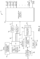
- the IPG 14 includes modulation output circuitry 50 configured for generating electrical modulation energy in accordance with an electrical pulse train having a programmed pulse amplitude, pulse rate, pulse width, duty cycle, burst rate, and shape under control of control logic 52 over data bus 54.
- the pulse rate and the duration of stimulation may be controlled by analog circuitry, or digital timer logic circuitry 56 controlling the analog circuitry, and which may have a suitable resolution, e.g., 10 ⁇ s.
- the modulation energy generated by the modulation output circuitry 50 is output via capacitors C1-C16 to electrical terminals 58 respectively corresponding to electrodes E1-E16.
- the modulation output circuitry 50 may either include independently controlled current sources for providing modulation pulses of a specified and known amperage to or from the electrical terminals 58, or independently controlled voltage sources for providing modulation pulses of a specified and known voltage at the electrical terminals 58 or to multiplexed current or voltage sources that are then connected to the electrical terminals 58
- This modulation output circuitry 50 including alternative embodiments of suitable output circuitry for performing the same function of generating modulation pulses of a prescribed amplitude and width, is described more fully in U.S. Patent Nos. 6,516,227 and 6,993,384 .
- the modulation output circuitry 50 is capable of delivering electrical energy to the electrodes 26 via the electrical terminals 58 at a series of incrementally increasing amplitude values when the calibration process is initiated, and for the purpose of evoking CAPs in the neural tissue in response to the series of incrementally increasing amplitude values and/or for delivering sub-threshold modulation therapy based on the perception threshold determined through the process of calibration.
- the modulation output circuitry 50 may either include independently controlled current sources for providing stimulation pulses of a specified and known amperage to or from the electrical terminals 58, or independently controlled voltage sources for providing stimulation pulses of a specified and known voltage at the electrical terminals 58 or to multiplexed current or voltage sources that are then connected to the electrical terminals 58.
- This modulation output circuitry 50 including alternative embodiments of suitable output circuitry for performing the same function of generating stimulation pulses of a prescribed amplitude and width, is described more fully in U.S. Patent Nos. 6,516,227 and 6,993,384 .
- the modulation output circuitry 50 is capable of delivering electrical energy to the electrodes 26 via the electrical terminals 58 for the purpose of providing therapy to the patient and/or evoking CAPs in the neural tissue during the calibration process described above.
- the IPG 14 also includes monitoring circuitry 60 for monitoring the status of various nodes or other points 62 throughout the IPG 14, e.g., power supply voltages, temperature, battery voltage, and the like.
- the electrodes 26 fit snugly within the epidural space of the spinal column, and because the tissue is conductive, electrical measurements can be taken from the electrodes 26 in order to determine the coupling efficiency between the respective electrode 26 and the tissue and/or to facilitate fault detection with respect to the connection between the electrodes 26 and the modulation output circuitry 60 of the IPG 14.
- the monitoring circuitry 60 is configured to measure characteristic(s) of the CAPs evoked in response to the stimulation of neural tissue via the modulation output circuitry 50 during the calibration process.
- the evoked potential measurement technique may be performed by generating an electrical field at one of the electrodes 26, which is strong enough to depolarize the neurons adjacent the stimulating electrode beyond a threshold level, thereby inducing the firing of an eCAP that propagates along the neural fibers.
- Such stimulation is preferably supra-threshold, but not uncomfortable.
- a suitable stimulation pulse for this purpose is, for example, 4 mA for 200 ⁇ s.
- the monitoring circuitry 60 may be coupled to various sensors. If the physiological measurements are electrical, the sensors may be one or more of the electrodes 26. For other types of non-electrical physiological information, however, separate sensors may be used for appropriate measurements.
- the IPG 14 further includes a control/processing circuitry in the form of a microcontroller ( ⁇ C) 64 (or a processor) that controls the control logic 52 over data bus 66, and obtains status data from the monitoring circuitry 60 via data bus 68.
- ⁇ C microcontroller
- the IPG 14 additionally controls the timer logic 56.
- the IPG 14 further includes memory 70 and oscillator and clock circuit 72 coupled to the microcontroller 64.
- the microcontroller 64 generates the necessary control and status signals, which allow the microcontroller 64 to control the operation of the IPG 14 in accordance with a selected operating program and modulation parameters.
- the microcontroller 64 is able to individually generate electrical energy at the electrodes 26 using the modulation output circuitry 50, in combination with the control logic 52 and timer logic 56, thereby allowing each electrode 26 to be paired or grouped with other electrodes 26, including the monopolar case electrode, to control the polarity, pulse amplitude, pulse rate, pulse width, and pulse duty cycle through which the electrical energy is provided.
- the microcontroller 64 initiates the calibration process in response to the event.
- the microcontroller 64 is also configured for initiating and performing the calibration process, including directing the modulation output circuitry 50 to deliver the electrical energy at increasing amplitude levels, directing the monitoring circuitry 60 to sense any eCAPs in response to the delivered electrical energy, determining the perception threshold of the patient in response to the sensing of the eCAPs, and computing a decreased amplitude suitable for sub-threshold modulation therapy based on the perception threshold.
- the memory 70 may store various data (e.g. modulation parameters, reference eCAPs, threshold values, etc.) and a series of instructions to be executed by the microcontroller 64.
- the microcontroller 64 in combination with the memory 70 and oscillator and clock circuit 72, thus include a microprocessor system that carries out a program function in accordance with a suitable program stored in the memory 70. Alternatively, for some applications, the control/processing functions may be carried out by a suitable state machine.
- the IPG 14 further includes an alternating current (AC) receiving coil 74 for receiving programming data (e.g., the operating program and/or modulation parameters) from the RC 16 and/or CP 18 in an appropriate modulated carrier signal, and charging and forward telemetry circuitry 76 for demodulating the carrier signal it receives through the AC receiving coil 74 to recover the programming data, which programming data is then stored within the memory 70, or within other memory elements (not shown) distributed throughout the IPG 14.
- AC alternating current
- the IPG 14 further includes a back telemetry circuitry 78 and an alternating current (AC) transmission coil 80 for sending informational data sensed through the monitoring circuitry 60 to the RC 16 and/or CP 18.
- the back telemetry features of the IPG 14 also allow its status to be checked. For example, when the RC 16 and/or CP 18 initiates a programming session with the IPG 14, the capacity of the battery is telemetered, so that the RC 16 and/or CP 18 can calculate the estimated time to recharge. Any changes made to the current modulation parameters are confirmed through back telemetry, thereby assuring that such changes have been correctly received and implemented within the implant system.
- all programmable settings stored within the IPG 14 may be uploaded to the RC 16 and/or CP 18.
- the measured eCAPs can be transmitted from the IPG 14 to the RC 16 or CP 18 via the back telemetry circuitry 78 and coil 80.
- the RC 16 or the CP 18 may perform the necessary routine to adjust the modulation parameters and transmit the adjusted set of modulation parameters to the IPG 14 so that the IPG 14 can generate the electrical modulation energy in accordance with the adjusted set of modulation parameters.
- the IPG 14 further includes a rechargeable power source 82 and power circuits 84 for providing the operating power to the IPG 14.
- the rechargeable power source 82 may, e.g., include a lithium-ion or lithium-ion polymer battery.
- the rechargeable battery 82 provides an unregulated voltage to the power circuits 84.
- the power circuits 84 generate the various voltages 86, some of which are regulated and some of which are not, as needed by the various circuits located within the IPG 14.
- the rechargeable power source 82 is recharged using rectified AC power (or DC power converted from AC power through other means, e.g., efficient AC-to-DC converter circuits, also known as "inverter circuits" received by the AC receiving coil 74.
- an external charger (not shown), which generates the AC magnetic field, is placed against, or otherwise adjacent, to the patient's skin over the implanted IPG 14.
- the AC magnetic field emitted by the external charger induces AC currents in the AC receiving coil 74.
- the charging and forward telemetry circuitry 76 rectifies the AC current to produce DC current, which is used to charge the power source 82. While the AC receiving coil 74 is described as being used for both wirelessly receiving communications (e.g., programming and control data) and charging energy from the external device, it should be appreciated that the AC receiving coil 74 can be arranged as a dedicated charging coil, while another coil, such as coil 80, can be used for bi-directional telemetry.
- the system 10 may alternatively utilize an implantable receiver-stimulator (not shown) connected to leads 12.
- the power source e.g., a battery
- the implanted receiver will be contained in an external controller inductively coupled to the receiver-stimulator via an electromagnetic link.
- Data/power signals are transcutaneously coupled from a cable-connected transmission coil placed over the implanted receiver-stimulator. The implanted receiver-stimulator receives the signal and generates the stimulation in accordance with the control signals.
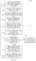
- the SCM system 10 delivers electrical modulation energy to a target tissue of the patient in accordance with the sub-threshold modulation program stored within the SCM system 10, thereby providing therapy to the patient without the perception of paresthesia (step 302).
- a calibration triggering event occurs (step 304).
- triggering event can be an identified triggering physical activity and/or posture, a user-initiated signal, a signal indicating electrode-migration or a predetermined periodically recurring signal.
- the SCM system 10 identifies the patient's physical activity and/or posture if it has not already been identified as a triggering event (step 306). Based on the patient/s physical activity and/or posture, the SCM system 10 selects, from the stored list of reference eCAPs, the reference eCAP corresponding to the identified physical activity and/or posture (step 308).
- the SCM system 10 delivers an electrical pulse train of a specified amplitude (which may initially be the programmed amplitude at which the electrical pulse train was delivered to provide the sub-threshold therapy), in response to which eCAP measurements are made for at least one pulse of the delivered electrical pulse train (step 310).
- a specified amplitude which may initially be the programmed amplitude at which the electrical pulse train was delivered to provide the sub-threshold therapy
- an eCAP measurement may be made after each pulse.
- the SCM system 10 compares the eCAP measurement(s) to the selected reference eCAP corresponding to the identified physical activity and/or posture (step 312).
- a characteristic e.g., amplitude, peak delay, width, morphology
- the SCM system 10 increases the amplitude of the delivered electrical energy by a step size (step 316), and returns to making eCAP measurement(s) in response to the delivered electrical energy at the increased amplitude (step 310). If the eCAP comparison reveals that the perception threshold of the patient has been reached (step 314), the SCM system 10 computes a decreased amplitude value as a function of the amplitude value indicative of the perception threshold (step 318). As described above, such function can be, e.g., a percentage of the determined perception threshold or a difference between the determined perception threshold and a constant.
- the SCM system 10 modifies the sub-threshold modulation program with the computed amplitude value (step 320) and returns to step 302 to direct the IPG 14 to deliver electrical modulation energy in accordance with a modified sub-threshold modulation program, thereby providing therapy to the patient without the perception of paresthesia.
- the sub-threshold calibration technique ensures that any intended sub-threshold therapy remains within an efficacious and energy efficient therapeutic window that may otherwise fall outside of this window due to environmental changes, such as lead migration or changes in patient's physical activity and/or posture.
- the sub-threshold calibration technique has been described with respect to sub-threshold therapy designed to treat chronic pain, it should be appreciated that this calibration technique can be utilized to calibrate any sub-threshold therapy provided to treat a patient with any disorder where the perception of paresthesia may be indicative of efficacious treatment of the disorder.
- the sub-threshold calibration technique has been described as being performed in the IPG 14, it should be appreciated that this technique could be performed in the CP 18, or even the RC 16.
- pulse width values may be incrementally increased relative to a programmed pulse width value while maintaining the amplitude value and pulse rate value the same, and computing a decreased pulse width value as a function of one of the increased pulse width value.
- the significance is that a parameter that directly effects the intensity of the electrical modulation energy in a controllable and predictable fashion is used to calibrate the sub-threshold therapy.
Landscapes
- Health & Medical Sciences (AREA)
- Life Sciences & Earth Sciences (AREA)
- Animal Behavior & Ethology (AREA)
- General Health & Medical Sciences (AREA)
- Biomedical Technology (AREA)
- Nuclear Medicine, Radiotherapy & Molecular Imaging (AREA)
- Radiology & Medical Imaging (AREA)
- Veterinary Medicine (AREA)
- Public Health (AREA)
- Engineering & Computer Science (AREA)
- Neurology (AREA)
- Neurosurgery (AREA)
- Pain & Pain Management (AREA)
- Biophysics (AREA)
- Physiology (AREA)
- Heart & Thoracic Surgery (AREA)
- Electrotherapy Devices (AREA)
Claims (15)
- Neuromodulationssystem, aufweisend:mehrere elektrische Anschlüsse (58), die jeweils konfiguriert sind, um mit mehreren Elektroden (26), die in einem Zielgewebeort implantiert sind, elektrisch gekoppelt zu werden;eine Modulationsausgabeschaltung (50), die mit den mehreren elektrischen Anschlüssen (58) gekoppelt ist, um dem Zielgewebeort des Patienten elektrische Modulationsenergie mit einem programmierten Intensitätswert zuzuführen, um dadurch dem Patienten eine Therapie ohne Stimulationsperzeption bereitzustellen;eine mit den mehreren elektrischen Anschlüssen (58) gekoppelte Überwachungsschaltung (60); undeine Steuerungs-/Verarbeitungsschaltung (64), die konfiguriert ist, um:(i) als Antwort auf ein Ereignis eine Kalibration der subperzeptiven Therapie zu initiieren, um eine Perzeptionsschwelle zu ermitteln und einen in der subperzeptiven Therapie zu verwendenden Intensitätswert als Funktion der Perzeptionsschwelle zu berechnen, wobei die Steuerungs-/Verarbeitungsschaltung (64) konfiguriert ist, umals Antwort auf das Ereignis die Modulationsausgabeschaltung (50) anzuweisen, elektrische Modulationsenergie mit einer Folge von Intensitätswerten, die relativ zu dem programmierten Intensitätswert schrittweise ansteigen, zuzuführen;die Überwachungsschaltung (60) zu veranlassen, als Antwort auf die Zuführung der elektrischen Modulationsenergie mit der Folge von schrittweise ansteigenden Intensitätswerten mindestens ein evoziertes zusammengesetztes Aktionspotential (eCAP), das die Perzeptionsschwelle in einer Neuronenpopulation in dem Zielgewebeort des Patienten anzeigt, zu detektieren;einen aus der Folge von schrittweise ansteigenden Intensitätswerten auszuwählen, der dem mindestens einen die Perzeptionsschwelle anzeigenden, detektierten eCAP entspricht; undautomatisch einen verringerten Wert als eine Funktion des ausgewählten Intensitätswerts zu berechnen; und(ii) die Modulationsausgabeschaltung (50) anzuweisen, dem Zielgewebeort des Patienten elektrische Modulationsenergie mit dem berechneten Intensitätswert zuzuführen, um die subperzeptive Therapie bereitzustellen.
- Neuromodulationssystem nach Anspruch 1, wobei die Stimulationsperzeption eine Parästhesie aufweist.
- Neuromodulationssystem nach Anspruch 1, wobei der programmierte Intensitätswert einen programmierten Amplitudenwert aufweist und die schrittweise ansteigenden Intensitätswerte schrittweise ansteigende Amplitudenwerte aufweisen.
- Neuromodulationssystem nach einem der Ansprüche 1 bis 3, wobei der programmierte Intensitätswert einen programmierten Pulsbreitenwert aufweist und die schrittweise ansteigenden Intensitätswerte schrittweise ansteigende Pulsbreitenwerte aufweisen.
- Neuromodulationssystem nach einem der vorstehenden Ansprüche, wobei der ausgewählte Intensitätswert dem Intensitätswert der zugeführten elektrischen Modulationsenergie entspricht, als Antwort auf welchen ein erstes des mindestens einen eCAP detektiert worden ist.
- Neuromodulationssystem nach einem der vorstehenden Ansprüche, ferner aufweisend:Speicher (70), die zum Speichern mindestens einer Eigenschaft eines eine Perzeptionsschwelle anzeigenden Referenz-eCAP konfiguriert sind, und wobei die Steuerungs-/Verarbeitungsschaltung (64) ferner konfiguriert ist, umeine Eigenschaft jedes des mindestens einen detektierten eCAP mit einer entsprechenden Eigenschaft eines Referenz-eCAP zu vergleichen; undauf Basis des Vergleichs einen aus der Folge von schrittweise ansteigenden Intensitätswerten auszuwählen.
- Neuromodulationssystem nach Anspruch 6, wobei die Eigenschaft des jeden detektierten eCAP mindestens eine ist von: Scheitelwertverzögerung, Breite, Amplitude und Wellenformmorphologie.
- Neuromodulationssystem nach einem der Ansprüche 6 bis 7, wobei das mindestens eine detektierte eCAP zwei oder mehr eCAPs aufweist, die jeweils als Antwort auf die Zuführung der elektrischen Modulationsenergie mit zwei oder mehr der Intensitätswerte detektiert worden sind, wobei die Steuerungs-/Verarbeitungsschaltung (64) ferner konfiguriert ist, um:die Eigenschaft aus dem gespeicherten Referenz-eCAP abzurufen;eines der zwei oder mehr detektierten eCAPs, dessen Eigenschaft am besten mit der Eigenschaft des Referenz-eCAP übereinstimmt, zu ermitteln; undden Intensitätswert der zugeführten elektrischen Modulationsenergie auszuwählen, als Antwort auf welchen das ermittelte eCAP detektiert worden ist.
- Neuromodulationssystem nach einem der Ansprüche 6 bis 8, wobei die Eigenschaft des Referenz-eCAP ein gespeicherter Schwellenwert ist, das mindestens eine detektierte eCAP ein oder mehr eCAPs aufweist, die jeweils als Antwort auf die Zuführung der elektrischen Modulationsenergie mit jedem von zwei oder mehr Intensitätswerten detektiert worden sind, wobei die Steuerungs-/Verarbeitungsschaltung (64) ferner konfiguriert ist, um:eine Funktion des einen oder der mehreren detektierten eCAPs mit der Eigenschaft, die gleich oder größer als der gespeicherte Schwellenwert ist, zu ermitteln;den Intensitätswert der zugeführten elektrischen Modulationsenergie auszuwählen, als Antwort auf welchen das ermittelte eine oder die ermittelten mehreren eCAPs detektiert worden sind.
- Neuromodulationssystem nach einem der Ansprüche 6 bis 9, wobei der Speicher ferner konfiguriert ist, um eine Liste von Referenz-eCAP-Eigenschaften zu speichern, die jeweils eine Perzeptionsschwelle anzeigen, wenn sich der Patient in einer speziellen körperlichen Aktivität und/oder Haltung befindet, wobei die Steuerungs-/Verarbeitungsschaltung (64) ferner konfiguriert ist, um:eine körperliche Aktivität und/oder Haltung zu erkennen, in welcher sich der Patient derzeit befindet;aus der Liste von Referenz-eCAP-Eigenschaften die Referenz-eCAP-Eigenschaft auszuwählen, die der erkannten körperlichen Aktivität und/oder Haltung entspricht; unddie Eigenschaft jedes des mindestens einen detektierten eCAP mit dem ausgewählten Referenz-eCAP zu vergleichen.
- Neuromodulationssystem nach einem der vorstehenden Ansprüche, wobei das Ereignis eines der folgenden ist: eine erkannte körperliche Aktivität und/oder Haltung, ein vom Benutzer initiiertes Signal, ein Signal, das eine Wanderung einer Elektrode (26), aus welcher die elektrische Modulationsenergie zugeführt wird, anzeigt, und ein vorgegebenes periodisch wiederkehrendes Signal.
- Neuromodulationssystem nach Anspruch 11, ferner aufweisend eine externe Steuervorrichtung (16, 18, 20) zur Erzeugung des vom Benutzer initiierten Signals.
- Neuromodulationssystem nach einem der vorstehenden Ansprüche, wobei der berechnete Intensitätswert ein Prozentsatz des ausgewählten Intensitätswerts ist, wobei der Prozentsatz im Bereich von 10%-90% des ausgewählten Intensitätswerts ist.
- Neuromodulationssystem nach einem der Ansprüche 1 bis 12, wobei der berechnete Intensitätswert eine Differenz zwischen dem ausgewählten Intensitätswert und einer Konstante ist.
- Neuromodulationssystem nach Anspruch 1, wobei sowohl die mit dem programmierten Intensitätswert zugeführte elektrische Modulationsenergie als auch die mit der Folge von schrittweise ansteigenden Intensitätswerten zugeführte elektrische Energie elektrische Pulssequenzen aufweist und wobei der programmierte Intensitätswert, der schrittweise ansteigende Intensitätswert und der berechnete Intensitätswert jeweils ein Pulsintensitätswert ist.
Applications Claiming Priority (2)
| Application Number | Priority Date | Filing Date | Title |
|---|---|---|---|
| US201361858730P | 2013-07-26 | 2013-07-26 | |
| PCT/US2014/047804 WO2015013398A1 (en) | 2013-07-26 | 2014-07-23 | Systems of providing modulation therapy without perception |
Publications (2)
| Publication Number | Publication Date |
|---|---|
| EP3024540A1 EP3024540A1 (de) | 2016-06-01 |
| EP3024540B1 true EP3024540B1 (de) | 2018-10-17 |
Family
ID=51303112
Family Applications (1)
| Application Number | Title | Priority Date | Filing Date |
|---|---|---|---|
| EP14750651.3A Active EP3024540B1 (de) | 2013-07-26 | 2014-07-23 | Systeme zur bereitstellung einer modulationstherapie ohne wahrnehmung |
Country Status (7)
| Country | Link |
|---|---|
| US (3) | US20150032181A1 (de) |
| EP (1) | EP3024540B1 (de) |
| JP (1) | JP6181307B2 (de) |
| CN (1) | CN105407964B (de) |
| AU (1) | AU2014293164B2 (de) |
| CA (1) | CA2917977A1 (de) |
| WO (1) | WO2015013398A1 (de) |
Cited By (15)
| Publication number | Priority date | Publication date | Assignee | Title |
|---|---|---|---|---|
| US11179567B2 (en) | 2019-12-19 | 2021-11-23 | Medtronic, Inc. | Hysteresis compensation for detection of ECAPs |
| US11202912B2 (en) | 2019-12-19 | 2021-12-21 | Medtronic, Inc. | Posture-based control of electrical stimulation therapy |
| US11439825B2 (en) | 2019-12-19 | 2022-09-13 | Medtronic, Inc. | Determining posture state from ECAPs |
| US11524163B2 (en) | 2013-07-26 | 2022-12-13 | Boston Scientific Neuromodulation Corporation | Systems and methods of providing modulation therapy without patient-perception of stimulation |
| US11547855B2 (en) | 2019-10-25 | 2023-01-10 | Medtronic, Inc. | ECAP sensing for high frequency neurostimulation |
| US11707626B2 (en) | 2020-09-02 | 2023-07-25 | Medtronic, Inc. | Analyzing ECAP signals |
| US11857793B2 (en) | 2020-06-10 | 2024-01-02 | Medtronic, Inc. | Managing storage of sensed information |
| US11931582B2 (en) | 2019-10-25 | 2024-03-19 | Medtronic, Inc. | Managing transient overstimulation based on ECAPs |
| US12011595B2 (en) | 2019-12-19 | 2024-06-18 | Medtronic, Inc. | Control pulses and posture for ECAPs |
| US12023501B2 (en) | 2018-06-21 | 2024-07-02 | Medtronic, Inc. | ECAP based control of electrical stimulation therapy |
| US12064631B2 (en) | 2019-12-19 | 2024-08-20 | Medtronic, Inc. | ECAP and posture state control of electrical stimulation |
| US12097373B2 (en) | 2020-06-10 | 2024-09-24 | Medtronic, Inc. | Control policy settings for electrical stimulation therapy |
| US12128235B2 (en) | 2020-03-06 | 2024-10-29 | Medtronic, Inc. | Controlling electrical stimulation based on a sensed stimulation signal |
| US12133982B2 (en) | 2018-06-21 | 2024-11-05 | Medtronic, Inc. | ECAP based control of electrical stimulation therapy |
| US12357830B2 (en) | 2019-10-25 | 2025-07-15 | Medtronic, Inc. | Sub-threshold stimulation based on ECAP detection |
Families Citing this family (70)
| Publication number | Priority date | Publication date | Assignee | Title |
|---|---|---|---|---|
| US20070073354A1 (en) | 2005-09-26 | 2007-03-29 | Knudson Mark B | Neural blocking therapy |
| US8255057B2 (en) | 2009-01-29 | 2012-08-28 | Nevro Corporation | Systems and methods for producing asynchronous neural responses to treat pain and/or other patient conditions |
| EP2586488B1 (de) * | 2009-04-22 | 2017-03-15 | Nevro Corporation | Selektive Hochfrequenzrückenmarksmodulation zur Vermeidung von Schmerzen mit weniger Nebenwirkungen, sowie zugehörige Systeme |
| EP2421600B1 (de) | 2009-04-22 | 2014-03-05 | Nevro Corporation | Rückenmarksmodulationssyteme zur induzierung von parästhetischen und anästhetischen effekten |
| WO2012155185A1 (en) | 2011-05-13 | 2012-11-22 | National Ict Australia Ltd | Method and apparatus for measurement of neural response |
| AU2012304370B2 (en) | 2011-09-08 | 2016-01-28 | Nevro Corporation | Selective high frequency spinal cord modulation for inhibiting pain, including cephalic and/or total body pain with reduced side effects, and associated systems and methods |
| US9833614B1 (en) | 2012-06-22 | 2017-12-05 | Nevro Corp. | Autonomic nervous system control via high frequency spinal cord modulation, and associated systems and methods |
| JP2016512758A (ja) | 2013-03-15 | 2016-05-09 | ボストン サイエンティフィック ニューロモデュレイション コーポレイション | 閾値以下の治療を患者に提供するシステム及び方法 |
| WO2014197564A1 (en) | 2013-06-06 | 2014-12-11 | Boston Scientific Neuromodulation Corporation | System for delivering sub-threshold and super-threshold therapy |
| US9895539B1 (en) | 2013-06-10 | 2018-02-20 | Nevro Corp. | Methods and systems for disease treatment using electrical stimulation |
| CA2924817C (en) | 2013-09-16 | 2023-09-19 | The Board Of Trustees Of The Leland Stanford Junior University | Multi-element coupler for generation of electromagnetic energy |
| US10149978B1 (en) | 2013-11-07 | 2018-12-11 | Nevro Corp. | Spinal cord modulation for inhibiting pain via short pulse width waveforms, and associated systems and methods |
| AU2014351064B2 (en) | 2013-11-15 | 2019-07-04 | Closed Loop Medical Pty Ltd | Monitoring brain neural potentials |
| WO2015143509A1 (en) | 2014-03-28 | 2015-10-01 | Saluda Medical Pty Ltd | Assessing neural state from action potentials |
| WO2015179225A1 (en) | 2014-05-18 | 2015-11-26 | Yeh Alexander Jueshyan | Midfield coupler |
| US20160336813A1 (en) | 2015-05-15 | 2016-11-17 | NeuSpera Medical Inc. | Midfield coupler |
| EP3180069B1 (de) | 2014-08-17 | 2020-05-13 | Nine Continents Medical, Inc. | Implantierbares miniaturneurostimulatorsystem für ischiasnerven und deren verzweigungen |
| US12053630B2 (en) | 2014-08-17 | 2024-08-06 | Coloplast A/S | Implantable pulse generator with automatic jump-start |
| US10493276B2 (en) * | 2014-09-23 | 2019-12-03 | Boston Scientific Neuromodulation Corporation | Neuromodulation specific to objective function of modulation field for targeted tissue |
| AU2015349614B2 (en) | 2014-11-17 | 2020-10-22 | Saluda Medical Pty Ltd | Method and device for detecting a neural response in neural measurements |
| WO2016161484A2 (en) * | 2015-04-09 | 2016-10-13 | Saluda Medical Pty Ltd | Electrode to nerve distance estimation |
| EP3288633B1 (de) | 2015-04-29 | 2021-05-26 | Boston Scientific Neuromodulation Corporation | System zur vorbereitung einer neuromodulation für schnellere therapeutische reaktion |
| US10076667B2 (en) | 2015-06-09 | 2018-09-18 | Nuvectra Corporation | System and method of performing computer assisted stimulation programming (CASP) with a non-zero starting value customized to a patient |
| US10052490B2 (en) | 2015-06-09 | 2018-08-21 | Nuvectra Corporation | Systems, methods, and devices for performing electronically controlled test stimulation |
| US10744323B2 (en) | 2015-08-18 | 2020-08-18 | Advanced Bionics Ag | Cochlear implant system |
| US11318310B1 (en) | 2015-10-26 | 2022-05-03 | Nevro Corp. | Neuromodulation for altering autonomic functions, and associated systems and methods |
| US11331489B2 (en) | 2015-12-18 | 2022-05-17 | Medtronic, Inc. | High duty cycle electrical stimulation therapy |
| US9925379B2 (en) * | 2015-12-22 | 2018-03-27 | Pacesetter, Inc. | System and method for managing stimulation of select A-beta fiber components |
| AU2017211121B2 (en) | 2016-01-25 | 2022-02-24 | Nevro Corp. | Treatment of congestive heart failure with electrical stimulation, and associated systems and methods |
| US11191966B2 (en) | 2016-04-05 | 2021-12-07 | Saluda Medical Pty Ltd | Feedback control of neuromodulation |
| US10406368B2 (en) * | 2016-04-19 | 2019-09-10 | Boston Scientific Neuromodulation Corporation | Pulse generator system for promoting desynchronized firing of recruited neural populations |
| WO2017210382A1 (en) | 2016-06-02 | 2017-12-07 | Boston Scientific Neuromodulation Corporation | Automatic initiation of priming at startup of neuromodulation device |
| US10456583B2 (en) * | 2016-06-02 | 2019-10-29 | Boston Scientific Neuromodulation Corporation | Customized priming by neuromodulation device |
| EP3474747B1 (de) | 2016-06-24 | 2026-04-22 | Saluda Medical Pty Ltd | Nervenstimulation für reduziertes artefakt |
| WO2018039117A1 (en) | 2016-08-22 | 2018-03-01 | Boston Scientific Neuromodulation Corporation | Neuromodulation system for providing paresthesia and analgesia and a system with leads and with electrodes |
| US10525268B2 (en) | 2016-08-23 | 2020-01-07 | Medtronic, Inc. | Delivery of independent interleaved programs to produce higher-frequency electrical stimulation therapy |
| EP3532152B1 (de) * | 2016-10-28 | 2020-11-25 | Medtronic, Inc. | Hochfrequenzstimulation auf basis eines niederfrequenz-titrationsmessgeräts |
| EP4190394B1 (de) | 2016-11-23 | 2026-02-18 | Boston Scientific Neuromodulation Corporation | Systeme zur programmierung einer neuromodulationswellenform |
| US10617872B2 (en) | 2016-11-23 | 2020-04-14 | Boston Scientific Neuromodulation Corporation | Systems and methods for programming neuromodulation therapy |
| US10933242B2 (en) * | 2017-09-29 | 2021-03-02 | Medtronic, Inc. | Therapy parameter selection based on ECAP feedback |
| EP3691744B1 (de) | 2017-10-04 | 2021-07-28 | Boston Scientific Neuromodulation Corporation | Anpassung der stimulation bei einem stimulator unter verwendung detektierter evozierter verbindungsaktionspotenziale |
| US10987515B2 (en) | 2017-10-10 | 2021-04-27 | Medtronic, Inc. | Management of electrical stimulation therapy |
| AU2019205211B2 (en) * | 2018-01-08 | 2021-08-05 | Boston Scientific Neuromodulation Corporation | Automatic adjustment of sub-perception therapy in an implantable stimulator using detected compound action potentials |
| EP3765145B1 (de) | 2018-03-12 | 2024-04-24 | Boston Scientific Neuromodulation Corporation | Neurale stimulation basierend auf zerlegung der evozierten summenaktionspotenziale |
| EP3781252B1 (de) | 2018-04-16 | 2024-11-20 | University of Pittsburgh - of the Commonwealth System of Higher Education | Nervenblockade durch elektrische impulse mit unterschwellenintensität |
| EP4434461A3 (de) | 2018-04-27 | 2025-03-05 | Saluda Medical Pty Ltd | Neurostimulation gemischter nerven |
| US12370079B2 (en) | 2018-06-19 | 2025-07-29 | Thermaquil, Inc. | Apparatus and method for thermal blockade of nerves |
| JP7466537B2 (ja) * | 2018-11-02 | 2024-04-12 | サルーダ・メディカル・ピーティーワイ・リミテッド | 電気神経刺激療法の治療効果を評価するためのシステム及び非一時的コンピュータ可読媒体 |
| US11590352B2 (en) | 2019-01-29 | 2023-02-28 | Nevro Corp. | Ramped therapeutic signals for modulating inhibitory interneurons, and associated systems and methods |
| US11484719B2 (en) * | 2019-02-13 | 2022-11-01 | Medtronic, Inc. | Electrical stimulation rate modulation for communication of data values in a medical device system |
| CN113950282B (zh) * | 2019-06-12 | 2024-06-04 | 波士顿科学神经调制公司 | 使用感测刺激伪迹在脊髓刺激器系统中的姿势确定及刺激调节 |
| US11638821B2 (en) | 2019-07-30 | 2023-05-02 | Medtronic, Inc. | Incontinence therapy |
| US11383086B2 (en) * | 2019-07-30 | 2022-07-12 | Medtronic, Inc. | Posture-based paresthesia threshold or perception threshold determination |
| US11311729B2 (en) * | 2019-07-30 | 2022-04-26 | Medtronic, Inc. | Titration for sub-threshold electrical stimulation therapy |
| US12370365B2 (en) | 2019-08-09 | 2025-07-29 | Boston Scientific Neuromodulation Corporation | Systems for noise-sensitive patient-specific adjustments of neuromodulation parameters |
| EP4048368B1 (de) * | 2019-10-21 | 2024-05-29 | Boston Scientific Neuromodulation Corporation | Bewertung und einstellung von zeitlich variierenden impulsmustern in einem rückenmarkenstimulatorsystem |
| US11839767B2 (en) | 2020-01-10 | 2023-12-12 | Nuxcel2, L.L.C. | Systems and methods for stimulation of cranial nerves |
| US12076564B2 (en) | 2020-04-14 | 2024-09-03 | Medtronic, Inc. | Patient specific optimization algorithm |
| US11944819B2 (en) | 2020-07-09 | 2024-04-02 | Medtronic, Inc. | Analyzing ECAP signals |
| US11786734B2 (en) * | 2020-08-07 | 2023-10-17 | Medtronic, Inc. | Implantable lead migration monitoring using ECAP |
| US11896828B2 (en) | 2020-10-30 | 2024-02-13 | Medtronic, Inc. | Implantable lead location using ECAP |
| US12311184B2 (en) | 2020-11-02 | 2025-05-27 | Medtronic, Inc. | Method and user interface for managing duty-cycled electrical nerve stimulation |
| US12274878B2 (en) | 2020-11-06 | 2025-04-15 | Medtronic, Inc. | Low healthcare provider interaction and outcome based programming |
| EP4274656A1 (de) * | 2021-01-08 | 2023-11-15 | Medtronic, Inc. | Bestimmung des geschätzten neuronalen schwellenwerts mit ecap-signalen |
| EP4347001B1 (de) | 2021-05-25 | 2026-03-25 | Nevro Corp. | Modifizierte hochfrequenz-neuromodulationssignale sowie zugehörige systeme |
| JP2024532410A (ja) * | 2021-08-24 | 2024-09-05 | アビボメッド インコーポレイテッド | 治療フィードバックを伴う脳神経刺激装置 |
| AU2022380481B2 (en) | 2021-11-05 | 2025-08-14 | Boston Scientific Neuromodulation Corporation | Closed loop stimulation based on response avoidance |
| US20240066302A1 (en) * | 2022-03-07 | 2024-02-29 | Ian Loren Halpern | Adaptive neural interface |
| EP4683708A1 (de) * | 2023-03-22 | 2026-01-28 | BIOTRONIK SE & Co. KG | Automatisierter wahrnehmungsschwellentest und therapieanpassung zur rückenmarksstimulation |
| WO2025042775A1 (en) * | 2023-08-18 | 2025-02-27 | Stimmed Llc | Method and apparatus for noninvasive inhibition of deep vein thrombosis |
Citations (1)
| Publication number | Priority date | Publication date | Assignee | Title |
|---|---|---|---|---|
| WO2010111358A2 (en) * | 2009-03-24 | 2010-09-30 | Spinal Modulation, Inc. | Pain management with stimulation subthreshold to parasthesia |
Family Cites Families (53)
| Publication number | Priority date | Publication date | Assignee | Title |
|---|---|---|---|---|
| US5938690A (en) * | 1996-06-07 | 1999-08-17 | Advanced Neuromodulation Systems, Inc. | Pain management system and method |
| US5941906A (en) * | 1997-10-15 | 1999-08-24 | Medtronic, Inc. | Implantable, modular tissue stimulator |
| US6421566B1 (en) | 1998-04-30 | 2002-07-16 | Medtronic, Inc. | Selective dorsal column stimulation in SCS, using conditioning pulses |
| US6516227B1 (en) | 1999-07-27 | 2003-02-04 | Advanced Bionics Corporation | Rechargeable spinal cord stimulator system |
| US6993384B2 (en) | 2001-12-04 | 2006-01-31 | Advanced Bionics Corporation | Apparatus and method for determining the relative position and orientation of neurostimulation leads |
| US7317948B1 (en) | 2002-02-12 | 2008-01-08 | Boston Scientific Scimed, Inc. | Neural stimulation system providing auto adjustment of stimulus output as a function of sensed impedance |
| DE60331351D1 (de) * | 2002-12-06 | 2010-04-01 | Boston Scient Neuromodulation | Verfahren zur feststellung von stimulationsparametern |
| EP1648557A1 (de) | 2003-07-18 | 2006-04-26 | CAMPBELL, James, N. | Behandlung von schmerzen |
| US20050203600A1 (en) | 2004-03-12 | 2005-09-15 | Scimed Life Systems, Inc. | Collapsible/expandable tubular electrode leads |
| US7539538B2 (en) | 2004-05-28 | 2009-05-26 | Boston Science Neuromodulation Corporation | Low power loss current digital-to-analog converter used in an implantable pulse generator |
| AU2005282379B8 (en) | 2004-09-08 | 2012-04-05 | Spinal Modulation Inc. | Neurostimulation methods and systems |
| US8332047B2 (en) * | 2004-11-18 | 2012-12-11 | Cardiac Pacemakers, Inc. | System and method for closed-loop neural stimulation |
| US8019439B2 (en) | 2005-01-11 | 2011-09-13 | Boston Scientific Neuromodulation Corporation | Lead assembly and method of making same |
| US7561918B2 (en) * | 2005-01-28 | 2009-07-14 | Cyberonics, Inc. | Autocapture in a neurostimulator |
| US8644941B2 (en) | 2005-06-09 | 2014-02-04 | Medtronic, Inc. | Peripheral nerve field stimulation and spinal cord stimulation |
| US20070021803A1 (en) | 2005-07-22 | 2007-01-25 | The Foundry Inc. | Systems and methods for neuromodulation for treatment of pain and other disorders associated with nerve conduction |
| US7650184B2 (en) | 2005-12-01 | 2010-01-19 | Boston Scientific Neuromodulation Corporation | Cylindrical multi-contact electrode lead for neural stimulation and method of making same |
| US8700178B2 (en) | 2005-12-27 | 2014-04-15 | Boston Scientific Neuromodulation Corporation | Stimulator leads and methods for lead fabrication |
| WO2007087626A2 (en) | 2006-01-26 | 2007-08-02 | Advanced Neuromodulation Systems, Inc. | Method of neurosimulation of distinct neural structures using single paddle lead |
| US7869885B2 (en) * | 2006-04-28 | 2011-01-11 | Cyberonics, Inc | Threshold optimization for tissue stimulation therapy |
| EP2091606B1 (de) * | 2006-12-13 | 2016-05-25 | Medtronic Bakken Research Center B.V. | Auf anhieb richtige platzierung einer dbs-leitung |
| JP5224478B2 (ja) | 2007-02-01 | 2013-07-03 | ボストン サイエンティフィック ニューロモデュレイション コーポレイション | 患者の活動を計測する神経刺激システム |
| US8224453B2 (en) | 2007-03-15 | 2012-07-17 | Advanced Neuromodulation Systems, Inc. | Spinal cord stimulation to treat pain |
| EP2152361A1 (de) * | 2007-04-19 | 2010-02-17 | Northstar Neuroscience, Inc. | Verfahren und systeme zur etablierung von nervenstimulationsparametern und für nervenstimulation |
| US20090204173A1 (en) | 2007-11-05 | 2009-08-13 | Zi-Ping Fang | Multi-Frequency Neural Treatments and Associated Systems and Methods |
| US9278222B2 (en) | 2008-07-11 | 2016-03-08 | Boston Scientific Neuromodulation Corporation | System and method for converting tissue stimulation programs in a format usable by an electrical current steering navigator |
| US8255057B2 (en) | 2009-01-29 | 2012-08-28 | Nevro Corporation | Systems and methods for producing asynchronous neural responses to treat pain and/or other patient conditions |
| US20100121409A1 (en) | 2008-11-12 | 2010-05-13 | Sridhar Kothandaraman | System and method for determining appropriate steering tables for distributing stimulation energy among multiple neurostimulation electrodes |
| US8504160B2 (en) | 2008-11-14 | 2013-08-06 | Boston Scientific Neuromodulation Corporation | System and method for modulating action potential propagation during spinal cord stimulation |
| CA2751579A1 (en) | 2009-02-10 | 2010-08-19 | Nevro Corporation | Systems and methods for delivering neural therapy correlated with patient status |
| AU2010239381B2 (en) | 2009-04-20 | 2015-01-15 | Monsanto Technology Llc | Multiple virus resistance in plants |
| EP2421600B1 (de) | 2009-04-22 | 2014-03-05 | Nevro Corporation | Rückenmarksmodulationssyteme zur induzierung von parästhetischen und anästhetischen effekten |
| EP2586488B1 (de) | 2009-04-22 | 2017-03-15 | Nevro Corporation | Selektive Hochfrequenzrückenmarksmodulation zur Vermeidung von Schmerzen mit weniger Nebenwirkungen, sowie zugehörige Systeme |
| AU2011267992B2 (en) * | 2010-06-18 | 2013-10-24 | Cardiac Pacemakers, Inc. | Neurostimulation system with control using evoked responses |
| US8805519B2 (en) | 2010-09-30 | 2014-08-12 | Nevro Corporation | Systems and methods for detecting intrathecal penetration |
| US8731675B2 (en) | 2010-10-06 | 2014-05-20 | Boston Scientific Neuromodulation Corporation | Neurostimulation system and method for providing therapy to patient with minimal side effects |
| WO2012075198A2 (en) | 2010-11-30 | 2012-06-07 | Nevro Corporation | Extended pain relief via high frequency spinal cord modulation, and associated systems and methods |
| US20120253422A1 (en) | 2011-03-30 | 2012-10-04 | Nevro Corporation | Systems and methods for selecting neural modulation contacts from among multiple contacts |
| US20120265279A1 (en) | 2011-04-13 | 2012-10-18 | Boston Scientific Neuromodulation Corporation | Sensing device for indicating posture of patient implanted with a neurostimulation device |
| CA2835818A1 (en) | 2011-05-13 | 2012-11-22 | Boston Scientific Neuromodulation Corporation | Neurostimulation system with on-effector programmer control |
| EP3357533B1 (de) * | 2011-05-13 | 2021-08-11 | Saluda Medical Pty Ltd | Vorrichtung zur steuerung eines neuronalen stimulus |
| AU2012304370B2 (en) | 2011-09-08 | 2016-01-28 | Nevro Corporation | Selective high frequency spinal cord modulation for inhibiting pain, including cephalic and/or total body pain with reduced side effects, and associated systems and methods |
| US9814884B2 (en) | 2011-11-04 | 2017-11-14 | Nevro Corp. | Systems and methods for detecting faults and/or adjusting electrical therapy based on impedance changes |
| US9504838B2 (en) | 2011-11-18 | 2016-11-29 | Boston Scientific Neuromodulation Corporation | Technique for linking electrodes together during programming of neurostimulation system |
| US8676331B2 (en) | 2012-04-02 | 2014-03-18 | Nevro Corporation | Devices for controlling spinal cord modulation for inhibiting pain, and associated systems and methods, including controllers for automated parameter selection |
| US9604058B2 (en) | 2012-04-06 | 2017-03-28 | Boston Scientific Neuromodulation Corporation | Method for achieving low-back spinal cord stimulation without significant side-effects |
| US8751009B2 (en) * | 2012-04-24 | 2014-06-10 | Medtronic, Inc. | Techniques for confirming a volume of effect of sub-perception threshold stimulation therapy |
| US9002459B2 (en) | 2012-09-19 | 2015-04-07 | Boston Scientific Neuromodulation Corporation | Method for selectively modulating neural elements in the dorsal horn |
| JP2016512758A (ja) | 2013-03-15 | 2016-05-09 | ボストン サイエンティフィック ニューロモデュレイション コーポレイション | 閾値以下の治療を患者に提供するシステム及び方法 |
| US20140276194A1 (en) * | 2013-03-15 | 2014-09-18 | Flint Hills Scientific, L.L.C. | Automated means to control responses to repetitive electrical stimulation and improve therapeutic efficacy |
| US20140277282A1 (en) * | 2013-03-15 | 2014-09-18 | Boston Scientific Neuromodulation Corporation | Use of compound action potentials to automatically adjust neurostimulation therapy in response to postural changes of patient |
| US9539422B2 (en) * | 2013-07-02 | 2017-01-10 | Greatbatch Ltd. | Neurostimulator interconnection apparatus, system, and method |
| CN105407964B (zh) | 2013-07-26 | 2018-05-04 | 波士顿科学神经调制公司 | 提供调制治疗而无感知的系统 |
-
2014
- 2014-07-23 CN CN201480042328.8A patent/CN105407964B/zh not_active Expired - Fee Related
- 2014-07-23 EP EP14750651.3A patent/EP3024540B1/de active Active
- 2014-07-23 AU AU2014293164A patent/AU2014293164B2/en active Active
- 2014-07-23 JP JP2016529858A patent/JP6181307B2/ja not_active Expired - Fee Related
- 2014-07-23 US US14/338,695 patent/US20150032181A1/en not_active Abandoned
- 2014-07-23 WO PCT/US2014/047804 patent/WO2015013398A1/en not_active Ceased
- 2014-07-23 CA CA2917977A patent/CA2917977A1/en not_active Abandoned
-
2019
- 2019-03-20 US US16/359,191 patent/US11524163B2/en active Active
-
2022
- 2022-11-14 US US17/986,698 patent/US12303695B2/en active Active
Patent Citations (1)
| Publication number | Priority date | Publication date | Assignee | Title |
|---|---|---|---|---|
| WO2010111358A2 (en) * | 2009-03-24 | 2010-09-30 | Spinal Modulation, Inc. | Pain management with stimulation subthreshold to parasthesia |
Cited By (23)
| Publication number | Priority date | Publication date | Assignee | Title |
|---|---|---|---|---|
| US11524163B2 (en) | 2013-07-26 | 2022-12-13 | Boston Scientific Neuromodulation Corporation | Systems and methods of providing modulation therapy without patient-perception of stimulation |
| US12303695B2 (en) | 2013-07-26 | 2025-05-20 | Boston Scientific Neuromodulation Corporation | Systems and methods of providing modulation therapy without patient-perception of stimulation |
| US12133982B2 (en) | 2018-06-21 | 2024-11-05 | Medtronic, Inc. | ECAP based control of electrical stimulation therapy |
| US12023501B2 (en) | 2018-06-21 | 2024-07-02 | Medtronic, Inc. | ECAP based control of electrical stimulation therapy |
| US11931582B2 (en) | 2019-10-25 | 2024-03-19 | Medtronic, Inc. | Managing transient overstimulation based on ECAPs |
| US12370366B2 (en) | 2019-10-25 | 2025-07-29 | Medtronic, Inc. | ECAP sensing for high frequency neurostimulation |
| US12357830B2 (en) | 2019-10-25 | 2025-07-15 | Medtronic, Inc. | Sub-threshold stimulation based on ECAP detection |
| US11547855B2 (en) | 2019-10-25 | 2023-01-10 | Medtronic, Inc. | ECAP sensing for high frequency neurostimulation |
| US12121730B2 (en) | 2019-12-19 | 2024-10-22 | Medtronic, Inc. | Determining posture state from ECAPs |
| US12168131B2 (en) | 2019-12-19 | 2024-12-17 | Medtronic, Inc. | Posture-based control of electrical stimulation therapy |
| US12011595B2 (en) | 2019-12-19 | 2024-06-18 | Medtronic, Inc. | Control pulses and posture for ECAPs |
| US11813457B2 (en) | 2019-12-19 | 2023-11-14 | Medtronic, Inc. | Hysteresis compensation for detection of ECAPs |
| US11202912B2 (en) | 2019-12-19 | 2021-12-21 | Medtronic, Inc. | Posture-based control of electrical stimulation therapy |
| US12064631B2 (en) | 2019-12-19 | 2024-08-20 | Medtronic, Inc. | ECAP and posture state control of electrical stimulation |
| US11439825B2 (en) | 2019-12-19 | 2022-09-13 | Medtronic, Inc. | Determining posture state from ECAPs |
| US11179567B2 (en) | 2019-12-19 | 2021-11-23 | Medtronic, Inc. | Hysteresis compensation for detection of ECAPs |
| US12186566B2 (en) | 2019-12-19 | 2025-01-07 | Medtronic, Inc. | Hysteresis compensation for detection of ECAPs |
| US11779765B2 (en) | 2019-12-19 | 2023-10-10 | Medtronic, Inc. | Posture-based control of electrical stimulation therapy |
| US12128235B2 (en) | 2020-03-06 | 2024-10-29 | Medtronic, Inc. | Controlling electrical stimulation based on a sensed stimulation signal |
| US11857793B2 (en) | 2020-06-10 | 2024-01-02 | Medtronic, Inc. | Managing storage of sensed information |
| US12097373B2 (en) | 2020-06-10 | 2024-09-24 | Medtronic, Inc. | Control policy settings for electrical stimulation therapy |
| US11707626B2 (en) | 2020-09-02 | 2023-07-25 | Medtronic, Inc. | Analyzing ECAP signals |
| US12036412B2 (en) | 2020-09-02 | 2024-07-16 | Medtronic, Inc. | Analyzing ECAP signals |
Also Published As
| Publication number | Publication date |
|---|---|
| US12303695B2 (en) | 2025-05-20 |
| EP3024540A1 (de) | 2016-06-01 |
| JP6181307B2 (ja) | 2017-08-16 |
| US20230072802A1 (en) | 2023-03-09 |
| JP2016525414A (ja) | 2016-08-25 |
| CN105407964B (zh) | 2018-05-04 |
| US11524163B2 (en) | 2022-12-13 |
| WO2015013398A1 (en) | 2015-01-29 |
| US20150032181A1 (en) | 2015-01-29 |
| CA2917977A1 (en) | 2015-01-29 |
| AU2014293164B2 (en) | 2017-07-06 |
| AU2014293164A1 (en) | 2016-02-11 |
| US20190217092A1 (en) | 2019-07-18 |
| CN105407964A (zh) | 2016-03-16 |
Similar Documents
| Publication | Publication Date | Title |
|---|---|---|
| US12303695B2 (en) | Systems and methods of providing modulation therapy without patient-perception of stimulation | |
| US11259732B2 (en) | Method and device for acquiring physiological data during tissue stimulation procedure | |
| US11040206B2 (en) | System and method for delivering sub-threshold and super-threshold therapy to a patient | |
| US9878158B2 (en) | Neuromodulation system and method for reducing energy requirements using feedback | |
| JP6400028B2 (ja) | 複合パルス列を生成するために柔軟性の増大した神経刺激システム | |
| US10029102B2 (en) | System and method for delivering modulated sub-threshold therapy to a patient | |
| AU2008210293B2 (en) | Neurostimulation system for measuring patient activity | |
| US20140277282A1 (en) | Use of compound action potentials to automatically adjust neurostimulation therapy in response to postural changes of patient | |
| JP2016507334A (ja) | パルス列を組み合わせる手段を有する多チャネル神経変調システム |
Legal Events
| Date | Code | Title | Description |
|---|---|---|---|
| PUAI | Public reference made under article 153(3) epc to a published international application that has entered the european phase |
Free format text: ORIGINAL CODE: 0009012 |
|
| 17P | Request for examination filed |
Effective date: 20160203 |
|
| AK | Designated contracting states |
Kind code of ref document: A1 Designated state(s): AL AT BE BG CH CY CZ DE DK EE ES FI FR GB GR HR HU IE IS IT LI LT LU LV MC MK MT NL NO PL PT RO RS SE SI SK SM TR |
|
| AX | Request for extension of the european patent |
Extension state: BA ME |
|
| DAX | Request for extension of the european patent (deleted) | ||
| STAA | Information on the status of an ep patent application or granted ep patent |
Free format text: STATUS: EXAMINATION IS IN PROGRESS |
|
| 17Q | First examination report despatched |
Effective date: 20170915 |
|
| GRAP | Despatch of communication of intention to grant a patent |
Free format text: ORIGINAL CODE: EPIDOSNIGR1 |
|
| STAA | Information on the status of an ep patent application or granted ep patent |
Free format text: STATUS: GRANT OF PATENT IS INTENDED |
|
| INTG | Intention to grant announced |
Effective date: 20180425 |
|
| RIN1 | Information on inventor provided before grant (corrected) |
Inventor name: BAYNHAM, TAMARA C. Inventor name: PARRAMON, JORDI |
|
| GRAS | Grant fee paid |
Free format text: ORIGINAL CODE: EPIDOSNIGR3 |
|
| GRAA | (expected) grant |
Free format text: ORIGINAL CODE: 0009210 |
|
| STAA | Information on the status of an ep patent application or granted ep patent |
Free format text: STATUS: THE PATENT HAS BEEN GRANTED |
|
| AK | Designated contracting states |
Kind code of ref document: B1 Designated state(s): AL AT BE BG CH CY CZ DE DK EE ES FI FR GB GR HR HU IE IS IT LI LT LU LV MC MK MT NL NO PL PT RO RS SE SI SK SM TR |
|
| REG | Reference to a national code |
Ref country code: GB Ref legal event code: FG4D |
|
| REG | Reference to a national code |
Ref country code: CH Ref legal event code: EP |
|
| REG | Reference to a national code |
Ref country code: IE Ref legal event code: FG4D |
|
| REG | Reference to a national code |
Ref country code: DE Ref legal event code: R096 Ref document number: 602014034267 Country of ref document: DE Ref country code: AT Ref legal event code: REF Ref document number: 1053284 Country of ref document: AT Kind code of ref document: T Effective date: 20181115 |
|
| REG | Reference to a national code |
Ref country code: NL Ref legal event code: FP |
|
| REG | Reference to a national code |
Ref country code: LT Ref legal event code: MG4D |
|
| REG | Reference to a national code |
Ref country code: AT Ref legal event code: MK05 Ref document number: 1053284 Country of ref document: AT Kind code of ref document: T Effective date: 20181017 |
|
| PG25 | Lapsed in a contracting state [announced via postgrant information from national office to epo] |
Ref country code: IS Free format text: LAPSE BECAUSE OF FAILURE TO SUBMIT A TRANSLATION OF THE DESCRIPTION OR TO PAY THE FEE WITHIN THE PRESCRIBED TIME-LIMIT Effective date: 20190217 Ref country code: FI Free format text: LAPSE BECAUSE OF FAILURE TO SUBMIT A TRANSLATION OF THE DESCRIPTION OR TO PAY THE FEE WITHIN THE PRESCRIBED TIME-LIMIT Effective date: 20181017 Ref country code: BG Free format text: LAPSE BECAUSE OF FAILURE TO SUBMIT A TRANSLATION OF THE DESCRIPTION OR TO PAY THE FEE WITHIN THE PRESCRIBED TIME-LIMIT Effective date: 20190117 Ref country code: PL Free format text: LAPSE BECAUSE OF FAILURE TO SUBMIT A TRANSLATION OF THE DESCRIPTION OR TO PAY THE FEE WITHIN THE PRESCRIBED TIME-LIMIT Effective date: 20181017 Ref country code: HR Free format text: LAPSE BECAUSE OF FAILURE TO SUBMIT A TRANSLATION OF THE DESCRIPTION OR TO PAY THE FEE WITHIN THE PRESCRIBED TIME-LIMIT Effective date: 20181017 Ref country code: LV Free format text: LAPSE BECAUSE OF FAILURE TO SUBMIT A TRANSLATION OF THE DESCRIPTION OR TO PAY THE FEE WITHIN THE PRESCRIBED TIME-LIMIT Effective date: 20181017 Ref country code: ES Free format text: LAPSE BECAUSE OF FAILURE TO SUBMIT A TRANSLATION OF THE DESCRIPTION OR TO PAY THE FEE WITHIN THE PRESCRIBED TIME-LIMIT Effective date: 20181017 Ref country code: AT Free format text: LAPSE BECAUSE OF FAILURE TO SUBMIT A TRANSLATION OF THE DESCRIPTION OR TO PAY THE FEE WITHIN THE PRESCRIBED TIME-LIMIT Effective date: 20181017 Ref country code: LT Free format text: LAPSE BECAUSE OF FAILURE TO SUBMIT A TRANSLATION OF THE DESCRIPTION OR TO PAY THE FEE WITHIN THE PRESCRIBED TIME-LIMIT Effective date: 20181017 Ref country code: NO Free format text: LAPSE BECAUSE OF FAILURE TO SUBMIT A TRANSLATION OF THE DESCRIPTION OR TO PAY THE FEE WITHIN THE PRESCRIBED TIME-LIMIT Effective date: 20190117 |
|
| PG25 | Lapsed in a contracting state [announced via postgrant information from national office to epo] |
Ref country code: PT Free format text: LAPSE BECAUSE OF FAILURE TO SUBMIT A TRANSLATION OF THE DESCRIPTION OR TO PAY THE FEE WITHIN THE PRESCRIBED TIME-LIMIT Effective date: 20190217 Ref country code: RS Free format text: LAPSE BECAUSE OF FAILURE TO SUBMIT A TRANSLATION OF THE DESCRIPTION OR TO PAY THE FEE WITHIN THE PRESCRIBED TIME-LIMIT Effective date: 20181017 Ref country code: GR Free format text: LAPSE BECAUSE OF FAILURE TO SUBMIT A TRANSLATION OF THE DESCRIPTION OR TO PAY THE FEE WITHIN THE PRESCRIBED TIME-LIMIT Effective date: 20190118 Ref country code: AL Free format text: LAPSE BECAUSE OF FAILURE TO SUBMIT A TRANSLATION OF THE DESCRIPTION OR TO PAY THE FEE WITHIN THE PRESCRIBED TIME-LIMIT Effective date: 20181017 Ref country code: SE Free format text: LAPSE BECAUSE OF FAILURE TO SUBMIT A TRANSLATION OF THE DESCRIPTION OR TO PAY THE FEE WITHIN THE PRESCRIBED TIME-LIMIT Effective date: 20181017 |
|
| REG | Reference to a national code |
Ref country code: DE Ref legal event code: R097 Ref document number: 602014034267 Country of ref document: DE |
|
| PG25 | Lapsed in a contracting state [announced via postgrant information from national office to epo] |
Ref country code: IT Free format text: LAPSE BECAUSE OF FAILURE TO SUBMIT A TRANSLATION OF THE DESCRIPTION OR TO PAY THE FEE WITHIN THE PRESCRIBED TIME-LIMIT Effective date: 20181017 Ref country code: CZ Free format text: LAPSE BECAUSE OF FAILURE TO SUBMIT A TRANSLATION OF THE DESCRIPTION OR TO PAY THE FEE WITHIN THE PRESCRIBED TIME-LIMIT Effective date: 20181017 Ref country code: DK Free format text: LAPSE BECAUSE OF FAILURE TO SUBMIT A TRANSLATION OF THE DESCRIPTION OR TO PAY THE FEE WITHIN THE PRESCRIBED TIME-LIMIT Effective date: 20181017 |
|
| PLBE | No opposition filed within time limit |
Free format text: ORIGINAL CODE: 0009261 |
|
| STAA | Information on the status of an ep patent application or granted ep patent |
Free format text: STATUS: NO OPPOSITION FILED WITHIN TIME LIMIT |
|
| PG25 | Lapsed in a contracting state [announced via postgrant information from national office to epo] |
Ref country code: EE Free format text: LAPSE BECAUSE OF FAILURE TO SUBMIT A TRANSLATION OF THE DESCRIPTION OR TO PAY THE FEE WITHIN THE PRESCRIBED TIME-LIMIT Effective date: 20181017 Ref country code: SM Free format text: LAPSE BECAUSE OF FAILURE TO SUBMIT A TRANSLATION OF THE DESCRIPTION OR TO PAY THE FEE WITHIN THE PRESCRIBED TIME-LIMIT Effective date: 20181017 Ref country code: SK Free format text: LAPSE BECAUSE OF FAILURE TO SUBMIT A TRANSLATION OF THE DESCRIPTION OR TO PAY THE FEE WITHIN THE PRESCRIBED TIME-LIMIT Effective date: 20181017 Ref country code: RO Free format text: LAPSE BECAUSE OF FAILURE TO SUBMIT A TRANSLATION OF THE DESCRIPTION OR TO PAY THE FEE WITHIN THE PRESCRIBED TIME-LIMIT Effective date: 20181017 |
|
| 26N | No opposition filed |
Effective date: 20190718 |
|
| PG25 | Lapsed in a contracting state [announced via postgrant information from national office to epo] |
Ref country code: SI Free format text: LAPSE BECAUSE OF FAILURE TO SUBMIT A TRANSLATION OF THE DESCRIPTION OR TO PAY THE FEE WITHIN THE PRESCRIBED TIME-LIMIT Effective date: 20181017 |
|
| PG25 | Lapsed in a contracting state [announced via postgrant information from national office to epo] |
Ref country code: MC Free format text: LAPSE BECAUSE OF FAILURE TO SUBMIT A TRANSLATION OF THE DESCRIPTION OR TO PAY THE FEE WITHIN THE PRESCRIBED TIME-LIMIT Effective date: 20181017 |
|
| REG | Reference to a national code |
Ref country code: CH Ref legal event code: PL |
|
| PG25 | Lapsed in a contracting state [announced via postgrant information from national office to epo] |
Ref country code: TR Free format text: LAPSE BECAUSE OF FAILURE TO SUBMIT A TRANSLATION OF THE DESCRIPTION OR TO PAY THE FEE WITHIN THE PRESCRIBED TIME-LIMIT Effective date: 20181017 |
|
| REG | Reference to a national code |
Ref country code: BE Ref legal event code: MM Effective date: 20190731 |
|
| PG25 | Lapsed in a contracting state [announced via postgrant information from national office to epo] |
Ref country code: LI Free format text: LAPSE BECAUSE OF NON-PAYMENT OF DUE FEES Effective date: 20190731 Ref country code: CH Free format text: LAPSE BECAUSE OF NON-PAYMENT OF DUE FEES Effective date: 20190731 Ref country code: LU Free format text: LAPSE BECAUSE OF NON-PAYMENT OF DUE FEES Effective date: 20190723 Ref country code: BE Free format text: LAPSE BECAUSE OF NON-PAYMENT OF DUE FEES Effective date: 20190731 |
|
| PG25 | Lapsed in a contracting state [announced via postgrant information from national office to epo] |
Ref country code: FR Free format text: LAPSE BECAUSE OF NON-PAYMENT OF DUE FEES Effective date: 20190731 |
|
| PG25 | Lapsed in a contracting state [announced via postgrant information from national office to epo] |
Ref country code: CY Free format text: LAPSE BECAUSE OF FAILURE TO SUBMIT A TRANSLATION OF THE DESCRIPTION OR TO PAY THE FEE WITHIN THE PRESCRIBED TIME-LIMIT Effective date: 20181017 |
|
| PG25 | Lapsed in a contracting state [announced via postgrant information from national office to epo] |
Ref country code: HU Free format text: LAPSE BECAUSE OF FAILURE TO SUBMIT A TRANSLATION OF THE DESCRIPTION OR TO PAY THE FEE WITHIN THE PRESCRIBED TIME-LIMIT; INVALID AB INITIO Effective date: 20140723 Ref country code: MT Free format text: LAPSE BECAUSE OF FAILURE TO SUBMIT A TRANSLATION OF THE DESCRIPTION OR TO PAY THE FEE WITHIN THE PRESCRIBED TIME-LIMIT Effective date: 20181017 |
|
| PG25 | Lapsed in a contracting state [announced via postgrant information from national office to epo] |
Ref country code: MK Free format text: LAPSE BECAUSE OF FAILURE TO SUBMIT A TRANSLATION OF THE DESCRIPTION OR TO PAY THE FEE WITHIN THE PRESCRIBED TIME-LIMIT Effective date: 20181017 |
|
| PGFP | Annual fee paid to national office [announced via postgrant information from national office to epo] |
Ref country code: GB Payment date: 20250619 Year of fee payment: 12 |
|
| PGFP | Annual fee paid to national office [announced via postgrant information from national office to epo] |
Ref country code: NL Payment date: 20250620 Year of fee payment: 12 |
|
| PGFP | Annual fee paid to national office [announced via postgrant information from national office to epo] |
Ref country code: IE Payment date: 20250623 Year of fee payment: 12 |
|
| PGFP | Annual fee paid to national office [announced via postgrant information from national office to epo] |
Ref country code: DE Payment date: 20250620 Year of fee payment: 12 |