EP3024658B1 - Tête d'impression à jet d'encre à commande piézo-électrique, procédé de conception d'une telle tête d'impression et procédé de fabrication d'une telle tête d'impression - Google Patents
Tête d'impression à jet d'encre à commande piézo-électrique, procédé de conception d'une telle tête d'impression et procédé de fabrication d'une telle tête d'impression Download PDFInfo
- Publication number
- EP3024658B1 EP3024658B1 EP14744491.3A EP14744491A EP3024658B1 EP 3024658 B1 EP3024658 B1 EP 3024658B1 EP 14744491 A EP14744491 A EP 14744491A EP 3024658 B1 EP3024658 B1 EP 3024658B1
- Authority
- EP
- European Patent Office
- Prior art keywords
- compliance
- actuator
- piezo
- print head
- fluid channel
- Prior art date
- Legal status (The legal status is an assumption and is not a legal conclusion. Google has not performed a legal analysis and makes no representation as to the accuracy of the status listed.)
- Active
Links
Images

Classifications
-
- B—PERFORMING OPERATIONS; TRANSPORTING
- B41—PRINTING; LINING MACHINES; TYPEWRITERS; STAMPS
- B41J—TYPEWRITERS; SELECTIVE PRINTING MECHANISMS, i.e. MECHANISMS PRINTING OTHERWISE THAN FROM A FORME; CORRECTION OF TYPOGRAPHICAL ERRORS
- B41J2/00—Typewriters or selective printing mechanisms characterised by the printing or marking process for which they are designed
- B41J2/005—Typewriters or selective printing mechanisms characterised by the printing or marking process for which they are designed characterised by bringing liquid or particles selectively into contact with a printing material
- B41J2/01—Ink jet
- B41J2/135—Nozzles
- B41J2/14—Structure thereof only for on-demand ink jet heads
- B41J2/14201—Structure of print heads with piezoelectric elements
- B41J2/14274—Structure of print heads with piezoelectric elements of stacked structure type, deformed by compression/extension and disposed on a diaphragm
-
- B—PERFORMING OPERATIONS; TRANSPORTING
- B41—PRINTING; LINING MACHINES; TYPEWRITERS; STAMPS
- B41J—TYPEWRITERS; SELECTIVE PRINTING MECHANISMS, i.e. MECHANISMS PRINTING OTHERWISE THAN FROM A FORME; CORRECTION OF TYPOGRAPHICAL ERRORS
- B41J2/00—Typewriters or selective printing mechanisms characterised by the printing or marking process for which they are designed
- B41J2/005—Typewriters or selective printing mechanisms characterised by the printing or marking process for which they are designed characterised by bringing liquid or particles selectively into contact with a printing material
- B41J2/01—Ink jet
- B41J2/135—Nozzles
- B41J2/14—Structure thereof only for on-demand ink jet heads
- B41J2/14201—Structure of print heads with piezoelectric elements
- B41J2/14233—Structure of print heads with piezoelectric elements of film type, deformed by bending and disposed on a diaphragm
-
- B—PERFORMING OPERATIONS; TRANSPORTING
- B41—PRINTING; LINING MACHINES; TYPEWRITERS; STAMPS
- B41J—TYPEWRITERS; SELECTIVE PRINTING MECHANISMS, i.e. MECHANISMS PRINTING OTHERWISE THAN FROM A FORME; CORRECTION OF TYPOGRAPHICAL ERRORS
- B41J2/00—Typewriters or selective printing mechanisms characterised by the printing or marking process for which they are designed
- B41J2/005—Typewriters or selective printing mechanisms characterised by the printing or marking process for which they are designed characterised by bringing liquid or particles selectively into contact with a printing material
- B41J2/01—Ink jet
- B41J2/135—Nozzles
- B41J2/16—Production of nozzles
- B41J2/1607—Production of print heads with piezoelectric elements
- B41J2/161—Production of print heads with piezoelectric elements of film type, deformed by bending and disposed on a diaphragm
-
- B—PERFORMING OPERATIONS; TRANSPORTING
- B41—PRINTING; LINING MACHINES; TYPEWRITERS; STAMPS
- B41J—TYPEWRITERS; SELECTIVE PRINTING MECHANISMS, i.e. MECHANISMS PRINTING OTHERWISE THAN FROM A FORME; CORRECTION OF TYPOGRAPHICAL ERRORS
- B41J2/00—Typewriters or selective printing mechanisms characterised by the printing or marking process for which they are designed
- B41J2/005—Typewriters or selective printing mechanisms characterised by the printing or marking process for which they are designed characterised by bringing liquid or particles selectively into contact with a printing material
- B41J2/01—Ink jet
- B41J2/135—Nozzles
- B41J2/16—Production of nozzles
- B41J2/1607—Production of print heads with piezoelectric elements
- B41J2/1612—Production of print heads with piezoelectric elements of stacked structure type, deformed by compression/extension and disposed on a diaphragm
-
- B—PERFORMING OPERATIONS; TRANSPORTING
- B41—PRINTING; LINING MACHINES; TYPEWRITERS; STAMPS
- B41J—TYPEWRITERS; SELECTIVE PRINTING MECHANISMS, i.e. MECHANISMS PRINTING OTHERWISE THAN FROM A FORME; CORRECTION OF TYPOGRAPHICAL ERRORS
- B41J2/00—Typewriters or selective printing mechanisms characterised by the printing or marking process for which they are designed
- B41J2/005—Typewriters or selective printing mechanisms characterised by the printing or marking process for which they are designed characterised by bringing liquid or particles selectively into contact with a printing material
- B41J2/01—Ink jet
- B41J2/135—Nozzles
- B41J2/16—Production of nozzles
- B41J2/1621—Manufacturing processes
- B41J2/1623—Manufacturing processes bonding and adhesion
Definitions
- the present invention generally pertains to a piezo-actuated inkjet print head, a method of designing such a print head and a method for testing such a print head, wherein the print head is provided with a piezo actuator arranged for generating a pressure wave in a liquid in a pressure chamber such to expel a droplet of the liquid through a nozzle orifice.
- Inkjet print heads for generating and expelling droplets of fluid are well known in the art.
- a number of actuation methods are known to be employed in such print heads.
- a piezo stack comprising a first electrode, a second electrode and a piezo-material layer therebetween, is driven to deform a flexible wall of a pressure chamber such that a pressure wave is generated in a fluid present in the pressure chamber.
- the pressure chamber is in fluid communication with a nozzle orifice of the print head and the pressure wave is such that a droplet of the fluid is expelled through the nozzle orifice.
- a drive voltage is applied to the piezo stack, which piezo stack acts as a capacitor.
- Suitable drive circuitry supplies an actuation voltage and corresponding current.
- power is consumed and heat is generated in the drive circuitry.
- MEMS micro electromechanical systems
- a density of an arrangement of electrodes and a cross-section of each electrode becomes limited due to which the design of such print heads. Further, due to heat generation in the voltage generating circuitry, incorporating the voltage generating circuitry in the inkjet print head is not feasible.
- an inkjet print head comprising a fluid channel for holding a channel amount of fluid.
- the fluid channel comprises a pressure chamber in fluid communication with the nozzle orifice.
- the inkjet print head further comprises a piezo actuator.
- the piezo actuator comprises an active piezo stack and a membrane.
- the active piezo stack comprises a first electrode, a second electrode, and a piezo-material layer arranged between the first and the second electrode.
- the membrane has a first side and a second side, the second side being opposite to the first side.
- the active piezo stack is provided at the first side of the membrane and the pressure chamber at the second side of the membrane such that the membrane forms a flexible wall of the pressure chamber.
- the piezo actuator is arranged on the membrane to deform by bending upon application of a voltage over the first electrode and the second electrode.
- the fluid channel when holding the channel amount of fluid, has a fluid channel compliance and the piezo actuator has an actuator compliance.
- the fluid channel compliance has a number of contributions, inter alia from a compliance resulting from the amount of fluid present and a compliance resulting from the print head structure, including the compliance of the materials used. It is noted that the actuator compliance is not included in the fluid channel compliance; adding the actuator compliance and the fluid channel compliance results in a total system compliance or, in other words, the fluid channel compliance corresponds to the total system compliance minus the actuator compliance.
- the actuator compliance is larger than the fluid channel compliance.
- the actuator compliance is more than twice the fluid channel compliance.
- JP2004-017612 discloses a piezo-actuated inkjet print head wherein a compliance of the vibrating plate is made larger than a compliance of a fluid filled in a pressure generating chamber.
- the teaching of the disclosure relates to merely controlling the Helmholtz frequency of the system and ignores a compliance of the total inkjet print head system by not taking into account e.g. a compliance of the structural features of the print head.
- the present invention takes into account all compliances - the fluid channel compliance being defined by the fluid channel compliance and the actuator compliance together forming the total system compliance - in order to obtain an energy efficient system.
- An acoustic design of a piezo-actuated inkjet print head is inter alia defined by an unloaded volume displacement of the actuator in response to a drive voltage and by the total system compliance. Such acoustic design determines the droplet generation, including a droplet generation frequency.
- an acoustic design may be selected. Then, in order to optimize an energy consumption without affecting the acoustic design, a ratio between the fluid channel compliance and the actuator compliance may be selected, provided that the total system compliance fits the acoustic design. As is described in more detail hereinbelow in relation to Fig.
- Energy efficiency is improved if the energy coupling coefficient ECC is increased.
- ECC energy coupling coefficient
- ECC acoustics of the print head acoustics is increased when the actuator compliance B act is selected to be higher than the fluid channel compliance B chan .
- the term k 2 is an actuator energy coupling coefficient that has a certain optimal value. Based on such optimal value, the actuator compliance B act may be deemed defined. Therefore, in practice, it may be considered that designing the inkjet print head to have a relatively low fluid channel compliance compared to the actuator compliance is a well suited method for improving the energy efficiency. Using a relatively low fluid channel compliance, an energy coupling coefficient will be relatively high and consequently, an overall energy efficiency of the print head is improved.
- a method of designing a piezo-actuated inkjet print head having a fluid channel compliance significantly lower than an actuator compliance is another aspect of the present invention.
- the actuator compliance is - in accordance with the present invention - a major contributor in the total system compliance, which has a significant contribution in defining the print head design, the actuator compliance is an important aspect to be accurately realized in an actual print head.
- a manufacturing accuracy of a large number of features influences the resulting actuator compliance and defining manufacturing tolerances for each of such features may result in very strict tolerances that increase the costs for the print head manufacturing or would even prohibit manufacturing as such strict tolerances may not be realistic. Therefore, it may be desirable to manufacture the inkjet print heads in large quantities using not so strict tolerances. Then, the actuator compliance of the resulting print heads may be determined. In many instances the inaccuracies in the manufacturing compensate each other resulting in a sufficient number of print heads meeting the requirements on actuator compliance.
- Discarding of the print heads that do not have an actuator compliance within a desired actuator compliance range may thus be more cost effective and realistic than posing very strict manufacturing accuracies.
- a deviation from the originally defined compliance may be acceptable and a number of print heads having an actuator compliance deviating from the specified actuator compliance may be used for such applications, e.g. sorted based on their actual actuator compliance.
- the actual actuator compliance may be compensated by an adapted drive voltage pulse. So, the determined actual compliance may be used to determine the adapted actuator voltage pulse.
- the present invention provides a method of testing a piezo-actuated print head for an actuator compliance and preferably also other actuator properties.
- the method includes the steps of performing impedance spectroscopy to determine an actuator impedance spectrum. Based on the impedance spectrum, an actual actuator compliance is derived. Then, the actual actuator compliance may be compared with a desired actuator compliance.
- such testing can be performed on only a part of the print head to be manufactured, if such a part comprises all elements needed to determine an impedance spectrum suitable for deriving the actuator compliance. So, at least the piezo-actuator comprising the active piezo-stack and the membrane needs to be comprised in such part of the print head. In this practical embodiment, if the actuator compliance is not within the desired actuator compliance range, only a part of the print head needs to be discarded instead of a whole print head.
- the manufacturing process parameters of one of the aspects affecting the actuator compliance may be adapted without determining which aspect actually deviates from the design. For example, if the actuator compliance is not within the desired actuator compliance range, a membrane thickness may be adapted such to adapt the actuator compliance without first determining why the actuator compliance is actually outside the desired actuator compliance range.
- Fig. 1 shows an example of a design of a piezo-actuated inkjet print head 1.
- the inkjet print head 1 is formed by a three layered structure having a supply layer 11, a membrane layer 12 and an output layer 13.
- a fluid channel is composed of a supply channel 2, a pressure chamber 3, an output channel 4a and a nozzle orifice 4b.
- the membrane layer 12 comprises a piezo actuator 5.
- the piezo actuator is formed by a first electrode 51, a piezo material layer 52, a second electrode 53 and a membrane 54.
- the first electrode 51, the second electrode 53 and the piezo material layer 52 arranged therebetween together form the active piezo stack.
- the piezo material layer 52 contracts or expands, in the present embodiment in a direction parallal to the membrane 54.
- the piezo actuator 5 deforms by bending as illustrated in and described in relation to Fig. 2 hereinbelow.
- An actuation of the actuator generates a pressure wave in a fluid present in the fluid channel.
- the actuation and following pressure wave eventually induces a deformation of the piezo actuator 5 and a corresponding volume change in the fluid channel, in particular in the pressure chamber 3.
- a suitably designed print head and a suitably generated pressure wave will result in a droplet being expelled through the nozzle orifice 4b, as is well known in the art.
- the supply layer 11 and the output layer 13 of the inkjet print head 1 may be formed from silicon wafers.
- the fluid channel may be formed in such silicon wafers by well known etching methods, for example.
- etching methods for example.
- silicon wafers and etching techniques allows to generate relatively small structures such that a high density arrangement of nozzle orifices 4b may be obtained.
- an inkjet print head 1 having a nozzle arrangement of 600 or even 1200 nozzles per inch (npi) that may be used in a printer assembly for printing at 600 or 1200 dots per inch (dpi), respectively.
- npi nozzle arrangement of 600 or even 1200 nozzles per inch
- dpi dots per inch
- a high energy efficiency may be achieved by obtaining a high energy coupling coefficient, i.e. a coefficient indicating a ratio of energy effectively used and energy input into the system.
- an energy coupling coefficient of the electrical energy input and the energy effectively applied to the fluid i.e. the acoustic energy
- an energy coupling coefficient of the electrical energy input and the energy effectively applied to the fluid i.e. the acoustic energy
- the inkjet print head 1 enables to obtain a high energy coupling coefficient.
- Fig. 2 shows the actuator 5 of the inkjet print head 1 of Fig. 1 in more detail.
- a drive voltage source 6 is connected between the first electrode 51 and the second electrode 53.
- the drive voltage source 6 is configured for supplying a drive voltage U.
- the active piezo stack functions as a capacitor and consequently an electrical charge q will be supplied to the piezo actuator 5 upon supply of the drive voltage U. Due to the piezo properties of the piezo material layer 52 in response to the electrical field between the first electrode 51 and the second electrode 53, the actuator 5 will deform resulting in a shape of the membrane 54' (dashed).
- the active piezo stack will of course deform to and remain on the membrane 54, but for clarity reasons the deformed active piezo stack is omitted in Fig. 2 . Due to the deformation, a volume change V results in the pressure chamber 3. The fluid in the pressure chamber 3 exerts a pressure P.
- V q A act ⁇ B act C act ⁇ A act U p in which A is a volume displacement per volt of the actuator, B is the actuator compliance and C is the electrical capacitance of the actuator.
- a act , B act and C act are not independent variables. Changing the actuator compliance B act will affect the volume displacement A act , for example. So, in practice, it has appeared that changing the parameters of the actuator 5 within practical boundaries will not significantly affect the actuator energy coupling coefficient k 2 . Thus, a suitably designed actuator may be presumed to have a certain actuator energy coupling coefficient k 2 . Therefore, hereafter, the actuator energy coupling coefficient k 2 is presumed to be a constant for the piezo actuated inkjet print head 1.
- the conclusion is to select the actuator compliance B act to be larger, preferably two times or even five times larger than the fluid channel compliance B chan .
- the ratio increases and hence the acoustic energy coupling coefficient ECC acoustics is maximized.
- the above conclusion may be realized by adapting the fluid channel compliance B chan after the actuator compliance B act has been determined and selected.
- adapting the actuator compliance may be suitable, it is noted that a change of the actuator compliance B act may more impact on other aspects of the print head design.
- Adapting the fluid channel compliance B chan may be achieved by adapting dimensions of the pressure chamber 3 considering that the fluid channel compliance B chan has a large contribution from the compliance of the liquid present in the pressure chamber 3. While the length and width of the pressure chamber 3, i.e.
- the dimensions parallel to the membrane 54 have a direct relation to a membrane surface area and thus to the acoustic inkjet print head design, which should not be changed significantly to prevent changes in the acoustic design, the compliance of the liquid in the pressure chamber 3 is easily and effectively adapted by changing a depth, i.e. a dimension perpendicular to the membrane 54, of the pressure chamber 3.
- a depth i.e. a dimension perpendicular to the membrane 54
- other dimensions may be adapted such to change the fluid channel compliance, although in such case usually multiple dimensions need to be adapted to maintain the original acoustic design.
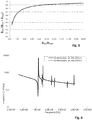
- Fig. 3 shows a graph that illustrates the influence of the ratio between the actuator compliance and the total compliance on the energy efficiency of the inkjet print head.
- the horizontal axis of the graph represents the ratio of the actuator compliance and the fluid channel compliance.
- the vertical axis represents the ratio of the actuator compliance and the total system compliance, which is a factor in the energy coupling coefficient as indicated in Eq. 1. This factor should be selected to be high.
- the ratio of the actuator compliance and the total system compliance is smaller than 0,5 and when the actuator compliance is equal to the fluid channel compliance, the ratio of the actuator compliance and the total system compliance is 0,5.
- the ratio between the actuator compliance and the total system compliance increases to 0,67, which amounts to an energy coupling coefficient improvement of 33% compared to the case where the actuator compliance and the fluid channel compliance are equal.
- a ratio of the actuator compliance over the fluid channel compliance of 10 results in an improvement of only 9% as compared to a ratio of 5.
- a ratio of the actuator compliance over the fluid channel compliance may be effectively selected to be in range of about 2 to about 10 and preferably in a range of about 3 to about 5.
- the actuator compliance B act is relatively large and thus has a strong impact on the operation of an actual inkjet print head if the actual actuator compliance B act deviates from a designed and desired actuator compliance B' act it is desired to be able to accurately control the manufacturing of the inkjet print head, in particular the actuator 5.
- the actuator 5 in accordance with common and cost-effective methods and verifying the resulting actuator compliance B act is a suitable method for manufacturing.
- a method of manufacturing an inkjet print head in accordance with the present invention thus includes determining the actuator compliance B act .
- the step of determining the actuator compliance B act includes a step of performing impedance spectroscopy on a relevant part of the piezo-actuated inkjet print head to obtain an impedance spectrum of the actuator; and deriving from the impedance spectrum the actual actuator compliance. The actual actuator compliance may then be compared to the desired actuator compliance.
- the impedance spectroscopy is a simple electrical measurement on the actuator. So, the measurement may be performed even before the actuator is adhered to other parts of the print head, depending on the specific method of manufacturing the print head.
- Fig. 4 illustrates two exemplary graphs of such an impedance spectrum. It is remarked that the illustrated impedance spectra result from a mathematical simulation.
- a first graph is shown with a solid line and relates to a piezo actuator having a membrane that is 5 micron in thickness, has an effective length of 750 micron and an effective width of 144 micron.
- a second graph is shown with a dashed line and relates to a piezo actuator having a membrane that is 6 micron in thickness, has an effective length of 750 micron and an effective width of 160 micron.
- the effective length and the effective width of the membrane are the length and width used in the mathematical model to represent the flexible wall part of the membrane, i.e. the functional part of the membrane.
- the actual length and width may be slightly different depending on, amongst other aspects, the stiffness of the clamping of the membrane between the supply layer and the output layer.
- the membrane layer and the output layer such adhesive might be flexible such that the membrane may bend beyond a boundary of the pressure chamber.
- the effective length and the effective width may be larger than the actual length and the actual width of the pressure chamber, respectively.
- the first graph shows further resonance frequencies at 1.73 MHz, 2.10 MHz and 2.72 MHz.
- the second graph shows further resonance frequencies at 1.76 MHz, 2.22 MHz and 2.98 MHz.
- These resonance frequencies allow to determine the actuator compliance.
- the actuator properties define the resonance frequencies, taking other parameters of the actuator design as having a predetermined value, it is enabled to determine the actuator compliance from the resonance frequencies. Such method, of course, is only feasible if it is presumed that the other actuator properties have an actual value that is close to the presumed value. In another embodiment, it is considered to determine a value of one or more of such other actuator properties.
- the former provides a mathematical equation describing the impedance spectrum based on properties of the piezo material. Based on the mathematical equation, it appears that the actuator may be defined by three parameters and such three parameters are derivable from a measured impedance spectrum.
- the terms and phrases used herein are not intended to be limiting; but rather, to provide an understandable description of the invention.
- the terms "a” or “an”, as used herein, are defined as one or more than one.
- the term plurality, as used herein, is defined as two or more than two.
- the term another, as used herein, is defined as at least a second or more.
- the terms including and/or having, as used herein, are defined as comprising (i.e., open language).
- the term coupled, as used herein, is defined as connected, although not necessarily directly.
Landscapes
- Engineering & Computer Science (AREA)
- Manufacturing & Machinery (AREA)
- Particle Formation And Scattering Control In Inkjet Printers (AREA)
Claims (5)
- Tête d'impression à jet d'encre (1) pour expulser une gouttelette d'un fluide au travers d'un orifice de buse, la tête d'impression à jet d'encre (1) comprenant :• un canal de fluide pour contenir une quantité de canal de fluide, le canal de fluide comprenant une chambre de pression (3) en communication de fluide avec l'orifice de buse ;• un actionneur piézoélectrique (5) comprenant∘ un empilement piézoélectrique actif, comprenant une première électrode (51), une seconde électrode (53), et une couche de piézo-matériau (52) agencée entre la première et la seconde électrode (51, 53) ;∘ une membrane (54) présentant un premier côté et un second côté, le second côté étant opposé au premier côté,∘ dans laquelle l'empilement piézoélectrique actif est prévu sur le premier côté de la membrane (54) et la chambre de pression (3) sur le second côté de la membrane (54) de sorte que la membrane (54) forme une paroi flexible de la chambre de pression (3), et∘ dans laquelle l'actionneur piézoélectrique (5) est agencé sur la membrane (54) pour se déformer par pliage suite à l'application d'une tension sur la première électrode (51) et la seconde électrode (53) ;dans laquelle∘ l'actionneur piézoélectrique (5) présente une élasticité d'actionneur ;∘ le canal de fluide, lorsqu'il contient la quantité de canal de fluide, présente une élasticité de canal de fluide,∘ l'élasticité de canal de fluide et l'élasticité d'actionneur forment ensemble une élasticité de système total qui correspond à toutes les élasticités de la tête d'impression à jet d'encre (1), et∘ l'élasticité d'actionneur est supérieure à deux fois l'élasticité de canal de fluide.
- Tête d'impression à jet d'encre (1) selon la revendication 1, dans laquelle l'élasticité d'actionneur est supérieure à cinq fois l'élasticité de canal de fluide.
- Procédé de conception d'une tête d'impression à jet d'encre à actionneur piézoélectrique (1), dans lequel l'actionneur piézoélectrique (5) comprend :∘ un empilement piézoélectrique actif, comprenant une première électrode (51), une seconde électrode (53), et une couche de piézo-matériau (52) agencée entre la première et la seconde électrode (51, 53) ;∘ une membrane (54) présentant un premier côté et un second côté, le second côté étant opposé au premier côté,∘ dans laquelle l'empilement piézoélectrique actif est prévu sur le premier côté de la membrane (54) et une chambre de pression (3) sur le second côté de la membrane (54) de sorte que la membrane (54) forme une paroi flexible de la chambre de pression (3), et∘ dans laquelle l'actionneur piézoélectrique (5) est agencé sur la membrane (54) pour se déformer par pliage suite à l'application d'une tension sur la première électrode (51) et la seconde électrode (53) ;dans lequel le procédé comprend :∘ la sélection d'une conception acoustique, la conception acoustique incluant un déplacement de volume déchargé de l'actionneur piézoélectrique (5) en réponse à une tension d'entraînement et une élasticité de système total, qui correspond à toutes les élasticités de la tête d'impression à jet d'encre (1) ;∘ la sélection d'une élasticité d'actionneur et d'une élasticité de canal de fluide, l'élasticité d'actionneur correspondant à une élasticité de l'actionneur piézoélectrique (5) et l'élasticité de canal de fluide correspondant à une élasticité d'un canal de fluide, lorsqu'il contient une quantité de canal de fluide, l'élasticité d'actionneur et l'élasticité de canal de fluide formant ensemble l'élasticité de système total ;
dans lequel l'élasticité d'actionneur est sélectionnée de sorte à être supérieure à deux fois l'élasticité de canal de fluide. - Procédé selon la revendication 3, dans lequel l'élasticité d'actionneur est sélectionnée de sorte à être supérieure à cinq fois l'élasticité de canal de fluide.
- Procédé de fabrication d'une tête d'impression à actionneur piézoélectrique (1) ayant été conçue pour présenter une élasticité d'actionneur souhaitée, dans lequel le procédé comprend les étapes de• fabrication d'au moins une partie d'une tête d'impression à jet d'encre à actionneur piézoélectrique (1) selon la revendication 1 ou 2, dans lequel ladite partie inclut au moins l'actionneur piézoélectrique (5), l'actionneur piézoélectrique comprenant un empilement piézoélectrique actif, comprenant∘ une première électrode (51), une seconde électrode (52), et une couche de piézo-matériau (52) agencée entre la première et la seconde électrode (51, 53) ;∘ une membrane (54), l'empilement piézoélectrique actif étant prévu sur un premier côté de la membrane (54) ;• réalisation d'une spectroscopie d'impédance sur la partie de la tête d'impression à jet d'encre à actionneur piézoélectrique (1) pour obtenir un spectre d'impédance ;• dérivation à partir du spectre d'impédance d'une élasticité d'actionneur réelle ; et• comparaison de l'élasticité d'actionneur réelle avec l'élasticité d'actionneur souhaitée.
Priority Applications (1)
| Application Number | Priority Date | Filing Date | Title |
|---|---|---|---|
| EP14744491.3A EP3024658B1 (fr) | 2013-07-23 | 2014-07-16 | Tête d'impression à jet d'encre à commande piézo-électrique, procédé de conception d'une telle tête d'impression et procédé de fabrication d'une telle tête d'impression |
Applications Claiming Priority (3)
| Application Number | Priority Date | Filing Date | Title |
|---|---|---|---|
| EP13177581 | 2013-07-23 | ||
| EP14744491.3A EP3024658B1 (fr) | 2013-07-23 | 2014-07-16 | Tête d'impression à jet d'encre à commande piézo-électrique, procédé de conception d'une telle tête d'impression et procédé de fabrication d'une telle tête d'impression |
| PCT/EP2014/065230 WO2015010985A1 (fr) | 2013-07-23 | 2014-07-16 | Tête d'impression à jet d'encre à commande piézo-électrique, procédé de conception d'une telle tête d'impression et procédé de fabrication d'une telle tête d'impression |
Publications (2)
| Publication Number | Publication Date |
|---|---|
| EP3024658A1 EP3024658A1 (fr) | 2016-06-01 |
| EP3024658B1 true EP3024658B1 (fr) | 2019-06-05 |
Family
ID=48808247
Family Applications (1)
| Application Number | Title | Priority Date | Filing Date |
|---|---|---|---|
| EP14744491.3A Active EP3024658B1 (fr) | 2013-07-23 | 2014-07-16 | Tête d'impression à jet d'encre à commande piézo-électrique, procédé de conception d'une telle tête d'impression et procédé de fabrication d'une telle tête d'impression |
Country Status (3)
| Country | Link |
|---|---|
| US (1) | US20160121611A1 (fr) |
| EP (1) | EP3024658B1 (fr) |
| WO (1) | WO2015010985A1 (fr) |
Families Citing this family (6)
| Publication number | Priority date | Publication date | Assignee | Title |
|---|---|---|---|---|
| JP6828283B2 (ja) * | 2016-06-22 | 2021-02-10 | セイコーエプソン株式会社 | 画像記録方法およびインクジェットインク組成物 |
| EP3275662B8 (fr) | 2016-07-28 | 2021-01-20 | Canon Production Printing Holding B.V. | Procédé de fabrication d'une tête d'impression à jet d'encre |
| JP6844302B2 (ja) * | 2017-02-22 | 2021-03-17 | セイコーエプソン株式会社 | インクジェット記録方法およびインクジェット記録装置の制御方法 |
| US10712376B2 (en) * | 2018-03-29 | 2020-07-14 | Xerox Corporation | Impedance measurement of individual actuators of a piezoelectric print head |
| JP7599481B2 (ja) * | 2020-03-30 | 2024-12-13 | 京セラ株式会社 | 液体吐出ヘッド及び記録装置 |
| JP7474644B2 (ja) * | 2020-06-18 | 2024-04-25 | 株式会社日立ハイテク | 自動化学分析装置および電気インピーダンススペクトル測定器 |
Family Cites Families (5)
| Publication number | Priority date | Publication date | Assignee | Title |
|---|---|---|---|---|
| JP3503386B2 (ja) * | 1996-01-26 | 2004-03-02 | セイコーエプソン株式会社 | インクジェット式記録ヘッド及びその製造方法 |
| JP2003053966A (ja) * | 2000-06-12 | 2003-02-26 | Seiko Epson Corp | インクジェット式記録ヘッド |
| JP2003011362A (ja) * | 2001-06-29 | 2003-01-15 | Toshiba Tec Corp | インクジェットプリンタおよびインクジェットヘッドの駆動方法 |
| JP2004017612A (ja) | 2002-06-20 | 2004-01-22 | Seiko Epson Corp | 液体噴射ヘッド及び液体噴射装置 |
| JP2007049025A (ja) * | 2005-08-11 | 2007-02-22 | Seiko Epson Corp | アクチュエータ装置及び液体噴射ヘッド並びに液体噴射装置 |
-
2014
- 2014-07-16 EP EP14744491.3A patent/EP3024658B1/fr active Active
- 2014-07-16 WO PCT/EP2014/065230 patent/WO2015010985A1/fr not_active Ceased
-
2016
- 2016-01-08 US US14/991,430 patent/US20160121611A1/en not_active Abandoned
Non-Patent Citations (1)
| Title |
|---|
| None * |
Also Published As
| Publication number | Publication date |
|---|---|
| EP3024658A1 (fr) | 2016-06-01 |
| WO2015010985A1 (fr) | 2015-01-29 |
| US20160121611A1 (en) | 2016-05-05 |
Similar Documents
| Publication | Publication Date | Title |
|---|---|---|
| EP3024658B1 (fr) | Tête d'impression à jet d'encre à commande piézo-électrique, procédé de conception d'une telle tête d'impression et procédé de fabrication d'une telle tête d'impression | |
| US6676238B2 (en) | Driving method and apparatus for liquid discharge head | |
| CN107825853B (zh) | 喷墨头驱动装置以及喷墨头驱动方法 | |
| US10239313B2 (en) | Inkjet head drive apparatus | |
| CN107297952A (zh) | 喷墨打印头驱动装置 | |
| KR19980063513A (ko) | 잉크젯 헤드 | |
| JP2016185685A (ja) | インクジェットヘッド駆動装置 | |
| US10780693B2 (en) | Inkjet head | |
| EP3275662B1 (fr) | Procédé de fabrication d'une tête d'impression à jet d'encre | |
| JPH09141851A (ja) | アクチュエータの駆動方法およびインクジェット記録装置 | |
| EP3083486B1 (fr) | Puce mems et procédé de fabrication d'une puce mems | |
| JP3693939B2 (ja) | セル駆動型マイクロポンプ部材及び製造方法 | |
| CN1820950A (zh) | 喷墨记录装置 | |
| US9682555B2 (en) | Inkjet print head with improved lifetime and efficiency | |
| JP2003008095A (ja) | 圧電アクチュエータおよび液滴噴射装置 | |
| JPWO2009107552A1 (ja) | インクジェットヘッド及びその駆動方法 | |
| EP0963843A2 (fr) | Dispositif d'éjection d'encre utilisant des ondes de Lamb et méthode de fabrication de ce dispositif | |
| Mawatari et al. | Development of New Inkjet Head Applying MEMS Technology and Thin Film Actuator. | |
| JP2008023837A (ja) | 液滴吐出装置 | |
| US10179451B2 (en) | Liquid ejection head and ink jet printer | |
| WO2023233861A1 (fr) | Tête à jet d'encre | |
| Rumschoettel et al. | Compact Model for the Static and Dynamic Behavior of a Piezoelectric Bimorph Actuator for Microfluidic MEMS | |
| JP4187776B1 (ja) | インクジェットヘッドの接着不良判定方法、インクジェットヘッドの製造方法、および、画像形成装置の製造方法 | |
| JP2009016819A (ja) | 圧電アクチュエータのポーリング方法 | |
| JP2005212309A (ja) | インクジェットヘッド及びそれを用いた液滴吐出装置 |
Legal Events
| Date | Code | Title | Description |
|---|---|---|---|
| PUAI | Public reference made under article 153(3) epc to a published international application that has entered the european phase |
Free format text: ORIGINAL CODE: 0009012 |
|
| 17P | Request for examination filed |
Effective date: 20160223 |
|
| AK | Designated contracting states |
Kind code of ref document: A1 Designated state(s): AL AT BE BG CH CY CZ DE DK EE ES FI FR GB GR HR HU IE IS IT LI LT LU LV MC MK MT NL NO PL PT RO RS SE SI SK SM TR |
|
| AX | Request for extension of the european patent |
Extension state: BA ME |
|
| DAX | Request for extension of the european patent (deleted) | ||
| STAA | Information on the status of an ep patent application or granted ep patent |
Free format text: STATUS: EXAMINATION IS IN PROGRESS |
|
| 17Q | First examination report despatched |
Effective date: 20180312 |
|
| GRAP | Despatch of communication of intention to grant a patent |
Free format text: ORIGINAL CODE: EPIDOSNIGR1 |
|
| STAA | Information on the status of an ep patent application or granted ep patent |
Free format text: STATUS: GRANT OF PATENT IS INTENDED |
|
| GRAJ | Information related to disapproval of communication of intention to grant by the applicant or resumption of examination proceedings by the epo deleted |
Free format text: ORIGINAL CODE: EPIDOSDIGR1 |
|
| STAA | Information on the status of an ep patent application or granted ep patent |
Free format text: STATUS: EXAMINATION IS IN PROGRESS |
|
| INTG | Intention to grant announced |
Effective date: 20181205 |
|
| GRAP | Despatch of communication of intention to grant a patent |
Free format text: ORIGINAL CODE: EPIDOSNIGR1 |
|
| STAA | Information on the status of an ep patent application or granted ep patent |
Free format text: STATUS: GRANT OF PATENT IS INTENDED |
|
| INTG | Intention to grant announced |
Effective date: 20190107 |
|
| GRAS | Grant fee paid |
Free format text: ORIGINAL CODE: EPIDOSNIGR3 |
|
| GRAA | (expected) grant |
Free format text: ORIGINAL CODE: 0009210 |
|
| STAA | Information on the status of an ep patent application or granted ep patent |
Free format text: STATUS: THE PATENT HAS BEEN GRANTED |
|
| AK | Designated contracting states |
Kind code of ref document: B1 Designated state(s): AL AT BE BG CH CY CZ DE DK EE ES FI FR GB GR HR HU IE IS IT LI LT LU LV MC MK MT NL NO PL PT RO RS SE SI SK SM TR |
|
| REG | Reference to a national code |
Ref country code: GB Ref legal event code: FG4D |
|
| REG | Reference to a national code |
Ref country code: CH Ref legal event code: EP |
|
| REG | Reference to a national code |
Ref country code: AT Ref legal event code: REF Ref document number: 1139587 Country of ref document: AT Kind code of ref document: T Effective date: 20190615 |
|
| REG | Reference to a national code |
Ref country code: IE Ref legal event code: FG4D |
|
| REG | Reference to a national code |
Ref country code: DE Ref legal event code: R096 Ref document number: 602014047848 Country of ref document: DE |
|
| REG | Reference to a national code |
Ref country code: NL Ref legal event code: FP |
|
| REG | Reference to a national code |
Ref country code: LT Ref legal event code: MG4D |
|
| PG25 | Lapsed in a contracting state [announced via postgrant information from national office to epo] |
Ref country code: AL Free format text: LAPSE BECAUSE OF FAILURE TO SUBMIT A TRANSLATION OF THE DESCRIPTION OR TO PAY THE FEE WITHIN THE PRESCRIBED TIME-LIMIT Effective date: 20190605 Ref country code: ES Free format text: LAPSE BECAUSE OF FAILURE TO SUBMIT A TRANSLATION OF THE DESCRIPTION OR TO PAY THE FEE WITHIN THE PRESCRIBED TIME-LIMIT Effective date: 20190605 Ref country code: LT Free format text: LAPSE BECAUSE OF FAILURE TO SUBMIT A TRANSLATION OF THE DESCRIPTION OR TO PAY THE FEE WITHIN THE PRESCRIBED TIME-LIMIT Effective date: 20190605 Ref country code: FI Free format text: LAPSE BECAUSE OF FAILURE TO SUBMIT A TRANSLATION OF THE DESCRIPTION OR TO PAY THE FEE WITHIN THE PRESCRIBED TIME-LIMIT Effective date: 20190605 Ref country code: NO Free format text: LAPSE BECAUSE OF FAILURE TO SUBMIT A TRANSLATION OF THE DESCRIPTION OR TO PAY THE FEE WITHIN THE PRESCRIBED TIME-LIMIT Effective date: 20190905 Ref country code: SE Free format text: LAPSE BECAUSE OF FAILURE TO SUBMIT A TRANSLATION OF THE DESCRIPTION OR TO PAY THE FEE WITHIN THE PRESCRIBED TIME-LIMIT Effective date: 20190605 Ref country code: HR Free format text: LAPSE BECAUSE OF FAILURE TO SUBMIT A TRANSLATION OF THE DESCRIPTION OR TO PAY THE FEE WITHIN THE PRESCRIBED TIME-LIMIT Effective date: 20190605 |
|
| PG25 | Lapsed in a contracting state [announced via postgrant information from national office to epo] |
Ref country code: LV Free format text: LAPSE BECAUSE OF FAILURE TO SUBMIT A TRANSLATION OF THE DESCRIPTION OR TO PAY THE FEE WITHIN THE PRESCRIBED TIME-LIMIT Effective date: 20190605 Ref country code: BG Free format text: LAPSE BECAUSE OF FAILURE TO SUBMIT A TRANSLATION OF THE DESCRIPTION OR TO PAY THE FEE WITHIN THE PRESCRIBED TIME-LIMIT Effective date: 20190905 Ref country code: GR Free format text: LAPSE BECAUSE OF FAILURE TO SUBMIT A TRANSLATION OF THE DESCRIPTION OR TO PAY THE FEE WITHIN THE PRESCRIBED TIME-LIMIT Effective date: 20190906 Ref country code: RS Free format text: LAPSE BECAUSE OF FAILURE TO SUBMIT A TRANSLATION OF THE DESCRIPTION OR TO PAY THE FEE WITHIN THE PRESCRIBED TIME-LIMIT Effective date: 20190605 |
|
| REG | Reference to a national code |
Ref country code: AT Ref legal event code: MK05 Ref document number: 1139587 Country of ref document: AT Kind code of ref document: T Effective date: 20190605 |
|
| PG25 | Lapsed in a contracting state [announced via postgrant information from national office to epo] |
Ref country code: PT Free format text: LAPSE BECAUSE OF FAILURE TO SUBMIT A TRANSLATION OF THE DESCRIPTION OR TO PAY THE FEE WITHIN THE PRESCRIBED TIME-LIMIT Effective date: 20191007 Ref country code: RO Free format text: LAPSE BECAUSE OF FAILURE TO SUBMIT A TRANSLATION OF THE DESCRIPTION OR TO PAY THE FEE WITHIN THE PRESCRIBED TIME-LIMIT Effective date: 20190605 Ref country code: AT Free format text: LAPSE BECAUSE OF FAILURE TO SUBMIT A TRANSLATION OF THE DESCRIPTION OR TO PAY THE FEE WITHIN THE PRESCRIBED TIME-LIMIT Effective date: 20190605 Ref country code: CZ Free format text: LAPSE BECAUSE OF FAILURE TO SUBMIT A TRANSLATION OF THE DESCRIPTION OR TO PAY THE FEE WITHIN THE PRESCRIBED TIME-LIMIT Effective date: 20190605 Ref country code: EE Free format text: LAPSE BECAUSE OF FAILURE TO SUBMIT A TRANSLATION OF THE DESCRIPTION OR TO PAY THE FEE WITHIN THE PRESCRIBED TIME-LIMIT Effective date: 20190605 Ref country code: SK Free format text: LAPSE BECAUSE OF FAILURE TO SUBMIT A TRANSLATION OF THE DESCRIPTION OR TO PAY THE FEE WITHIN THE PRESCRIBED TIME-LIMIT Effective date: 20190605 |
|
| PG25 | Lapsed in a contracting state [announced via postgrant information from national office to epo] |
Ref country code: IT Free format text: LAPSE BECAUSE OF FAILURE TO SUBMIT A TRANSLATION OF THE DESCRIPTION OR TO PAY THE FEE WITHIN THE PRESCRIBED TIME-LIMIT Effective date: 20190605 Ref country code: IS Free format text: LAPSE BECAUSE OF FAILURE TO SUBMIT A TRANSLATION OF THE DESCRIPTION OR TO PAY THE FEE WITHIN THE PRESCRIBED TIME-LIMIT Effective date: 20191005 Ref country code: SM Free format text: LAPSE BECAUSE OF FAILURE TO SUBMIT A TRANSLATION OF THE DESCRIPTION OR TO PAY THE FEE WITHIN THE PRESCRIBED TIME-LIMIT Effective date: 20190605 |
|
| REG | Reference to a national code |
Ref country code: CH Ref legal event code: PL |
|
| REG | Reference to a national code |
Ref country code: DE Ref legal event code: R097 Ref document number: 602014047848 Country of ref document: DE |
|
| PG25 | Lapsed in a contracting state [announced via postgrant information from national office to epo] |
Ref country code: TR Free format text: LAPSE BECAUSE OF FAILURE TO SUBMIT A TRANSLATION OF THE DESCRIPTION OR TO PAY THE FEE WITHIN THE PRESCRIBED TIME-LIMIT Effective date: 20190605 Ref country code: MC Free format text: LAPSE BECAUSE OF FAILURE TO SUBMIT A TRANSLATION OF THE DESCRIPTION OR TO PAY THE FEE WITHIN THE PRESCRIBED TIME-LIMIT Effective date: 20190605 |
|
| PLBE | No opposition filed within time limit |
Free format text: ORIGINAL CODE: 0009261 |
|
| STAA | Information on the status of an ep patent application or granted ep patent |
Free format text: STATUS: NO OPPOSITION FILED WITHIN TIME LIMIT |
|
| REG | Reference to a national code |
Ref country code: BE Ref legal event code: MM Effective date: 20190731 |
|
| PG25 | Lapsed in a contracting state [announced via postgrant information from national office to epo] |
Ref country code: DK Free format text: LAPSE BECAUSE OF FAILURE TO SUBMIT A TRANSLATION OF THE DESCRIPTION OR TO PAY THE FEE WITHIN THE PRESCRIBED TIME-LIMIT Effective date: 20190605 Ref country code: PL Free format text: LAPSE BECAUSE OF FAILURE TO SUBMIT A TRANSLATION OF THE DESCRIPTION OR TO PAY THE FEE WITHIN THE PRESCRIBED TIME-LIMIT Effective date: 20190605 |
|
| 26N | No opposition filed |
Effective date: 20200306 |
|
| PG25 | Lapsed in a contracting state [announced via postgrant information from national office to epo] |
Ref country code: SI Free format text: LAPSE BECAUSE OF FAILURE TO SUBMIT A TRANSLATION OF THE DESCRIPTION OR TO PAY THE FEE WITHIN THE PRESCRIBED TIME-LIMIT Effective date: 20190605 Ref country code: BE Free format text: LAPSE BECAUSE OF NON-PAYMENT OF DUE FEES Effective date: 20190731 Ref country code: LU Free format text: LAPSE BECAUSE OF NON-PAYMENT OF DUE FEES Effective date: 20190716 Ref country code: LI Free format text: LAPSE BECAUSE OF NON-PAYMENT OF DUE FEES Effective date: 20190731 Ref country code: CH Free format text: LAPSE BECAUSE OF NON-PAYMENT OF DUE FEES Effective date: 20190731 |
|
| PG25 | Lapsed in a contracting state [announced via postgrant information from national office to epo] |
Ref country code: IE Free format text: LAPSE BECAUSE OF NON-PAYMENT OF DUE FEES Effective date: 20190716 |
|
| PG25 | Lapsed in a contracting state [announced via postgrant information from national office to epo] |
Ref country code: CY Free format text: LAPSE BECAUSE OF FAILURE TO SUBMIT A TRANSLATION OF THE DESCRIPTION OR TO PAY THE FEE WITHIN THE PRESCRIBED TIME-LIMIT Effective date: 20190605 |
|
| PG25 | Lapsed in a contracting state [announced via postgrant information from national office to epo] |
Ref country code: HU Free format text: LAPSE BECAUSE OF FAILURE TO SUBMIT A TRANSLATION OF THE DESCRIPTION OR TO PAY THE FEE WITHIN THE PRESCRIBED TIME-LIMIT; INVALID AB INITIO Effective date: 20140716 Ref country code: MT Free format text: LAPSE BECAUSE OF FAILURE TO SUBMIT A TRANSLATION OF THE DESCRIPTION OR TO PAY THE FEE WITHIN THE PRESCRIBED TIME-LIMIT Effective date: 20190605 |
|
| PG25 | Lapsed in a contracting state [announced via postgrant information from national office to epo] |
Ref country code: MK Free format text: LAPSE BECAUSE OF FAILURE TO SUBMIT A TRANSLATION OF THE DESCRIPTION OR TO PAY THE FEE WITHIN THE PRESCRIBED TIME-LIMIT Effective date: 20190605 |
|
| REG | Reference to a national code |
Ref country code: DE Ref legal event code: R081 Ref document number: 602014047848 Country of ref document: DE Owner name: CANON PRODUCTION PRINTING NETHERLANDS B.V., NL Free format text: FORMER OWNER: OCE-TECHNOLOGIES B.V., VENLO, NL Ref country code: DE Ref legal event code: R081 Ref document number: 602014047848 Country of ref document: DE Owner name: CANON KABUSHIKI KAISHA, JP Free format text: FORMER OWNER: OCE-TECHNOLOGIES B.V., VENLO, NL |
|
| PGFP | Annual fee paid to national office [announced via postgrant information from national office to epo] |
Ref country code: GB Payment date: 20250619 Year of fee payment: 12 |
|
| PGFP | Annual fee paid to national office [announced via postgrant information from national office to epo] |
Ref country code: NL Payment date: 20250620 Year of fee payment: 12 |
|
| PGFP | Annual fee paid to national office [announced via postgrant information from national office to epo] |
Ref country code: FR Payment date: 20250620 Year of fee payment: 12 |
|
| PGFP | Annual fee paid to national office [announced via postgrant information from national office to epo] |
Ref country code: DE Payment date: 20250620 Year of fee payment: 12 |
|
| REG | Reference to a national code |
Ref country code: DE Ref legal event code: R081 Ref document number: 602014047848 Country of ref document: DE Owner name: CANON KABUSHIKI KAISHA, JP Free format text: FORMER OWNER: CANON PRODUCTION PRINTING NETHERLANDS B.V., VENLO, NL |