EP3024743B1 - Verpackung und zuschnitt hierfür - Google Patents
Verpackung und zuschnitt hierfür Download PDFInfo
- Publication number
- EP3024743B1 EP3024743B1 EP13741726.7A EP13741726A EP3024743B1 EP 3024743 B1 EP3024743 B1 EP 3024743B1 EP 13741726 A EP13741726 A EP 13741726A EP 3024743 B1 EP3024743 B1 EP 3024743B1
- Authority
- EP
- European Patent Office
- Prior art keywords
- packaging
- flap
- blank
- lid
- dust flap
- Prior art date
- Legal status (The legal status is an assumption and is not a legal conclusion. Google has not performed a legal analysis and makes no representation as to the accuracy of the status listed.)
- Active
Links
Images


Classifications
-
- B—PERFORMING OPERATIONS; TRANSPORTING
- B65—CONVEYING; PACKING; STORING; HANDLING THIN OR FILAMENTARY MATERIAL
- B65D—CONTAINERS FOR STORAGE OR TRANSPORT OF ARTICLES OR MATERIALS, e.g. BAGS, BARRELS, BOTTLES, BOXES, CANS, CARTONS, CRATES, DRUMS, JARS, TANKS, HOPPERS, FORWARDING CONTAINERS; ACCESSORIES, CLOSURES, OR FITTINGS THEREFOR; PACKAGING ELEMENTS; PACKAGES
- B65D5/00—Rigid or semi-rigid containers of polygonal cross-section, e.g. boxes, cartons or trays, formed by folding or erecting one or more blanks made of paper
- B65D5/02—Rigid or semi-rigid containers of polygonal cross-section, e.g. boxes, cartons or trays, formed by folding or erecting one or more blanks made of paper by folding or erecting a single blank to form a tubular body with or without subsequent folding operations, or the addition of separate elements, to close the ends of the body
- B65D5/029—Rigid or semi-rigid containers of polygonal cross-section, e.g. boxes, cartons or trays, formed by folding or erecting one or more blanks made of paper by folding or erecting a single blank to form a tubular body with or without subsequent folding operations, or the addition of separate elements, to close the ends of the body the tubular body presenting a special shape
Definitions
- the present invention relates to a package of cardboard, paper or the like, comprising a front wall and a rear wall, at least two side walls connecting the front and rear walls for forming end faces of the package, the package being in the form of a prismatic body along a longitudinal axis a floor construction comprising at least one hinged to the front or rear wall bottom flap for bottom closure of the package and a lid construction comprising at least one hinged at the front or rear cover flap for lid closure of the packaging, the bottom construction and / or the lid construction at least one comprises a bottom-side and / or lid-side end of at least one front side side wall hinged dust flap.
- the invention further relates to a blank for producing such a package.
- Such packages are known in a wide variety. In particular, such packages are used for filling, transporting and storing packaged or unpackaged free-flowing goods.
- the goods may be, for example, cereals, grain flakes or other pourable and pourable food.
- From the US 2011/111938 A1 and the EP 0 468 860 A1 Cardboard packages and corresponding blanks according to the features of the preambles of claims 1 and 9 are known.
- From the DE 20 2004 011 165 U1 is a powder-tight packaging for powdered goods known.
- the known packaging is formed in the form of a prismatic, octagonal body along a longitudinal axis.
- a disadvantage of such prismatic packaging is that for sealing the lid and / or floor construction in addition to the cover tabs a plurality of dust flaps must be formed.
- a plurality of dust flaps must be formed in the corner areas of the lid and / or floor construction.
- there are also instabilities in pressure loads on these areas for example when storing or stacking these packages one above the other. This can lead to undesirable damage to the packaging.
- a packaging of cardboard, paper or the like comprises a front wall and a rear wall, at least two side walls connecting the front and rear walls for forming end faces of the packaging, the packaging being in the form of a prismatic body along a longitudinal axis, a bottom construction comprising at least one hinged to the front or rear wall bottom flap for bottom closure of the package and a lid construction comprising at least one hinged on the front or rear cover flap for lid closure of the packaging, the bottom construction and / or the lid construction at least one at a bottom and / or lid-side end of at least one front-side side wall hinged dust flap comprises.
- the dust flap is like that designed so that it rests at least partially in a closed position on the side walls or on which it is not hinged.
- the inventive design of the dust flap ensures a secure closure or a secure cover in the area of the lid and / or bottom construction of the packaging. Furthermore, as a result of the at least regionally resting of the dust flap on the side walls or the walls of the packaging, an increased loading stability of the packaging in these areas results. Such packaging can therefore be easily stacked on top of each other, which is necessary, for example, when shipping on pallets. Furthermore, thinner board thicknesses can optionally be used in comparison to previously known packages. This material saving results in significant cost advantages through the packaging according to the invention. Furthermore, the dust flap is designed such that, in addition, in a closed position, it projects beyond at least one side wall, on which it rests, at least in regions.
- the dust flap comprises at least one latching lug, wherein the latching lug is designed such that it rests in the closed position of the dust flap on the bottom and / or cover flap and / or the front wall and / or the rear wall of the packaging. It can be provided that the detent latched in a formed in the bottom and / or cover flap recess. In addition, this recess may be formed in the transition region between the front and / or the rear wall and the corresponding bottom and / or cover flap.
- At least one latching lug which in the closed position of the dust flap at the corresponding areas of the floor and / or cover flap and / or the front wall and / or the rear wall of the packaging, it is ensured that the packaging retains its shape. In particular, this is important in the automatic, automatic straightening and filling of the packaging. Only with dimensionally stable packaging a simple and safe mechanical filling with particular pourable, powdery and / or free-flowing food is guaranteed. The formation of said recess for locking the detent additionally increases the dimensional stability of the packaging.
- the dust flap comprises at least a first section, wherein the first section is articulated on the corresponding front side wall, and is designed such that it covers in the closed position of the dust flap formed by the end side arranged side walls of the base area.
- the dust flap can have at least one second section adjoining the first section, wherein the second section is designed in such a way that, in the closed position of the dust flap, it bears against the inner sides of the front and rear walls.
- a base surface of the packaging formed as a prismatic body is polygonal, in particular six-, eight-, ten- or twelve-sided. Other forms are conceivable.
- a further aspect of the invention relates to a blank for the production of a packaging made of cardboard, paper or the like, comprising front wall, back wall and side wall elements connected via bend lines for forming the package as a prismatic molded body in the folded state of the blank.
- the blank comprises at least one hinged on the front and / or rear wall panel lid and / or bottom flap and at least one hinged on at least one side wall dust flap.
- the dust flap is designed such that it rests at least partially in the folded state of the blank and in a closed position on the one or more side elements on which it is not hinged. A cut formed in this way ensures a secure closure or secure covering of a packaging produced therefrom in the area of the lid and / or bottom construction.
- the blank according to the invention leads to an increased load stability of the packaging produced therefrom in the areas of the lid and / or floor construction.
- the dust flap is designed such that it protrudes at least partially in the folded state of the blank and in a closed position via at least one side element on which it rests.
- the dust flap comprises at least one latching lug, wherein the latching lug is designed such that it in the closed position of the blank on the bottom and / or cover flap and / or the front wall and / or the rear wall in the closed position of the dust flap is applied.
- the latch can latch in the folded state of the blank and in the closed position of the dust flap in a formed in the bottom and / or cover flap recess. This recess can be formed in the transition region between the front and / or rear wall element and the corresponding bottom and / or cover flap.
- the latching nose contributes to the dimensional stability of the packaging formed from the blank.
- the side elements of the blank or the side walls of the packaging produced therefrom press the latching nose in the folded state of the blank against the bottom and / or lid flap and / or the front wall and / or the rear wall of the folded packaging.
- the dimensional stability of the folded packaging is achieved. This can be further increased if the detent latches in said recess.
- the dust flap comprises at least a first portion, wherein the first portion is articulated to the respective end side member and is formed such that it formed in the folded state of the blank and in the closed position of the dust flap formed by the end side arranged side members Covered area of a base of the package.
- This inventive design of the first portion of the dust flap ensures that it reliably covers this area independently of the base area of the packaging in the areas of the dust flap (s).
- the dust flap comprises at least one adjoining the first portion second portion, wherein the second portion is formed such that it in the folded state of the blank and in the closed position of the dust flap on the inner sides of the front and rear wall elements is present.
- This feature of the blank in turn contributes to the dimensional stability of the package produced from the blank.
- the width of the second section is chosen such that abut in the folded state of the blank, the end portions of the second portion respectively on the inner sides of the front and rear wall elements. Furthermore, there is the possibility that the latching lug is formed in the first portion of the dust flap.
- FIG. 1 shows a schematic representation of a package 10, which is used in particular for storage and transport of bulk, powdered and pourable food.
- the package 10 in this case has a front wall 12 and a rear wall 14, which in each case via three side walls 22, 22 ', 22 ", 24, 24', 24" (see also Figures 2 and 3 ) are connected.
- the side walls 22, 22 ', 22 ", 24, 24', 24" form the end faces 16, 18 of the package 10.
- the package 10 is formed in the form of a prismatic body along a longitudinal axis L and an octagonal base 38th having.
- the package 10 also has a bottom construction 20, each having a hinged at the front and rear walls 12, 14 bottom tab 26, 28 for bottom closure of the package 10 (see also FIG.
- the package 10 has a lid construction 30, the lid construction 30 each comprising a lid flap 32, 34 hinged to the front and rear walls 12, 14 for closing the lid on the packaging.
- both the bottom construction 20 as well as the lid construction 30 each have a on the bottom-side and lid-side ends of the end-side side walls 22, 24 hinged dust flaps 36 (see also FIG. 3 ). It can be seen that the dust flaps 36 are articulated on the middle of the three side walls 22, 24 forming the end faces 16, 18.
- the dust flaps 36 each include a first portion 40, wherein the first portion 40 is hinged to the respective end-side side wall 22, 24.
- the first section 40 is adjoined by a second section 42, wherein lateral latching noses 44 are respectively arranged in the transition region between the first section 40 and the second section 42.
- the locking lugs 44 are designed such that they in a closed position of the dust flap 36 (see also FIG. 2 ) can engage in the recesses 46 formed in the bottom and top flaps 26, 28, 32, 34.
- the recesses 46 are each in the Transition region between the front and rear walls 12, 14 and the corresponding bottom and top flaps 26, 28, 32, 34 is formed.
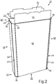
- FIG. 2 shows the package 10 with a closed position of the dust flaps 36 of the lid construction 30.
- the dust flaps 36 are formed such that they rest in the closed position on the side walls 22 ', 22 ", 24', 24".
- the dust flap 36 is not articulated.
- the dust flaps 36 in their closed position project beyond the said side walls 22 ', 22 ", 24', 24" and thus in total extend through the side walls 22, 22 ', 22 ", 24, 24' arranged on the front side, 24 "formed area of the base 38 of the formed as a prismatic body package 10 cover.
- a secure closure or secure covering of this area of the packaging 10 is ensured.
- the load stability of the package 10 increases significantly in this area.
- the dust flaps 36 of the floor construction 20 are identical.
- the second portion 42 of the dust flaps 36 is each formed such that it rests in the closed position of the dust flaps 36 on the inner sides of the front and rear walls 12, 14.
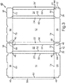
- FIG. 3 shows a schematic representation of a blank 48 of the package 10 according to FIG. 1 .
- the blank 48 includes front wall, back wall and side wall panels 12, 14, 22, 22 ', 22 ", 24, 24', 24" connected via bend lines 50, 52, 54, 56, 60, 62, 64 for forming the package as prismatic Moldings in the folded state of the blank 48 (see FIGS. 1 and 2 ).
- the blank 48 has two lid and bottom flaps 32, 34, 26, 28 hinged to the front and rear wall elements 12, 14.
- a dust flap 36 via bending lines 68, 72, 76, 80 hinged.
- the lid and bottom flaps 32, 34, 26, 28 are connected via corresponding bending lines 66, 70, 74, 78 with the corresponding front and rear wall element 12, 14.
- the blank 48 has an adhesive tab 58, which is connected to the rear wall element 14 via a bending line 82.
- the dust flap 36 is designed so that it rests in the folded state of the blank 48 and in a closed position on the side wall elements 22 ', 22 ", 24', 24", to which it is not articulated (see also FIG. 2 ).
- the dust flap 36 protrudes in the folded state of the blank 48 and in a closed position on the side wall elements 22 ', 22 ", 24', 24", on which it rests out.
- the dust flaps 36 each consist of a first section 40 and an adjoining second section 42. The first portion 40 is hinged to the respective ends of the sidewall members 22, 24.
- the first portion 40 is formed such that it in the folded state of the blank 48 and in the closed position of the dust flap 36 through the end side disposed side wall elements 22, 22 ', 22 ", 24, 24', 24" formed area of a base 38 of Packaging covered.
- the second portion 42 is formed such that it rests in the folded state of the blank 48 and in the closed position of the dust flap 36 on the inner sides of the front and rear wall elements 12, 14. Furthermore one recognizes that in the Transition between the first portion 40 and the second portion 42 each lateral latching lug 44 is formed in the dust flap 36.
- the first portion 40 is approximately trapezoidal in shape
- the second portion 42 is rectangular.
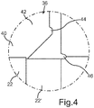
- FIG. 4 shows a schematic detail of the in FIG. 3 shown blank 48.
- a portion of the dust flap 36 is shown. It can be seen that the first portion 40 of the dust flap 36 is articulated on the side wall element 22. In the transition region between the first portion 40 and the second portion 42, the locking lug 44 is formed. In the folded state of the blank 48 and in the closed position of the dust flap 36, the latching nose 44 locks in the recess 46.
- FIG. 5 shows a schematic representation of a blank 48 according to another embodiment. Unlike in the Figures 3 and 4 illustrated first embodiment of the blank 48, this second embodiment has no recesses 46.
- the locking lugs 44 of the dust flaps 36 are shaped differently and lie in the folded state of the blank 48 of the dust flap 36 directly to the corresponding bottom and top flaps 26, 28, 32, 34 at. This concern assists and ensures the dimensional stability of the folded package.
- the further design features correspond to those in the FIG. 3 shown and described.
- the individual elements of the blank 48 according to the second embodiment have been provided with reference numerals corresponding to the description of the in FIG. 3 correspond to the embodiment shown.
- the embodiments of the packaging 10 and the blanks 48 described in the preceding figures serve to illustrate the basic principle of the present invention.
- a variety of differently designed packaging is conceivable.
- the base surfaces 38 of the package 10 formed as a prismatic body not only octagonal but also six-, ten- or twelve-sided. But other forms are possible.
- the above-described packages are designed as folding boxes. Like the associated blanks, they consist in particular of cardboard, paper or comparable materials.
Landscapes
- Engineering & Computer Science (AREA)
- Mechanical Engineering (AREA)
- Cartons (AREA)
- Packaging Of Annular Or Rod-Shaped Articles, Wearing Apparel, Cassettes, Or The Like (AREA)
Description
- Die vorliegende Erfindung betrifft eine Verpackung aus Karton, Papier oder dergleichen, umfassend eine Vorderwand und eine Rückwand, mindestens jeweils zwei die Vorder- und Rückwand verbindende Seitenwände zur Ausbildung von Stirnseiten der Verpackung, wobei die Verpackung in Form eines prismatischen Körpers entlang einer Längsachse ausgebildet ist, eine Bodenkonstruktion umfassend mindestens eine an der Vorder- oder Rückwand angelenkte Bodenlasche zum bodenseitigen Verschluss der Verpackung und eine Deckelkonstruktion umfassend mindestens eine an der Vorder- oder Rückwand angelenkte Deckellasche zum deckelseitigen Verschluss der Verpackung, wobei die Bodenkonstruktion und/oder die Deckelkonstruktion zumindest eine an einem bodenseitigen und/oder deckelseitigen Ende zumindest einer stirnseitigen Seitenwand angelenkte Staublasche umfasst. Die Erfindung betrifft weiterhin einen Zuschnitt zur Herstellung einer derartigen Verpackung.
- Derartige Verpackungen sind in einer großen Vielzahl bekannt. Insbesondere werden derartige Verpackungen für das Abfüllen, den Transport und die Aufbewahrung von verpackten oder unverpackten rieselfähigen Waren verwendet. Bei den Waren kann es sich dabei zum Beispiel um Cerealien, Kornflakes oder andere schütt- und rieselfähige Lebensmittel handeln. Aus der
US 2011/111938 A1 und derEP 0 468 860 A1 sind Kartonverpackungen und entsprechende Zuschnitte gemäß den Merkmalen der Oberbegriffe der Ansprüche 1 und 9 bekannt. Aus derDE 20 2004 011 165 U1 ist eine pulverdichte Verpackung für pulverförmige Waren bekannt. Die bekannte Verpackung ist dabei in Form eines prismatischen, oktogonalen Körpers entlang einer Längsachse ausgebildet. Nachteilig an derartigen prismatisch ausgebildeten Verpackungen ist jedoch, dass zur Abdichtung der Deckel- und/oder Bodenkonstruktion zusätzlich zu den Deckellaschen mehrere Staublaschen ausgebildet sein müssen. Insbesondere in den Eckbereichen der Deckel- und/oder Bodenkonstruktion treten zudem Instabilitäten bei Druckbelastungen dieser Bereiche, zum Beispiel bei der Lagerung oder Stapelung dieser Verpackungen übereinander, auf. Dies kann zu unerwünschten Beschädigungen der Verpackung führen. - Es ist daher die Aufgabe der vorliegenden Erfindung eine gattungsgemäße Verpackung und einen Zuschnitt hierfür bereitzustellen, welche einen sicheren Verschluss beziehungsweise eine sichere Abdeckung im Bereich der Deckel- und/oder Bodenkonstruktion der Verpackung bei gleichzeitiger erhöhter Belastungsstabilität der Verpackung in diesen Bereichen gewährleisten.
- Zur Lösung dieser Aufgaben dient eine gattungsgemäße Faltschachtel gemäß den Merkmalen des Anspruchs 1 sowie ein Zuschnitt gemäß den Merkmalen des Anspruchs 9. Vorteilhafte Ausgestaltungen mit zweckmäßigen Weiterbildungen der Erfindung sind in den jeweiligen abhängigen Ansprüchen angegeben, wobei vorteilhafte Ausgestaltungen der Verpackung als vorteilhafte Ausgestaltungen des Zuschnitts und umgekehrt anzusehen sind.
- Eine erfindungsgemäße Verpackung aus Karton, Papier oder dergleichen, umfasst eine Vorderwand und eine Rückwand, mindestens jeweils zwei die Vorder- und Rückwand verbindende Seitenwände zur Ausbildung von Stirnseiten der Verpackung, wobei die Verpackung in Form eines prismatischen Körpers entlang einer Längsachse ausgebildet ist, eine Bodenkonstruktion umfassend mindestens eine an der Vorder- oder Rückwand angelenkte Bodenlasche zum bodenseitigen Verschluss der Verpackung und eine Deckelkonstruktion umfassend mindestens eine an der Vorder- oder Rückwand angelenkte Deckellasche zum deckelseitigen Verschluss der Verpackung, wobei die Bodenkonstruktion und/oder die Deckelkonstruktion zumindest eine an einem bodenseitigen und/oder deckelseitigen Ende zumindest einer stirnseitigen Seitenwand angelenkte Staublasche umfasst. Dabei ist die Staublasche derart ausgebildet, dass sie in einer Schließstellung an der oder den Seitenwänden, an der oder denen sie nicht angelenkt ist, zumindest bereichsweise aufliegt. Durch die erfindungsgemäße Ausgestaltung der Staublasche ist ein sicherer Verschluss beziehungsweise eine sichere Abdeckung im Bereich der Deckel- und/oder Bodenkonstruktion der Verpackung gewährleistet. Des Weiteren ergibt sich durch das zumindest bereichsweise Aufliegen der Staublasche auf der oder den Seitenwänden der Verpackung eine erhöhte Belastungsstabilität der Verpackung in diesen Bereichen. Derartige Verpackungen können daher problemlos übereinander gestapelt werden, was zum Beispiel bei einem Versenden auf Paletten notwendig ist. Des Weiteren können gegebenenfalls im Vergleich zu bisher bekannten Verpackungen dünnere Kartonstärken verwendet werden. Durch diese Materialeinsparung ergeben sich deutliche Kostenvorteile durch die erfindungsgemäße Verpackung. Des Weiteren ist die Staublasche derart ausgebildet, dass sie zudem in einer Schließstellung über mindestens eine Seitenwand, an der sie aufliegt, zumindest bereichsweise hinausragt. Durch das zumindest teilweise Hinausragen der Staublasche über die Seitenwand und die entsprechende Dimensionierung der Staublasche ist gewährleistet, dass diese einerseits an der Seitenwand aufliegt und andererseits diese sicher überdeckt. Auch eine mögliche seitliche Druckbelastung der erfindungsgemäßen Verpackung im Bereich der Deckel- und/oder Bodenkonstruktion führt nicht dazu, dass die Staublasche aus ihrer Auflage auf der Seitenwand verschoben wird.
- In weiteren vorteilhaften Ausgestaltungen der erfindungsgemäßen Verpackung umfasst die Staublasche mindestens eine Rastnase, wobei die Rastnase derart ausgebildet ist, dass sie in Schließstellung der Staublasche an der Boden- und/oder Deckellasche und/oder der Vorderwand und/oder der Rückwand der Verpackung anliegt. Dabei kann vorgesehen sein, dass die Rastnase in einer in der Boden- und/oder Deckellasche ausgebildeten Ausnehmung verrastet. Zudem kann diese Ausnehmung im Übergangsbereich zwischen der Vorder- und/oder der Rückwand und der entsprechenden Boden- und/oder Deckellasche ausgebildet sein. Durch die Ausbildung mindestens einer Rastnase, die in der Schließstellung der Staublasche an den entsprechenden Bereichen der Boden- und/oder Deckellasche und/oder der Vorderwand und/oder der Rückwand der Verpackung anliegt, ist gewährleistet, dass die Verpackung ihre Form behält. Insbesondere ist dies beim automatischen, maschinellen Aufrichten und Befüllen der Verpackung wichtig. Nur bei formstabilen Verpackungen ist eine einfache und sichere maschinelle Befüllung mit insbesondere schütt-, pulver- und/oder rieselfähigen Lebensmitteln gewährleistet. Die Ausbildung der genannten Ausnehmung zur Verrastung der Rastnase erhöht zusätzlich die Formstabilität der Verpackung.
- In weiteren vorteilhaften Ausgestaltungen der Verpackung umfasst die Staublasche mindestens einen ersten Abschnitt, wobei der erste Abschnitt an der entsprechenden stirnseitigen Seitenwand angelenkt ist, und derart ausgebildet ist, dass er in Schließstellung der Staublasche den durch die stirnseitig angeordneten Seitenwände gebildeten Bereich der Grundfläche überdeckt. Dadurch ist gewährleistet, dass unabhängig von der Grundfläche der prismatisch ausgebildeten Verpackung, die durch die Seitenwände gebildeten Flächen zuverlässig durch den ersten Abschnitt der Staublasche überdeckt und geschlossen werden. Dabei kann die Staublasche mindestens einen sich an den ersten Abschnitt anschließenden zweiten Abschnitt aufweisen, wobei der zweite Abschnitt derart ausgebildet ist, dass er in Schließstellung der Staublasche an den Innenseiten der Vorder- und Rückwand anliegt. Durch das Anliegen des zweiten Abschnitts an den Innenseiten der Vorder- und Rückwand ist der Abstand zwischen der Vorder- und Rückwand eindeutig definiert. Die Innenseiten der Vorder- und Rückwand stützen sich gegen den zweiten Abschnitt der Staublasche ab. Dies trägt zu der erhöhten Formstabilität der erfindungsgemäßen Verpackung bei. Des Weiteren besteht die Möglichkeit, dass die Rastnase in dem ersten Abschnitt ausgebildet ist.
- In weiteren vorteilhaften Ausgestaltungen der erfindungsgemäßen Verpackung ist eine Grundfläche der als prismatischer Körper ausgebildeten Verpackung vieleckig, insbesondere sechs-, acht-, zehn- oder zwölfeckig ausgebildet. Auch andere Formen sind denkbar.
- Ein weiterer Aspekt der Erfindung betrifft einen Zuschnitt für die Herstellung einer Verpackung aus Karton, Papier oder dergleichen, umfassend über Biegelinien verbundene Vorderwand-, Rückwand- und Seitenwandelemente zur Ausbildung der Verpackung als prismatischer Formkörper in gefaltetem Zustand des Zuschnitts. Dabei umfasst der Zuschnitt mindestens eine an dem Vorder- und/oder Rückwandelement angelenkte Deckel- und/oder Bodenlasche und mindestens eine an mindestens einer Seitenwand angelenkte Staublasche. Erfindungsgemäß ist die Staublasche derart ausgebildet, dass sie in gefaltetem Zustand des Zuschnitts und in einer Schließstellung an der oder den Seitenelementen, an dem oder denen sie nicht angelenkt ist, zumindest bereichsweise aufliegt. Ein derartig ausgebildeter Zuschnitt gewährleistet einen sicheren Verschluss beziehungsweise eine sichere Abdeckung einer daraus hergestellten Verpackung im Bereich der Deckel- und/oder Bodenkonstruktion. Zudem führt der erfindungsgemäße Zuschnitt zu einer erhöhten Belastungsstabilität der daraus hergestellten Verpackung in den Bereichen der Deckel- und/oder Bodenkonstruktion. Des Weiteren ist die Staublasche derart ausgebildet, dass sie in gefaltetem Zustand des Zuschnitts und in einer Schließstellung über mindestens ein Seitenelement, an dem sie aufliegt, zumindest bereichsweise hinausragt. Durch eine derartige Ausgestaltung der Staublasche ist wiederum gewährleistet, dass die aus dem Zuschnitt hergestellte Verpackung mittels der Staublasche sicher abgedeckt wird und zudem eine deutlich höhere Formstabilität als vergleichbare bekannte Verpackungen aufweist.
- In weiteren vorteilhaften Ausgestaltungen des erfindungsgemäßen Zuschnitts umfasst die Staublasche mindestens eine Rastnase, wobei die Rastnase derart ausgebildet ist, dass sie in Schließstellung der Staublasche in gefaltetem Zustand des Zuschnitts an der Boden- und/oder Deckellasche und/oder der Vorderwand und/oder der Rückwand anliegt. Dabei kann die Rastnase in gefaltetem Zustand des Zuschnitts und in Schließstellung der Staublasche in einer in der Boden- und/oder Deckellasche ausgebildeten Ausnehmung verrasten. Diese Ausnehmung kann dabei im Übergangsbereich zwischen dem Vorder- und/oder Rückwandelement und der entsprechenden Boden- und/oder Deckellasche ausgebildet sein. In gefaltetem Zustand des Zuschnitts trägt die Rastnase zur Formstabilität der aus dem Zuschnitt gebildeten Verpackung bei. Die Seitenelemente des Zuschnitts beziehungsweise die daraus hergestellten Seitenwände der Verpackung drücken die Rastnase in gefaltetem Zustand des Zuschnitts gegen die Boden- und/oder Deckellasche und/oder die Vorderwand und/oder die Rückwand der gefalteten Verpackung. Durch diese Abstützung wird die Formstabilität der gefalteten Verpackung erzielt. Diese kann noch erhöht werden, wenn die Rastnase in der genannten Ausnehmung verrastet.
- In weiteren vorteilhaften Ausgestaltungen des erfindungsgemäßen Zuschnitts umfasst die Staublasche mindestens einen ersten Abschnitt, wobei der erste Abschnitt an dem entsprechenden stirnseitigen Seitenelement angelenkt ist und derart ausgebildet ist, dass er in gefaltetem Zustand des Zuschnitts und in Schließstellung der Staublasche den durch die stirnseitig angeordneten Seitenelemente gebildeten Bereich einer Grundfläche der Verpackung überdeckt. Durch diese erfindungsgemäße Ausgestaltung des ersten Abschnitts der Staublasche ist gewährleistet, dass dieser unabhängig von der Grundfläche der Verpackung in den Bereichen der Staublasche(n) diesen Bereich zuverlässig überdeckt. Des Weiteren besteht die Möglichkeit, dass die Staublasche mindestens einen sich an den ersten Abschnitt anschließenden zweiten Abschnitt umfasst, wobei der zweite Abschnitt derart ausgebildet ist, dass er in gefaltetem Zustand des Zuschnitts und in Schließstellung der Staublasche an den Innenseiten der Vorder- und Rückwandelemente anliegt. Dieses Merkmal des Zuschnitts trägt wiederum zur Formstabilität der aus dem Zuschnitt hergestellten Verpackung bei. Die Breite des zweiten Abschnitts ist dabei derart gewählt, dass in gefaltetem Zustand des Zuschnitts die Endabschnitte des zweiten Abschnitts jeweils an den Innenseiten der Vorder- und Rückwandelemente anliegen. Des Weiteren besteht die Möglichkeit, dass die Rastnase in dem ersten Abschnitt der Staublasche ausgebildet ist.
- Weitere Merkmale der Erfindung ergeben sich aus den Ansprüchen, den Ausführungsbeispielen sowie anhand der Zeichnungen. Die vorstehend in der Beschreibung genannten Merkmale und Merkmalskombinationen sowie die nachfolgend in den Ausführungsbeispielen genannten Merkmale und Merkmalskombinationen sind nicht nur in der jeweils angegebenen Kombination, sondern auch in anderen Kombinationen verwendbar, ohne den Rahmen der Erfindung zu verlassen. Dabei zeigt:
- Figur 1
- eine schematische Darstellung einer erfindungsgemäßen Verpackung;
- Figur 2
- eine schematische Darstellung der Verpackung gemäß
Figur 1 in teilweise geschlossenem Zustand; - Figur 3
- eine schematische Darstellung eines erfindungsgemäßen Zuschnitts der Verpackung gemäß
Figur 1 ; - Figur 4
- eine schematische Detaildarstellung des in
Figur 3 gezeigten Zuschnitts; und - Figur 5
- eine schematische Darstellung eines erfindungsgemäßen Zuschnitts gemäß einer weiteren Ausführungsform.
-
Figur 1 zeigt eine schematische Darstellung einer Verpackung 10, die insbesondere zur Aufbewahrung und dem Transport von schütt-, pulver- und rieselfähigen Lebensmitteln dient. Die Verpackung 10 weist dabei eine Vorderwand 12 und eine Rückwand 14 auf, die über jeweils drei Seitenwände 22, 22', 22", 24, 24', 24" (siehe auchFiguren 2 und3 ) verbunden sind. Die Seitenwände 22, 22', 22", 24, 24', 24" bilden die Stirnseiten 16, 18 der Verpackung 10. Man erkennt, dass die Verpackung 10 in Form eines prismatischen Körpers entlang einer Längsachse L ausgebildet ist und eine achteckige Grundfläche 38 aufweist. Die Verpackung 10 weist zudem eine Bodenkonstruktion 20 auf, die jeweils eine an der Vorder- und Rückwand 12, 14 angelenkte Bodenlasche 26, 28 zum bodenseitigen Verschluss der Verpackung 10 aufweist (siehe auchFigur 3 ). Des Weiteren weist die Verpackung 10 eine Deckelkonstruktion 30 auf, wobei die Deckelkonstruktion 30 jeweils eine an der Vorder- und Rückwand 12, 14 angelenkte Deckellasche 32, 34 zum deckelseitigen Verschluss der Verpackung umfasst. Zudem weisen in dem dargestellten Ausführungsbeispiel sowohl die Bodenkonstruktion 20 wie auch die Deckelkonstruktion 30 jeweils eine an den bodenseitigen und deckelseitigen Enden der stirnseitigen Seitenwände 22, 24 angelenkte Staublaschen 36 auf (vergleiche auchFigur 3 ). Man erkennt, dass die Staublaschen 36 an der mittleren der drei die Stirnseiten 16, 18 ausbildenden Seitenwände 22, 24 angelenkt sind. - Des Weiteren erkennt man, dass die Staublaschen 36 jeweils einen ersten Abschnitt 40 umfassen, wobei der erste Abschnitt 40 an der entsprechenden stirnseitigen Seitenwand 22, 24 angelenkt ist. An den ersten Abschnitt 40 schließt sich ein zweiter Abschnitt 42 an, wobei im Übergangsbereich zwischen dem ersten Abschnitt 40 und dem zweiten Abschnitt 42 jeweils seitliche Rastnasen 44 angeordnet sind. Die Rastnasen 44 sind derart ausgebildet, dass sie in einer Schließstellung der Staublasche 36 (vergleiche auch
Figur 2 ) in die in den Boden- und Deckellaschen 26, 28, 32, 34 ausgebildeten Ausnehmungen 46 verrasten können. Die Ausnehmungen 46 sind dabei jeweils im Übergangsbereich zwischen der Vorder- und Rückwand 12, 14 und den entsprechenden Boden- und Deckellaschen 26, 28, 32, 34 ausgebildet. -
Figur 2 zeigt die Verpackung 10 mit einer Schließstellung der Staublaschen 36 der Deckelkonstruktion 30. Man erkennt, dass die Staublaschen 36 derart ausgebildet sind, dass sie in der Schließstellung an den Seitenwänden 22', 22", 24', 24" aufliegen. An den Seitenwänden 22', 22", 24', 24" ist die Staublasche 36 nicht angelenkt. Des Weiteren wird deutlich, dass die Staublaschen 36 in ihrer Schließstellung über die genannten Seitenwände 22', 22", 24', 24" hinausragen und somit insgesamt den durch die stirnseitig angeordneten Seitenwände 22, 22', 22", 24, 24', 24" gebildeten Bereich der Grundfläche 38 der als prismatischer Körper ausgebildeten Verpackung 10 überdecken. Damit ist einerseits ein sicherer Verschluss beziehungsweise eine sichere Überdeckung dieses Bereichs der Verpackung 10 gewährleistet. Andererseits erhöht sich die Belastungsstabilität der Verpackung 10 in diesem Bereich deutlich. Die Staublaschen 36 der Bodenkonstruktion 20 sind identisch ausgebildet. - Zudem wird deutlich, dass die Rastnasen 44 in der Schließstellung der Staublasche 36 an den Boden- und Deckellaschen 26, 28, 32, 34 anliegen und in den entsprechenden Ausnehmungen 46 verrasten.
- Man erkennt zudem, dass der zweite Abschnitt 42 der Staublaschen 36 jeweils derart ausgebildet ist, dass er in Schließstellung der Staublaschen 36 an den Innenseiten der Vorder- und Rückwand 12, 14 anliegt. Durch diese Abstützung der Innenseiten der Vorder- und Rückwand 12, 14 ergibt sich eine deutliche Erhöhung der Formstabilität der Verpackung 10.
-
Figur 3 zeigt eine schematische Darstellung eines Zuschnitts 48 der Verpackung 10 gemäßFigur 1 . Der Zuschnitt 48 umfasst über Biegelinien 50, 52, 54, 56, 60, 62, 64 verbundene Vorderwand-, Rückwand- und Seitenwandelemente 12, 14, 22, 22', 22", 24, 24', 24" zur Ausbildung der Verpackung als prismatischer Formkörper in gefaltetem Zustand des Zuschnitts 48 (sieheFiguren 1 und2 ). Man erkennt, dass der Zuschnitt 48 zwei an dem Vorder- und Rückwandelement 12, 14 angelenkte Deckel- und Bodenlaschen 32, 34, 26, 28 aufweist. An den jeweiligen Enden der Seitenwände 22, 24 ist jeweils eine Staublasche 36 über Biegelinien 68, 72, 76, 80 angelenkt. Die Deckel- und Bodenlaschen 32, 34, 26, 28 sind über entsprechende Biegelinien 66, 70, 74, 78 mit dem entsprechenden Vorder- und Rückwandelement 12, 14 verbunden. An dem dem Seitenwandelement 22" gegenüberliegenden Ende weist der Zuschnitt 48 eine Klebelasche 58 auf, die über eine Biegelinie 82 mit dem Rückwandelement 14 verbunden ist. - Des Weiteren erkennt man, dass im Übergangsbereich zwischen dem Vorder- und Rückwandelement 12, 14 und den entsprechenden Boden- und Deckellaschen 26, 28, 32, 34 jeweils eine Ausnehmung 46 ausgebildet ist.
- Die Staublasche 36 ist derart ausgebildet, dass sie in gefaltetem Zustand des Zuschnitts 48 und in einer Schließstellung an den Seitenwandelementen 22', 22", 24', 24", an denen sie nicht angelenkt ist, aufliegt (vergleiche auch
Figur 2 ). Insbesondere ragt die Staublasche 36 in gefaltetem Zustand des Zuschnitts 48 und in einer Schließstellung über die Seitenwandelemente 22', 22", 24', 24", an denen sie aufliegt, hinaus. Man erkennt, dass die Staublaschen 36 jeweils aus einem ersten Abschnitt 40 und einem daran anschließenden zweiten Abschnitt 42 bestehen. Der erste Abschnitt 40 ist an den entsprechenden Enden der Seitenwandelemente 22, 24 angelenkt. Zudem ist der erste Abschnitt 40 derart ausgebildet, dass er in gefaltetem Zustand des Zuschnitts 48 und in Schließstellung der Staublasche 36 den durch die stirnseitig angeordneten Seitenwandelemente 22, 22', 22", 24, 24', 24" gebildeten Bereich einer Grundfläche 38 der Verpackung überdeckt. Der zweite Abschnitt 42 ist derart ausgebildet, dass er in gefaltetem Zustand des Zuschnitts 48 und in Schließstellung der Staublasche 36 an den Innenseiten der Vorder- und Rückwandelemente 12, 14 anliegt. Des Weiteren erkennt man, dass im Übergang zwischen dem ersten Abschnitt 40 und dem zweiten Abschnitt 42 jeweils seitliche eine Rastnase 44 in der Staublasche 36 ausgebildet ist. In dem dargestellten Ausführungsbeispiel ist der erste Abschnitt 40 ungefähr trapezförmig ausgebildet, der zweite Abschnitt 42 ist rechteckig ausgebildet. -
Figur 4 zeigt eine schematische Detaildarstellung des inFigur 3 dargestellten Zuschnitts 48. Insbesondere wird ein Teilbereich der Staublasche 36 dargestellt. Man erkennt, dass der erste Abschnitt 40 der Staublasche 36 an dem Seitenwandelement 22 angelenkt ist. Im Übergangsbereich zwischen dem ersten Abschnitt 40 und dem zweiten Abschnitt 42 ist die Rastnase 44 ausgebildet. In gefaltetem Zustand des Zuschnitts 48 sowie in Schließstellung der Staublasche 36 verrastet die Rastnase 44 in der Ausnehmung 46. -
Figur 5 zeigt eine schematische Darstellung eines Zuschnitts 48 gemäß einer weiteren Ausführungsform. Im Gegensatz zu der in denFiguren 3 und4 dargestellten ersten Ausführungsform des Zuschnitts 48, weist diese zweite Ausführungsform keine Ausnehmungen 46 auf. Die Rastnasen 44 der Staublaschen 36 sind anders geformt und liegen in gefaltetem Zustand des Zuschnitts 48 der Staublasche 36 direkt an den entsprechenden Boden- und Deckellaschen 26, 28, 32, 34 an. Durch dieses Anliegen wird die Formstabilität der gefalteten Verpackung unterstützt und gewährleistet. Die weiteren Ausgestaltungsmerkmale entsprechen den in derFigur 3 gezeigten und beschriebenen. Die einzelnen Elemente des Zuschnitts 48 gemäß der zweiten Ausführungsform wurden mit Bezugszeichen versehen, die der Beschreibung des inFigur 3 gezeigten Ausführungsbeispiels entsprechen. - Die in den vorhergehenden Figuren beschriebenen Ausführungsbeispiele der Verpackungen 10 beziehungsweise der Zuschnitte 48 dienen zur Verdeutlichung des Grundprinzips der vorliegenden Erfindung. Insbesondere ist eine Vielzahl unterschiedlich ausgebildeter Verpackungen denkbar. So können die Grundflächen 38 der als prismatischer Körper ausgebildeten Verpackung 10 nicht nur achteckig sondern auch sechs-, zehn- oder zwölfeckig ausgebildet sein. Aber auch andere Formen sind möglich.
- Die vorhergehenden beschriebenen Verpackungen sind als Faltschachteln ausgebildet. Sie bestehen wie die zugehörigen Zuschnitte insbesondere aus Karton, Papier oder vergleichbaren Materialien.
Claims (15)
- Verpackung aus Karton, Papier oder dergleichen, umfassend- eine Vorderwand (12) und eine Rückwand (14), mindestens jeweils zwei die Vorder- und Rückwand (12, 14) verbindende Seitenwände (22, 22', 22", 24, 24', 24") zur Ausbildung von Stirnseiten (16, 18) der Verpackung (10), wobei die Verpackung (10) in Form eines prismatischen Körpers entlang einer Längsachse (L) ausgebildet ist,- eine Bodenkonstruktion (20) umfassend mindestens eine an der Vorder- oder Rückwand (12, 14) angelenkte Bodenlasche (26, 28) zum bodenseitigen Verschluss der Verpackung (10),- eine Deckelkonstruktion (30) umfassend mindestens eine an der Vorder- oder Rückwand (12, 14) angelenkte Deckellasche (32, 34) zum deckelseitigen Verschluss der Verpackung (10),wobei die Bodenkonstruktion (20) und/oder die Deckelkonstruktion (30) zumindest eine an einem bodenseitigen und/oder deckelseitigen Ende zumindest einer stirnseitigen Seitenwand (22, 24) angelenkte Staublasche (36) umfasst,
dadurch gekennzeichnet,
dass die Staublasche (36) derart ausgebildet ist, dass sie in einer Schließstellung an der oder den Seitenwänden (22', 22", 24', 24"), an der oder denen sie nicht angelenkt ist, zumindest bereichsweise aufliegt und über mindestens eine Seitenwand (22', 22", 24', 24"), an der sie aufliegt, zumindest bereichsweise hinausragt. - Verpackung nach Anspruch 1,
dadurch gekennzeichnet,
dass die Staublasche (36) mindestens eine Rastnase (44) umfasst, wobei die Rastnase (44) derart ausgebildet ist, dass sie in Schließstellung der Staublasche (36) an der Boden- und/oder Deckellasche (26, 28, 32, 34) und/oder der Vorderwand (12) und/oder der Rückwand (14) anliegt. - Verpackung nach Anspruch 2,
dadurch gekennzeichnet,
dass die Rastnase (44) in einer in der Boden- und/oder Deckellasche (26, 28, 32, 34) ausgebildeten Ausnehmung (46) verrastet. - Verpackung nach Anspruch 3,
dadurch gekennzeichnet,
dass die Ausnehmung (46) im Übergangsbereich zwischen der Vorder- und/der Rückwand (12, 14) und der entsprechenden Boden- und/oder Deckellasche (26, 28, 32, 34) ausgebildet ist. - Verpackung nach einem der vorhergehenden Ansprüche,
dadurch gekennzeichnet,
dass die Staublasche (36) mindestens einen ersten Abschnitt (40) umfasst, wobei der erste Abschnitt (40) an der entsprechenden stirnseitigen Seitenwand (22, 24) angelenkt ist und derart ausgebildet ist, dass er in Schließstellung der Staublasche (36) den durch die stirnseitig angeordneten Seitenwände (22, 22', 22", 24, 24', 24") gebildeten Bereich einer Grundfläche (38) der als prismatischer Körper ausgebildeten Verpackung (10) überdeckt. - Verpackung nach Anspruch 5,
dadurch gekennzeichnet,
dass die Staublasche (36) mindestens einen sich an den ersten Abschnitt (40) anschließenden zweiten Abschnitt (42) umfasst, wobei der zweite Abschnitt (42) derart ausgebildet ist, dass er in Schließstellung der Staublasche (36) an den Innenseiten der Vorder- und Rückwand (12, 14) anliegt. - Verpackung nach Anspruch 5 oder 6,
dadurch gekennzeichnet,
dass die Rastnase (44) in dem ersten Abschnitt (40) ausgebildet ist. - Verpackung nach einem der vorhergehenden Ansprüche,
dadurch gekennzeichnet,
dass eine Grundfläche (38) der als prismatischer Körper ausgebildeten Verpackung (10) vieleckig, insbesondere sechs-, acht-, zehn- oder zwölfeckig ausgebildet ist. - Zuschnitt für die Herstellung einer Verpackung aus Karton, Papier oder dergleichen, nach einem der Ansprüche 1-8 umfassend über Biegelinien (50, 52, 54, 56, 60, 62, 64) verbundene Vorderwand-, Rückwand- und Seitenwandelemente (12, 14, 22, 22', 22", 24, 24', 24") zur Ausbildung der Verpackung als prismatischer Formkörper in gefaltetem Zustand des Zuschnitts (48), wobei der Zuschnitt (48) mindestens eine an dem Vorder- und/oder Rückwandelement (12, 14) angelenkte Deckel- und/oder Bodenlasche (32, 34, 26, 28) und mindestens eine an mindestens einem Seitenwandelement (22, 24) angelenkte Staublasche (36) umfasst,
dadurch gekennzeichnet,
dass die Staublasche (36) derart ausgebildet ist, dass sie in gefaltetem Zustand des Zuschnitts (48) und in einer Schließstellung an der oder den Seitenwandelementen (22', 22", 24', 24"), an der oder denen sie nicht angelenkt ist, zumindest bereichsweise aufliegt und über mindestens ein Seitenwandelement (22', 22", 24', 24"), an dem sie aufliegt, zumindest bereichsweise hinausragt. - Zuschnitt nach Anspruch 9,
dadurch gekennzeichnet,
dass die Staublasche (36) mindestens eine Rastnase (44) umfasst, wobei die Rastnase (44) derart ausgebildet ist, dass sie in Schließstellung der Staublasche (36) im gefalteten Zustand des Zuschnitts (48) an der Boden- und/oder Deckellasche (26, 28, 32, 34) und/oder der Vorderwand (12) und/oder der Rückwand (14) anliegt. - Zuschnitt nach Anspruch 10,
dadurch gekennzeichnet,
dass die Rastnase (44) in gefaltetem Zustand des Zuschnitts (48) und in Schließstellung der Staublasche (36) in einer in der Boden- und/oder Deckellasche (26, 28, 32, 34) ausgebildeten Ausnehmung (46) verrastet. - Zuschnitt nach Anspruch 11,
dadurch gekennzeichnet,
dass die Ausnehmung (46) im Übergangsbereich zwischen dem Vorder- und/oder Rückwandelement (12, 14) und der entsprechenden Boden- und/oder Deckellasche (26, 28, 32, 34) ausgebildet ist. - Zuschnitt nach einem der Ansprüche 9 bis 12,
dadurch gekennzeichnet,
dass die Staublasche (36) mindestens einen ersten Abschnitt (40) umfasst, wobei der erste Abschnitt (40) an dem entsprechenden stirnseitigen Seitenwandelement (22, 24) angelenkt ist und derart ausgebildet ist, dass er in gefaltetem Zustand des Zuschnitts (48) und in Schließstellung der Staublasche (36) den durch die stirnseitig angeordneten Seitenelemente (22, 22', 22", 24, 24', 24") gebildeten Bereich einer Grundfläche (38) der Verpackung überdeckt. - Zuschnitt nach Anspruch 13,
dadurch gekennzeichnet,
dass die Staublasche (36) mindestens einen sich an den ersten Abschnitt (40) anschließenden zweiten Abschnitt (42) umfasst, wobei der zweite Abschnitt (42) derart ausgebildet ist, dass er in gefaltetem Zustand des Zuschnitts (48) und in Schließstellung der Staublasche (36) an den Innenseiten der Vorder- und Rückwandelemente (12, 14) anliegt. - Zuschnitt nach Anspruch 13 oder 14,
dadurch gekennzeichnet,
dass die Rastnase (44) in dem ersten Abschnitt (40) der Staublasche (36) ausgebildet ist.
Priority Applications (4)
| Application Number | Priority Date | Filing Date | Title |
|---|---|---|---|
| RS20170818A RS56188B1 (sr) | 2013-07-23 | 2013-07-23 | Ambalaža i izrezak za nju |
| SI201330726T SI3024743T1 (sl) | 2013-07-23 | 2013-07-23 | Embalaža in kroj zanjo |
| HUE13741726A HUE035624T2 (en) | 2013-07-23 | 2013-07-23 | Packaging and cutout for packaging |
| PL13741726T PL3024743T3 (pl) | 2013-07-23 | 2013-07-23 | Opakowanie i wykrój dla niego |
Applications Claiming Priority (1)
| Application Number | Priority Date | Filing Date | Title |
|---|---|---|---|
| PCT/EP2013/065535 WO2015010726A1 (de) | 2013-07-23 | 2013-07-23 | Verpackung und zuschnitt hierfür |
Publications (2)
| Publication Number | Publication Date |
|---|---|
| EP3024743A1 EP3024743A1 (de) | 2016-06-01 |
| EP3024743B1 true EP3024743B1 (de) | 2017-07-05 |
Family
ID=48875029
Family Applications (1)
| Application Number | Title | Priority Date | Filing Date |
|---|---|---|---|
| EP13741726.7A Active EP3024743B1 (de) | 2013-07-23 | 2013-07-23 | Verpackung und zuschnitt hierfür |
Country Status (8)
| Country | Link |
|---|---|
| EP (1) | EP3024743B1 (de) |
| CL (1) | CL2016000131A1 (de) |
| ES (1) | ES2637344T3 (de) |
| HU (1) | HUE035624T2 (de) |
| PL (1) | PL3024743T3 (de) |
| RS (1) | RS56188B1 (de) |
| SI (1) | SI3024743T1 (de) |
| WO (1) | WO2015010726A1 (de) |
Families Citing this family (3)
| Publication number | Priority date | Publication date | Assignee | Title |
|---|---|---|---|---|
| BR112019022217A2 (pt) | 2017-04-28 | 2020-05-12 | Mayr-Melnhof Karton Ag | Embalagem e recorte para a mesma |
| RU2731941C1 (ru) * | 2017-04-28 | 2020-09-09 | Майр-Мельнхоф Картон Аг | Упаковка и заготовка для нее |
| MX2019012767A (es) | 2017-04-28 | 2019-12-05 | Mayr Melnhof Karton Ag | Embalaje y pieza en bruto para el mismo. |
Family Cites Families (3)
| Publication number | Priority date | Publication date | Assignee | Title |
|---|---|---|---|---|
| FR2665137B1 (fr) * | 1990-07-24 | 1994-07-01 | Otor Sa | Caisses en une matiere en feuille, flans et machine pour la realisation de telles caisses. |
| DE202004011165U1 (de) | 2004-07-15 | 2005-12-01 | Henkel Kgaa | Pulverdichte Verpackung |
| US8844797B2 (en) * | 2009-11-11 | 2014-09-30 | Rock-Tenn Shared Services, Llc | Liquid dispensing containers and blanks for making the same |
-
2013
- 2013-07-23 PL PL13741726T patent/PL3024743T3/pl unknown
- 2013-07-23 HU HUE13741726A patent/HUE035624T2/en unknown
- 2013-07-23 EP EP13741726.7A patent/EP3024743B1/de active Active
- 2013-07-23 RS RS20170818A patent/RS56188B1/sr unknown
- 2013-07-23 ES ES13741726.7T patent/ES2637344T3/es active Active
- 2013-07-23 SI SI201330726T patent/SI3024743T1/sl unknown
- 2013-07-23 WO PCT/EP2013/065535 patent/WO2015010726A1/de not_active Ceased
-
2016
- 2016-01-19 CL CL2016000131A patent/CL2016000131A1/es unknown
Also Published As
| Publication number | Publication date |
|---|---|
| RS56188B1 (sr) | 2017-11-30 |
| HUE035624T2 (en) | 2018-05-28 |
| WO2015010726A1 (de) | 2015-01-29 |
| ES2637344T3 (es) | 2017-10-11 |
| SI3024743T1 (sl) | 2017-10-30 |
| CL2016000131A1 (es) | 2016-10-07 |
| EP3024743A1 (de) | 2016-06-01 |
| PL3024743T3 (pl) | 2017-10-31 |
Similar Documents
| Publication | Publication Date | Title |
|---|---|---|
| WO2015010727A1 (de) | Verpackung und zuschnitt hierfür | |
| DE102015001285A1 (de) | Einsatz für eine Versandverpackung, Verpackung damit, Versandverpackung und Zuschnitt dafür | |
| DE202016000073U1 (de) | Verpackung für Schweissverbrauchsmaterial | |
| EP1575835B1 (de) | Verpackungssystem mit tablettenförmigen gegenständen | |
| WO2015010726A1 (de) | Verpackung und zuschnitt hierfür | |
| EP3615437A1 (de) | Verpackung und zuschnitt hierfür | |
| EP4180347B1 (de) | Behälter und zuschnitt zur herstellung eines behälters | |
| EP3009366B1 (de) | Transportbehälter | |
| EP2905242B1 (de) | Packung für Zigaretten | |
| DE4008364C2 (de) | Behälter für Präzisionsteile | |
| EP3615439B1 (de) | Verpackung und zuschnitt hierfür | |
| DE202014007597U1 (de) | Faltschachtel | |
| DE202017104977U1 (de) | Zuschnitt, daraus hergestellte dreidimensionale Struktur und Faltschachtel | |
| EP3615438B1 (de) | Verpackung und zuschnitt hierfür | |
| EP3024744B1 (de) | Verpackung und zuschnitt hierfür | |
| DE202008001304U1 (de) | Faltschachtel mit Aufweitung zur leichten Entnahme großräumiger Güter | |
| DE202012002496U1 (de) | Verpackung und Zuschnitt hierfür | |
| WO2007071539A1 (de) | Faltschachtel mit verstärktem staublaschenbereich | |
| DE102014226580A1 (de) | Verfahren zur Herstellung einer Faltschachtel sowie Gebinde mit einer Faltschachtel | |
| DE202012101401U1 (de) | Faltschachtel und Zuschnitt hierfür | |
| DE102015103048B4 (de) | Faltbarer Verpackungsbehälter sowie Zuschnitt für einen faltbaren Verpackungsbehälter | |
| DE102016118222B4 (de) | Wellpappenverpackung mit Stapelecken | |
| DE202015101805U1 (de) | Transportpalettenabdeckung aus Wellpappe | |
| DE202013102842U1 (de) | Faltschachtel mit Griff | |
| DE102011111821A1 (de) | Faltschachtel und Zuschnittteil zur Herstellung der Faltschachtel |
Legal Events
| Date | Code | Title | Description |
|---|---|---|---|
| PUAI | Public reference made under article 153(3) epc to a published international application that has entered the european phase |
Free format text: ORIGINAL CODE: 0009012 |
|
| 17P | Request for examination filed |
Effective date: 20160112 |
|
| AK | Designated contracting states |
Kind code of ref document: A1 Designated state(s): AL AT BE BG CH CY CZ DE DK EE ES FI FR GB GR HR HU IE IS IT LI LT LU LV MC MK MT NL NO PL PT RO RS SE SI SK SM TR |
|
| AX | Request for extension of the european patent |
Extension state: BA ME |
|
| DAX | Request for extension of the european patent (deleted) | ||
| GRAP | Despatch of communication of intention to grant a patent |
Free format text: ORIGINAL CODE: EPIDOSNIGR1 |
|
| STAA | Information on the status of an ep patent application or granted ep patent |
Free format text: STATUS: GRANT OF PATENT IS INTENDED |
|
| INTG | Intention to grant announced |
Effective date: 20170124 |
|
| GRAS | Grant fee paid |
Free format text: ORIGINAL CODE: EPIDOSNIGR3 |
|
| GRAA | (expected) grant |
Free format text: ORIGINAL CODE: 0009210 |
|
| STAA | Information on the status of an ep patent application or granted ep patent |
Free format text: STATUS: THE PATENT HAS BEEN GRANTED |
|
| AK | Designated contracting states |
Kind code of ref document: B1 Designated state(s): AL AT BE BG CH CY CZ DE DK EE ES FI FR GB GR HR HU IE IS IT LI LT LU LV MC MK MT NL NO PL PT RO RS SE SI SK SM TR |
|
| REG | Reference to a national code |
Ref country code: GB Ref legal event code: FG4D Free format text: NOT ENGLISH |
|
| REG | Reference to a national code |
Ref country code: CH Ref legal event code: EP |
|
| REG | Reference to a national code |
Ref country code: AT Ref legal event code: REF Ref document number: 906415 Country of ref document: AT Kind code of ref document: T Effective date: 20170715 |
|
| REG | Reference to a national code |
Ref country code: IE Ref legal event code: FG4D Free format text: LANGUAGE OF EP DOCUMENT: GERMAN |
|
| REG | Reference to a national code |
Ref country code: RO Ref legal event code: EPE |
|
| REG | Reference to a national code |
Ref country code: DE Ref legal event code: R096 Ref document number: 502013007698 Country of ref document: DE |
|
| REG | Reference to a national code |
Ref country code: FR Ref legal event code: PLFP Year of fee payment: 5 |
|
| REG | Reference to a national code |
Ref country code: NL Ref legal event code: FP |
|
| REG | Reference to a national code |
Ref country code: ES Ref legal event code: FG2A Ref document number: 2637344 Country of ref document: ES Kind code of ref document: T3 Effective date: 20171011 |
|
| REG | Reference to a national code |
Ref country code: LT Ref legal event code: MG4D |
|
| REG | Reference to a national code |
Ref country code: SK Ref legal event code: T3 Ref document number: E 25000 Country of ref document: SK |
|
| PG25 | Lapsed in a contracting state [announced via postgrant information from national office to epo] |
Ref country code: LT Free format text: LAPSE BECAUSE OF FAILURE TO SUBMIT A TRANSLATION OF THE DESCRIPTION OR TO PAY THE FEE WITHIN THE PRESCRIBED TIME-LIMIT Effective date: 20170705 Ref country code: SE Free format text: LAPSE BECAUSE OF FAILURE TO SUBMIT A TRANSLATION OF THE DESCRIPTION OR TO PAY THE FEE WITHIN THE PRESCRIBED TIME-LIMIT Effective date: 20170705 Ref country code: HR Free format text: LAPSE BECAUSE OF FAILURE TO SUBMIT A TRANSLATION OF THE DESCRIPTION OR TO PAY THE FEE WITHIN THE PRESCRIBED TIME-LIMIT Effective date: 20170705 Ref country code: NO Free format text: LAPSE BECAUSE OF FAILURE TO SUBMIT A TRANSLATION OF THE DESCRIPTION OR TO PAY THE FEE WITHIN THE PRESCRIBED TIME-LIMIT Effective date: 20171005 Ref country code: FI Free format text: LAPSE BECAUSE OF FAILURE TO SUBMIT A TRANSLATION OF THE DESCRIPTION OR TO PAY THE FEE WITHIN THE PRESCRIBED TIME-LIMIT Effective date: 20170705 |
|
| PG25 | Lapsed in a contracting state [announced via postgrant information from national office to epo] |
Ref country code: IS Free format text: LAPSE BECAUSE OF FAILURE TO SUBMIT A TRANSLATION OF THE DESCRIPTION OR TO PAY THE FEE WITHIN THE PRESCRIBED TIME-LIMIT Effective date: 20171105 Ref country code: LV Free format text: LAPSE BECAUSE OF FAILURE TO SUBMIT A TRANSLATION OF THE DESCRIPTION OR TO PAY THE FEE WITHIN THE PRESCRIBED TIME-LIMIT Effective date: 20170705 Ref country code: GR Free format text: LAPSE BECAUSE OF FAILURE TO SUBMIT A TRANSLATION OF THE DESCRIPTION OR TO PAY THE FEE WITHIN THE PRESCRIBED TIME-LIMIT Effective date: 20171006 Ref country code: BG Free format text: LAPSE BECAUSE OF FAILURE TO SUBMIT A TRANSLATION OF THE DESCRIPTION OR TO PAY THE FEE WITHIN THE PRESCRIBED TIME-LIMIT Effective date: 20171005 |
|
| REG | Reference to a national code |
Ref country code: DE Ref legal event code: R097 Ref document number: 502013007698 Country of ref document: DE |
|
| REG | Reference to a national code |
Ref country code: IE Ref legal event code: MM4A |
|
| PG25 | Lapsed in a contracting state [announced via postgrant information from national office to epo] |
Ref country code: DK Free format text: LAPSE BECAUSE OF FAILURE TO SUBMIT A TRANSLATION OF THE DESCRIPTION OR TO PAY THE FEE WITHIN THE PRESCRIBED TIME-LIMIT Effective date: 20170705 Ref country code: MC Free format text: LAPSE BECAUSE OF FAILURE TO SUBMIT A TRANSLATION OF THE DESCRIPTION OR TO PAY THE FEE WITHIN THE PRESCRIBED TIME-LIMIT Effective date: 20170705 Ref country code: IE Free format text: LAPSE BECAUSE OF NON-PAYMENT OF DUE FEES Effective date: 20170723 |
|
| PLBE | No opposition filed within time limit |
Free format text: ORIGINAL CODE: 0009261 |
|
| STAA | Information on the status of an ep patent application or granted ep patent |
Free format text: STATUS: NO OPPOSITION FILED WITHIN TIME LIMIT |
|
| REG | Reference to a national code |
Ref country code: HU Ref legal event code: AG4A Ref document number: E035624 Country of ref document: HU |
|
| PG25 | Lapsed in a contracting state [announced via postgrant information from national office to epo] |
Ref country code: EE Free format text: LAPSE BECAUSE OF FAILURE TO SUBMIT A TRANSLATION OF THE DESCRIPTION OR TO PAY THE FEE WITHIN THE PRESCRIBED TIME-LIMIT Effective date: 20170705 Ref country code: SM Free format text: LAPSE BECAUSE OF FAILURE TO SUBMIT A TRANSLATION OF THE DESCRIPTION OR TO PAY THE FEE WITHIN THE PRESCRIBED TIME-LIMIT Effective date: 20170705 |
|
| 26N | No opposition filed |
Effective date: 20180406 |
|
| REG | Reference to a national code |
Ref country code: FR Ref legal event code: PLFP Year of fee payment: 6 |
|
| PG25 | Lapsed in a contracting state [announced via postgrant information from national office to epo] |
Ref country code: MT Free format text: LAPSE BECAUSE OF FAILURE TO SUBMIT A TRANSLATION OF THE DESCRIPTION OR TO PAY THE FEE WITHIN THE PRESCRIBED TIME-LIMIT Effective date: 20170705 |
|
| PG25 | Lapsed in a contracting state [announced via postgrant information from national office to epo] |
Ref country code: CY Free format text: LAPSE BECAUSE OF FAILURE TO SUBMIT A TRANSLATION OF THE DESCRIPTION OR TO PAY THE FEE WITHIN THE PRESCRIBED TIME-LIMIT Effective date: 20170705 |
|
| PG25 | Lapsed in a contracting state [announced via postgrant information from national office to epo] |
Ref country code: MK Free format text: LAPSE BECAUSE OF FAILURE TO SUBMIT A TRANSLATION OF THE DESCRIPTION OR TO PAY THE FEE WITHIN THE PRESCRIBED TIME-LIMIT Effective date: 20170705 |
|
| PG25 | Lapsed in a contracting state [announced via postgrant information from national office to epo] |
Ref country code: PT Free format text: LAPSE BECAUSE OF FAILURE TO SUBMIT A TRANSLATION OF THE DESCRIPTION OR TO PAY THE FEE WITHIN THE PRESCRIBED TIME-LIMIT Effective date: 20170705 |
|
| PG25 | Lapsed in a contracting state [announced via postgrant information from national office to epo] |
Ref country code: AL Free format text: LAPSE BECAUSE OF FAILURE TO SUBMIT A TRANSLATION OF THE DESCRIPTION OR TO PAY THE FEE WITHIN THE PRESCRIBED TIME-LIMIT Effective date: 20170705 |
|
| PGFP | Annual fee paid to national office [announced via postgrant information from national office to epo] |
Ref country code: NL Payment date: 20210721 Year of fee payment: 9 |
|
| PGFP | Annual fee paid to national office [announced via postgrant information from national office to epo] |
Ref country code: LU Payment date: 20210720 Year of fee payment: 9 Ref country code: AT Payment date: 20210720 Year of fee payment: 9 Ref country code: CZ Payment date: 20210713 Year of fee payment: 9 Ref country code: IT Payment date: 20210730 Year of fee payment: 9 |
|
| PGFP | Annual fee paid to national office [announced via postgrant information from national office to epo] |
Ref country code: BE Payment date: 20210721 Year of fee payment: 9 Ref country code: CH Payment date: 20210723 Year of fee payment: 9 Ref country code: HU Payment date: 20210719 Year of fee payment: 9 Ref country code: RO Payment date: 20210712 Year of fee payment: 9 Ref country code: ES Payment date: 20210819 Year of fee payment: 9 Ref country code: SK Payment date: 20210709 Year of fee payment: 9 Ref country code: TR Payment date: 20210713 Year of fee payment: 9 Ref country code: RS Payment date: 20210722 Year of fee payment: 9 Ref country code: SI Payment date: 20210709 Year of fee payment: 9 |
|
| REG | Reference to a national code |
Ref country code: CH Ref legal event code: PL |
|
| REG | Reference to a national code |
Ref country code: NL Ref legal event code: MM Effective date: 20220801 |
|
| REG | Reference to a national code |
Ref country code: SK Ref legal event code: MM4A Ref document number: E 25000 Country of ref document: SK Effective date: 20220723 Ref country code: AT Ref legal event code: MM01 Ref document number: 906415 Country of ref document: AT Kind code of ref document: T Effective date: 20220723 |
|
| REG | Reference to a national code |
Ref country code: BE Ref legal event code: MM Effective date: 20220731 |
|
| PG25 | Lapsed in a contracting state [announced via postgrant information from national office to epo] |
Ref country code: RO Free format text: LAPSE BECAUSE OF NON-PAYMENT OF DUE FEES Effective date: 20220723 Ref country code: LU Free format text: LAPSE BECAUSE OF NON-PAYMENT OF DUE FEES Effective date: 20220723 Ref country code: LI Free format text: LAPSE BECAUSE OF NON-PAYMENT OF DUE FEES Effective date: 20220731 Ref country code: CZ Free format text: LAPSE BECAUSE OF NON-PAYMENT OF DUE FEES Effective date: 20220723 Ref country code: CH Free format text: LAPSE BECAUSE OF NON-PAYMENT OF DUE FEES Effective date: 20220731 Ref country code: AT Free format text: LAPSE BECAUSE OF NON-PAYMENT OF DUE FEES Effective date: 20220723 |
|
| REG | Reference to a national code |
Ref country code: SI Ref legal event code: KO00 Effective date: 20230314 |
|
| PG25 | Lapsed in a contracting state [announced via postgrant information from national office to epo] |
Ref country code: SK Free format text: LAPSE BECAUSE OF NON-PAYMENT OF DUE FEES Effective date: 20220723 Ref country code: SI Free format text: LAPSE BECAUSE OF NON-PAYMENT OF DUE FEES Effective date: 20220724 Ref country code: RS Free format text: LAPSE BECAUSE OF NON-PAYMENT OF DUE FEES Effective date: 20220723 Ref country code: HU Free format text: LAPSE BECAUSE OF NON-PAYMENT OF DUE FEES Effective date: 20220724 Ref country code: BE Free format text: LAPSE BECAUSE OF NON-PAYMENT OF DUE FEES Effective date: 20220731 |
|
| PG25 | Lapsed in a contracting state [announced via postgrant information from national office to epo] |
Ref country code: NL Free format text: LAPSE BECAUSE OF NON-PAYMENT OF DUE FEES Effective date: 20220801 |
|
| PG25 | Lapsed in a contracting state [announced via postgrant information from national office to epo] |
Ref country code: IT Free format text: LAPSE BECAUSE OF NON-PAYMENT OF DUE FEES Effective date: 20220723 |
|
| REG | Reference to a national code |
Ref country code: ES Ref legal event code: FD2A Effective date: 20230901 |
|
| PG25 | Lapsed in a contracting state [announced via postgrant information from national office to epo] |
Ref country code: ES Free format text: LAPSE BECAUSE OF NON-PAYMENT OF DUE FEES Effective date: 20220724 |
|
| P01 | Opt-out of the competence of the unified patent court (upc) registered |
Effective date: 20231006 |
|
| PGFP | Annual fee paid to national office [announced via postgrant information from national office to epo] |
Ref country code: DE Payment date: 20250724 Year of fee payment: 13 |
|
| PGFP | Annual fee paid to national office [announced via postgrant information from national office to epo] |
Ref country code: PL Payment date: 20250710 Year of fee payment: 13 |
|
| PGFP | Annual fee paid to national office [announced via postgrant information from national office to epo] |
Ref country code: GB Payment date: 20250724 Year of fee payment: 13 |
|
| PGFP | Annual fee paid to national office [announced via postgrant information from national office to epo] |
Ref country code: FR Payment date: 20250723 Year of fee payment: 13 |
|
| PG25 | Lapsed in a contracting state [announced via postgrant information from national office to epo] |
Ref country code: TR Free format text: LAPSE BECAUSE OF NON-PAYMENT OF DUE FEES Effective date: 20220723 |