EP3024767B1 - Procédé pour la production de piles grandes de feuilles grand format - Google Patents
Procédé pour la production de piles grandes de feuilles grand format Download PDFInfo
- Publication number
- EP3024767B1 EP3024767B1 EP14741636.6A EP14741636A EP3024767B1 EP 3024767 B1 EP3024767 B1 EP 3024767B1 EP 14741636 A EP14741636 A EP 14741636A EP 3024767 B1 EP3024767 B1 EP 3024767B1
- Authority
- EP
- European Patent Office
- Prior art keywords
- stack
- pallet
- receiving table
- sheets
- adapter
- Prior art date
- Legal status (The legal status is an assumption and is not a legal conclusion. Google has not performed a legal analysis and makes no representation as to the accuracy of the status listed.)
- Active
Links
- 238000004519 manufacturing process Methods 0.000 title claims description 11
- 238000000034 method Methods 0.000 claims description 18
- 230000015572 biosynthetic process Effects 0.000 claims description 9
- 238000003860 storage Methods 0.000 claims description 4
- 238000007599 discharging Methods 0.000 claims 1
- 238000003780 insertion Methods 0.000 claims 1
- 230000037431 insertion Effects 0.000 claims 1
- 238000010923 batch production Methods 0.000 description 2
- 239000011111 cardboard Substances 0.000 description 1
- 239000011087 paperboard Substances 0.000 description 1
Images


Classifications
-
- B—PERFORMING OPERATIONS; TRANSPORTING
- B65—CONVEYING; PACKING; STORING; HANDLING THIN OR FILAMENTARY MATERIAL
- B65H—HANDLING THIN OR FILAMENTARY MATERIAL, e.g. SHEETS, WEBS, CABLES
- B65H31/00—Pile receivers
- B65H31/32—Auxiliary devices for receiving articles during removal of a completed pile
-
- B—PERFORMING OPERATIONS; TRANSPORTING
- B65—CONVEYING; PACKING; STORING; HANDLING THIN OR FILAMENTARY MATERIAL
- B65H—HANDLING THIN OR FILAMENTARY MATERIAL, e.g. SHEETS, WEBS, CABLES
- B65H31/00—Pile receivers
- B65H31/04—Pile receivers with movable end support arranged to recede as pile accumulates
- B65H31/08—Pile receivers with movable end support arranged to recede as pile accumulates the articles being piled one above another
- B65H31/10—Pile receivers with movable end support arranged to recede as pile accumulates the articles being piled one above another and applied at the top of the pile
-
- B—PERFORMING OPERATIONS; TRANSPORTING
- B65—CONVEYING; PACKING; STORING; HANDLING THIN OR FILAMENTARY MATERIAL
- B65G—TRANSPORT OR STORAGE DEVICES, e.g. CONVEYORS FOR LOADING OR TIPPING, SHOP CONVEYOR SYSTEMS OR PNEUMATIC TUBE CONVEYORS
- B65G57/00—Stacking of articles
- B65G57/02—Stacking of articles by adding to the top of the stack
- B65G57/11—Stacking of articles by adding to the top of the stack the articles being stacked by direct action of the feeding conveyor
-
- B—PERFORMING OPERATIONS; TRANSPORTING
- B65—CONVEYING; PACKING; STORING; HANDLING THIN OR FILAMENTARY MATERIAL
- B65H—HANDLING THIN OR FILAMENTARY MATERIAL, e.g. SHEETS, WEBS, CABLES
- B65H2301/00—Handling processes for sheets or webs
- B65H2301/40—Type of handling process
- B65H2301/42—Piling, depiling, handling piles
- B65H2301/422—Handling piles, sets or stacks of articles
- B65H2301/4225—Handling piles, sets or stacks of articles in or on special supports
- B65H2301/42256—Pallets; Skids; Platforms with feet, i.e. handled together with the stack
-
- B—PERFORMING OPERATIONS; TRANSPORTING
- B65—CONVEYING; PACKING; STORING; HANDLING THIN OR FILAMENTARY MATERIAL
- B65H—HANDLING THIN OR FILAMENTARY MATERIAL, e.g. SHEETS, WEBS, CABLES
- B65H2701/00—Handled material; Storage means
- B65H2701/10—Handled articles or webs
- B65H2701/11—Dimensional aspect of article or web
- B65H2701/113—Size
- B65H2701/1131—Size of sheets
- B65H2701/11312—Size of sheets large formats, i.e. above A3
-
- B—PERFORMING OPERATIONS; TRANSPORTING
- B65—CONVEYING; PACKING; STORING; HANDLING THIN OR FILAMENTARY MATERIAL
- B65H—HANDLING THIN OR FILAMENTARY MATERIAL, e.g. SHEETS, WEBS, CABLES
- B65H2701/00—Handled material; Storage means
- B65H2701/10—Handled articles or webs
- B65H2701/17—Nature of material
- B65H2701/176—Cardboard
Definitions
- the invention relates to a method for producing large stacks from large-format sheets, wherein a storage platform is designed as a vertically movable and removable stack receiving table to bridge a vertical distance between a feed plane of the sheets and a corridor level, a conventional pallet being placed on the stack receiving table, on which the sheets are placed in stacks, the receiving table being moved to an upper end position by means of a lifting device and the sheets being fed continuously to the pallet, the stack receiving table being continuously lowered with the pallet during the continuous feeding in order to ensure a uniform stack formation, when, when the desired stack height has been reached, the stack changing device moves between two sheets and completely separates them from one another, the subsequent stack on the upper side of the S tape receiving table is formed, the shelf being continuously lowered while the receiving table moves to its lower end position at the level of the corridor area and the pallet with the stack formed is transported away, after which the stack receiving table is moved to the level of the stack changing device with a new, empty conventional pallet is and the stack changing device moves horizontally back to its starting position and thereby loads
- the invention thus relates in part to a device and a method for stacking sheets, in particular sheets of paper or cardboard fed on flakes on pallets, with a stack-receiving table which can be moved by means of a lifting device and a stack-changing device for dividing the supplied ones Sheets in stacks.
- the storage platform is designed as a vertically retractable and removable stack receiving table in order to bridge the vertical distance between the feeding level of the sheets and the corridor level.
- a pallet is placed on the stacking table on which the sheets are stacked.
- the pick-up table is moved to the upper end position by means of a lifting device and the sheets are continuously fed to the pallet.
- the stack receiving table with the pallet is continuously lowered in order to ensure an even stack formation.
- the stack changing device designed for example as a horizontally movable shelf, moves between two sheets and completely separates them.
- the upper of these two sheets thus forms the top sheet of the stack stacked on the pallet
- the upper of the two separate sheets is the first sheet of the subsequent stack.
- the following stack is formed on the top of the shelf.
- the shelf is also lowered continuously.
- the receiving table moves to its lower end position at the level of the corridor area and the pallet with the stack formed is transported away.
- the stacking table is empty with a new one Pallet moved to the height of the stack changing device.
- the stack changing device moves horizontally back to its starting position and thereby unloads the stack that is being formed onto the empty pallet.
- the pallet or the stack receiving table is again continuously lowered until the desired stack height is reached and the stack changing device again moves between two sheets in order to separate the stack.
- the feed conveyor projects over a part of the receiving table.
- the maximum vertical position of the receiving table, seen vertically, is therefore limited on the side of the feed conveyor by the underside of the stack changing device, the feed conveyor or other components. This is particularly the case if the sheets are to be stacked in the center on the pallet, as seen transversely and horizontally to the conveying direction. To do this, part of the pallet must be below the feed conveyor, so the pallet cannot be moved to the level of the feed level.
- the pallet level cannot lie at the level of the feed level as required, but below it. Falling of the preferably scaled sheets onto the pallet would prevent the first batch of production from being evenly stacked. The arches would bend, tilt and / or twist against each other.
- DE 30 28 865 A1 discloses a process for the production of large stacks from large-format sheets, wherein a storage platform is designed as a vertically up and down stacking table for bridging a vertical distance between a feed plane of the sheets and a corridor level, a conventional pallet being placed on the stacking table on which the sheets are placed in stacks, the receiving table being moved to an upper end position by means of a lifting device and the sheets being fed continuously to the pallet, the stack receiving table with the pallet being continuously lowered during the continuous feeding in order to ensure an even stack formation, in which case when the desired stack height has been reached, a stack changing device is inserted, the subsequent stack being formed on the top of the stack changing device, the stack changing device continuously being sunk kt, while the pick-up table moves to its lower end position and the pallet with the stack formed is transported away, after which the stack pick-up table is moved to the height of the stack changing device with a new, empty conventional pallet and the stack changing device moves back into its starting position and thereby loads the forming stack
- the invention is therefore based on the object of specifying a method which overcomes the disadvantages described at the outset.
- an adapter pallet is used once at the beginning of the continuous stack formation.
- the adapter range according to the invention is an effective, structurally simple and therefore inexpensive solution for eliminating the problem described at the beginning.
- the invention provides an adapter pallet which is used once at the beginning of the continuous stack formation.
- the adapter pallet preferably has the dimensions 1200 x 800 x 300 mm (length x width x height) and can be handled like a conventional Euro, Europool, Europe or system pallet.
- the adapter pallet (1) is brought into position manually, for example with a hand pallet truck, before or at the latest when the batch production is started on the batch receiving table (2).
- alignment devices (3) are provided which can be moved horizontally into a defined position and against which the adapter pallet (1) strikes.
- the adapter pallet (1) with the alignment devices (3) is preferably positioned in such a way that the side of the pallet (1) facing the feed conveyor (7) is no longer protruded by the feed conveyor (7).
- the use of the adapter pallet (1) is detected by means of one or more sensors (4), attached, for example, to the adapter pallet (1).
- the alignment devices (3) are retracted and the stacking table (2) moves to its vertically highest position.
- the adapter pallet (1) is constructed significantly higher than conventional pallets, for example Euro pallets or Europool pallets. Compared to the known Europool range, the adapter range is at least slightly higher, preferably more than twice as high. If the receiving table (2) is in the highest position, the surface of the adapter pallet (1) according to the invention is almost at the level of the feed plane. In this position, one or more separating fingers (5) move laterally from the feed conveyor (7) onto the adapter pallet (1). Production starts and the sheets (6) are stacked on the adapter pallet (1). ( Fig.
- the stack of sheets lies at least partially on the separating fingers (5) and is thereby at least partially separated from the surface of the adapter pallet (1).
- a vertically movable stop device (8) which prevents the sheets (6) from being conveyed beyond the pallet (1) due to the high speed.
- the receiving table (2) and the stop device (8) are continuously lowered according to the conveying speed.
- the separating finger (s) (5) are moved vertically downward at the same speed. Have the separating finger (s) (5) reached their lower end position ( Fig.
- the stack changing device (11) is moved between the sheets lifted on one side by the separating fingers (5) and the adapter pallet (1).
- the sheet stack now lies completely on the stack changing device (11).
- the stack changing device (11) is then also lowered uniformly in order to with continuous sheet feeding continue to form a continuous stack.
- the separating finger (s) (5) return to their starting position at the level of the feed level.
- the empty adapter pallet (1) is lowered to the floor level and replaced by a conventional pallet (10), for example a Europool pallet.
- a conventional pallet (10 for example a Europool pallet.
- movable alignment devices (9) are provided which are moved into a defined position against which the conventional pallet (10) strikes and which thus ensure that the pallet (10) is in the correct position for stacking Location on the stacking table (2).
- This correct position can be seen, for example, transversely and horizontally to the conveying direction, centrally under the stack located on the stack changing device (11). If the pallet (10) is in position, the alignment devices (9) move back to their starting position analogously to the alignment devices (3) of the adapter pallet (1).
- the receiving table (2) moves with the empty pallet (10) to the height of the stack changing device (11), the stack changing device (11) is then moved horizontally into its starting position and thereby releases the stack that is forming onto the empty pallet (10) ,
- the position of the stack on the pallet (10) depends on the position of the pallet (10).
- the position of the pallet (10) was preferably previously selected by means of the alignment devices (9) such that the stack lies centrally on the pallet (10) with regard to the cutouts of the pallet (10) for industrial trucks.
- the receiving table (2) is continuously lowered while further sheets (6) are placed on the stack.
- the separating finger (s) (5) move in their vertically highest position at a defined point in time onto the top sheet of the stack at that moment and at least separate it partly from the directly following arch.
- the separating finger (s) (5) then lower again at the same lowering speed as the receiving table (2) to their end position to the height of the stack changing device (11) and form a gap between the two sheets into which the stack changing device (11) can retract and thus separate the two stacks.
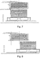
- Fig. 7 While the further stacking takes place on the stack changing device (11) as in the previous step due to the continuous feeding, the receiving table (2) with the stack located on the pallet (10) is lowered to the floor level. The pallet (10) with stack is exchanged for an empty pallet and the process begins again.
- Fig. 8 )
- the batch production according to the invention always begins with the use of the adapter range according to the invention.
- the dimensions of the adapter pallet represent a sheet stack with a pallet to enable the continuous stacking process to be started without any problems.
- the size and position of the adapter pallet on the receiving table is preferably independent of the format of the sheets. Different pallet formats, such as Europool pallets, system pallets, etc. can also be used in combination with the adapter pallet.
- the adapter range according to the invention is an effective, structurally simple and therefore inexpensive solution to the problem described at the beginning.
Landscapes
- Engineering & Computer Science (AREA)
- Mechanical Engineering (AREA)
- Pile Receivers (AREA)
- Stacking Of Articles And Auxiliary Devices (AREA)
Claims (10)
- Procédé de production de piles grandes de feuilles grand format (6), pour couvrir une distance verticale entre un plan d'amenée des feuilles (6) et un plan de sol, une plateforme de dépose étant réalisée sous la forme d'une table de réception de pile (2) mobile verticalement de haut en bas, sur la table de réception de pile (2), on place une palette (10) sur laquelle les feuilles (6) sont déposées pour former des piles, la table de réception de pile (2) étant déplacée au moyen d'un dispositif de levage dans une position finale supérieure et les feuilles (6) de la palette (10) étant acheminées en continu, pendant l'acheminement continu, la table de réception de pile (2), ensemble avec la palette (10), étant abaissée en continu pour assurer un empilement uniforme, ensuite lorsque la hauteur d'empilement souhaitée est atteinte, un dispositif de changement de pile (11) se déplace entre deux feuilles (6) et les sépare complètement l'une de l'autre, la pile suivante étant formée sur la face supérieure de la table de réception de pile (2) formée comme un fond d'introduction, le fond d'introduction étant abaissé en continu, tandis que la table de réception (2) se déplace dans sa position finale inférieure à la hauteur de la zone de sol et que le transport de la palette (10) avec la pile formée se poursuit, ensuite la table de réception de pile (2) avec une nouvelle palette vide (10) étant déplacée à la hauteur du dispositif de changement de pile (11) et le dispositif de changement de pile (11) revenant horizontalement dans sa position initiale et ainsi la pile se formant sur la palette vide (10) étant déchargé, après quoi la palette (10) ou la table de réception d'empilement (2) étant de nouveau abaissée en continu jusqu'à ce que la hauteur de pile souhaitée soit atteinte et que le dispositif de changement de pile (11) se déplace à nouveau entre deux feuilles (6) pour séparer la pile, caractérisé en ce qu'une palette d'adaptation (1) construite bien plus haute qu'une palette classique est utilisée uniquement au début de la formation continue de la pile.
- Procédé selon la revendication 1, caractérisé en ce que la palette d'adaptation (1) est mise en place manuellement, par exemple avec un transpalette à main, avant ou au plus tard au début de la formation de pile sur la table de réception de pile (2).
- Procédé selon la revendication 1 ou 2, caractérisé en ce que pour le positionnement correct de la palette d'adaptation (1) sur la table de réception (2), des dispositifs d'alignement (3) sont déplacés horizontalement dans une position définie et contre lesquels la palette d'adaptation (1) est en butée.
- Procédé selon la revendication 3, caractérisé en ce que la palette d'adaptation (1) avec les dispositifs d'alignement (3) est positionnée de sorte que le côté de la palette (1) faisant face au dispositif d'amenée (7) soit au niveau du convoyeur d'amenée (7).
- Procédé selon l'une des revendications précédentes, caractérisé en ce que l'utilisation de la palette d'adaptation (1) est détectée au moyen d'un ou plusieurs capteurs (4).
- Procédé selon la revendication 3 ou 4, caractérisé en ce que, lorsque la palette d'adaptation (1) est en position, les dispositifs d'alignement (3) sont rétractés et la table de réception de pile (2) se déplace dans sa position verticale la plus haute.
- Procédé selon l'une des revendications précédentes, caractérisé en ce que, lorsque la table de réception (2) est dans la position la plus haute, la surface de la palette d'adaptation (1) repose presque à la hauteur du plan du dispositif d'amenée, dans lequel, en cette position du convoyeur d'amenée (7), un ou plusieurs doigts de séparation (5) s'étendent latéralement sur la palette d'adaptation (1) et la production commence et les feuilles (6) sont empilées sur la palette d'adaptation (1).
- Procédé selon la revendication 7, caractérisé en ce que pour un empilement uniforme, la vitesse de transport de la table de réception (2) et du dispositif de butée (8) est abaissée en continu, le ou les doigts de séparation (5) étant déplacés verticalement vers le bas à la même vitesse.
- Procédé selon la revendication 7 ou 8, caractérisé en ce que, lorsque le ou les doigts de séparation (5) ont atteint leur position finale inférieure, le dispositif de changement de pile (11) est déplacé entre les feuilles soulevées par le doigt de séparation (5) d'un côté et la palette d'adaptation (1), de sorte que la pile de feuilles repose complètement sur le dispositif de changement de pile (11) et que le dispositif de changement de pile (11) soit également abaissé de manière uniforme par la suite, afin de continuer à empiler en continu dans le cas d'un transport de feuille en continu.
- Procédé selon l'une des revendications précédentes, caractérisé en ce que la palette d'adaptation vide (1) est abaissée jusqu'au niveau du sol et remplacée par une palette conventionnelle (10), puis la table de réception (2) se déplace avec la palette vide (10) à la hauteur du dispositif de changement de pile (11), le dispositif de changement de pile (11) étant ensuite déplacé horizontalement vers sa position de départ, déchargeant ainsi la pile se formant sur la palette vide (10).
Applications Claiming Priority (2)
| Application Number | Priority Date | Filing Date | Title |
|---|---|---|---|
| DE102013214338 | 2013-07-23 | ||
| PCT/EP2014/065721 WO2015011138A1 (fr) | 2013-07-23 | 2014-07-22 | Palette d'adaptation pour dispositif d'empilage |
Publications (2)
| Publication Number | Publication Date |
|---|---|
| EP3024767A1 EP3024767A1 (fr) | 2016-06-01 |
| EP3024767B1 true EP3024767B1 (fr) | 2020-01-08 |
Family
ID=51211789
Family Applications (1)
| Application Number | Title | Priority Date | Filing Date |
|---|---|---|---|
| EP14741636.6A Active EP3024767B1 (fr) | 2013-07-23 | 2014-07-22 | Procédé pour la production de piles grandes de feuilles grand format |
Country Status (3)
| Country | Link |
|---|---|
| EP (1) | EP3024767B1 (fr) |
| DE (1) | DE102014214237A1 (fr) |
| WO (1) | WO2015011138A1 (fr) |
Families Citing this family (3)
| Publication number | Priority date | Publication date | Assignee | Title |
|---|---|---|---|---|
| DE102016209339A1 (de) | 2015-11-23 | 2017-05-24 | Koenig & Bauer Ag | Vorrichtung zum Behandeln von Substraten |
| DE102017003503A1 (de) | 2016-04-11 | 2017-11-16 | Barry-Wehmiller Bielomatik Gmbh | Verfahren zur Herstellung von Stapeln aus Bögen |
| CN115841921A (zh) * | 2022-11-18 | 2023-03-24 | 杭州光之神科技发展有限公司 | 超高层数的贴片式叠层机 |
Family Cites Families (2)
| Publication number | Priority date | Publication date | Assignee | Title |
|---|---|---|---|---|
| DE3028865C2 (de) * | 1980-07-30 | 1983-12-01 | M.A.N.- Roland Druckmaschinen AG, 6050 Offenbach | Zwischenstapeleinrichtung für Non-Stop-Stapelwechsel in Auslegern von Druckmaschinen |
| ES2113240B1 (es) * | 1994-03-18 | 1999-01-01 | Alvarez Ochoa Jose Francisco | Adaptador para pallets. |
-
2014
- 2014-07-22 DE DE102014214237.7A patent/DE102014214237A1/de not_active Withdrawn
- 2014-07-22 EP EP14741636.6A patent/EP3024767B1/fr active Active
- 2014-07-22 WO PCT/EP2014/065721 patent/WO2015011138A1/fr not_active Ceased
Non-Patent Citations (1)
| Title |
|---|
| None * |
Also Published As
| Publication number | Publication date |
|---|---|
| DE102014214237A1 (de) | 2015-01-29 |
| EP3024767A1 (fr) | 2016-06-01 |
| WO2015011138A1 (fr) | 2015-01-29 |
Similar Documents
| Publication | Publication Date | Title |
|---|---|---|
| DE2534819C2 (de) | Vorrichtung zum Entstapeln und Transportieren von Platinen | |
| EP3533135B1 (fr) | Dispositif et procédé de liaison de parties de tôles à un paquet de tôles | |
| EP3241791B1 (fr) | Procédé de fabrication d'empilements de feuilles | |
| EP1724078B1 (fr) | Dispositif pour pousser une section de pile avec au moins une pièce en forme de plaque d'une pile restante | |
| WO2014094184A1 (fr) | Dispositif de dégerbage et procédé de dégerbage de tôles métalliques | |
| DE2332988A1 (de) | Verfahren und vorrichtung zum entladen und stapeln von gegenstaenden, insbesondere von ziegeln | |
| EP1456106B1 (fr) | Procede et dispositif pour former des groupes d'objets plats | |
| EP1484270A2 (fr) | Dispositif et procédé de traitement ultérieur d'une rame résiduelle avec ménagement et sans déchets | |
| EP2418163B1 (fr) | Dispositif de chargement pour piles de feuilles | |
| EP3024767A1 (fr) | Palette d'adaptation pour dispositif d'empilage | |
| EP2505536B1 (fr) | Dispositif de formation de piles | |
| DE3304673C2 (de) | Verfahren zum Wechseln eines Bogenstapels bei ununterbrochener Förderung von Bogen zur Stapelstelle | |
| DE3048117A1 (de) | Vorrichtung zum trennen eines endrohlings von einem stapel von rohlingen | |
| DE202017004863U1 (de) | Anlage zum Lagern und Transportieren von Paletten | |
| DE102015119321B4 (de) | Vorrichtung zum Umgang mit Stückgütern mit einer hiermit in Zusammenhang stehenden Erzeugung und Handhabung von Zwischenlagen | |
| EP3527500B1 (fr) | Dispositif d'emballage pour articles et procédés de fonctionnement d'un dispositif d'emballage permettant de manipuler des coupes d'emballage planes | |
| DE2528126C3 (de) | Einrichtung zur gruppenweisen Abgabe gestapelter Behälter | |
| EP2253565A2 (fr) | Dispositif d'empilage destiné à empiler de pièces en bois, en plastique ou analogues et son procédé | |
| EP1135319A2 (fr) | Dispositif de stockage de piles d'un dispositif d'impression | |
| EP2617667B1 (fr) | Procédé et dispositif de formation de paquets ou de paquets partiels à partir de produits imprimés empilés en vrac | |
| EP3208098B1 (fr) | Machine à appliquer les couvertures et procédé de fourniture de couvertures de livre | |
| DE3820236A1 (de) | Aufgabevorrichtung von aus plattenstapel gebildeten paketen und verfahren zum bereitstellen der pakete auf der aufgabevorrichtung | |
| EP1348653B1 (fr) | Dispositif de formation de paquets de produits d'imprimerie empilés et de formation de palettes composées de tels paquets | |
| DE2725831B2 (de) | Vorrichtung zum Entstapeln der obersten Folie eines Folienstapels | |
| DE3633601C2 (fr) |
Legal Events
| Date | Code | Title | Description |
|---|---|---|---|
| PUAI | Public reference made under article 153(3) epc to a published international application that has entered the european phase |
Free format text: ORIGINAL CODE: 0009012 |
|
| 17P | Request for examination filed |
Effective date: 20160122 |
|
| AK | Designated contracting states |
Kind code of ref document: A1 Designated state(s): AL AT BE BG CH CY CZ DE DK EE ES FI FR GB GR HR HU IE IS IT LI LT LU LV MC MK MT NL NO PL PT RO RS SE SI SK SM TR |
|
| AX | Request for extension of the european patent |
Extension state: BA ME |
|
| RAP1 | Party data changed (applicant data changed or rights of an application transferred) |
Owner name: BIELOMATIK LEUZE GMBH + CO. KG |
|
| DAX | Request for extension of the european patent (deleted) | ||
| RAP1 | Party data changed (applicant data changed or rights of an application transferred) |
Owner name: BW PAPERSYSTEMS STUTTGART GMBH |
|
| GRAP | Despatch of communication of intention to grant a patent |
Free format text: ORIGINAL CODE: EPIDOSNIGR1 |
|
| STAA | Information on the status of an ep patent application or granted ep patent |
Free format text: STATUS: GRANT OF PATENT IS INTENDED |
|
| INTG | Intention to grant announced |
Effective date: 20190911 |
|
| GRAS | Grant fee paid |
Free format text: ORIGINAL CODE: EPIDOSNIGR3 |
|
| GRAA | (expected) grant |
Free format text: ORIGINAL CODE: 0009210 |
|
| STAA | Information on the status of an ep patent application or granted ep patent |
Free format text: STATUS: THE PATENT HAS BEEN GRANTED |
|
| AK | Designated contracting states |
Kind code of ref document: B1 Designated state(s): AL AT BE BG CH CY CZ DE DK EE ES FI FR GB GR HR HU IE IS IT LI LT LU LV MC MK MT NL NO PL PT RO RS SE SI SK SM TR |
|
| REG | Reference to a national code |
Ref country code: GB Ref legal event code: FG4D Free format text: NOT ENGLISH |
|
| REG | Reference to a national code |
Ref country code: CH Ref legal event code: EP |
|
| REG | Reference to a national code |
Ref country code: DE Ref legal event code: R096 Ref document number: 502014013434 Country of ref document: DE |
|
| REG | Reference to a national code |
Ref country code: IE Ref legal event code: FG4D Free format text: LANGUAGE OF EP DOCUMENT: GERMAN |
|
| REG | Reference to a national code |
Ref country code: AT Ref legal event code: REF Ref document number: 1222443 Country of ref document: AT Kind code of ref document: T Effective date: 20200215 |
|
| REG | Reference to a national code |
Ref country code: NL Ref legal event code: MP Effective date: 20200108 |
|
| REG | Reference to a national code |
Ref country code: LT Ref legal event code: MG4D |
|
| PG25 | Lapsed in a contracting state [announced via postgrant information from national office to epo] |
Ref country code: PT Free format text: LAPSE BECAUSE OF FAILURE TO SUBMIT A TRANSLATION OF THE DESCRIPTION OR TO PAY THE FEE WITHIN THE PRESCRIBED TIME-LIMIT Effective date: 20200531 Ref country code: NL Free format text: LAPSE BECAUSE OF FAILURE TO SUBMIT A TRANSLATION OF THE DESCRIPTION OR TO PAY THE FEE WITHIN THE PRESCRIBED TIME-LIMIT Effective date: 20200108 Ref country code: FI Free format text: LAPSE BECAUSE OF FAILURE TO SUBMIT A TRANSLATION OF THE DESCRIPTION OR TO PAY THE FEE WITHIN THE PRESCRIBED TIME-LIMIT Effective date: 20200108 Ref country code: LT Free format text: LAPSE BECAUSE OF FAILURE TO SUBMIT A TRANSLATION OF THE DESCRIPTION OR TO PAY THE FEE WITHIN THE PRESCRIBED TIME-LIMIT Effective date: 20200108 Ref country code: RS Free format text: LAPSE BECAUSE OF FAILURE TO SUBMIT A TRANSLATION OF THE DESCRIPTION OR TO PAY THE FEE WITHIN THE PRESCRIBED TIME-LIMIT Effective date: 20200108 Ref country code: NO Free format text: LAPSE BECAUSE OF FAILURE TO SUBMIT A TRANSLATION OF THE DESCRIPTION OR TO PAY THE FEE WITHIN THE PRESCRIBED TIME-LIMIT Effective date: 20200408 |
|
| PG25 | Lapsed in a contracting state [announced via postgrant information from national office to epo] |
Ref country code: HR Free format text: LAPSE BECAUSE OF FAILURE TO SUBMIT A TRANSLATION OF THE DESCRIPTION OR TO PAY THE FEE WITHIN THE PRESCRIBED TIME-LIMIT Effective date: 20200108 Ref country code: BG Free format text: LAPSE BECAUSE OF FAILURE TO SUBMIT A TRANSLATION OF THE DESCRIPTION OR TO PAY THE FEE WITHIN THE PRESCRIBED TIME-LIMIT Effective date: 20200408 Ref country code: GR Free format text: LAPSE BECAUSE OF FAILURE TO SUBMIT A TRANSLATION OF THE DESCRIPTION OR TO PAY THE FEE WITHIN THE PRESCRIBED TIME-LIMIT Effective date: 20200409 Ref country code: LV Free format text: LAPSE BECAUSE OF FAILURE TO SUBMIT A TRANSLATION OF THE DESCRIPTION OR TO PAY THE FEE WITHIN THE PRESCRIBED TIME-LIMIT Effective date: 20200108 Ref country code: SE Free format text: LAPSE BECAUSE OF FAILURE TO SUBMIT A TRANSLATION OF THE DESCRIPTION OR TO PAY THE FEE WITHIN THE PRESCRIBED TIME-LIMIT Effective date: 20200108 Ref country code: IS Free format text: LAPSE BECAUSE OF FAILURE TO SUBMIT A TRANSLATION OF THE DESCRIPTION OR TO PAY THE FEE WITHIN THE PRESCRIBED TIME-LIMIT Effective date: 20200508 |
|
| REG | Reference to a national code |
Ref country code: DE Ref legal event code: R097 Ref document number: 502014013434 Country of ref document: DE |
|
| PG25 | Lapsed in a contracting state [announced via postgrant information from national office to epo] |
Ref country code: DK Free format text: LAPSE BECAUSE OF FAILURE TO SUBMIT A TRANSLATION OF THE DESCRIPTION OR TO PAY THE FEE WITHIN THE PRESCRIBED TIME-LIMIT Effective date: 20200108 Ref country code: SM Free format text: LAPSE BECAUSE OF FAILURE TO SUBMIT A TRANSLATION OF THE DESCRIPTION OR TO PAY THE FEE WITHIN THE PRESCRIBED TIME-LIMIT Effective date: 20200108 Ref country code: EE Free format text: LAPSE BECAUSE OF FAILURE TO SUBMIT A TRANSLATION OF THE DESCRIPTION OR TO PAY THE FEE WITHIN THE PRESCRIBED TIME-LIMIT Effective date: 20200108 Ref country code: RO Free format text: LAPSE BECAUSE OF FAILURE TO SUBMIT A TRANSLATION OF THE DESCRIPTION OR TO PAY THE FEE WITHIN THE PRESCRIBED TIME-LIMIT Effective date: 20200108 Ref country code: SK Free format text: LAPSE BECAUSE OF FAILURE TO SUBMIT A TRANSLATION OF THE DESCRIPTION OR TO PAY THE FEE WITHIN THE PRESCRIBED TIME-LIMIT Effective date: 20200108 Ref country code: CZ Free format text: LAPSE BECAUSE OF FAILURE TO SUBMIT A TRANSLATION OF THE DESCRIPTION OR TO PAY THE FEE WITHIN THE PRESCRIBED TIME-LIMIT Effective date: 20200108 Ref country code: ES Free format text: LAPSE BECAUSE OF FAILURE TO SUBMIT A TRANSLATION OF THE DESCRIPTION OR TO PAY THE FEE WITHIN THE PRESCRIBED TIME-LIMIT Effective date: 20200108 |
|
| PLBE | No opposition filed within time limit |
Free format text: ORIGINAL CODE: 0009261 |
|
| STAA | Information on the status of an ep patent application or granted ep patent |
Free format text: STATUS: NO OPPOSITION FILED WITHIN TIME LIMIT |
|
| 26N | No opposition filed |
Effective date: 20201009 |
|
| PG25 | Lapsed in a contracting state [announced via postgrant information from national office to epo] |
Ref country code: IT Free format text: LAPSE BECAUSE OF FAILURE TO SUBMIT A TRANSLATION OF THE DESCRIPTION OR TO PAY THE FEE WITHIN THE PRESCRIBED TIME-LIMIT Effective date: 20200108 |
|
| REG | Reference to a national code |
Ref country code: DE Ref legal event code: R119 Ref document number: 502014013434 Country of ref document: DE |
|
| PG25 | Lapsed in a contracting state [announced via postgrant information from national office to epo] |
Ref country code: SI Free format text: LAPSE BECAUSE OF FAILURE TO SUBMIT A TRANSLATION OF THE DESCRIPTION OR TO PAY THE FEE WITHIN THE PRESCRIBED TIME-LIMIT Effective date: 20200108 Ref country code: MC Free format text: LAPSE BECAUSE OF FAILURE TO SUBMIT A TRANSLATION OF THE DESCRIPTION OR TO PAY THE FEE WITHIN THE PRESCRIBED TIME-LIMIT Effective date: 20200108 Ref country code: PL Free format text: LAPSE BECAUSE OF FAILURE TO SUBMIT A TRANSLATION OF THE DESCRIPTION OR TO PAY THE FEE WITHIN THE PRESCRIBED TIME-LIMIT Effective date: 20200108 |
|
| REG | Reference to a national code |
Ref country code: CH Ref legal event code: PL |
|
| GBPC | Gb: european patent ceased through non-payment of renewal fee |
Effective date: 20200722 |
|
| REG | Reference to a national code |
Ref country code: BE Ref legal event code: MM Effective date: 20200731 |
|
| PG25 | Lapsed in a contracting state [announced via postgrant information from national office to epo] |
Ref country code: LI Free format text: LAPSE BECAUSE OF NON-PAYMENT OF DUE FEES Effective date: 20200731 Ref country code: GB Free format text: LAPSE BECAUSE OF NON-PAYMENT OF DUE FEES Effective date: 20200722 Ref country code: CH Free format text: LAPSE BECAUSE OF NON-PAYMENT OF DUE FEES Effective date: 20200731 Ref country code: FR Free format text: LAPSE BECAUSE OF NON-PAYMENT OF DUE FEES Effective date: 20200731 Ref country code: LU Free format text: LAPSE BECAUSE OF NON-PAYMENT OF DUE FEES Effective date: 20200722 |
|
| PG25 | Lapsed in a contracting state [announced via postgrant information from national office to epo] |
Ref country code: DE Free format text: LAPSE BECAUSE OF NON-PAYMENT OF DUE FEES Effective date: 20210202 Ref country code: BE Free format text: LAPSE BECAUSE OF NON-PAYMENT OF DUE FEES Effective date: 20200731 |
|
| PG25 | Lapsed in a contracting state [announced via postgrant information from national office to epo] |
Ref country code: IE Free format text: LAPSE BECAUSE OF NON-PAYMENT OF DUE FEES Effective date: 20200722 |
|
| REG | Reference to a national code |
Ref country code: AT Ref legal event code: MM01 Ref document number: 1222443 Country of ref document: AT Kind code of ref document: T Effective date: 20200722 |
|
| PG25 | Lapsed in a contracting state [announced via postgrant information from national office to epo] |
Ref country code: AT Free format text: LAPSE BECAUSE OF NON-PAYMENT OF DUE FEES Effective date: 20200722 |
|
| PG25 | Lapsed in a contracting state [announced via postgrant information from national office to epo] |
Ref country code: TR Free format text: LAPSE BECAUSE OF FAILURE TO SUBMIT A TRANSLATION OF THE DESCRIPTION OR TO PAY THE FEE WITHIN THE PRESCRIBED TIME-LIMIT Effective date: 20200108 Ref country code: MT Free format text: LAPSE BECAUSE OF FAILURE TO SUBMIT A TRANSLATION OF THE DESCRIPTION OR TO PAY THE FEE WITHIN THE PRESCRIBED TIME-LIMIT Effective date: 20200108 Ref country code: CY Free format text: LAPSE BECAUSE OF FAILURE TO SUBMIT A TRANSLATION OF THE DESCRIPTION OR TO PAY THE FEE WITHIN THE PRESCRIBED TIME-LIMIT Effective date: 20200108 |
|
| PG25 | Lapsed in a contracting state [announced via postgrant information from national office to epo] |
Ref country code: MK Free format text: LAPSE BECAUSE OF FAILURE TO SUBMIT A TRANSLATION OF THE DESCRIPTION OR TO PAY THE FEE WITHIN THE PRESCRIBED TIME-LIMIT Effective date: 20200108 Ref country code: AL Free format text: LAPSE BECAUSE OF FAILURE TO SUBMIT A TRANSLATION OF THE DESCRIPTION OR TO PAY THE FEE WITHIN THE PRESCRIBED TIME-LIMIT Effective date: 20200108 |