EP3025183B1 - Vierachsiger kardan-flugzeugsensor - Google Patents
Vierachsiger kardan-flugzeugsensor Download PDFInfo
- Publication number
- EP3025183B1 EP3025183B1 EP14727289.2A EP14727289A EP3025183B1 EP 3025183 B1 EP3025183 B1 EP 3025183B1 EP 14727289 A EP14727289 A EP 14727289A EP 3025183 B1 EP3025183 B1 EP 3025183B1
- Authority
- EP
- European Patent Office
- Prior art keywords
- mirror
- sensor system
- electromagnetic radiation
- coelostat
- axis
- Prior art date
- Legal status (The legal status is an assumption and is not a legal conclusion. Google has not performed a legal analysis and makes no representation as to the accuracy of the status listed.)
- Active
Links
Images


Classifications
-
- G—PHYSICS
- G01—MEASURING; TESTING
- G01J—MEASUREMENT OF INTENSITY, VELOCITY, SPECTRAL CONTENT, POLARISATION, PHASE OR PULSE CHARACTERISTICS OF INFRARED, VISIBLE OR ULTRAVIOLET LIGHT; COLORIMETRY; RADIATION PYROMETRY
- G01J1/00—Photometry, e.g. photographic exposure meter
- G01J1/02—Details
- G01J1/04—Optical or mechanical part supplementary adjustable parts
- G01J1/0407—Optical elements not provided otherwise, e.g. manifolds, windows, holograms, gratings
-
- G—PHYSICS
- G01—MEASURING; TESTING
- G01J—MEASUREMENT OF INTENSITY, VELOCITY, SPECTRAL CONTENT, POLARISATION, PHASE OR PULSE CHARACTERISTICS OF INFRARED, VISIBLE OR ULTRAVIOLET LIGHT; COLORIMETRY; RADIATION PYROMETRY
- G01J1/00—Photometry, e.g. photographic exposure meter
- G01J1/02—Details
- G01J1/04—Optical or mechanical part supplementary adjustable parts
- G01J1/0403—Mechanical elements; Supports for optical elements; Scanning arrangements
-
- G—PHYSICS
- G01—MEASURING; TESTING
- G01S—RADIO DIRECTION-FINDING; RADIO NAVIGATION; DETERMINING DISTANCE OR VELOCITY BY USE OF RADIO WAVES; LOCATING OR PRESENCE-DETECTING BY USE OF THE REFLECTION OR RERADIATION OF RADIO WAVES; ANALOGOUS ARRANGEMENTS USING OTHER WAVES
- G01S17/00—Systems using the reflection or reradiation of electromagnetic waves other than radio waves, e.g. lidar systems
- G01S17/02—Systems using the reflection of electromagnetic waves other than radio waves
- G01S17/06—Systems determining position data of a target
- G01S17/46—Indirect determination of position data
- G01S17/48—Active triangulation systems, i.e. using the transmission and reflection of electromagnetic waves other than radio waves
-
- G—PHYSICS
- G01—MEASURING; TESTING
- G01S—RADIO DIRECTION-FINDING; RADIO NAVIGATION; DETERMINING DISTANCE OR VELOCITY BY USE OF RADIO WAVES; LOCATING OR PRESENCE-DETECTING BY USE OF THE REFLECTION OR RERADIATION OF RADIO WAVES; ANALOGOUS ARRANGEMENTS USING OTHER WAVES
- G01S17/00—Systems using the reflection or reradiation of electromagnetic waves other than radio waves, e.g. lidar systems
- G01S17/86—Combinations of lidar systems with systems other than lidar, radar or sonar, e.g. with direction finders
-
- G—PHYSICS
- G01—MEASURING; TESTING
- G01S—RADIO DIRECTION-FINDING; RADIO NAVIGATION; DETERMINING DISTANCE OR VELOCITY BY USE OF RADIO WAVES; LOCATING OR PRESENCE-DETECTING BY USE OF THE REFLECTION OR RERADIATION OF RADIO WAVES; ANALOGOUS ARRANGEMENTS USING OTHER WAVES
- G01S7/00—Details of systems according to groups G01S13/00, G01S15/00, G01S17/00
- G01S7/48—Details of systems according to groups G01S13/00, G01S15/00, G01S17/00 of systems according to group G01S17/00
- G01S7/481—Constructional features, e.g. arrangements of optical elements
- G01S7/4817—Constructional features, e.g. arrangements of optical elements relating to scanning
-
- G—PHYSICS
- G02—OPTICS
- G02B—OPTICAL ELEMENTS, SYSTEMS OR APPARATUS
- G02B27/00—Optical systems or apparatus not provided for by any of the groups G02B1/00 - G02B26/00, G02B30/00
- G02B27/64—Imaging systems using optical elements for stabilisation of the lateral and angular position of the image
- G02B27/644—Imaging systems using optical elements for stabilisation of the lateral and angular position of the image compensating for large deviations, e.g. maintaining a fixed line of sight while a vehicle on which the system is mounted changes course
-
- G—PHYSICS
- G01—MEASURING; TESTING
- G01S—RADIO DIRECTION-FINDING; RADIO NAVIGATION; DETERMINING DISTANCE OR VELOCITY BY USE OF RADIO WAVES; LOCATING OR PRESENCE-DETECTING BY USE OF THE REFLECTION OR RERADIATION OF RADIO WAVES; ANALOGOUS ARRANGEMENTS USING OTHER WAVES
- G01S17/00—Systems using the reflection or reradiation of electromagnetic waves other than radio waves, e.g. lidar systems
- G01S17/02—Systems using the reflection of electromagnetic waves other than radio waves
- G01S17/06—Systems determining position data of a target
- G01S17/42—Simultaneous measurement of distance and other co-ordinates
Definitions
- the IRST field of regard is very wide in azimuth (horizontal), but generally forward looking, whereas the standoff reconnaissance field of regard is wide in pitch (horizontal), but generally side looking.
- the targeting field of regard is generally very wide in elevation, and can extend from many degrees above the local horizon (forward) to many degrees past (behind) the local nadir (vertical) by as much as 60 degrees.
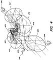
- the first coelostat mirror 220 corresponds to the coelostat mirror 120 discussed above as used in a similar system.
- the afocal foreoptics 110, fold mirror 210, and first and second coelostat mirrors 220, 230 are mounted on a roll gimbal that rotates about an outermost roll axis 242 (first gimbal axis) that is generally parallel to the beam of electromagnetic radiation output by the afocal foreoptics 110.
- the second coelostat mirror 230 directs the reflected radiation beam towards the fold mirror 210 which in turn directs the radiation towards either the afocal fore-optics 110 or towards the bypass mirror 325.
- the afocal fore-optics 110 comprises an afocal three-mirror anastigmat telescope.
- any number (e.g., two or more) anastigmat mirrors may be used as desired.
- a collimated radiation beam from the object or scene at far field received by the afocal fore-optics 110 is output by the afocal fore-optics as a collimated radiation beam of generally smaller diameter but correspondingly larger field of view.
- the WFOV insert mirror 320 and the bypass mirror 325 are moved away from the path of the radiation beam allowing only the radiation beam output by the afocal fore-optics 110 to reach the derotation device 330, whereas in the WFOV configuration, the bypass mirror 320 and WFOV mirror 325 are positioned in the path of the radiation beam so that the radiation beam bypasses afocal foreoptics 110 to reach the derotation device 330.
- a corner cube or prism 335 is used to reflect the auto-alignment beam back towards the back face of the laser dichroic mirror 315.
- the back face of the laser dichroic mirror 315 is configured to reflect a portion of the auto-alignment beam toward the imager 360.
- the imager 360 transmits the auto-alignment beam towards the beam splitter 372 which directs the auto-alignment beam towards the beam splitter 374.
- Beam splitter 372 is configured to reflect the auto-alignment beam and transmit the infrared radiation beam output by the imager 360.
- a third gimbal axis namely the second rotation axis 248 and the second coelostat mirror 230 may be used to compensate for platform pitch, allowing the first three gimbal axes (242, 244, and 246) to be used for tracking the object or scanning without significant disruption due to platform pitch.
- This compensation for platform pitch angle may be accomplished over a very large angular range, for example, in excess of +/- 45 degrees in elevation.
- the range of pitch angle compensation may only be limited by the field of regard of the window assembly 305, based on the design and geometry of that assembly, rather than by any limitations of the second coelostat mirror 230, or its range of travel.
Landscapes
- Physics & Mathematics (AREA)
- Engineering & Computer Science (AREA)
- General Physics & Mathematics (AREA)
- Radar, Positioning & Navigation (AREA)
- Remote Sensing (AREA)
- Computer Networks & Wireless Communication (AREA)
- Electromagnetism (AREA)
- Optics & Photonics (AREA)
- Spectroscopy & Molecular Physics (AREA)
- Optical Radar Systems And Details Thereof (AREA)
Claims (15)
- Sensorsystem, aufweisend:ein erstes optisches Subsystem (310b) mit einer ersten Vielzahl von optischen Elementen;ein zweites optisches Subsystem (310a), das zum Drehen um eine erste Kardanachse (242) bezüglich des ersten optischen Subsystems konfiguriert ist, wobei das zweite optische Subsystem enthält:eine afokale Voroptik (110), die zum Empfangen von elektromagnetischer Strahlung und Leiten eines kollimierten Strahls der elektromagnetischen Strahlung zum ersten optischen Subsystem konfiguriert ist;gekennzeichnet durcheinen ersten Coelostatenspiegel (220), der zum Drehen um eine zweite Kardanachse (244), welche im Wesentlichen senkrecht zur ersten Kardanachse (242) verläuft, und zum Empfangen und Reflektieren der elektromagnetischen Strahlung konfiguriert ist; undeinen zweiten Coelostatenspiegel (230), der zum Drehen um eine dritte Kardanachse (248), welche im Wesentlichen senkrecht zur ersten Kardanachse (242) sowie zur zweiten Kardanachse (244) verläuft, und zum Empfangen der elektromagnetischen Strahlung, die durch den ersten Coelostatenspiegel (220) reflektiert wird, und zum Leiten der elektromagnetischen Strahlung zur afokalen Voroptik (110) konfiguriert ist,wobei der erste Coelostatenspiegel (220) ferner zum Drehen um eine vierte Kardanachse (246) konfiguriert ist, welche im Wesentlichen senkrecht zur zweiten Kardanachse (244) und in einer Ebene des ersten Coelostatenspiegels (220) verläuft, wobei eine Drehung des ersten Coelostatenspiegels (220) um die vierte Kardanachse (246) eine Kardansingularität verhindert, bei der eine Sichtlinienrichtung im Wesentlichen mit der ersten Kardanachse (242) zusammenfällt.
- Sensorsystem nach Anspruch 1, wobei die erste Kardanachse im Wesentlichen parallel zum kollimierten Strahl von elektromagnetischer Strahlung, der durch die afokale Voroptik abgegeben wird, verläuft.
- Sensorsystem nach Anspruch 1, wobei die zweite Kardanachse einen Winkel von ungefähr 45 Grad bezüglich einer Ebene des ersten Coelostatenspiegels bildet und die zweite Kardanachse parallel zur elektromagnetischen Strahlung verläuft, die durch den ersten Coelostatenspiegel reflektiert wird.
- Sensorsystem nach Anspruch 1, wobei die dritte Kardanachse einen Winkel von ungefähr 45 Grad bezüglich einer Ebene des zweiten Coelostatenspiegels bildet und die dritte Kardanachse parallel zur elektromagnetischen Strahlung verläuft, die durch den zweiten Coelostatenspiegel reflektiert wird.
- Sensorsystem nach Anspruch 1, wobei das zweite optische Subsystem ferner einen Klappspiegel (210) enthält, der optisch zwischen die afokale Voroptik und den zweiten Coelostatenspiegel gekoppelt ist, wobei der Klappspiegel zum Empfangen der elektromagnetischen Strahlung vom zweiten Coelostatenspiegel und zum Reflektieren der elektromagnetischen Strahlung zur afokalen Voroptik hin konfiguriert ist.
- Sensorsystem nach Anspruch 1, wobei die afokale Voroptik einen Drei-Spiegel-Anastigmat enthält.
- Sensorsystem nach Anspruch 1, wobei die erste Vielzahl von optischen Elementen einen optischen Bildgeber (360) und einen Detektor (384) enthält, wobei der optische Bildgeber zum Empfangen der elektromagnetischen Strahlung vom zweiten optischen Subsystem und zum Weiterleiten der elektromagnetischen Strahlung an den Detektor konfiguriert ist.
- Sensorsystem nach Anspruch 7, wobei die erste Vielzahl von optischen Elementen ferner eine Derotationsvorrichtung (330) enthält, die zum Empfangen des kollimierten Strahls der elektromagnetischen Strahlung vom zweiten optischen Subsystem und zum Übertragen der elektromagnetischen Strahlung zum optischen Bildgeber hin konfiguriert ist, wobei die Derotationsvorrichtung zum gegenläufigen Drehen des kollimierten Strahls der elektromagnetischen Strahlung konfiguriert ist, sodass eine Bildausgabe durch die Derotationsvorrichtung in einer gleichen Richtung unabhängig von einer Drehung des ersten Coelostatenspiegels erfolgt.
- Sensorsystem nach Anspruch 1, wobei die erste Vielzahl von optischen Elementen ein Lasermodul (350) enthält, das zum Aussenden eines Laserstrahls und eines Selbstausrichtungsstrahls konfiguriert ist, wobei der Laserstrahl über die afokale Voroptik zum ersten Coelostatenspiegel hin gerichtet wird.
- Sensorsystem nach Anspruch 9, wobei der Selbstausrichtungsstrahl zum Bestimmen einer Sichtlinie des Laserstrahls benutzt wird.
- Sensorsystem nach Anspruch 1, wobei eine Drehung des ersten Coelostatenspiegels um die zweite Kardanachse eine Wanderung eines Bezugsfelds des Sensorsystems in einer Höhenrichtung vorsieht.
- Sensorsystem nach Anspruch 11, wobei das Bezugsfeld des Sensorsystems in der Höhenrichtung größer als ungefähr 165 Grad ist.
- Sensorsystem nach Anspruch 11, wobei eine Drehung des zweiten optischen Subsystems um die erste Kardanachse eine Wanderung des Bezugsfelds in einer Azimutrichtung vorsieht.
- Sensorsystem nach Anspruch 13, wobei das Bezugsfeld des Sensorsystems in der Azimutrichtung größer als ungefähr 140 Grad ist.
- Sensorsystem nach Anspruch 11, wobei eine Drehung des zweiten Coelostatenspiegels um die dritte Kardanachse eine Wanderung des Bezugsfelds in einer Steigungsrichtung vorsieht.
Applications Claiming Priority (2)
| Application Number | Priority Date | Filing Date | Title |
|---|---|---|---|
| US13/951,988 US9121758B2 (en) | 2013-07-26 | 2013-07-26 | Four-axis gimbaled airborne sensor having a second coelostat mirror to rotate about a third axis substantially perpendicular to both first and second axes |
| PCT/US2014/033228 WO2015012902A1 (en) | 2013-07-26 | 2014-04-07 | Four-axis gimbaled airborne sensor |
Publications (2)
| Publication Number | Publication Date |
|---|---|
| EP3025183A1 EP3025183A1 (de) | 2016-06-01 |
| EP3025183B1 true EP3025183B1 (de) | 2020-05-06 |
Family
ID=50842335
Family Applications (1)
| Application Number | Title | Priority Date | Filing Date |
|---|---|---|---|
| EP14727289.2A Active EP3025183B1 (de) | 2013-07-26 | 2014-04-07 | Vierachsiger kardan-flugzeugsensor |
Country Status (4)
| Country | Link |
|---|---|
| US (1) | US9121758B2 (de) |
| EP (1) | EP3025183B1 (de) |
| IL (1) | IL243724B (de) |
| WO (1) | WO2015012902A1 (de) |
Families Citing this family (12)
| Publication number | Priority date | Publication date | Assignee | Title |
|---|---|---|---|---|
| US9921396B2 (en) * | 2011-07-17 | 2018-03-20 | Ziva Corp. | Optical imaging and communications |
| US9762812B2 (en) | 2015-10-30 | 2017-09-12 | Raytheon Company | Dual-field-of-view optical system |
| DK201670595A1 (en) * | 2016-06-11 | 2018-01-22 | Apple Inc | Configuring context-specific user interfaces |
| US10189580B2 (en) | 2017-06-16 | 2019-01-29 | Aerobo | Image stabilization and pointing control mechanization for aircraft imaging systems |
| US20200145568A1 (en) * | 2018-02-13 | 2020-05-07 | Richard L. Vollmerhausen | Electro-optical imager field of regard coverage using vehicle motion |
| CN108445470B (zh) * | 2018-03-20 | 2023-02-17 | 山东理工大学 | 一种可实现直升机载激光雷达三维姿态角补偿的方法与装置 |
| US11754680B2 (en) | 2020-04-20 | 2023-09-12 | Raytheon Company | Optical system that detects and blocks backscatter |
| US11619709B2 (en) | 2020-04-20 | 2023-04-04 | Raytheon Company | Optical system to reduce local internal backscatter |
| US12228724B2 (en) * | 2020-07-10 | 2025-02-18 | Goodrich Corporation | Modular reconfigurable optical systems for supporting multiple modalities |
| US11268860B2 (en) | 2020-07-24 | 2022-03-08 | Raytheon Company | Radiometric calibration of detector |
| US12222495B2 (en) * | 2021-05-29 | 2025-02-11 | Teledyne Flir Defense, Inc. | Telescope and sensor systems and methods |
| FR3163737A1 (fr) * | 2024-06-19 | 2025-12-26 | Safran Electronics & Defense | Système d'observation comprenant un dispositif de télédétection par laser et un dispositif d'orientation d'un champ de faisceaux laser selon une pluralité de directions |
Family Cites Families (5)
| Publication number | Priority date | Publication date | Assignee | Title |
|---|---|---|---|---|
| FR2492516B1 (fr) | 1980-10-21 | 1985-09-20 | Thomson Csf | Dispositif a imagerie video, notamment pour autodirecteur |
| US7230724B2 (en) * | 2005-04-15 | 2007-06-12 | Specialty Minerals (Michigan) Inc. | Three-dimensional measuring apparatus for scanning an object and a measurement head of a three-dimensional measuring apparatus and method of using the same |
| US7307771B2 (en) | 2006-02-01 | 2007-12-11 | Textron Systems Corporation | Gimbal with orbiting mirror |
| US7648249B2 (en) | 2007-10-30 | 2010-01-19 | Raytheon Company | Beam-steering apparatus having five degrees of freedom of line-of-sight steering |
| US8759735B2 (en) | 2011-05-19 | 2014-06-24 | Raytheon Company | Multi-function airborne sensor system |
-
2013
- 2013-07-26 US US13/951,988 patent/US9121758B2/en active Active
-
2014
- 2014-04-07 WO PCT/US2014/033228 patent/WO2015012902A1/en not_active Ceased
- 2014-04-07 EP EP14727289.2A patent/EP3025183B1/de active Active
-
2016
- 2016-01-21 IL IL243724A patent/IL243724B/en active IP Right Grant
Non-Patent Citations (1)
| Title |
|---|
| None * |
Also Published As
| Publication number | Publication date |
|---|---|
| IL243724B (en) | 2020-04-30 |
| EP3025183A1 (de) | 2016-06-01 |
| IL243724A0 (en) | 2016-04-21 |
| US20150028194A1 (en) | 2015-01-29 |
| US9121758B2 (en) | 2015-09-01 |
| WO2015012902A1 (en) | 2015-01-29 |
Similar Documents
| Publication | Publication Date | Title |
|---|---|---|
| EP3025183B1 (de) | Vierachsiger kardan-flugzeugsensor | |
| EP2525235B1 (de) | Luftgestütztes multifunktionales Sensorsystem | |
| US9500518B2 (en) | Advanced optics for IRST sensor having afocal foreoptics positioned between a scanning coelostat mirror and focal imaging optics | |
| US9632166B2 (en) | Optical waveguide coude path for gimbaled systems having an optical coupling element | |
| US8536503B2 (en) | Faceted retro-mirror for line-of-sight jitter sensing | |
| EP3017266B1 (de) | Selbstausrichtungssystem für hochpräzisen stirnspiegel mit mast | |
| EP2564147B1 (de) | Optischer transceiver mit integriertem test | |
| US20080073484A1 (en) | Optical system | |
| US10659159B2 (en) | Combined imaging and laser communication system | |
| JPH0236926B2 (de) | ||
| WO2007078324A2 (en) | Laser-based system with ladar and sal capabilities | |
| US7657183B2 (en) | Method and apparatus for hemispherical retargeting | |
| US20190179130A1 (en) | Simultaneous multi-magnification reflective telescope utilizing a shared primary mirror | |
| US9841607B2 (en) | Method and apparatus for stabilizing a line of sight of a radiant energy system | |
| EP1579262A2 (de) | Optisches system | |
| EP3130955B1 (de) | Ausseraxiales optisches teleskop | |
| US12061334B2 (en) | Optical scanning system using micro-electro-mechanical system (mems) micro-mirror arrays (MMAs) | |
| Artamonov et al. | Analytical review of the development of laser location systems | |
| US20150049375A1 (en) | Compact beam director | |
| Fritze et al. | Innovative optronics for the new PUMA tank | |
| Armstrong et al. | Multimode IRST/FLIR design issues |
Legal Events
| Date | Code | Title | Description |
|---|---|---|---|
| PUAI | Public reference made under article 153(3) epc to a published international application that has entered the european phase |
Free format text: ORIGINAL CODE: 0009012 |
|
| 17P | Request for examination filed |
Effective date: 20160211 |
|
| AK | Designated contracting states |
Kind code of ref document: A1 Designated state(s): AL AT BE BG CH CY CZ DE DK EE ES FI FR GB GR HR HU IE IS IT LI LT LU LV MC MK MT NL NO PL PT RO RS SE SI SK SM TR |
|
| AX | Request for extension of the european patent |
Extension state: BA ME |
|
| DAX | Request for extension of the european patent (deleted) | ||
| REG | Reference to a national code |
Ref country code: DE Ref legal event code: R079 Ref document number: 602014064944 Country of ref document: DE Free format text: PREVIOUS MAIN CLASS: G02B0026100000 Ipc: G01J0001040000 |
|
| GRAP | Despatch of communication of intention to grant a patent |
Free format text: ORIGINAL CODE: EPIDOSNIGR1 |
|
| STAA | Information on the status of an ep patent application or granted ep patent |
Free format text: STATUS: GRANT OF PATENT IS INTENDED |
|
| RIC1 | Information provided on ipc code assigned before grant |
Ipc: G01S 17/02 20060101ALI20190424BHEP Ipc: G01S 17/42 20060101ALI20190424BHEP Ipc: G01S 7/481 20060101ALI20190424BHEP Ipc: G02B 26/10 20060101ALI20190424BHEP Ipc: G01J 1/04 20060101AFI20190424BHEP Ipc: G02B 27/64 20060101ALI20190424BHEP |
|
| INTG | Intention to grant announced |
Effective date: 20190523 |
|
| GRAJ | Information related to disapproval of communication of intention to grant by the applicant or resumption of examination proceedings by the epo deleted |
Free format text: ORIGINAL CODE: EPIDOSDIGR1 |
|
| STAA | Information on the status of an ep patent application or granted ep patent |
Free format text: STATUS: REQUEST FOR EXAMINATION WAS MADE |
|
| INTC | Intention to grant announced (deleted) | ||
| GRAP | Despatch of communication of intention to grant a patent |
Free format text: ORIGINAL CODE: EPIDOSNIGR1 |
|
| STAA | Information on the status of an ep patent application or granted ep patent |
Free format text: STATUS: GRANT OF PATENT IS INTENDED |
|
| INTG | Intention to grant announced |
Effective date: 20191126 |
|
| GRAS | Grant fee paid |
Free format text: ORIGINAL CODE: EPIDOSNIGR3 |
|
| GRAA | (expected) grant |
Free format text: ORIGINAL CODE: 0009210 |
|
| STAA | Information on the status of an ep patent application or granted ep patent |
Free format text: STATUS: THE PATENT HAS BEEN GRANTED |
|
| AK | Designated contracting states |
Kind code of ref document: B1 Designated state(s): AL AT BE BG CH CY CZ DE DK EE ES FI FR GB GR HR HU IE IS IT LI LT LU LV MC MK MT NL NO PL PT RO RS SE SI SK SM TR |
|
| REG | Reference to a national code |
Ref country code: GB Ref legal event code: FG4D |
|
| REG | Reference to a national code |
Ref country code: CH Ref legal event code: EP Ref country code: AT Ref legal event code: REF Ref document number: 1267526 Country of ref document: AT Kind code of ref document: T Effective date: 20200515 |
|
| REG | Reference to a national code |
Ref country code: IE Ref legal event code: FG4D |
|
| REG | Reference to a national code |
Ref country code: DE Ref legal event code: R096 Ref document number: 602014064944 Country of ref document: DE |
|
| REG | Reference to a national code |
Ref country code: LT Ref legal event code: MG4D |
|
| REG | Reference to a national code |
Ref country code: NL Ref legal event code: MP Effective date: 20200506 |
|
| PG25 | Lapsed in a contracting state [announced via postgrant information from national office to epo] |
Ref country code: GR Free format text: LAPSE BECAUSE OF FAILURE TO SUBMIT A TRANSLATION OF THE DESCRIPTION OR TO PAY THE FEE WITHIN THE PRESCRIBED TIME-LIMIT Effective date: 20200807 Ref country code: NO Free format text: LAPSE BECAUSE OF FAILURE TO SUBMIT A TRANSLATION OF THE DESCRIPTION OR TO PAY THE FEE WITHIN THE PRESCRIBED TIME-LIMIT Effective date: 20200806 Ref country code: IS Free format text: LAPSE BECAUSE OF FAILURE TO SUBMIT A TRANSLATION OF THE DESCRIPTION OR TO PAY THE FEE WITHIN THE PRESCRIBED TIME-LIMIT Effective date: 20200906 Ref country code: FI Free format text: LAPSE BECAUSE OF FAILURE TO SUBMIT A TRANSLATION OF THE DESCRIPTION OR TO PAY THE FEE WITHIN THE PRESCRIBED TIME-LIMIT Effective date: 20200506 Ref country code: PT Free format text: LAPSE BECAUSE OF FAILURE TO SUBMIT A TRANSLATION OF THE DESCRIPTION OR TO PAY THE FEE WITHIN THE PRESCRIBED TIME-LIMIT Effective date: 20200907 Ref country code: SE Free format text: LAPSE BECAUSE OF FAILURE TO SUBMIT A TRANSLATION OF THE DESCRIPTION OR TO PAY THE FEE WITHIN THE PRESCRIBED TIME-LIMIT Effective date: 20200506 Ref country code: LT Free format text: LAPSE BECAUSE OF FAILURE TO SUBMIT A TRANSLATION OF THE DESCRIPTION OR TO PAY THE FEE WITHIN THE PRESCRIBED TIME-LIMIT Effective date: 20200506 |
|
| PG25 | Lapsed in a contracting state [announced via postgrant information from national office to epo] |
Ref country code: BG Free format text: LAPSE BECAUSE OF FAILURE TO SUBMIT A TRANSLATION OF THE DESCRIPTION OR TO PAY THE FEE WITHIN THE PRESCRIBED TIME-LIMIT Effective date: 20200806 Ref country code: RS Free format text: LAPSE BECAUSE OF FAILURE TO SUBMIT A TRANSLATION OF THE DESCRIPTION OR TO PAY THE FEE WITHIN THE PRESCRIBED TIME-LIMIT Effective date: 20200506 Ref country code: LV Free format text: LAPSE BECAUSE OF FAILURE TO SUBMIT A TRANSLATION OF THE DESCRIPTION OR TO PAY THE FEE WITHIN THE PRESCRIBED TIME-LIMIT Effective date: 20200506 Ref country code: HR Free format text: LAPSE BECAUSE OF FAILURE TO SUBMIT A TRANSLATION OF THE DESCRIPTION OR TO PAY THE FEE WITHIN THE PRESCRIBED TIME-LIMIT Effective date: 20200506 |
|
| REG | Reference to a national code |
Ref country code: AT Ref legal event code: MK05 Ref document number: 1267526 Country of ref document: AT Kind code of ref document: T Effective date: 20200506 |
|
| PG25 | Lapsed in a contracting state [announced via postgrant information from national office to epo] |
Ref country code: NL Free format text: LAPSE BECAUSE OF FAILURE TO SUBMIT A TRANSLATION OF THE DESCRIPTION OR TO PAY THE FEE WITHIN THE PRESCRIBED TIME-LIMIT Effective date: 20200506 Ref country code: AL Free format text: LAPSE BECAUSE OF FAILURE TO SUBMIT A TRANSLATION OF THE DESCRIPTION OR TO PAY THE FEE WITHIN THE PRESCRIBED TIME-LIMIT Effective date: 20200506 |
|
| PG25 | Lapsed in a contracting state [announced via postgrant information from national office to epo] |
Ref country code: AT Free format text: LAPSE BECAUSE OF FAILURE TO SUBMIT A TRANSLATION OF THE DESCRIPTION OR TO PAY THE FEE WITHIN THE PRESCRIBED TIME-LIMIT Effective date: 20200506 Ref country code: ES Free format text: LAPSE BECAUSE OF FAILURE TO SUBMIT A TRANSLATION OF THE DESCRIPTION OR TO PAY THE FEE WITHIN THE PRESCRIBED TIME-LIMIT Effective date: 20200506 Ref country code: EE Free format text: LAPSE BECAUSE OF FAILURE TO SUBMIT A TRANSLATION OF THE DESCRIPTION OR TO PAY THE FEE WITHIN THE PRESCRIBED TIME-LIMIT Effective date: 20200506 Ref country code: SM Free format text: LAPSE BECAUSE OF FAILURE TO SUBMIT A TRANSLATION OF THE DESCRIPTION OR TO PAY THE FEE WITHIN THE PRESCRIBED TIME-LIMIT Effective date: 20200506 Ref country code: DK Free format text: LAPSE BECAUSE OF FAILURE TO SUBMIT A TRANSLATION OF THE DESCRIPTION OR TO PAY THE FEE WITHIN THE PRESCRIBED TIME-LIMIT Effective date: 20200506 Ref country code: IT Free format text: LAPSE BECAUSE OF FAILURE TO SUBMIT A TRANSLATION OF THE DESCRIPTION OR TO PAY THE FEE WITHIN THE PRESCRIBED TIME-LIMIT Effective date: 20200506 Ref country code: CZ Free format text: LAPSE BECAUSE OF FAILURE TO SUBMIT A TRANSLATION OF THE DESCRIPTION OR TO PAY THE FEE WITHIN THE PRESCRIBED TIME-LIMIT Effective date: 20200506 Ref country code: RO Free format text: LAPSE BECAUSE OF FAILURE TO SUBMIT A TRANSLATION OF THE DESCRIPTION OR TO PAY THE FEE WITHIN THE PRESCRIBED TIME-LIMIT Effective date: 20200506 |
|
| REG | Reference to a national code |
Ref country code: DE Ref legal event code: R097 Ref document number: 602014064944 Country of ref document: DE |
|
| PG25 | Lapsed in a contracting state [announced via postgrant information from national office to epo] |
Ref country code: PL Free format text: LAPSE BECAUSE OF FAILURE TO SUBMIT A TRANSLATION OF THE DESCRIPTION OR TO PAY THE FEE WITHIN THE PRESCRIBED TIME-LIMIT Effective date: 20200506 Ref country code: SK Free format text: LAPSE BECAUSE OF FAILURE TO SUBMIT A TRANSLATION OF THE DESCRIPTION OR TO PAY THE FEE WITHIN THE PRESCRIBED TIME-LIMIT Effective date: 20200506 |
|
| PLBE | No opposition filed within time limit |
Free format text: ORIGINAL CODE: 0009261 |
|
| STAA | Information on the status of an ep patent application or granted ep patent |
Free format text: STATUS: NO OPPOSITION FILED WITHIN TIME LIMIT |
|
| 26N | No opposition filed |
Effective date: 20210209 |
|
| PG25 | Lapsed in a contracting state [announced via postgrant information from national office to epo] |
Ref country code: SI Free format text: LAPSE BECAUSE OF FAILURE TO SUBMIT A TRANSLATION OF THE DESCRIPTION OR TO PAY THE FEE WITHIN THE PRESCRIBED TIME-LIMIT Effective date: 20200506 |
|
| PG25 | Lapsed in a contracting state [announced via postgrant information from national office to epo] |
Ref country code: MC Free format text: LAPSE BECAUSE OF FAILURE TO SUBMIT A TRANSLATION OF THE DESCRIPTION OR TO PAY THE FEE WITHIN THE PRESCRIBED TIME-LIMIT Effective date: 20200506 |
|
| PG25 | Lapsed in a contracting state [announced via postgrant information from national office to epo] |
Ref country code: LU Free format text: LAPSE BECAUSE OF NON-PAYMENT OF DUE FEES Effective date: 20210407 |
|
| REG | Reference to a national code |
Ref country code: BE Ref legal event code: MM Effective date: 20210430 |
|
| PG25 | Lapsed in a contracting state [announced via postgrant information from national office to epo] |
Ref country code: CH Free format text: LAPSE BECAUSE OF NON-PAYMENT OF DUE FEES Effective date: 20210430 Ref country code: LI Free format text: LAPSE BECAUSE OF NON-PAYMENT OF DUE FEES Effective date: 20210430 |
|
| PG25 | Lapsed in a contracting state [announced via postgrant information from national office to epo] |
Ref country code: IE Free format text: LAPSE BECAUSE OF NON-PAYMENT OF DUE FEES Effective date: 20210407 |
|
| PG25 | Lapsed in a contracting state [announced via postgrant information from national office to epo] |
Ref country code: BE Free format text: LAPSE BECAUSE OF NON-PAYMENT OF DUE FEES Effective date: 20210430 |
|
| PG25 | Lapsed in a contracting state [announced via postgrant information from national office to epo] |
Ref country code: HU Free format text: LAPSE BECAUSE OF FAILURE TO SUBMIT A TRANSLATION OF THE DESCRIPTION OR TO PAY THE FEE WITHIN THE PRESCRIBED TIME-LIMIT; INVALID AB INITIO Effective date: 20140407 |
|
| PG25 | Lapsed in a contracting state [announced via postgrant information from national office to epo] |
Ref country code: CY Free format text: LAPSE BECAUSE OF FAILURE TO SUBMIT A TRANSLATION OF THE DESCRIPTION OR TO PAY THE FEE WITHIN THE PRESCRIBED TIME-LIMIT Effective date: 20200506 |
|
| P01 | Opt-out of the competence of the unified patent court (upc) registered |
Effective date: 20230530 |
|
| PG25 | Lapsed in a contracting state [announced via postgrant information from national office to epo] |
Ref country code: MK Free format text: LAPSE BECAUSE OF FAILURE TO SUBMIT A TRANSLATION OF THE DESCRIPTION OR TO PAY THE FEE WITHIN THE PRESCRIBED TIME-LIMIT Effective date: 20200506 |
|
| PG25 | Lapsed in a contracting state [announced via postgrant information from national office to epo] |
Ref country code: MT Free format text: LAPSE BECAUSE OF FAILURE TO SUBMIT A TRANSLATION OF THE DESCRIPTION OR TO PAY THE FEE WITHIN THE PRESCRIBED TIME-LIMIT Effective date: 20200506 |
|
| PGFP | Annual fee paid to national office [announced via postgrant information from national office to epo] |
Ref country code: DE Payment date: 20250319 Year of fee payment: 12 |
|
| PG25 | Lapsed in a contracting state [announced via postgrant information from national office to epo] |
Ref country code: TR Free format text: LAPSE BECAUSE OF FAILURE TO SUBMIT A TRANSLATION OF THE DESCRIPTION OR TO PAY THE FEE WITHIN THE PRESCRIBED TIME-LIMIT Effective date: 20200506 |
|
| PGFP | Annual fee paid to national office [announced via postgrant information from national office to epo] |
Ref country code: GB Payment date: 20260319 Year of fee payment: 13 |
|
| PGFP | Annual fee paid to national office [announced via postgrant information from national office to epo] |
Ref country code: FR Payment date: 20260320 Year of fee payment: 13 |