EP3025316B1 - Système de sécurité à fonction d'appel de secours intégrée - Google Patents
Système de sécurité à fonction d'appel de secours intégrée Download PDFInfo
- Publication number
- EP3025316B1 EP3025316B1 EP13840174.0A EP13840174A EP3025316B1 EP 3025316 B1 EP3025316 B1 EP 3025316B1 EP 13840174 A EP13840174 A EP 13840174A EP 3025316 B1 EP3025316 B1 EP 3025316B1
- Authority
- EP
- European Patent Office
- Prior art keywords
- security system
- sensor
- distance
- alarm
- timer
- Prior art date
- Legal status (The legal status is an assumption and is not a legal conclusion. Google has not performed a legal analysis and makes no representation as to the accuracy of the status listed.)
- Active
Links
Images

Classifications
-
- G—PHYSICS
- G08—SIGNALLING
- G08B—SIGNALLING SYSTEMS, e.g. PERSONAL CALLING SYSTEMS; ORDER TELEGRAPHS; ALARM SYSTEMS
- G08B13/00—Burglar, theft or intruder alarms
- G08B13/18—Actuation by interference with heat, light, or radiation of shorter wavelength; Actuation by intruding sources of heat, light, or radiation of shorter wavelength
- G08B13/189—Actuation by interference with heat, light, or radiation of shorter wavelength; Actuation by intruding sources of heat, light, or radiation of shorter wavelength using passive radiation detection systems
- G08B13/19—Actuation by interference with heat, light, or radiation of shorter wavelength; Actuation by intruding sources of heat, light, or radiation of shorter wavelength using passive radiation detection systems using infrared-radiation detection systems
-
- G—PHYSICS
- G08—SIGNALLING
- G08B—SIGNALLING SYSTEMS, e.g. PERSONAL CALLING SYSTEMS; ORDER TELEGRAPHS; ALARM SYSTEMS
- G08B21/00—Alarms responsive to a single specified undesired or abnormal condition and not otherwise provided for
- G08B21/02—Alarms for ensuring the safety of persons
- G08B21/04—Alarms for ensuring the safety of persons responsive to non-activity, e.g. of elderly persons
- G08B21/0407—Alarms for ensuring the safety of persons responsive to non-activity, e.g. of elderly persons based on behaviour analysis
- G08B21/0415—Alarms for ensuring the safety of persons responsive to non-activity, e.g. of elderly persons based on behaviour analysis detecting absence of activity per se
-
- G—PHYSICS
- G08—SIGNALLING
- G08B—SIGNALLING SYSTEMS, e.g. PERSONAL CALLING SYSTEMS; ORDER TELEGRAPHS; ALARM SYSTEMS
- G08B21/00—Alarms responsive to a single specified undesired or abnormal condition and not otherwise provided for
- G08B21/02—Alarms for ensuring the safety of persons
- G08B21/04—Alarms for ensuring the safety of persons responsive to non-activity, e.g. of elderly persons
- G08B21/0438—Sensor means for detecting
- G08B21/0469—Presence detectors to detect unsafe condition, e.g. infrared sensor, microphone
-
- G—PHYSICS
- G08—SIGNALLING
- G08B—SIGNALLING SYSTEMS, e.g. PERSONAL CALLING SYSTEMS; ORDER TELEGRAPHS; ALARM SYSTEMS
- G08B21/00—Alarms responsive to a single specified undesired or abnormal condition and not otherwise provided for
- G08B21/02—Alarms for ensuring the safety of persons
- G08B21/04—Alarms for ensuring the safety of persons responsive to non-activity, e.g. of elderly persons
- G08B21/0438—Sensor means for detecting
- G08B21/0476—Cameras to detect unsafe condition, e.g. video cameras
-
- G—PHYSICS
- G08—SIGNALLING
- G08B—SIGNALLING SYSTEMS, e.g. PERSONAL CALLING SYSTEMS; ORDER TELEGRAPHS; ALARM SYSTEMS
- G08B25/00—Alarm systems in which the location of the alarm condition is signalled to a central station, e.g. fire or police telegraphic systems
- G08B25/001—Alarm cancelling procedures or alarm forwarding decisions, e.g. based on absence of alarm confirmation
-
- G—PHYSICS
- G08—SIGNALLING
- G08B—SIGNALLING SYSTEMS, e.g. PERSONAL CALLING SYSTEMS; ORDER TELEGRAPHS; ALARM SYSTEMS
- G08B25/00—Alarm systems in which the location of the alarm condition is signalled to a central station, e.g. fire or police telegraphic systems
- G08B25/01—Alarm systems in which the location of the alarm condition is signalled to a central station, e.g. fire or police telegraphic systems characterised by the transmission medium
- G08B25/08—Alarm systems in which the location of the alarm condition is signalled to a central station, e.g. fire or police telegraphic systems characterised by the transmission medium using communication transmission lines
-
- G—PHYSICS
- G08—SIGNALLING
- G08B—SIGNALLING SYSTEMS, e.g. PERSONAL CALLING SYSTEMS; ORDER TELEGRAPHS; ALARM SYSTEMS
- G08B25/00—Alarm systems in which the location of the alarm condition is signalled to a central station, e.g. fire or police telegraphic systems
- G08B25/01—Alarm systems in which the location of the alarm condition is signalled to a central station, e.g. fire or police telegraphic systems characterised by the transmission medium
- G08B25/10—Alarm systems in which the location of the alarm condition is signalled to a central station, e.g. fire or police telegraphic systems characterised by the transmission medium using wireless transmission systems
Definitions
- the present invention relates to a security system with an integrated emergency call function for an apartment, a single-family or multi-family house, or also for social institutions such as homes or hospitals.
- Such security systems with an emergency call function are usually based on an infrared motion detector and a timer and are used, for example, to enable older people to live independently for as long as possible, but still provide them with help in the event of an emergency.
- the motion detector signal triggers the expiration of a preset time interval in the timer, and if no further motion detector signal is received during this time interval, i.e. if the resident is inactive for too long, then the expiration of the time interval preset in the timer triggers the sending of an emergency call.
- the object of the present invention is to provide a security system with an integrated emergency call function, while avoiding the disadvantages outlined above, in which the detection of movement and the power supply are optimized.
- the security system should include numerous other functions in addition to the emergency call function.
- the solution to the problem consists first of all in selecting a motion detection system that is preferably microprocessor-supported and carries out a distance measurement using at least one distance sensor.
- this system is able to detect a change in a predetermined distance target value to a new distance actual value or the change in a first actual distance value to a new second actual distance value and thereby send a device-internal (delta of) distance measurement signal(s).
- a security system which essentially only comprises the distance sensor and a timer
- JP2002-340540 discloses a surveillance system with a large number of distance sensors that are able to detect the movement of a person passing through within a Cartesian coordinate system and by means of high-speed processing. This system is very complex in terms of equipment and computing power.
- the object of the present invention is to provide a security system with an integrated emergency call function while avoiding the disadvantages outlined above, in which the detection of movement to avoid false alarms when detecting inactivity of people and the power supply are optimized.
- the security system should include numerous other functions in addition to the emergency call function. Distance measurement signal from the distance sensor is used to switch on the timer.
- the distance measurement signal can preferably also be forwarded to a microprocessor or microcontroller integrated in the device, in which a threshold value can also be entered according to the invention and according to a preferred embodiment.
- This threshold value is preferably set in such a way that the trigger signal is only output to the timer by the microprocessor when the absolute value of the distance measurement signal exceeds it.
- the threshold value can be determined empirically, for example, and can preferably be adapted or corrected to any specific local conditions.
- the invention allows the microprocessor to distinguish in real time between minor, negligible distance measurement signals (movement of objects, pets, etc.) and those that should be triggered reliably because, for example, a person has been detected by the distance sensor(s).
- a security system can comprise one or more distance sensors for distance measurement, whereby all common types of distance sensors can be considered.
- Light or laser-based signals can be emitted, but also infrared or terahertz radiation, radio, microwaves or ultrasound.
- Capacitive or inductive distance measurements can also be considered in principle, although it may be more difficult to provide the necessary voltage or energy supply for this.
- Another possibility for distance measurement can be carried out using one or more electronic cameras or one or more CCDs, which can measure the parallax shift or the different stereo images are captured.
- the microprocessor preferably sends a trigger signal to switch on the timer when the absolute value of the distance measurement signal exceeds the predefined threshold value in the microprocessor.
- a specific time interval can be set in this timer, which begins to run after the distance measurement signal is received. If the set time interval runs out completely, i.e. the suspected inactivity in the room in question is suspiciously long, the microprocessor sends an alarm signal on the sensor side. If a new distance measurement signal is received while the set time interval has begun, this sequence is interrupted and a new one begins.
- the adjustable time interval does not have to be fixed; an algorithm-based dynamic adjustment of the same is preferred, for example to day and night, so that, for example, longer time intervals automatically run at night.
- At least one motion detector is connected upstream of the at least one distance sensor.
- At least the distance sensor(s) and the motion detector(s) are preferably housed in a common housing of a device, which is referred to below as the sensor device. All other modules, the microcontroller, the emergency telephone, the power supply and other parts can in principle also be arranged in the housing of the sensor device, or in one or each separate, external housing. The latter arrangement is particularly suitable if the security system is to be designed for an entire building with a large number of rooms or apartments and the data from all sensor devices are collected centrally.
- the motion detector can basically be a simple light barrier or a passive infrared sensor, for example.
- ultrasound-based motion detectors can also be considered, or those that work with electromagnetic waves (radars, Doppler radars or so-called bio-radars, which are designed to detect even the smallest movements of a person, for example the breathing movements or the heart and/or pulse rate of a buried person).
- the motion detector uses the detection of any movement in the room in which it is located, but preferably only to output a trigger signal to the microprocessor or the distance sensor.
- a qualitative detection of the type of movement by the motion detector is not carried out and only takes place through the distance measurement. This structure is preferred, but it would also be possible to evaluate both signals (distance and movement).
- a security system In order to achieve a reliable sensitivity, but also a certain selectivity, using the motion detector, it is preferable to equip a security system according to the invention with a motion detector which, in terms of its geometric definition and any optical elements, is preferably arranged at an approximate switch height in a range of 0.5 to 1.5 m, preferably approx. 1.1 m, and further preferably has an opening angle in a range of 5 to 90 degrees, preferably approx. 30 degrees, for both a horizontal and a vertical detection range.
- the nominal range for the motion detector is preferably in a range of 0.5 to 10 m and is preferably 2.0 m.
- the nominal range of the distance sensor can be smaller and is preferably in a range of 0.5 to 8 m and is preferably 1.3 m.
- the preferred speed detection at which the motion detector responds in terms of its performance is in a range of 0.1 to 3 m/s and is preferably 0.5 m/s. In this way, a person is reliably detected, but a pet running or jumping past quickly or even a fly flying past will not be detected.
- the power supply of the distance sensor - and preferably also of the microprocessor - is linked to the trigger signal of the motion detector, i.e. the distance sensor - and preferably also the microprocessor - is not constantly supplied with power, but only when it is activated by the trigger signal of the motion detector. In this context, it is logical to select a motion detector that uses as little power as possible and to use it only to generate a detection signal that switches on or "arms" the security system.
- an energy saving mode for the motion detector from which it then switches to a normal voltage mode when movement is detected or the interval time is exceeded.
- different time intervals can be set manually by means of the microprocessor and/or a rotary, rotary-sliding switch or DIP switch, in addition to a further preferably arranged Ethernet or KNX interface.
- fixed preset time intervals can be selected depending on the room in which the distance measurement is to be carried out, for example a time interval for the bedroom, a time interval for the living room or a time interval for the bathroom.
- the setting option for the time interval is mechanically and/or electronically secured against accidental adjustment.
- the setting of the time interval or the operation of all other functions of a security system according to the invention can also be carried out using a remote control, for example infrared or radio remote controls with corresponding receivers on a device that includes at least the microcontroller.
- a remote control for example infrared or radio remote controls with corresponding receivers on a device that includes at least the microcontroller.
- Smartphones, laptops, PCs and tablets can also take on the function of a remote control, provided that an Ethernet interface or a modem or a radio transmitter is provided.
- a security system preferably comprises a communication module for system-external communication.
- This can be a bidirectional GSM, KNX or ZIGBee, or serial, or parallel, or TCPIP or Ethernet or token ring-based interface, with the common communication protocols 6Lowpan, TCPIP, MQTT, etc. or can comprise several or all types of communication.
- the setting of the time interval, but also the triggering and monitoring of all functions of the security system can also be carried out externally in this way.
- a timeout circuit is provided so that if the configuration operation lasts too long or if confirmation inputs are missing, the system automatically reverts to the original configuration and normal operation, which corresponds to the original configuration corresponds.
- appropriate switches and appropriate software are preferably provided for switching the security system to an absence or holiday mode.
- the distance sensor(s) or the motion detector(s) or all sensors are deactivated and preferably also the timer(s).
- displays can be provided which preferably indicate cyclically both acoustically and visually that the security system is in absence or holiday mode. This informs the person who has returned that they must switch the security system back on.
- the motion detector(s) can be provided to supply at least the motion detector(s) with a standby mode voltage and thus automatically "start" the security system from the absence or holiday mode back to normal operation when movement is detected.
- the acoustic and optical displays emit an acknowledgeable warning signal for a certain period of time. In this way, it is ensured that a cleaner or a neighbor watering the flowers is informed to switch the security system back to the absence or holiday mode after completing their work.
- Switching to the absence or holiday mode is preferably carried out with a timer-supported time delay so that the movement of the departing person is not already considered a signal to switch back to the Normal mode is interpreted.
- warning signal described above can preferably be acknowledged using a confirmation switch, but also all other alarm signals from the security system, both the sensor-side alarm signal and the telephone-side alarm signal, i.e. the actual sending of the emergency call.
- This function is intended for switching off any false alarms, but also for switching off the alarm after the rescue personnel have arrived.
- switches and corresponding software are provided to trigger a test alarm, both for the external telephone-side or network-side alarm, and for the internal sensor-side alarm.
- the latter test function can preferably be combined with a time-lapse circuit of the timer, so that it is not necessary to wait for the entire set inactivity time interval to elapse.
- a security system automatically and cyclically carries out a self-test of the motion detector, the distance sensor, the timer, the software and the emergency telephone in normal operation, also with timer support.
- the self-test function is preferably set up in such a way that the data of a faulty self-test or at least the fact that a self-test was faulty can be stored as an error log in an error memory.
- This error memory can also preferably be read out by means of an external diagnostic device that can be connected to a diagnostic connection, which in turn is preferably arranged on the housing in which the microcontroller is housed.
- the state of the error memory is preferably stored on the housing of the security system or the Microcontroller is displayed optically or acoustically.
- the stored error also serves to make an emergency call in the event of a subsequent, repeated faulty self-test, preferably with an identifier that this is a technical emergency and not a personal emergency. If the subsequent self-test or, for reasons of redundancy, several of the following self-tests are error-free, then it can optionally be provided that the stored error is automatically deleted.
- the internal circuits and the software are preferably configured or separated in such a way that the automatic self-tests cannot cause any interruption of normal operation. Only a visual or acoustic display is provided to indicate that the self-test is currently being carried out. Furthermore, a self-test is automatically started after each restart, for example when commissioning and after a battery or accumulator change or power failure.
- a security system comprises at least one GSM and one Ethernet/WLAN communication module
- the telephone unit is preferably able to detect unsuccessful calls, e.g. on an answering machine, for example by being able to read a confirmation signal.
- a timer circuit can be arranged in the case of a simplex connection, which initiates a redundant repetition of the sensor-side alarm to the emergency telephone until an acknowledgement is made on the emergency telephone.
- a security system can be connected to the power grid, but preferably has a power supply by means of one or more rechargeable batteries or by means of one or more batteries.
- a circuit is arranged in the security system, for example with a voltage regulator or detector, which monitors the rechargeable battery or battery voltage.
- a minimum voltage can be entered as a switching threshold, and when the entered minimum voltage value is approached or undershot, the timer or timers are switched to set off an alarm.
- the alarm is preferably preceded by an optical and later acoustic warning signal, which occurs approx. 2-3 days beforehand.
- a switch is preferably arranged, by means of which the customer has the option of "slowing down" the warning signal once by approx. 12 hours, for example in the event that the voltage falls below the limit at night.
- the voltage check function can also be linked to the timer. In this way, voltage fluctuations that only briefly fall below the switching threshold will not trigger an alarm, but only those that exceed an adjustable period.
- both the sensor-side alarm which is essentially internal to the device or system
- the telephone-side emergency alarm also have a pre-alarm pre-stage that gives the customer or service personnel the opportunity to acknowledge or intervene.
- optical and acoustic signaling devices are preferably arranged on the device for the respective alarm and a corresponding direct button that stops the respective alarm immediately.
- This direct button can be secured with a mechanical lock.
- a circuit to the timer is preferably arranged that starts the expiration of a time interval within which the pre-alarm can be acknowledged. If this time interval expires without acknowledgement, the full sensor-side or telephone-side alarm is activated.
- a security system preferably comprises at least one non-volatile memory for storing the function or system-relevant data such as the set time interval, configuration data of the distance sensor and the motion detector, the communication interfaces, the emergency telephone, the alarm sequences, etc.
- the housing parts of a security system according to the invention are preferably made of plastic or metal and designed in such a way that they meet protection class IP 20, but preferably at least protection class IP 24 (splash-proof in damp rooms).
- the housing can have a top-bottom marking so that the installer has an installation guide and does not place a battery compartment above the electronics.
- the battery compartment preferably forms a tray that prevents battery fluid from leaking out.
- the housing preferably has a surface or pair of edges on which which can be used to precisely align the sensors during installation with a spirit level.
- the housing is preferably designed to be rounded so that everyday items such as keys, wallets, hats, gloves or scarves cannot be placed on it or can only be placed with great difficulty.
- the housing parts, but also the interfaces and not least the software, i.e. the entire architecture of a security system according to the invention, is preferably modular in design, so that a basic variant can be configured or expanded according to customer requirements and/or individual components can be exchanged.
- the software of a security system according to the invention preferably has a timer-controlled update function.
- the system-internal, but especially the system-external bidirectional communication modules can preferably be expanded to include interfaces for any other functions of a security system according to the invention.
- This involves the input and processing of different sensor signals such as a sensor signal from the door lock of the entrance door (open/closed/locked), building technology sensor signals (light/heating/windows/blinds/electrical switchboard and fuse panel), sensor signals from the kitchen stove (on/off/no vessel on the switched-on stove), sensor signal from an overflow protection device in the bathtub, sensor signals relating to the state of health (heart rate/pulse/blood pressure, etc.) and a sensor signal from a camera or scanner which optically records, for example, the occupancy image of the compartments of a tablet box with the prepared medication and compares it with a stored image.
- sensor signals such as a sensor signal from the door lock of the entrance door (open/closed/locked), building technology sensor signals (light/heating/windows/blinds/electrical switchboard and fuse
- the security system has a distance sensor and an upstream motion detector and is equipped with all the additional features and functions described so far, whereby an emergency call telephone unit is no longer provided, but rather a GSM module that sends an emergency call SMS.
- the security system according to the invention is a system in that the sensor device is self-sufficient as an independent device and only requires an external receiving or input unit, such as a smartphone.
- the emergency SMS can be sent to a central office, but also just to one person, e.g. to a specific caregiver or to a trusted person or relative.
- the security system according to the invention with a GSM module provides a communication module which comprises at least one Ethernet/WLAN module.
- Ethernet/WLAN module preferably with an assigned IP address
- remote maintenance of the security system is easily implemented and the possibility of updates is also easily solved.
- the sensor device Without the sensor device itself If a device needs a clock with a calendar function, the date and time information can be sent to the sensor device using the Ethernet/WLAN module.
- KNX, Token Ring and ZigBee also have the option of transmitting the date and time.
- an Ethernet/WLAN module enables a simple and, above all, wireless configuration of a network of several sensor devices, for example within an apartment, but also for certain areas of a home or hospital.
- Ethernet/WLAN module would make it possible to assign different functions to one or more sensor devices in a network.
- a sensor device could be assigned to record a person's activity rather than inactivity.
- an alarm can also be triggered by voice recognition. This is done using a microphone and a voice recognition software that is preferably capable of learning and can also be personalized, preferably additionally secured by keywords.
- a further embodiment of a security system according to the invention with a GSM and WLAN module is designed as a gateway for other alarm components by means of a built-in receiver.
- This can be any conceivable device capable of emitting an alarm, such as a wristband transmitter, a medallion, an emergency call cushion, etc., and other devices that send their alarm to the security system according to the invention, for example via a cable or radio.
- the sensor device has an internal telephone function with a hands-free connection, so that an emergency call by telephone or an emergency SMS can be checked against it, provided the person has not had an accident and can confirm it by voice, or has had an accident but can still speak and this is confirmed, or has had an accident, must be at home but can no longer speak.
- independent battery supplies are generally preferred in order to avoid power cables. If an Ethernet connection is provided, a PoE (Power over Ethernet) power supply can also be considered.
- a so-called low-power WLAN is preferred, which, for example, only needs to be switched on periodically and reduced and only increases to full transmission power when requested.
- induction loops can also be considered, which are arranged, for example, on the opposite side of the wall of a wet room or an entrance area.
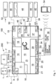
- the security system 100 comprises an infrared motion detector 1 and a distance sensor 2, which together form a sensor system 200.
- the infrared motion detector 1 is connected by a connecting line 3 to an analog-digital connection 8 with a motion detector interface 11, which further comprises a digital output 9 and a digital input 10.
- a test line 4 for testing the infrared motion detector 1 is connected to the digital output 9.
- An interrupt signal line 5 is arranged at the digital input 10.
- the distance sensor 2 is connected to a distance sensor interface 14 by means of a connecting line 6 to an analog-digital connection 12 and a switch-on line 7 from a digital output 13.
- the motion detector interface 11 and the distance sensor interface 14 are arranged on a microcontroller 15. The described connections and components ensure that the distance sensor 2 can only be switched on after a signal from the infrared motion detector 1 and, when this is the case, the infrared motion detector 1 can be switched off again.
- the security system 100 further comprises a timer 16 and a test interface 18 with a UART interface 17.
- the illustrated design variant of a The security system 100 according to the invention further comprises a simple communication interface 19 controlled by the microcontroller 15.
- a distance measurement signal DmS reaches the microcontroller 15 from the distance sensor 2 via the connecting line 6 or the analog-digital connection 12 of the distance sensor interface 14, the timer 16 is triggered or reset.
- the illustrated embodiment of a security system 100 further comprises a complex communication interface 29, which can switch on a communication module 36 via a digital output 30 and a switch-on line 31.
- the illustrated communication module 36 handles GSM, KNX and Ethernet communication, but individual, separate communication modules for each type of transmission are also possible.
- the communication module 36 and the complex communication interface 29 are also connected via a test line 33 to an analog-digital connection 32 and a permanent connection line 35 to a UART interface 34.
- the security system 100 further comprises an alarm output interface 37, which outputs an alarm signal AS to an alarm unit 40 via a digital output 38 and a connecting line 39.
- the alarm unit 40 can comprise both acoustic and optical alarm devices.
- An indication signal interface 41 outputs indication signals HS, such as the indication that a detection has taken place or that the security system 100 is in absence or holiday mode or that a self-test is currently taking place or that a self-test has failed or that the security system is currently in a configuration mode.
- indication signals HS are passed via at least one digital output 42 of the indication signal interface 41 and a connecting line 43 to a signaling device 44 such as a display or an arrangement of lights.
- the illustrated embodiment of a security system 100 further comprises a user input interface 45 with at least one digital input 46 and a connecting line 47, into which control or switching signals SS can be entered by a user or technical service personnel via a control and switching unit 48.
- a voltage monitor 49 is connected to an analog-digital connection 51 via a connecting line 50.
- a power supply 52 supplies all components of the security system 100 that are marked with an asterisk.
- the corresponding power lines are thus only symbolically represented by a power output 53.
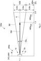
- the Fig. 2 also shows schematically and in side view an exemplary arrangement of a sensor system 200a of a security system 100a according to the invention, which comprises a motion detector 1a and a distance sensor 2a in a housing G.
- the sensor system 200a or the approximate center of the housing G is arranged on a wall W preferably at a mounting height MH of 1.1 m.
- a motion detection BE by the motion detector 1a takes place in an opening angle ⁇ w 1 of approx. 30 degrees and thus results in a motion detection nominal range NRw BE of approx. 2.0 m and a vertical detection range VEB of 0.5 m above and below an axis A at a height H of approx. 0.6 m.
- a distance measurement DM by the distance sensor 2a takes place linearly up to a distance measurement nominal range NRw DM of 1.3 m.
- the distance measurement DM corresponds to the axis A, but in principle the distance measurement DM can also take place in any other direction.
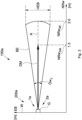
- the Fig.3 shows schematically the top view of the exemplary arrangement of the sensors 200a of the inventive security system 100a from the Fig. 2 .
- a detection width EB is now shown on the Y-axis, which, with an opening angle ⁇ w 2 of approximately 30 degrees, results in a horizontal detection range HEB of the motion detection BE or the motion detector 1a.
- FIG.4 A further embodiment of a security system 100b according to the invention is shown schematically, which basically has the same components, namely essentially, without listing all the connecting lines, interfaces and inputs and outputs, a motion detector 1b, a distance sensor 2b, a microcontroller 15a, a timer 16a and a communication module 36a.
- a sensor system 200b comprises the motion detector 1b and the distance sensor 2b.
- the communication module of the security system according to the invention comprises at least one WLAN module in addition to the GSM module and another version comprises at least one GPS module in addition to the GSM and WLAN modules.
- KNX and Ethernet modules are optional.
Landscapes
- Physics & Mathematics (AREA)
- General Physics & Mathematics (AREA)
- Business, Economics & Management (AREA)
- Emergency Management (AREA)
- Health & Medical Sciences (AREA)
- Engineering & Computer Science (AREA)
- General Health & Medical Sciences (AREA)
- Gerontology & Geriatric Medicine (AREA)
- Human Computer Interaction (AREA)
- Multimedia (AREA)
- Psychiatry (AREA)
- Psychology (AREA)
- Social Psychology (AREA)
- Computer Networks & Wireless Communication (AREA)
- Alarm Systems (AREA)
Claims (14)
- Système de sécurité (100) pour la détection de mouvement dans au moins une pièce, le système de sécurité (100) comprenant au moins un dispositif de détection (200) comprenant un détecteur de mouvement (1) et un capteur de distance (2) et où le capteur de distance est formé pour mesurer le mouvement et où le système de sécurité comprend un microcontrôleur qui est adapté pour comparer une première valeur réelle de distance du capteur de distance avec une deuxième valeur réelle de distance du capteur de distance, et, à partir de là, de générer un signal de mesure de distance (DmS), avec lequel au moins une minuterie (16) est déclenchée et, après l'écoulement d'un délai de temps (ZI), de générer un signal d'alarme interne au capteur, et où un module de communication (36) du système de sécurité (100) comprend au moins un module GSM, qui est adapté, déclenché par le système d'alarme interne au capteur, d'envoyer un texto d'urgence et où le module de communication (36) comprend au moins un module ethernet / WLAN et où le système de sécurité comprend une unité de réception et d'entrée externe (54), par exemple un smartphone, et où le détecteur de mouvement est formé, lors d'une détection de mouvement, pour envoyer un signal au microcontrôleur (15) et ainsi mettre en marche l'alimentation électrique du détecteur de distance (2).
- Système de sécurité (100) selon la revendication 1, caractérisé en ce qu'une valeur de seuil pour la valeur absolue du signal de mesure de distance (DmS) peut être introduite dans le microcontrôleur (15), en ce que le microcontrôleur (15) effectue un réglage de la valeur absolue du signal de mesure de distance (DmS) entre la valeur seuil et la valeur absolue du signal de mesure de distance (DmS) et déclenche la minuterie (16) en cas de dépassement de la valeur seuil.
- Système de sécurité (100) selon l'une quelconque des revendications précédentes, caractérisé en ce que le système de sécurité (100) comprend un réseau de plusieurs dispositifs de détection (200) qui peuvent être commandés conjointement avec l'unité d'entrée et de réception externe (54) et différentes fonctions peuvent être attribuées aux dispositifs de détection (200).
- Système de sécurité (100) selon l'une quelconque des revendications précédentes, caractérisées en ce que le module de communication (36) comprend, en plus des modules GSM et Ethernet/WLAN, au moins un module KNX, TCPIP, et/ou GPS.
- Système de sécurité (100) selon l'une quelconque des revendications précédentes, caractérisé en ce que le module de communication (36) comprend un module VoIP.
- Système de sécurité (100) selon l'une quelconque des revendications précédentes, caractérisé en ce que le système de sécurité (100) peut être commuté dans un mode absence ou vacances qui peut être désactivé automatiquement par une détection de mouvement par le détecteur de mouvement (1) ou par le capteur de distance (2) et qui peut être réactivé avec une temporisation.
- Système de sécurité (100) selon l'une quelconque des revendications précédentes, caractérisé en ce que le microcontrôleur (15) comprend une fonction de test avec une accélération du temps.
- Système de sécurité (100) selon l'une quelconque des revendications précédentes, caractérisé en ce que la minuterie (16) déclenche périodiquement le déroulement d'un autotest du système de sécurité (100) et en ce que les données de l'autotest peuvent être enregistrées dans une mémoire d'erreurs.
- Système de sécurité (100) selon l'une quelconque des revendications précédentes, caractérisé en ce que le système de sécurité (100) comprend un récepteur servant de passerelle pour d'autres composants d'alarme.
- Système de sécurité (100) selon l'une quelconque des revendications précédentes, caractérisé en ce que le système de sécurité (100) pour le déclenchement de l'alarme comprend un microphone et un logiciel de reconnaissance vocale qui est capable d'apprentissage et de personnalisation, où le déclenchement de l'alarme est de préférence sécurisé par des mots clés
- Système de sécurité (100) selon l'une quelconque des revendications précédentes, caractérisé en ce que le système de sécurité (100) comprend un interphone avec une fonction mains libres.
- Système de sécurité (100) selon l'une quelconque des revendications précédentes, caractérisé en ce que l'alimentation en énergie (52) comprend une batterie qui peut être chargée au moyen d'une boucle d'induction.
- Système de sécurité (100) selon l'une des revendications précédentes, caractérisé en ce que le système de sécurité (100) comprend une caméra et/ou un scanner pour capturer l'image d'occupation d'une boîte de comprimés.
- Procédé d'utilisation d'un système de sécurité (100) selon l'une quelconque des revendications précédentes, caractérisé en ce que les étapes de procédé suivantes sont exécutées :a) - détecter un mouvement au moyen du détecteur de mouvement (1) ;b) - mettre en marche le capteur de distance (2) en cas de détection d'un mouvement ;c) - effectuer une mesure de distance (DM) par rapport à l'objet ou à la personne en mouvement et transmettre un signal de mesure de distance (DmS) au microcontrôleur(15) ;d) - comparer le signal de mesure de distance (DmS) avec un valeur seuil ;e) - activer la minuterie (16) en cas de dépassement de la valeur seuil ;f) - déclencher une alarme côté capteur en cas de dépassement de la durée de l'alarme d'un intervalle de temps (ZI) prédéfini de la minuterie (16) ;g) - envoyer le SMS d'urgence par l'intermédiaire de l'enclenchement du module GSM.
Priority Applications (1)
| Application Number | Priority Date | Filing Date | Title |
|---|---|---|---|
| EP13840174.0A EP3025316B1 (fr) | 2012-10-29 | 2013-10-29 | Système de sécurité à fonction d'appel de secours intégrée |
Applications Claiming Priority (4)
| Application Number | Priority Date | Filing Date | Title |
|---|---|---|---|
| CH02166/12A CH707131B1 (de) | 2012-10-29 | 2012-10-29 | Sicherheitssystem mit integrierter Notruf-Funktion. |
| EP12007410.9A EP2725563A1 (fr) | 2012-10-29 | 2012-10-29 | Système de sécurité avec fonction d'appel d'urgence intégrée |
| EP13840174.0A EP3025316B1 (fr) | 2012-10-29 | 2013-10-29 | Système de sécurité à fonction d'appel de secours intégrée |
| PCT/IB2013/059752 WO2014068480A2 (fr) | 2012-10-29 | 2013-10-29 | Système de sécurité à fonction d'appel de secours intégrée |
Publications (3)
| Publication Number | Publication Date |
|---|---|
| EP3025316A2 EP3025316A2 (fr) | 2016-06-01 |
| EP3025316C0 EP3025316C0 (fr) | 2024-08-28 |
| EP3025316B1 true EP3025316B1 (fr) | 2024-08-28 |
Family
ID=50349655
Family Applications (1)
| Application Number | Title | Priority Date | Filing Date |
|---|---|---|---|
| EP13840174.0A Active EP3025316B1 (fr) | 2012-10-29 | 2013-10-29 | Système de sécurité à fonction d'appel de secours intégrée |
Country Status (2)
| Country | Link |
|---|---|
| EP (1) | EP3025316B1 (fr) |
| WO (1) | WO2014068480A2 (fr) |
Families Citing this family (2)
| Publication number | Priority date | Publication date | Assignee | Title |
|---|---|---|---|---|
| EP3065113B1 (fr) * | 2015-03-05 | 2020-06-10 | Gigaset Communications GmbH | Système de surveillance |
| CN106382959B (zh) * | 2016-10-26 | 2019-11-05 | 合肥移顺信息技术有限公司 | 一种地下车库环境检测及提醒方法及其装置 |
Citations (2)
| Publication number | Priority date | Publication date | Assignee | Title |
|---|---|---|---|---|
| US5781108A (en) * | 1995-11-14 | 1998-07-14 | Future Tech Systems, Inc. | Automated detection and monitoring (ADAM) |
| JP2002340540A (ja) * | 2001-05-16 | 2002-11-27 | Sumitomo Osaka Cement Co Ltd | 監視システム |
Family Cites Families (7)
| Publication number | Priority date | Publication date | Assignee | Title |
|---|---|---|---|---|
| US7242305B2 (en) * | 2004-04-09 | 2007-07-10 | General Electric Company | Device and method for monitoring movement within a home |
| US7502498B2 (en) * | 2004-09-10 | 2009-03-10 | Available For Licensing | Patient monitoring apparatus |
| GB2426851B (en) * | 2005-05-28 | 2007-07-18 | Martin Charles Adams | An occupant monitoring system for homes or offices |
| US7589637B2 (en) * | 2005-12-30 | 2009-09-15 | Healthsense, Inc. | Monitoring activity of an individual |
| US7345619B2 (en) | 2005-12-30 | 2008-03-18 | Valeo Raytheon Systems, Inc. | Generating event signals in a radar system |
| US9277878B2 (en) * | 2009-02-26 | 2016-03-08 | Tko Enterprises, Inc. | Image processing sensor systems |
| WO2012119903A1 (fr) * | 2011-03-04 | 2012-09-13 | Deutsche Telekom Ag | Procédé et système de détection de chute et de transmission d'une alarme |
-
2013
- 2013-10-29 EP EP13840174.0A patent/EP3025316B1/fr active Active
- 2013-10-29 WO PCT/IB2013/059752 patent/WO2014068480A2/fr not_active Ceased
Patent Citations (2)
| Publication number | Priority date | Publication date | Assignee | Title |
|---|---|---|---|---|
| US5781108A (en) * | 1995-11-14 | 1998-07-14 | Future Tech Systems, Inc. | Automated detection and monitoring (ADAM) |
| JP2002340540A (ja) * | 2001-05-16 | 2002-11-27 | Sumitomo Osaka Cement Co Ltd | 監視システム |
Non-Patent Citations (1)
| Title |
|---|
| ABUS GMBH & CO. KG: "ABUS Secvest IP Funkalarmzentrale Bedienungsanleitung", 2 March 2012 (2012-03-02), XP055380277, Retrieved from the Internet <URL:https://www.safetyline-erkes.de/app/download/5805114654/ABUS Secvest IP Zentrale.pdf> [retrieved on 20170609] * |
Also Published As
| Publication number | Publication date |
|---|---|
| EP3025316C0 (fr) | 2024-08-28 |
| EP3025316A2 (fr) | 2016-06-01 |
| WO2014068480A2 (fr) | 2014-05-08 |
| WO2014068480A3 (fr) | 2014-06-26 |
Similar Documents
| Publication | Publication Date | Title |
|---|---|---|
| CN209000182U (zh) | 一种独居监护系统 | |
| US10847008B2 (en) | Monitoring system and method | |
| EP3295436B1 (fr) | Procédé d'utilisation d'un appareil de nettoyage à déplacement autonome | |
| DE69921633T2 (de) | Steuerungssystem für gebäudeautomation, das mit menschlichen physiologischen signalen gesteuert ist. | |
| US6211783B1 (en) | Action control process of security alarm system | |
| EP1782406B1 (fr) | Dispositifs de surveillance | |
| EP1000421B1 (fr) | Systeme de surveillance d'urgence pour appartements | |
| EP2879104B2 (fr) | Dispositif auxiliaire pour un détecteur de danger configuré sous forme de détecteur ponctuel pour la surveillance du fonctionnement du détecteur de danger, agencement et utilisation d'un tel dispositif | |
| EP3516636B1 (fr) | Dispositif de surveillance audio | |
| CN105046883A (zh) | 监护告警系统及其方法 | |
| EP2672472B1 (fr) | Procédé et dispositif de surveillance de la mobilité momentanée de personnes dans des locaux privés ou publics | |
| EP3025316B1 (fr) | Système de sécurité à fonction d'appel de secours intégrée | |
| DE102016125199B4 (de) | Autonomes Haushaltsgerät und Sitz- oder Liegemöbel hierzu | |
| EP3765926B1 (fr) | Système de capteurs de bâtiment | |
| EP1376502A1 (fr) | Système de surveillance | |
| EP2494532B1 (fr) | Système d'alarme pour détecter et signaler des états spécifiques à l'environnement et aux installations | |
| CH707131B1 (de) | Sicherheitssystem mit integrierter Notruf-Funktion. | |
| CN204990616U (zh) | 监护告警系统 | |
| EP1795125B1 (fr) | Dispositif de surveillance de personnes agées ou handicapées en cas d'urgence | |
| EP2725563A1 (fr) | Système de sécurité avec fonction d'appel d'urgence intégrée | |
| EP4270347A2 (fr) | Système de sécurité | |
| EP1906370A2 (fr) | Système de surveillance et d'avertisseur de personnes | |
| CN110731785A (zh) | 一种老年人家居健康智能监测呼救系统 | |
| DE102017129185A1 (de) | Verfahren zum energieeffizienten Betrieb einer Schaltungsanordnung mit einem Annäherungssensor sowie Annäherungssensoren und Schaltungsanordnungen zum Durchführen dieses Verfahrens | |
| EP0849716A2 (fr) | Procédé et dispositif pour surveiller des personnes à risque avec alarme automatique |
Legal Events
| Date | Code | Title | Description |
|---|---|---|---|
| PUAI | Public reference made under article 153(3) epc to a published international application that has entered the european phase |
Free format text: ORIGINAL CODE: 0009012 |
|
| 17P | Request for examination filed |
Effective date: 20150916 |
|
| AK | Designated contracting states |
Kind code of ref document: A2 Designated state(s): AL AT BE BG CH CY CZ DE DK EE ES FI FR GB GR HR HU IE IS IT LI LT LU LV MC MK MT NL NO PL PT RO RS SE SI SK SM TR |
|
| STAA | Information on the status of an ep patent application or granted ep patent |
Free format text: STATUS: EXAMINATION IS IN PROGRESS |
|
| 17Q | First examination report despatched |
Effective date: 20170620 |
|
| STAA | Information on the status of an ep patent application or granted ep patent |
Free format text: STATUS: THE APPLICATION IS DEEMED TO BE WITHDRAWN |
|
| R18D | Application deemed to be withdrawn (corrected) |
Effective date: 20191022 |
|
| 18RA | Request filed for re-establishment of rights before grant |
Effective date: 20200602 |
|
| RAP3 | Party data changed (applicant data changed or rights of an application transferred) |
Owner name: SCHORI, MARKUS |
|
| RIN1 | Information on inventor provided before grant (corrected) |
Inventor name: SCHORI, MARKUS |
|
| STAA | Information on the status of an ep patent application or granted ep patent |
Free format text: STATUS: EXAMINATION IS IN PROGRESS |
|
| D18D | Application deemed to be withdrawn (deleted) | ||
| GRAP | Despatch of communication of intention to grant a patent |
Free format text: ORIGINAL CODE: EPIDOSNIGR1 |
|
| STAA | Information on the status of an ep patent application or granted ep patent |
Free format text: STATUS: GRANT OF PATENT IS INTENDED |
|
| INTG | Intention to grant announced |
Effective date: 20240320 |
|
| GRAS | Grant fee paid |
Free format text: ORIGINAL CODE: EPIDOSNIGR3 |
|
| GRAA | (expected) grant |
Free format text: ORIGINAL CODE: 0009210 |
|
| STAA | Information on the status of an ep patent application or granted ep patent |
Free format text: STATUS: THE PATENT HAS BEEN GRANTED |
|
| AK | Designated contracting states |
Kind code of ref document: B1 Designated state(s): AL AT BE BG CH CY CZ DE DK EE ES FI FR GB GR HR HU IE IS IT LI LT LU LV MC MK MT NL NO PL PT RO RS SE SI SK SM TR |
|
| REG | Reference to a national code |
Ref country code: CH Ref legal event code: EP |
|
| REG | Reference to a national code |
Ref country code: DE Ref legal event code: R096 Ref document number: 502013016538 Country of ref document: DE |
|
| REG | Reference to a national code |
Ref country code: IE Ref legal event code: FG4D Free format text: LANGUAGE OF EP DOCUMENT: GERMAN |
|
| U01 | Request for unitary effect filed |
Effective date: 20240927 |
|
| U07 | Unitary effect registered |
Designated state(s): AT BE BG DE DK EE FI FR IT LT LU LV MT NL PT RO SE SI Effective date: 20241016 |
|
| U20 | Renewal fee for the european patent with unitary effect paid |
Year of fee payment: 12 Effective date: 20241022 |
|
| PG25 | Lapsed in a contracting state [announced via postgrant information from national office to epo] |
Ref country code: NO Free format text: LAPSE BECAUSE OF FAILURE TO SUBMIT A TRANSLATION OF THE DESCRIPTION OR TO PAY THE FEE WITHIN THE PRESCRIBED TIME-LIMIT Effective date: 20241128 |
|
| PG25 | Lapsed in a contracting state [announced via postgrant information from national office to epo] |
Ref country code: GR Free format text: LAPSE BECAUSE OF FAILURE TO SUBMIT A TRANSLATION OF THE DESCRIPTION OR TO PAY THE FEE WITHIN THE PRESCRIBED TIME-LIMIT Effective date: 20241129 Ref country code: PL Free format text: LAPSE BECAUSE OF FAILURE TO SUBMIT A TRANSLATION OF THE DESCRIPTION OR TO PAY THE FEE WITHIN THE PRESCRIBED TIME-LIMIT Effective date: 20240828 |
|
| PG25 | Lapsed in a contracting state [announced via postgrant information from national office to epo] |
Ref country code: IS Free format text: LAPSE BECAUSE OF FAILURE TO SUBMIT A TRANSLATION OF THE DESCRIPTION OR TO PAY THE FEE WITHIN THE PRESCRIBED TIME-LIMIT Effective date: 20241228 |
|
| PG25 | Lapsed in a contracting state [announced via postgrant information from national office to epo] |
Ref country code: HR Free format text: LAPSE BECAUSE OF FAILURE TO SUBMIT A TRANSLATION OF THE DESCRIPTION OR TO PAY THE FEE WITHIN THE PRESCRIBED TIME-LIMIT Effective date: 20240828 |
|
| PG25 | Lapsed in a contracting state [announced via postgrant information from national office to epo] |
Ref country code: RS Free format text: LAPSE BECAUSE OF FAILURE TO SUBMIT A TRANSLATION OF THE DESCRIPTION OR TO PAY THE FEE WITHIN THE PRESCRIBED TIME-LIMIT Effective date: 20241128 Ref country code: ES Free format text: LAPSE BECAUSE OF FAILURE TO SUBMIT A TRANSLATION OF THE DESCRIPTION OR TO PAY THE FEE WITHIN THE PRESCRIBED TIME-LIMIT Effective date: 20240828 |
|
| PG25 | Lapsed in a contracting state [announced via postgrant information from national office to epo] |
Ref country code: RS Free format text: LAPSE BECAUSE OF FAILURE TO SUBMIT A TRANSLATION OF THE DESCRIPTION OR TO PAY THE FEE WITHIN THE PRESCRIBED TIME-LIMIT Effective date: 20241128 Ref country code: PL Free format text: LAPSE BECAUSE OF FAILURE TO SUBMIT A TRANSLATION OF THE DESCRIPTION OR TO PAY THE FEE WITHIN THE PRESCRIBED TIME-LIMIT Effective date: 20240828 Ref country code: NO Free format text: LAPSE BECAUSE OF FAILURE TO SUBMIT A TRANSLATION OF THE DESCRIPTION OR TO PAY THE FEE WITHIN THE PRESCRIBED TIME-LIMIT Effective date: 20241128 Ref country code: IS Free format text: LAPSE BECAUSE OF FAILURE TO SUBMIT A TRANSLATION OF THE DESCRIPTION OR TO PAY THE FEE WITHIN THE PRESCRIBED TIME-LIMIT Effective date: 20241228 Ref country code: HR Free format text: LAPSE BECAUSE OF FAILURE TO SUBMIT A TRANSLATION OF THE DESCRIPTION OR TO PAY THE FEE WITHIN THE PRESCRIBED TIME-LIMIT Effective date: 20240828 Ref country code: GR Free format text: LAPSE BECAUSE OF FAILURE TO SUBMIT A TRANSLATION OF THE DESCRIPTION OR TO PAY THE FEE WITHIN THE PRESCRIBED TIME-LIMIT Effective date: 20241129 Ref country code: ES Free format text: LAPSE BECAUSE OF FAILURE TO SUBMIT A TRANSLATION OF THE DESCRIPTION OR TO PAY THE FEE WITHIN THE PRESCRIBED TIME-LIMIT Effective date: 20240828 |
|
| PG25 | Lapsed in a contracting state [announced via postgrant information from national office to epo] |
Ref country code: SM Free format text: LAPSE BECAUSE OF FAILURE TO SUBMIT A TRANSLATION OF THE DESCRIPTION OR TO PAY THE FEE WITHIN THE PRESCRIBED TIME-LIMIT Effective date: 20240828 |
|
| PG25 | Lapsed in a contracting state [announced via postgrant information from national office to epo] |
Ref country code: CZ Free format text: LAPSE BECAUSE OF FAILURE TO SUBMIT A TRANSLATION OF THE DESCRIPTION OR TO PAY THE FEE WITHIN THE PRESCRIBED TIME-LIMIT Effective date: 20240828 |
|
| PG25 | Lapsed in a contracting state [announced via postgrant information from national office to epo] |
Ref country code: SK Free format text: LAPSE BECAUSE OF FAILURE TO SUBMIT A TRANSLATION OF THE DESCRIPTION OR TO PAY THE FEE WITHIN THE PRESCRIBED TIME-LIMIT Effective date: 20240828 |
|
| PLBE | No opposition filed within time limit |
Free format text: ORIGINAL CODE: 0009261 |
|
| STAA | Information on the status of an ep patent application or granted ep patent |
Free format text: STATUS: NO OPPOSITION FILED WITHIN TIME LIMIT |
|
| PG25 | Lapsed in a contracting state [announced via postgrant information from national office to epo] |
Ref country code: MC Free format text: LAPSE BECAUSE OF FAILURE TO SUBMIT A TRANSLATION OF THE DESCRIPTION OR TO PAY THE FEE WITHIN THE PRESCRIBED TIME-LIMIT Effective date: 20240828 |
|
| GBPC | Gb: european patent ceased through non-payment of renewal fee |
Effective date: 20241128 |
|
| 26N | No opposition filed |
Effective date: 20250530 |
|
| PG25 | Lapsed in a contracting state [announced via postgrant information from national office to epo] |
Ref country code: GB Free format text: LAPSE BECAUSE OF NON-PAYMENT OF DUE FEES Effective date: 20241128 |
|
| PG25 | Lapsed in a contracting state [announced via postgrant information from national office to epo] |
Ref country code: IE Free format text: LAPSE BECAUSE OF NON-PAYMENT OF DUE FEES Effective date: 20241029 |
|
| REG | Reference to a national code |
Ref country code: CH Ref legal event code: U11 Free format text: ST27 STATUS EVENT CODE: U-0-0-U10-U11 (AS PROVIDED BY THE NATIONAL OFFICE) Effective date: 20251101 |
|
| U20 | Renewal fee for the european patent with unitary effect paid |
Year of fee payment: 13 Effective date: 20251013 |
|
| U1N | Appointed representative for the unitary patent procedure changed after the registration of the unitary effect |
Representative=s name: FRISCHKNECHT, HARRY RALPH; CH |
|
| PGFP | Annual fee paid to national office [announced via postgrant information from national office to epo] |
Ref country code: CH Payment date: 20251101 Year of fee payment: 13 |
|
| PG25 | Lapsed in a contracting state [announced via postgrant information from national office to epo] |
Ref country code: HU Free format text: LAPSE BECAUSE OF FAILURE TO SUBMIT A TRANSLATION OF THE DESCRIPTION OR TO PAY THE FEE WITHIN THE PRESCRIBED TIME-LIMIT; INVALID AB INITIO Effective date: 20131029 |
|
| PG25 | Lapsed in a contracting state [announced via postgrant information from national office to epo] |
Ref country code: CY Free format text: LAPSE BECAUSE OF FAILURE TO SUBMIT A TRANSLATION OF THE DESCRIPTION OR TO PAY THE FEE WITHIN THE PRESCRIBED TIME-LIMIT; INVALID AB INITIO Effective date: 20131029 |