EP3025323B1 - Kennzeichnungsvorrichtung mit einem haken für einen handelsartikel - Google Patents
Kennzeichnungsvorrichtung mit einem haken für einen handelsartikel Download PDFInfo
- Publication number
- EP3025323B1 EP3025323B1 EP14790151.6A EP14790151A EP3025323B1 EP 3025323 B1 EP3025323 B1 EP 3025323B1 EP 14790151 A EP14790151 A EP 14790151A EP 3025323 B1 EP3025323 B1 EP 3025323B1
- Authority
- EP
- European Patent Office
- Prior art keywords
- tip
- free end
- axial
- coupling part
- housing
- Prior art date
- Legal status (The legal status is an assumption and is not a legal conclusion. Google has not performed a legal analysis and makes no representation as to the accuracy of the status listed.)
- Active
Links
Images




Classifications
-
- E—FIXED CONSTRUCTIONS
- E05—LOCKS; KEYS; WINDOW OR DOOR FITTINGS; SAFES
- E05B—LOCKS; ACCESSORIES THEREFOR; HANDCUFFS
- E05B73/00—Devices for locking portable objects against unauthorised removal; Miscellaneous locking devices
- E05B73/0017—Anti-theft devices, e.g. tags or monitors, fixed to articles, e.g. clothes, and to be removed at the check-out of shops
-
- E—FIXED CONSTRUCTIONS
- E05—LOCKS; KEYS; WINDOW OR DOOR FITTINGS; SAFES
- E05B—LOCKS; ACCESSORIES THEREFOR; HANDCUFFS
- E05B73/00—Devices for locking portable objects against unauthorised removal; Miscellaneous locking devices
- E05B73/0017—Anti-theft devices, e.g. tags or monitors, fixed to articles, e.g. clothes, and to be removed at the check-out of shops
- E05B73/0029—Tags wrapped around the protected product using cables, wires or the like, e.g. with cable retraction for tensioning
-
- E—FIXED CONSTRUCTIONS
- E05—LOCKS; KEYS; WINDOW OR DOOR FITTINGS; SAFES
- E05B—LOCKS; ACCESSORIES THEREFOR; HANDCUFFS
- E05B39/00—Locks giving indication of authorised or unauthorised unlocking
- E05B39/002—Locks giving indication of authorised or unauthorised unlocking by releasing a liquid, e.g. ill-smelling or dye
-
- E—FIXED CONSTRUCTIONS
- E05—LOCKS; KEYS; WINDOW OR DOOR FITTINGS; SAFES
- E05B—LOCKS; ACCESSORIES THEREFOR; HANDCUFFS
- E05B39/00—Locks giving indication of authorised or unauthorised unlocking
- E05B39/005—Locks with means for tracking the location of locked items, e.g. freight containers
-
- E—FIXED CONSTRUCTIONS
- E05—LOCKS; KEYS; WINDOW OR DOOR FITTINGS; SAFES
- E05B—LOCKS; ACCESSORIES THEREFOR; HANDCUFFS
- E05B67/00—Padlocks; Details thereof
- E05B67/06—Shackles; Arrangement of the shackle
- E05B67/08—Padlocks with shackles hinged on the case
- E05B67/10—Padlocks with shackles hinged on the case with devices for securing the free end of the shackle
-
- G—PHYSICS
- G08—SIGNALLING
- G08B—SIGNALLING SYSTEMS, e.g. PERSONAL CALLING SYSTEMS; ORDER TELEGRAPHS; ALARM SYSTEMS
- G08B13/00—Burglar, theft or intruder alarms
- G08B13/22—Electrical actuation
- G08B13/24—Electrical actuation by interference with electromagnetic field distribution
- G08B13/2402—Electronic Article Surveillance [EAS], i.e. systems using tags for detecting removal of a tagged item from a secure area, e.g. tags for detecting shoplifting
- G08B13/2428—Tag details
- G08B13/2434—Tag housing and attachment details
-
- G—PHYSICS
- G09—EDUCATION; CRYPTOGRAPHY; DISPLAY; ADVERTISING; SEALS
- G09F—DISPLAYING; ADVERTISING; SIGNS; LABELS OR NAME-PLATES; SEALS
- G09F3/00—Labels, tag tickets, or similar identification or indication means; Seals; Postage or like stamps
- G09F3/02—Forms or constructions
- G09F3/03—Forms or constructions of security seals
- G09F3/0305—Forms or constructions of security seals characterised by the type of seal used
-
- G—PHYSICS
- G09—EDUCATION; CRYPTOGRAPHY; DISPLAY; ADVERTISING; SEALS
- G09F—DISPLAYING; ADVERTISING; SIGNS; LABELS OR NAME-PLATES; SEALS
- G09F3/00—Labels, tag tickets, or similar identification or indication means; Seals; Postage or like stamps
- G09F3/02—Forms or constructions
- G09F3/03—Forms or constructions of security seals
- G09F3/0305—Forms or constructions of security seals characterised by the type of seal used
- G09F3/0329—Forms or constructions of security seals characterised by the type of seal used having electronic sealing means
- G09F3/0335—Forms or constructions of security seals characterised by the type of seal used having electronic sealing means using RFID tags
-
- G—PHYSICS
- G09—EDUCATION; CRYPTOGRAPHY; DISPLAY; ADVERTISING; SEALS
- G09F—DISPLAYING; ADVERTISING; SIGNS; LABELS OR NAME-PLATES; SEALS
- G09F3/00—Labels, tag tickets, or similar identification or indication means; Seals; Postage or like stamps
- G09F3/02—Forms or constructions
- G09F3/03—Forms or constructions of security seals
- G09F3/0305—Forms or constructions of security seals characterised by the type of seal used
- G09F3/0347—Forms or constructions of security seals characterised by the type of seal used having padlock-type sealing means
-
- G—PHYSICS
- G09—EDUCATION; CRYPTOGRAPHY; DISPLAY; ADVERTISING; SEALS
- G09F—DISPLAYING; ADVERTISING; SIGNS; LABELS OR NAME-PLATES; SEALS
- G09F3/00—Labels, tag tickets, or similar identification or indication means; Seals; Postage or like stamps
- G09F3/02—Forms or constructions
- G09F3/03—Forms or constructions of security seals
- G09F3/0376—Forms or constructions of security seals using a special technique to detect tampering, e.g. by ultrasonic or optical means
-
- G—PHYSICS
- G09—EDUCATION; CRYPTOGRAPHY; DISPLAY; ADVERTISING; SEALS
- G09F—DISPLAYING; ADVERTISING; SIGNS; LABELS OR NAME-PLATES; SEALS
- G09F3/00—Labels, tag tickets, or similar identification or indication means; Seals; Postage or like stamps
- G09F3/08—Fastening or securing by means not forming part of the material of the label itself
- G09F3/12—Fastening or securing by means not forming part of the material of the label itself by pins, staples, or the like
-
- G—PHYSICS
- G09—EDUCATION; CRYPTOGRAPHY; DISPLAY; ADVERTISING; SEALS
- G09F—DISPLAYING; ADVERTISING; SIGNS; LABELS OR NAME-PLATES; SEALS
- G09F3/00—Labels, tag tickets, or similar identification or indication means; Seals; Postage or like stamps
- G09F3/08—Fastening or securing by means not forming part of the material of the label itself
- G09F3/14—Fastening or securing by means not forming part of the material of the label itself by strings, straps, chains, or wires
-
- G—PHYSICS
- G09—EDUCATION; CRYPTOGRAPHY; DISPLAY; ADVERTISING; SEALS
- G09F—DISPLAYING; ADVERTISING; SIGNS; LABELS OR NAME-PLATES; SEALS
- G09F3/00—Labels, tag tickets, or similar identification or indication means; Seals; Postage or like stamps
- G09F3/08—Fastening or securing by means not forming part of the material of the label itself
- G09F3/18—Casings, frames or enclosures for labels
- G09F3/20—Casings, frames or enclosures for labels for adjustable, removable, or interchangeable labels
- G09F3/207—Casings, frames or enclosures for labels for adjustable, removable, or interchangeable labels in the form of a badge to be worn by a person
-
- G—PHYSICS
- G09—EDUCATION; CRYPTOGRAPHY; DISPLAY; ADVERTISING; SEALS
- G09F—DISPLAYING; ADVERTISING; SIGNS; LABELS OR NAME-PLATES; SEALS
- G09F7/00—Signs, name or number plates, letters, numerals, or symbols; Panels or boards
- G09F7/02—Signs, plates, panels or boards using readily-detachable elements bearing or forming symbols
- G09F7/06—Signs, plates, panels or boards using readily-detachable elements bearing or forming symbols the elements being secured or adapted to be secured by means of pins and holes
Definitions
- the invention relates to a device for marking a commercial article.
- Such devices generally comprise two parts including a first portion which has a tip for insertion into an orifice of a second part.
- the second portion includes means for locking the tip to prevent its removal once it has been inserted into the orifice.
- Such a device is more particularly used by piercing the commercial article with the tip of the first part and inserting this tip in the orifice of the second part to lock it there.
- the article is thus imprisoned between the two parts of the device until it passes to the cash register of the store.
- the device may carry identifying / marking information of the article such as information about the article and / or the trade mark under which it is sold.
- the device may include one or more security devices against theft. This or these bodies cooperate for example with gantries located at the entrances and exits of the store to detect any attempt to exit the store article fraud and to issue an alarm.
- these devices are not however adapted to be fixed to items that are not suitable for piercing or bit by a tip, such as sports shoes, leather goods such as belts, handbags. ..
- US 6,052,876 discloses (the reference of the relevant passages in parentheses): a marking device (15) for a packaged or unpackaged commercial article, the device comprising an axial point (17) and a rigid fastening member (8) intended for the hooking the device to an article in its packaging, the fastening member comprising a body provided with a first free end (cf. Fig. 5 ) and an opposite second end (10, 11) hingedly but non-permanently attached to the device.
- US 2008/3033670 discloses a device for marking a packaged or unpackaged commercial article, the device comprising an axial point (3) and a non-rigid fastening member (1) intended to hook the device to a commercial article or to its packaging , the fastening member comprising a body (10) provided with a first free end (15) and a second opposite end (12) fixedly and permanently fixed to the device, the first free end being able to pivot around the second end, between a first position in which the first free end is remote from the device and a second position in which the first free end is releasably connected to the axial tip (3) of the device.
- This device can thus retain the same principle of a two-part marking device of the prior art and be fixed or hooked in a locked manner to a commercial item without the tip does not perforate the article or its packaging.
- the part of the device which is not the attachment part may for example not be modified with respect to a device of the prior art, only the attachment part requiring specific means (fastener) to fill the aforementioned function.
- the attachment portion is relatively simple design because it does not use an additional mechanism to prevent the end of the fastener to leave the housing. Indeed, it is the other part of the marking device which, when positioned in front of the housing in position locked with the attachment portion (via conventional locking / holding means), prevents the free end of the latching member from coming out of the housing.
- Unlocking the two parts is done conventionally with a known tool such as a permanent magnet.
- a known tool such as a permanent magnet.
- the tool or the unlocking system may be different from that mentioned above and of a type known in the field of anti-theft devices.
- the body of the fastening member can surround a portion of an article (eg: belt buckle, bag strap, eyelet). 'a shoe, buttonhole ...) thanks to the first free end of the organ.
- an article eg: belt buckle, bag strap, eyelet. 'a shoe, buttonhole
- the first free end of the member rotates relative to the attachment portion and, in particular, the second fixed end of the member, to enter the housing which it is reserved for him. This allows to imprison the portion of the article within the loop formed by the body of the member which is arranged externally to the attachment portion.
- the loop thus formed is closed, which prevents the portion of the article from emerging from the loop and to release.
- the other part of the device is then approached to the attachment portion and the axial tip is inserted axially into the orifice until the tip locking means prevent axial removal of the inserted tip.
- the device according to the invention is particularly simple to design and implement.
- the fastening member which is rotatable relative to the attachment portion is permanently connected to the attachment portion by its second end.
- the user can not remove this second end which is mounted so as to be trapped inside the attachment part.
- the snap of an article can be done simply, with only one hand holding the hooking portion and the first free end in a position away from the latter (latching member in the open position).
- the user rotates the latching member by bringing the first free end against the latching portion with the article trapped in the loop formed by the body (closed position).
- the attachment portion which pivots alone, or even the attachment portion and the attachment member towards each other.
- the implementation therefore requires few operations and these are particularly simple.
- the pivoting movement of the fastening member is simply because it is guided by the design of the rigid fastening member and its mobility relative to the fastening member. The user does not have to aim the housing to introduce the free end of the fastener.
- the user can simply manipulate the body of the external member to the attachment portion to ensure the pivoting movement with one hand. He does not have to put his finger near the point.
- the housing being remote from the tip, even if the user presses the free end of the body to introduce it into its housing, it is not likely to hurt on the tip.
- the rigid coupling member is of purely mechanical design.
- the rigid member is for example made of a wire, for example hardened steel (such as hooks or padlock handles).
- the subject of the invention is a device for marking a packaged or non-packaged commercial article, the device comprising an axial point and a rigid fastening member intended to hook the device to a commercial article. or in its packaging, the attachment member comprising a body provided with a first free end and an opposite second end fixedly and permanently fixed to the device, the first free end being able to pivot about the second end; between a first position in which the first free end is remote from the device and a second position in which the first free end is disposed in a housing of the device which is remote from the axial point, the first free end being able to freely pass through position to another during its pivoting movement.
- This device corresponds to the attachment portion of the marking device according to the invention and has the same characteristics and advantages which will not be repeated here.
- the axial point is intended to cooperate and to lock with a complementary device of the marking device of known type for example, the first free end being able to move freely from one position to the other as long as the axial point does not cooperate with said complementary device.
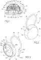
- the body 18 of the device 10 encloses a central cavity 19 in which are disposed the aforementioned ball locking means or other known locking means.
- Several balls 19a are placed in a funnel part 19b inside the cavity, in the same plane and form between them a central space for receiving the tip 14.
- the body also comprises a plate or plate 19c, for example substantially plane which closes the access to the inner portion of the body.
- the central insertion orifice 20 of the tip is formed in the plate 19c. When the tip is inserted in this hole and in the inter-ball central space, the balls are wedged in the convergent portion of the funnel.
- the balls are mounted on a support 19d of non-magnetic material, which is mounted on elastic means of non-magnetic material, such as a spring 19e.
- the elastic means exert on the support 19d and thus on the balls an axial force which tends to push them further into the narrowest part of the funnel 19b.
- the balls are made of a magnetic material.
- Unlocking the tip and thus the decoupling or disassembly of the two parts 12 and 16 can only be performed by an unlocking tool, called decoupler, which comprises at least one permanent magnet.
- the balls can be extracted from the convergent portion of the funnel under the action of the external magnetic field generated by the permanent magnet when the alignment axis of the funnel, balls and elastic means coincides with the axis of the magnetic field.
- the second part 16 is identical to that of a conventional device marketed by the company. EXAQTWORLD and which is for example described in the French patent application no. 2,947,087 .
- the device 10 is for example a marking device or identification of the article to which it is attached and comprises, for this purpose, identification information of the article, or price.
- This information is carried by the device and have for example been registered / printed on it or on a reported element (eg label, film ...) on the device or integrated therewith.
- the information may be protected by a transparent protective interface such as an adhesive film, a window or a hood mounted on the device.
- the device may, additionally or alternatively, include an optical reading code such as a flash code representative of information about the article, the trade mark under which it is sold, the store or the chain of stores where it is sold.
- an optical reading code such as a flash code representative of information about the article, the trade mark under which it is sold, the store or the chain of stores where it is sold.
- the code is for example representative of the address of a site or a web page in relation to the above information.
- the identification information is for example carried by the attachment portion 12.
- the device 10 is also, in the present embodiment, an anti-theft device or badge which is lockedly attached to an article to prevent its theft in the store.
- the body 18 also comprises at the periphery of the central cavity 19 an annular chamber 19f in which is arranged a member 23, or more organs, for example passive.
- a passive member is adapted to receive electromagnetic waves from a source external to the device.
- Such a member may for example take the form of a LC type resonant circuit.
- the body 18 may contain one or more active organs, that is to say which are capable of emitting electromagnetic waves to the outside of the device and to receive.
- active or passive elements are, for example, coils with ferrite, with or without a capacitor, LCR circuits, magnetic filaments, RFID or NFC circuits with an active or passive memory chip, electronic micro-sensors.
- a detection system such as a gantry or antenna, placed at an access point of the store where the article is sold. protect, to trigger an alarm when the device is detected at the access point.
- the presence of this or these organs provides an additional anti-theft function to the identification / marking device. However, this function is only optional for the implementation of the invention.
- this or these organs are arranged in the attachment portion 12 of the device.
- the body 18 has a generally hemispherical shape, that is to say curved on a face 18a and substantially flat on the opposite face 18b which is the outer face of the plate 19c.
- the attachment portion 12 illustrated in perspective at the figure 3 (Separate from the portion 16) comprises a body 30, for example in the general form of disc, having two opposite faces 30a, 30b, of which only the inner face 30a is shown in this figure.
- the outer face 30b is represented on the figure 1 .
- the head of the tip 14 is housed in the body 30 ( figure 1 ) and extends perpendicular to the face 30a away from it along the axis of said tip ( figure 3 ).
- the body 30 has an axial extension or annular flange 30c which extends at the periphery of the face 30a so as to form a central recess 30d open around the tip 14 and which is bordered by the flange 30c.
- this recess 30d correspond to the external dimensions (eg diameter) of the second part 16 so as to allow the latter to be inserted into the recess as illustrated in FIG. figure 1 .
- the tip 14 is locked in the body 18 of the second part 16 and the two faces 18b and 30a are vis-à-vis and against each other or, in any case, as close as possible.
- annular rim or skirt 30c extends along a portion of the outer wall (face 18a) of the second portion 16 and therefore beyond the interface zone between the respective two faces 18b and 30a facing each other. two parts.
- annular rim 30c protects access to this interface zone and prevents the introduction of a tool / object between the two faces 18b and 30a and which would aim to break the tip.
- axial extension 30c is optional.
- the attachment part 12 illustrated at figure 3 also comprises a hooking member 32 which has a substantially hook-like appearance and is movably mounted on the body 30.
- the attachment member 32 is shown in isolation to the figure 4 .
- It comprises a body that has two opposite ends 32a and 32b.
- the member 32 comprises a first portion which is formed by the two opposite ends 32a, 32b substantially rectilinear and spaced apart from each other.
- Both ends 32a and 32b are enclosed within the body 30 of the attachment portion 12 and inaccessible from the outside when the device is locked ( Figures 1 and 2 ).
- the member 32 comprises a second curved portion 38 forming the body of the member and which extends from the two opposite ends 32a, 32b by bringing them together.
- the second bent portion 38 has substantially an arcuate shape that extends over more than 180 ° and in the same plane as that of the two ends 32a, 32b.
- the bent portion 38 has a substantially identical diameter to that of the body 30. However, this diameter can be reduced or increased as needed.
- the circular shape can also be modified and be for example elliptical or, in general, adopt a curved or non-curved shape, regular (eg rectangular or square) or not.
- the first end 32a ( figures 3 and 4 ), said free, mainly comprises a rectilinear section 32a1 which extends from the second curved portion 38 to an end portion 32a2.
- This end portion 32a2 is bent perpendicularly to the plane containing the two ends 32a, 32b and the bent portion 38.
- the second end 32b comprises a rectilinear section 32b1, parallel to the section 32a1, which extends from the second curved portion 38 to an end portion 32b2.
- the end portion 32b2 is separated from the section 32b1 by a groove or necking 32b3.
- the figure 5 (axial section of the attachment portion 12) shows the arrangement of the second end 32b in an axial cavity 40 of the body 30 of the attachment portion 12. This cavity is perpendicular to the axis of the tip 14 and is open at one end 40a for the passage of the end 32b1.
- the cavity 40 is also laterally open, near its opposite end 40b, in a zone 40c of enlarged diameter which is provided to receive an axial retaining assembly of the end 32b in its cavity.
- This assembly comprises a washer 42 arranged in the groove 32b3 and a sleeve 44 disposed around the end zone 32b which is adjacent to the groove 32b3 (this zone is disposed between the groove 32b3 and the end 40a) and therefore to the washer 42.
- the assembly 42, 44 thus mounted is disposed opposite the lateral opening 40d which allows this assembly.
- This set of very simple design prevents the withdrawal of the end 32b of the cavity 40 along the axis thereof (this axis also forms the axis of rotation of the member 32) but allows its rotation around it -Even within said cavity to allow pivoting of the attachment member (and its first end 32a) from one position to another.
- the attachment member is for example made from a wire which is shaped by folding so as to adopt the desired hook shape.
- the metal is, for example, hardened steel of the type used for padlocks.
- the diameter of the wire varies from 2 to 3 mm and is for example equal to 2 mm.
- a housing 50 is arranged in the body 30 of the attachment part 12 ( figure 3 ) at a distance from the axial point 14.
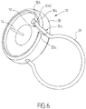
- This housing makes it possible to receive the first end 32a of the attachment member 32 (FIG. figure 6 ) after pivoting thereof about the second end 32b (this end constitutes a pivot axis) which is hingedly attached to the hooking portion ( figure 5 ). Pivoting is effected freely between a first position in which the first end 32a is moved away from the body 30 ( figure 3 ) and a second position in which the first end 32a is disposed in the housing 50 ( figure 6 ). Pivoting takes place in a plane perpendicular to the face of the attachment portion from which extends the axial point 14 (this plane contains the axial point). In the absence of the portion 16 the first end 32a can freely come out of its housing and return to leisure in its first position.
- the housing 50 is in the form of an axial notch formed over the entire thickness of the body and which opens out at its outer circumference ( Figures 1 and 3 ) by an open end 50a.
- the notch is also open on the inner face 30a so that the first end 32a can enter.
- the annular flange 30c is interrupted locally by this notch ( figures 3 and 6 ).
- the notch 50 has, near the opposite end 50b, in the bottom wall of the notch which is parallel to the inner face 30a, a recess 50c. This recess is intended to receive the curved end portion 32a2 in the second position of the attachment member 32 ( figure 6 ). This arrangement thus prevents the axial shrinkage (the axis here is the axis of the housing) in force from the first end 32a out of its housing 50.
- the cavity 40 and the housing 50 are mutually parallel to receive respectively the second end 32b and the first end 32a.
- the attachment part 12 ( figure 1 ) also comprises a cover 52, for example transparent, which is inserted into the body 30, inside an inner zone delimited by a second annular rim 30e.
- the second flange 30e extends in a direction opposite that of the first flange 30c.
- the cover 52 defines with the rear face 30f of the body 30, opposite the inner front face 30a, a partially hollow space.
- the hood is nested or screwed or otherwise removably secured to the body 30 to access the rear face 30f, for example to assemble / disassemble the axial retention assembly of the figure 5 (the hood is not shown on the figure 5 for the sake of simplification).
- the space behind the cover 52 makes it possible, for example, to house an insert carrying information as described in the French patent no. 2,947,087 .
- the free end 32a of the fastening member is spaced from the body 30 (first open position identical to that of the figure 3 ).
- the first free end 32a is introduced for example inside the loop 62 of the belt to emerge on the other side to imprison, inside the curved portion 38 (body of the organ), loop 62 ( figure 7b ).
- the body 30 then pivots, as indicated by the arrow marked P, around the pivot axis marked in dotted lines by the axis A1 (second end 32b of the attachment member 32), so that the first free end 32a enters the housing 50.
- the Figure 7c is a view taken from the opposite side to the view from the figure 7b after pivoting.
- This first phase is particularly simple to perform and fast and can possibly be performed with one hand.
- the second part 16 of the device is brought against the first attachment portion 12.
- the axial insertion orifice 20 of the second part is positioned in position. vis-à-vis the axial tip 14 and is pressed on the tip until the locking of the tip through the conventional locking means 22 described above.
- This second phase (blocking) is also particularly simple and quick to perform.
- the second part 16 is fitted inside the hollow or recess 30d formed on the inner face of the first part 12.
- the face 18b of the second part is thus brought into abutment against the inner face (front) 30a of the first part part 12, at least in the region of the opening of the housing 50 which opens on the face 30a.
- the first free end 32a is thus locked in its housing by the face 18b of the second part 16 which is itself locked to the first part 12 by the locking means.
- this tip 14 is no longer used to perforate the articles but only to fit in the orifice 20 of the second part, this tip no longer needs to be as pointed as before. It can therefore be blunt while being as thin as before, which can be easily achieved from a second conventional portion 16 that would be "recycled” for the purposes of the present invention.
- the tip is blunt also to avoid scratching the article inadvertently during the various manipulations.
- the tip can be designed from the beginning by being thinner than before.
- the tip 14 is carried by the second portion 16, while the tip insertion hole is arranged in the first portion 12 which further carries the locking means of the tip.
- the structure of the first attachment portion is modified accordingly and, in particular, the thickness of the body 30 is increased to accommodate the tip and the locking means.
- the annular rim 30c of protection of the interface between the two parts is arranged at the periphery of the second part 16 instead of the first part.
- the external dimensions of the first part 12 can be reduced so that the second part 16 caps the first part by the annular rim forming a skirt.
- the outer dimensions of the first portion 12 are not modified but an annular trench is formed in the inner face 30a of the first portion to accommodate the annular flange of the second portion.
- the antitheft organ (s) 23 are housed in the first attachment part 12 instead of the second part.
- This provision may require changing the structure of the two parts.
- the figure 8 illustrates a second embodiment in which the attachment portion 70 differs from the attachment portion 12 of the figure 3 over there form of the attachment member 72.
- the other elements are identical and retain the same references.
- the bent portion 74 of the fastener has the appearance of a padlock loop with two parallel straight sections 74a, 74b and a circular arc-shaped section (eg semicircle) 74c.
- the attachment member always has the general shape of a hook in the open position ( figure 8 ), which allows him to hang on for example the buckle of a belt, a strap / strap of a handbag, a handle of a suitcase ...
- the difference in shape between the curved portions 38 and 74 of the respective figures 3 and 8 makes it possible to adapt to the shape of the commercial articles or, at least, to the shape of the portions of these articles to which the attachment parts of the devices must to be fixed.
- FIGS. 9a and 9b represent a third embodiment in which the attachment portion 80 differs from the attachment portion 12 ( figure 3 ) by the shape of the attachment member 82.
- the other elements are identical and retain the same references.
- the bent portion 84 extends in a plane which is inclined relative to the plane in which extend the first and second opposite ends of which only the first free end 32a is shown.
- the inclination relative to the body of the attachment portion 80 is more visible in profile view at the figure 9b . This inclination facilitates the establishment of the attachment part on certain articles according to the shapes of the latter.
- the bent shape of the hooking portion 80 can adapt more easily to an article which has external surfaces that are not necessarily flat.
- the attachment portion 80 and its second complementary portion 16 installed on the article the device is more close to the contours of the article than if the fastening member 82 was not inclined.
- the attachment member 82 is inclined to cross and wrap around the loop, while the body of the device is arranged vertically along the vertically suspended belt.
- the inclination of the attachment member 82 can facilitate the reading of information, especially when they are visible through the transparent hood (or glass) 52 of the figure 1 or through a protective film.
- the inclination towards the front face 30a of the body, that is towards the tip ( figure 9b ), or to the opposite rear face depends on the article to which the device is to be locked, the presence or absence of information to be read on the device, as well as their location.
- the angle of inclination of Figures 9a and 9b is for example 40 °. However, the value of this angle may vary, in particular according to the commercial article to which the device must be locked.
- the inclination of the attachment member 82 also facilitates the unlocking of the device on an unlocking device such as a magnetic decoupler (with permanent magnet) for large items such as handbags .
- a fourth embodiment of a hooking part 100 is illustrated on the figures 10a-e .
- the attachment portion comprises a body 102 to which is attached in a hinged manner a fastening member 104.
- the fastening member 104 has a general hook shape but which is different from that of the figure 3 .
- It essentially comprises a bent portion 106 (body) in the form of an axis of circle extending greater than 180 ° and two opposite ends of which only the first free end 104a is shown.
- the second end is identical to the second end 32b arranged in the cavity 40 of the figure 5 and which acts as a pivot axis.
- the first free end 104a is shortened relative to the free end 32a of the figure 3 .
- the curved portion 106 is of a diameter smaller than that of the curved portion 38 of the figure 3 (the diameter of the recurved portion 38 corresponds substantially to that of the body 30). This smaller diameter (reduced size) allows to cling to a relatively small area of the article. Once hooked to the article, the device 100 occupies little space.
- the bent portion partially penetrates inside the body 102 in the rotated / closed position ( figure 10c ). This is not the case in the Figures 1 to 6 where the bent portion 38 is fully arranged outside the body of the device, thereby to clear an enlarged space inside the bent portion.
- the first free end 104a comprises a portion of the bent portion 106 and a curved end portion 106a1 identical to the end portion 32a2 of the figure 3 .
- This first free end 104a is intended to be inserted into a housing or notch 108 of the body 102 ( figure 10c ) to close the hook / loop and to be able to trap / surround an item.
- the housing 108 (remote from the tip 14) has an arcuate shape corresponding to the curvature of the first free end 104a to receive the latter.
- the body 102 comprises an annular rim 102a (optional) similar to the rim 30c of the figure 3 , interrupted locally by the housing 108 and delimiting a hollow or internal recess 102b similar to the recess or recess 30d.
- the orientation of the cavity materialized by the pivot axis A1 and the general or average orientation of the housing 108 are not parallel to each other but form a non-zero angle.
- the curved portion 106 of the attachment member 104 is not flat and is not disposed in a plane perpendicular to the tip 14 but has a certain torsion visible at Figures 10d and 10e .
- the bent portion extends from one end to the other of the latter along the thickness of the body 102. This twist facilitates the introduction of the bent portion on certain items such as shoes. .
- the almost round shape of the curved portion 104, its diameter smaller than the diameter of the body 102 and the twisted or twisted shape allow it to fit easily through the eyelets of a shoe.
- this attachment member thus allows it to be easily hooked by its curved hook / loop position through two adjacent eyelets of a shoe, that is to say in a relatively small area relative to those of the attachment zone of the attachment part 12 ( Fig. 3 ).
- the figure 10e illustrates a device 110 comprising the attachment portion 100 and the second portion 16 of the Figures 1 and 2 assembled with each other in a locked manner to lock the hooking member / hook 104 in the closed position (in a manner identical to that described for the previous embodiments and variants).
- the figure 11 illustrates the device 110 fixedly secured to a shoe 120 (eg basket) by passing the curved position (loop or ring) 106 through two adjacent eyelets 120a, 120b.
- a shoe 120 eg basket
- the device 110 may also carry information 112 on the external face of the second part 16 ( figure 10e ) or protected behind a transparent interface.
- bent portion 74 of the attachment member 72 ( figure 8 ) can be inclined relative to the body 30 of the attachment part, as for the mode of the Figures 9a and 9b .
Landscapes
- Engineering & Computer Science (AREA)
- Physics & Mathematics (AREA)
- General Physics & Mathematics (AREA)
- Theoretical Computer Science (AREA)
- Computer Security & Cryptography (AREA)
- Automation & Control Theory (AREA)
- Electromagnetism (AREA)
- Purses, Travelling Bags, Baskets, Or Suitcases (AREA)
- Burglar Alarm Systems (AREA)
- Labeling Devices (AREA)
Claims (15)
- Einrichtung zum Markieren eines verpackten oder nicht verpackten Handelsartikels, wobei die Einrichtung eine axiale Spitze (14) und eine rigide Befestigungsvorrichtung (32; 72; 82; 104) zur Befestigung der Einrichtung auf einem Handelsartikel bzw. dessen Verpackung umfasst; wobei die Befestigungsvorrichtung einen Körper mit einem ersten freien Ende (32a; 74b; 104a) und einem zweiten, gegenüberliegenden Ende (32b; 74a), das dauerhaft und gelenkig auf der Einrichtung befestigt ist, umfasst; wobei das erste freie Ende dazu geeignet ist, sich um das zweite Ende herum zwischen einer ersten Stellung, in der das erste freie Ende von der Einrichtung entfernt ist, und einer zweiten Stellung, in der das erste freie Ende (32a; 74b; 104a) in einem von der axialen Spitze entfernten Gehäuse (50; 108) der Einrichtung angeordnet ist, zu schwenken, wobei das erste freie Ende dazu geeignet ist, im Verlauf seiner Schwenkung frei von einer Stellung in die andere überzugehen.
- Einrichtung nach Anspruch 1, dadurch gekennzeichnet, dass die axiale Spitze (14) zum Zusammenwirken und zum Einrasten mit einer komplementären Vorrichtung der Markiereinrichtung bestimmt ist, wobei das erste freie Ende dazu geeignet ist, frei von einer Stellung in die andere überzugehen, solange die axiale Spitze nicht mit der komplementären Vorrichtung zusammenwirkt.
- Einrichtung nach Anspruch 1, dadurch gekennzeichnet, dass die Vorrichtung zwei Teile (12, 16) umfasst, die voneinander trennbar sind;
und zwar:- ein erstes Teil (12; 70; 80; 100), das die axiale Spitze (14) aufweist,- ein zweites Teil (16), das eine Öffnung (20) zur axialen Einführung der Spitze und Einrastmittel (22), die dazu geeignet sind, die Spitze des axial in die Öffnung eingeführten ersten Teils einrasten zu lassen und dessen axialen Austritt zu verhindern,wobei eines der Teile ("Befestigungsteil") die rigide Befestigungsvorrichtung (32; 72; 82; 104) umfasst, wobei das erste freie Ende dazu geeignet ist, sich in Abwesenheit des anderen Teils der Einrichtung frei um das zweite Ende herum zu schwenken, wobei das erste freie Ende in der ersten Stellung vom Befestigungsteil entfernt ist und in der zweiten Stellung in einem von der Spitze oder der axialen Einführungsöffnung der Spitze entfernten Gehäuse (50; 108) des Befestigungsteils angeordnet ist, wobei das zweite Ende auf dem Befestigungsteil befestigt ist; wobei das Befestigungsteil derart konfiguriert ist, dass das erste freie Ende (32a; 74b; 104a) der Befestigungsvorrichtung durch das Vorhandensein des durch die Spitze (14) und die Einrastmittel (22) auf dem Befestigungsteil eingerasteten anderen Teils der Vorrichtung im Gehäuse arretiert ist am Schwenken gehindert wird. - Einrichtung nach Anspruch 3, dadurch gekennzeichnet, dass das zweite Ende der Befestigungsvorrichtung im Inneren eines Hohlraums des Befestigungsteils um seine Achse frei rotierbar montiert ist und axial in seiner Position im Hohlraum festgehalten wird.
- Einrichtung nach Anspruch 4, dadurch gekennzeichnet, dass der außerhalb des Befestigungsteils liegende Körper der Befestigungsvorrichtung durch eine in den Hohlraum mündende Öffnung mit dem zweiten Ende zusammentrifft.
- Einrichtung nach einem der Ansprüche 3 - 5, dadurch gekennzeichnet, dass das Gehäuse (50) des Befestigungsteils eine Öffnung (50a) aufweist, durch die das erste freie Ende (32a; 74b; 104a) der Befestigungsvorrichtung in das Gehäuse eindringen und in Abwesenheit des anderen Teils der Vorrichtung frei wieder austreten kann.
- Einrichtung nach Anspruch 6, dadurch gekennzeichnet, dass die Öffnung des Gehäuses (50; 108) auf einer Oberfläche (30a) des Befestigungsteils angeordnet ist, wobei das andere Teil der Vorrichtung dieser Oberfläche gegenüberliegt, wenn sie auf dem Befestigungsteil eingerastet ist.
- Einrichtung nach einem der Ansprüche 3 - 7, dadurch gekennzeichnet, dass die beiden Teile der Vorrichtung derart konfiguriert sind, dass, wenn sie miteinander verriegelt sind, die Schnittstelle zwischen den Teilen, die senkrecht zur axialen Spitze (14) ist, durch eine axiale Verlängerung (30c), die fest mit einem der Teile verbunden ist und die Schnittstelle umgibt, von der Außenseite abgeschirmt wird.
- Einrichtung nach einem der Ansprüche 3 - 8, dadurch gekennzeichnet, dass die Spitze (14) stumpf ist.
- Einrichtung nach einem der Ansprüche 3 - 9, dadurch gekennzeichnet, dass das erste freie Ende (32a; 74b; 104a) der Befestigungsvorrichtung ein Endteil umfasst, das gebogen ist, um ein Halteelement zum Zusammenwirken mit dem Gehäuse des Befestigungsteil zu bilden.
- Einrichtung nach einem der Ansprüche 3 - 10, dadurch gekennzeichnet, dass das Befestigungsteil das erste Teil (12) der Vorrichtung ist.
- Einrichtung nach einem der Ansprüche 3 - 9, dadurch gekennzeichnet, dass das Befestigungsteil das zweite Teil (16) der Vorrichtung ist.
- Einrichtung nach einem der Ansprüche 3 - 12, dadurch gekennzeichnet, dass die Einrichtung eine Diebstahlsicherungseinrichtung ist.
- Einrichtung nach Anspruch 13, dadurch gekennzeichnet, dass mindestens eines der Teile mindestens ein aktives oder passives Element umfasst, das dazu geeignet ist, elektromagnetische Wellen nach außen hin abzugeben oder von außen zu empfangen.
- Einrichtung nach einem der Ansprüche 3 - 14, dadurch gekennzeichnet, dass eines der beiden Teile einen Tintenbehälter enthält, der dazu geeignet ist, bei einem Versuch, die Spitze dem zweiten Teil axial zu entnehmen, die Tinte freizusetzen.
Applications Claiming Priority (2)
| Application Number | Priority Date | Filing Date | Title |
|---|---|---|---|
| FR1357196A FR3008819B1 (fr) | 2013-07-22 | 2013-07-22 | Dispositif de marquage a crochet pour article commercial |
| PCT/FR2014/051889 WO2015011401A2 (fr) | 2013-07-22 | 2014-07-22 | Dispositif de marquage a crochet pour article commercial |
Publications (2)
| Publication Number | Publication Date |
|---|---|
| EP3025323A2 EP3025323A2 (de) | 2016-06-01 |
| EP3025323B1 true EP3025323B1 (de) | 2019-05-22 |
Family
ID=49378468
Family Applications (1)
| Application Number | Title | Priority Date | Filing Date |
|---|---|---|---|
| EP14790151.6A Active EP3025323B1 (de) | 2013-07-22 | 2014-07-22 | Kennzeichnungsvorrichtung mit einem haken für einen handelsartikel |
Country Status (5)
| Country | Link |
|---|---|
| US (1) | US9702170B2 (de) |
| EP (1) | EP3025323B1 (de) |
| CA (1) | CA2918578A1 (de) |
| FR (1) | FR3008819B1 (de) |
| WO (1) | WO2015011401A2 (de) |
Families Citing this family (9)
| Publication number | Priority date | Publication date | Assignee | Title |
|---|---|---|---|---|
| USD832927S1 (en) * | 2016-11-28 | 2018-11-06 | John C. Renken | Label |
| USD937662S1 (en) * | 2017-06-16 | 2021-12-07 | Mayapple Baby Llc | Key |
| FR3084501A1 (fr) | 2018-07-24 | 2020-01-31 | Optilook | Dispositif de porte radio etiquette universel pour montures de lunettes optiques aux fins d'eviter la pertubation des champs magnetiques pouvant etre introduite par la composition des montures |
| US10431062B1 (en) * | 2018-07-31 | 2019-10-01 | Sensomatic Electronics, LLP | Systems and methods for automated security tag detachment |
| GR1009771B (el) * | 2019-06-13 | 2020-06-25 | Δημητριος Βασιλειου Μπερεβεσκος | Κλειστρο πολλαπλων σενσορων για θερμομετρηση καφε και νερου μηχανων καφε |
| US11066851B2 (en) * | 2019-09-23 | 2021-07-20 | Sensormatic Electronics, LLC | Apparatus for removing a security tag from an article |
| CN116291063B (zh) * | 2023-04-17 | 2024-08-30 | 思创医惠科技股份有限公司 | 一种瓶类商品防盗装置 |
| US20240426143A1 (en) * | 2023-06-23 | 2024-12-26 | Industrial Security Solutions, Corp. | Slide shoe tag |
| CN117248793A (zh) * | 2023-10-11 | 2023-12-19 | 深圳市双盈电子科技有限公司 | 一种提高钢丝锁抗拉强度的方法及钢丝锁 |
Family Cites Families (15)
| Publication number | Priority date | Publication date | Assignee | Title |
|---|---|---|---|---|
| US2356856A (en) * | 1941-02-24 | 1944-08-29 | Excelsior Hardware Company | Detection seal |
| US5426419A (en) * | 1993-01-14 | 1995-06-20 | Sensormatic Electronics Corporation | Security tag having arcuate channel and detacher apparatus for same |
| US5524463A (en) * | 1994-01-11 | 1996-06-11 | Sensormatic Electronics Corporation | Theft deterrent device to facilitate easy protection of large irregularly-shaped goods |
| US6052876A (en) * | 1998-12-02 | 2000-04-25 | Sensormatic Electronics Corporation | Versatile attachment mechanism for theft deterrent tags |
| US6226839B1 (en) * | 1999-01-05 | 2001-05-08 | Adel Odeh Sayegh | Securing means attachable to objects of varying size and shape |
| GB2368174A (en) * | 2000-10-19 | 2002-04-24 | Encrypta Electronics Ltd | Security seal device with detatchable cable display indicating reopening |
| US7518521B2 (en) * | 2003-10-29 | 2009-04-14 | Display Technologies, Inc. | Rotating anti-theft tag |
| US7342495B2 (en) * | 2004-06-02 | 2008-03-11 | Sayegh Adel O | Integrated theft deterrent device |
| US7453370B2 (en) * | 2005-12-28 | 2008-11-18 | Checkpoint Systems, Inc. | Merchandise tag with alarming features for securing tag to merchandise |
| WO2008154610A1 (en) * | 2007-06-11 | 2008-12-18 | Seidel Stuart T | Audible anti-theft tag |
| FR2944307B1 (fr) * | 2009-04-14 | 2013-09-06 | Thoonsen Trading | Dispositif antivol pour articles de vente |
| FR2947086B1 (fr) * | 2009-06-18 | 2012-05-11 | Exaqtworld | Dispositif de marquage d'un article en vue de son identification |
| US8701317B2 (en) * | 2010-12-03 | 2014-04-22 | Pluritag Inc. | Auricular livestock identification tag |
| US9238519B2 (en) * | 2012-03-14 | 2016-01-19 | Louis J. Zimmel | Unitary lanyard and base for electronic surveillance tag |
| US9293020B2 (en) * | 2014-03-11 | 2016-03-22 | Tyco Fire & Security Gmbh | Electronic article surveillance tag with tamper resistant magnetic lock |
-
2013
- 2013-07-22 FR FR1357196A patent/FR3008819B1/fr not_active Expired - Fee Related
-
2014
- 2014-07-22 US US14/906,710 patent/US9702170B2/en active Active
- 2014-07-22 EP EP14790151.6A patent/EP3025323B1/de active Active
- 2014-07-22 WO PCT/FR2014/051889 patent/WO2015011401A2/fr not_active Ceased
- 2014-07-22 CA CA2918578A patent/CA2918578A1/fr not_active Abandoned
Non-Patent Citations (1)
| Title |
|---|
| None * |
Also Published As
| Publication number | Publication date |
|---|---|
| CA2918578A1 (fr) | 2015-01-29 |
| US20160163233A1 (en) | 2016-06-09 |
| EP3025323A2 (de) | 2016-06-01 |
| FR3008819B1 (fr) | 2016-11-04 |
| WO2015011401A2 (fr) | 2015-01-29 |
| WO2015011401A3 (fr) | 2015-03-26 |
| FR3008819A1 (fr) | 2015-01-23 |
| US9702170B2 (en) | 2017-07-11 |
Similar Documents
| Publication | Publication Date | Title |
|---|---|---|
| EP3025323B1 (de) | Kennzeichnungsvorrichtung mit einem haken für einen handelsartikel | |
| EP3014038B1 (de) | Diebstahlsichere vorrichtung zur anbringung an einem ladenverkaufsgegenstand | |
| EP2419587B1 (de) | Diebstahlschutzvorrichtung für einzelgüter | |
| EP2491212B1 (de) | Diebstahlsicherungsvorrichtung für handelsartikel | |
| FR2942835A1 (fr) | Dispositif antivol a mise en place et retrait simplifie | |
| EP2526533B1 (de) | Diebstahlschutzeinheit für einen verkaufsartikel | |
| EP3102760B1 (de) | Diebstahlsichere vorrichtung zur befestigung an einem artikel zum verkauf | |
| EP3469174B1 (de) | Diebstahlsicherung für dosen, konserven oder flaschen | |
| FR2984388A1 (fr) | Ensemble de protection contre le vol et dispositif de deverrouillage magnetique d'un tel ensemble | |
| WO2013093839A1 (fr) | Dispositif a badge de detection, de signalisation et d'information, et appareil detacheur pour un tel dispositif | |
| CA2795927C (fr) | Antivol relie a un jeton de deverrouillage | |
| CA2841706C (fr) | Ensemble de protection contre le vol d'un article commercial avec assemblage temporaire | |
| FR3086684A1 (fr) | Dispositif antivol | |
| EP2489818B1 (de) | Diebstahlsicherungsvorrichtung mit verbesserter Sicherheitsklemmbacke | |
| FR3112803A1 (fr) | Dispositif antivol destiné à être attaché à un article en vente libre | |
| FR2579805A1 (fr) | Etiquette de securite pour articles notamment de mode | |
| FR2937991A1 (fr) | Systeme de protection anti-vol comprenant un boitier longiligne et un dispositif de fermeture | |
| FR2891231A1 (fr) | Systeme de deblocage du mecanisme de verrouillage/ deverrouillage des chariots | |
| FR2851431A1 (fr) | Dispositif de securite pour bagagerie |
Legal Events
| Date | Code | Title | Description |
|---|---|---|---|
| PUAI | Public reference made under article 153(3) epc to a published international application that has entered the european phase |
Free format text: ORIGINAL CODE: 0009012 |
|
| 17P | Request for examination filed |
Effective date: 20160216 |
|
| AK | Designated contracting states |
Kind code of ref document: A2 Designated state(s): AL AT BE BG CH CY CZ DE DK EE ES FI FR GB GR HR HU IE IS IT LI LT LU LV MC MK MT NL NO PL PT RO RS SE SI SK SM TR |
|
| AX | Request for extension of the european patent |
Extension state: BA ME |
|
| DAX | Request for extension of the european patent (deleted) | ||
| GRAP | Despatch of communication of intention to grant a patent |
Free format text: ORIGINAL CODE: EPIDOSNIGR1 |
|
| STAA | Information on the status of an ep patent application or granted ep patent |
Free format text: STATUS: GRANT OF PATENT IS INTENDED |
|
| INTG | Intention to grant announced |
Effective date: 20180215 |
|
| GRAJ | Information related to disapproval of communication of intention to grant by the applicant or resumption of examination proceedings by the epo deleted |
Free format text: ORIGINAL CODE: EPIDOSDIGR1 |
|
| STAA | Information on the status of an ep patent application or granted ep patent |
Free format text: STATUS: REQUEST FOR EXAMINATION WAS MADE |
|
| GRAP | Despatch of communication of intention to grant a patent |
Free format text: ORIGINAL CODE: EPIDOSNIGR1 |
|
| STAA | Information on the status of an ep patent application or granted ep patent |
Free format text: STATUS: GRANT OF PATENT IS INTENDED |
|
| INTC | Intention to grant announced (deleted) | ||
| INTG | Intention to grant announced |
Effective date: 20180718 |
|
| GRAJ | Information related to disapproval of communication of intention to grant by the applicant or resumption of examination proceedings by the epo deleted |
Free format text: ORIGINAL CODE: EPIDOSDIGR1 |
|
| STAA | Information on the status of an ep patent application or granted ep patent |
Free format text: STATUS: REQUEST FOR EXAMINATION WAS MADE |
|
| GRAP | Despatch of communication of intention to grant a patent |
Free format text: ORIGINAL CODE: EPIDOSNIGR1 |
|
| STAA | Information on the status of an ep patent application or granted ep patent |
Free format text: STATUS: GRANT OF PATENT IS INTENDED |
|
| INTC | Intention to grant announced (deleted) | ||
| INTG | Intention to grant announced |
Effective date: 20181212 |
|
| GRAS | Grant fee paid |
Free format text: ORIGINAL CODE: EPIDOSNIGR3 |
|
| GRAA | (expected) grant |
Free format text: ORIGINAL CODE: 0009210 |
|
| STAA | Information on the status of an ep patent application or granted ep patent |
Free format text: STATUS: THE PATENT HAS BEEN GRANTED |
|
| AK | Designated contracting states |
Kind code of ref document: B1 Designated state(s): AL AT BE BG CH CY CZ DE DK EE ES FI FR GB GR HR HU IE IS IT LI LT LU LV MC MK MT NL NO PL PT RO RS SE SI SK SM TR |
|
| REG | Reference to a national code |
Ref country code: GB Ref legal event code: FG4D Free format text: NOT ENGLISH |
|
| REG | Reference to a national code |
Ref country code: CH Ref legal event code: EP |
|
| REG | Reference to a national code |
Ref country code: IE Ref legal event code: FG4D Free format text: LANGUAGE OF EP DOCUMENT: FRENCH |
|
| REG | Reference to a national code |
Ref country code: DE Ref legal event code: R096 Ref document number: 602014047311 Country of ref document: DE |
|
| REG | Reference to a national code |
Ref country code: AT Ref legal event code: REF Ref document number: 1137034 Country of ref document: AT Kind code of ref document: T Effective date: 20190615 |
|
| REG | Reference to a national code |
Ref country code: NL Ref legal event code: MP Effective date: 20190522 |
|
| REG | Reference to a national code |
Ref country code: LT Ref legal event code: MG4D |
|
| PG25 | Lapsed in a contracting state [announced via postgrant information from national office to epo] |
Ref country code: PT Free format text: LAPSE BECAUSE OF FAILURE TO SUBMIT A TRANSLATION OF THE DESCRIPTION OR TO PAY THE FEE WITHIN THE PRESCRIBED TIME-LIMIT Effective date: 20190922 Ref country code: ES Free format text: LAPSE BECAUSE OF FAILURE TO SUBMIT A TRANSLATION OF THE DESCRIPTION OR TO PAY THE FEE WITHIN THE PRESCRIBED TIME-LIMIT Effective date: 20190522 Ref country code: NL Free format text: LAPSE BECAUSE OF FAILURE TO SUBMIT A TRANSLATION OF THE DESCRIPTION OR TO PAY THE FEE WITHIN THE PRESCRIBED TIME-LIMIT Effective date: 20190522 Ref country code: SE Free format text: LAPSE BECAUSE OF FAILURE TO SUBMIT A TRANSLATION OF THE DESCRIPTION OR TO PAY THE FEE WITHIN THE PRESCRIBED TIME-LIMIT Effective date: 20190522 Ref country code: AL Free format text: LAPSE BECAUSE OF FAILURE TO SUBMIT A TRANSLATION OF THE DESCRIPTION OR TO PAY THE FEE WITHIN THE PRESCRIBED TIME-LIMIT Effective date: 20190522 Ref country code: NO Free format text: LAPSE BECAUSE OF FAILURE TO SUBMIT A TRANSLATION OF THE DESCRIPTION OR TO PAY THE FEE WITHIN THE PRESCRIBED TIME-LIMIT Effective date: 20190822 Ref country code: FI Free format text: LAPSE BECAUSE OF FAILURE TO SUBMIT A TRANSLATION OF THE DESCRIPTION OR TO PAY THE FEE WITHIN THE PRESCRIBED TIME-LIMIT Effective date: 20190522 Ref country code: HR Free format text: LAPSE BECAUSE OF FAILURE TO SUBMIT A TRANSLATION OF THE DESCRIPTION OR TO PAY THE FEE WITHIN THE PRESCRIBED TIME-LIMIT Effective date: 20190522 Ref country code: LT Free format text: LAPSE BECAUSE OF FAILURE TO SUBMIT A TRANSLATION OF THE DESCRIPTION OR TO PAY THE FEE WITHIN THE PRESCRIBED TIME-LIMIT Effective date: 20190522 |
|
| PG25 | Lapsed in a contracting state [announced via postgrant information from national office to epo] |
Ref country code: RS Free format text: LAPSE BECAUSE OF FAILURE TO SUBMIT A TRANSLATION OF THE DESCRIPTION OR TO PAY THE FEE WITHIN THE PRESCRIBED TIME-LIMIT Effective date: 20190522 Ref country code: BG Free format text: LAPSE BECAUSE OF FAILURE TO SUBMIT A TRANSLATION OF THE DESCRIPTION OR TO PAY THE FEE WITHIN THE PRESCRIBED TIME-LIMIT Effective date: 20190822 Ref country code: GR Free format text: LAPSE BECAUSE OF FAILURE TO SUBMIT A TRANSLATION OF THE DESCRIPTION OR TO PAY THE FEE WITHIN THE PRESCRIBED TIME-LIMIT Effective date: 20190823 Ref country code: LV Free format text: LAPSE BECAUSE OF FAILURE TO SUBMIT A TRANSLATION OF THE DESCRIPTION OR TO PAY THE FEE WITHIN THE PRESCRIBED TIME-LIMIT Effective date: 20190522 |
|
| REG | Reference to a national code |
Ref country code: AT Ref legal event code: MK05 Ref document number: 1137034 Country of ref document: AT Kind code of ref document: T Effective date: 20190522 |
|
| PG25 | Lapsed in a contracting state [announced via postgrant information from national office to epo] |
Ref country code: DK Free format text: LAPSE BECAUSE OF FAILURE TO SUBMIT A TRANSLATION OF THE DESCRIPTION OR TO PAY THE FEE WITHIN THE PRESCRIBED TIME-LIMIT Effective date: 20190522 Ref country code: CZ Free format text: LAPSE BECAUSE OF FAILURE TO SUBMIT A TRANSLATION OF THE DESCRIPTION OR TO PAY THE FEE WITHIN THE PRESCRIBED TIME-LIMIT Effective date: 20190522 Ref country code: EE Free format text: LAPSE BECAUSE OF FAILURE TO SUBMIT A TRANSLATION OF THE DESCRIPTION OR TO PAY THE FEE WITHIN THE PRESCRIBED TIME-LIMIT Effective date: 20190522 Ref country code: AT Free format text: LAPSE BECAUSE OF FAILURE TO SUBMIT A TRANSLATION OF THE DESCRIPTION OR TO PAY THE FEE WITHIN THE PRESCRIBED TIME-LIMIT Effective date: 20190522 Ref country code: RO Free format text: LAPSE BECAUSE OF FAILURE TO SUBMIT A TRANSLATION OF THE DESCRIPTION OR TO PAY THE FEE WITHIN THE PRESCRIBED TIME-LIMIT Effective date: 20190522 Ref country code: SK Free format text: LAPSE BECAUSE OF FAILURE TO SUBMIT A TRANSLATION OF THE DESCRIPTION OR TO PAY THE FEE WITHIN THE PRESCRIBED TIME-LIMIT Effective date: 20190522 |
|
| REG | Reference to a national code |
Ref country code: DE Ref legal event code: R097 Ref document number: 602014047311 Country of ref document: DE |
|
| PG25 | Lapsed in a contracting state [announced via postgrant information from national office to epo] |
Ref country code: MC Free format text: LAPSE BECAUSE OF FAILURE TO SUBMIT A TRANSLATION OF THE DESCRIPTION OR TO PAY THE FEE WITHIN THE PRESCRIBED TIME-LIMIT Effective date: 20190522 Ref country code: SM Free format text: LAPSE BECAUSE OF FAILURE TO SUBMIT A TRANSLATION OF THE DESCRIPTION OR TO PAY THE FEE WITHIN THE PRESCRIBED TIME-LIMIT Effective date: 20190522 Ref country code: IT Free format text: LAPSE BECAUSE OF FAILURE TO SUBMIT A TRANSLATION OF THE DESCRIPTION OR TO PAY THE FEE WITHIN THE PRESCRIBED TIME-LIMIT Effective date: 20190522 |
|
| PLBE | No opposition filed within time limit |
Free format text: ORIGINAL CODE: 0009261 |
|
| STAA | Information on the status of an ep patent application or granted ep patent |
Free format text: STATUS: NO OPPOSITION FILED WITHIN TIME LIMIT |
|
| PG25 | Lapsed in a contracting state [announced via postgrant information from national office to epo] |
Ref country code: TR Free format text: LAPSE BECAUSE OF FAILURE TO SUBMIT A TRANSLATION OF THE DESCRIPTION OR TO PAY THE FEE WITHIN THE PRESCRIBED TIME-LIMIT Effective date: 20190522 |
|
| 26N | No opposition filed |
Effective date: 20200225 |
|
| PG25 | Lapsed in a contracting state [announced via postgrant information from national office to epo] |
Ref country code: PL Free format text: LAPSE BECAUSE OF FAILURE TO SUBMIT A TRANSLATION OF THE DESCRIPTION OR TO PAY THE FEE WITHIN THE PRESCRIBED TIME-LIMIT Effective date: 20190522 |
|
| PG25 | Lapsed in a contracting state [announced via postgrant information from national office to epo] |
Ref country code: SI Free format text: LAPSE BECAUSE OF FAILURE TO SUBMIT A TRANSLATION OF THE DESCRIPTION OR TO PAY THE FEE WITHIN THE PRESCRIBED TIME-LIMIT Effective date: 20190522 |
|
| PG25 | Lapsed in a contracting state [announced via postgrant information from national office to epo] |
Ref country code: IE Free format text: LAPSE BECAUSE OF NON-PAYMENT OF DUE FEES Effective date: 20190722 |
|
| PG25 | Lapsed in a contracting state [announced via postgrant information from national office to epo] |
Ref country code: CY Free format text: LAPSE BECAUSE OF FAILURE TO SUBMIT A TRANSLATION OF THE DESCRIPTION OR TO PAY THE FEE WITHIN THE PRESCRIBED TIME-LIMIT Effective date: 20190522 |
|
| PG25 | Lapsed in a contracting state [announced via postgrant information from national office to epo] |
Ref country code: IS Free format text: LAPSE BECAUSE OF FAILURE TO SUBMIT A TRANSLATION OF THE DESCRIPTION OR TO PAY THE FEE WITHIN THE PRESCRIBED TIME-LIMIT Effective date: 20190922 |
|
| PG25 | Lapsed in a contracting state [announced via postgrant information from national office to epo] |
Ref country code: MT Free format text: LAPSE BECAUSE OF FAILURE TO SUBMIT A TRANSLATION OF THE DESCRIPTION OR TO PAY THE FEE WITHIN THE PRESCRIBED TIME-LIMIT Effective date: 20190522 Ref country code: HU Free format text: LAPSE BECAUSE OF FAILURE TO SUBMIT A TRANSLATION OF THE DESCRIPTION OR TO PAY THE FEE WITHIN THE PRESCRIBED TIME-LIMIT; INVALID AB INITIO Effective date: 20140722 |
|
| PG25 | Lapsed in a contracting state [announced via postgrant information from national office to epo] |
Ref country code: MK Free format text: LAPSE BECAUSE OF FAILURE TO SUBMIT A TRANSLATION OF THE DESCRIPTION OR TO PAY THE FEE WITHIN THE PRESCRIBED TIME-LIMIT Effective date: 20190522 |
|
| PGFP | Annual fee paid to national office [announced via postgrant information from national office to epo] |
Ref country code: LU Payment date: 20220725 Year of fee payment: 9 |
|
| PG25 | Lapsed in a contracting state [announced via postgrant information from national office to epo] |
Ref country code: LU Free format text: LAPSE BECAUSE OF NON-PAYMENT OF DUE FEES Effective date: 20230722 |
|
| PG25 | Lapsed in a contracting state [announced via postgrant information from national office to epo] |
Ref country code: LU Free format text: LAPSE BECAUSE OF NON-PAYMENT OF DUE FEES Effective date: 20230722 |
|
| PGFP | Annual fee paid to national office [announced via postgrant information from national office to epo] |
Ref country code: DE Payment date: 20250714 Year of fee payment: 12 |
|
| PGFP | Annual fee paid to national office [announced via postgrant information from national office to epo] |
Ref country code: BE Payment date: 20250723 Year of fee payment: 12 Ref country code: GB Payment date: 20250710 Year of fee payment: 12 |
|
| PGFP | Annual fee paid to national office [announced via postgrant information from national office to epo] |
Ref country code: FR Payment date: 20250710 Year of fee payment: 12 |
|
| PGFP | Annual fee paid to national office [announced via postgrant information from national office to epo] |
Ref country code: CH Payment date: 20250922 Year of fee payment: 12 |