EP3025511B1 - Hörgerät mit verbessertem niedrigfrequenzgang und verfahren zur herstellung solch eines hörgeräts - Google Patents
Hörgerät mit verbessertem niedrigfrequenzgang und verfahren zur herstellung solch eines hörgeräts Download PDFInfo
- Publication number
- EP3025511B1 EP3025511B1 EP13739445.8A EP13739445A EP3025511B1 EP 3025511 B1 EP3025511 B1 EP 3025511B1 EP 13739445 A EP13739445 A EP 13739445A EP 3025511 B1 EP3025511 B1 EP 3025511B1
- Authority
- EP
- European Patent Office
- Prior art keywords
- sound
- hearing device
- canal
- shell
- cavity
- Prior art date
- Legal status (The legal status is an assumption and is not a legal conclusion. Google has not performed a legal analysis and makes no representation as to the accuracy of the status listed.)
- Active
Links
Images

Classifications
-
- H—ELECTRICITY
- H04—ELECTRIC COMMUNICATION TECHNIQUE
- H04R—LOUDSPEAKERS, MICROPHONES, GRAMOPHONE PICK-UPS OR LIKE ACOUSTIC ELECTROMECHANICAL TRANSDUCERS; ELECTRIC HEARING AIDS; PUBLIC ADDRESS SYSTEMS
- H04R25/00—Electric hearing aids
- H04R25/65—Housing parts, e.g. shells, tips or moulds, or their manufacture
- H04R25/658—Manufacture of housing parts
-
- H—ELECTRICITY
- H04—ELECTRIC COMMUNICATION TECHNIQUE
- H04R—LOUDSPEAKERS, MICROPHONES, GRAMOPHONE PICK-UPS OR LIKE ACOUSTIC ELECTROMECHANICAL TRANSDUCERS; ELECTRIC HEARING AIDS; PUBLIC ADDRESS SYSTEMS
- H04R25/00—Electric hearing aids
- H04R25/40—Arrangements for obtaining a desired directivity characteristic
- H04R25/402—Arrangements for obtaining a desired directivity characteristic using contructional means
-
- H—ELECTRICITY
- H04—ELECTRIC COMMUNICATION TECHNIQUE
- H04R—LOUDSPEAKERS, MICROPHONES, GRAMOPHONE PICK-UPS OR LIKE ACOUSTIC ELECTROMECHANICAL TRANSDUCERS; ELECTRIC HEARING AIDS; PUBLIC ADDRESS SYSTEMS
- H04R25/00—Electric hearing aids
- H04R25/48—Electric hearing aids using constructional means for obtaining a desired frequency response
-
- H—ELECTRICITY
- H04—ELECTRIC COMMUNICATION TECHNIQUE
- H04R—LOUDSPEAKERS, MICROPHONES, GRAMOPHONE PICK-UPS OR LIKE ACOUSTIC ELECTROMECHANICAL TRANSDUCERS; ELECTRIC HEARING AIDS; PUBLIC ADDRESS SYSTEMS
- H04R25/00—Electric hearing aids
- H04R25/65—Housing parts, e.g. shells, tips or moulds, or their manufacture
-
- H—ELECTRICITY
- H04—ELECTRIC COMMUNICATION TECHNIQUE
- H04R—LOUDSPEAKERS, MICROPHONES, GRAMOPHONE PICK-UPS OR LIKE ACOUSTIC ELECTROMECHANICAL TRANSDUCERS; ELECTRIC HEARING AIDS; PUBLIC ADDRESS SYSTEMS
- H04R25/00—Electric hearing aids
- H04R25/65—Housing parts, e.g. shells, tips or moulds, or their manufacture
- H04R25/652—Ear tips; Ear moulds
- H04R25/654—Ear wax retarders
-
- H—ELECTRICITY
- H04—ELECTRIC COMMUNICATION TECHNIQUE
- H04R—LOUDSPEAKERS, MICROPHONES, GRAMOPHONE PICK-UPS OR LIKE ACOUSTIC ELECTROMECHANICAL TRANSDUCERS; ELECTRIC HEARING AIDS; PUBLIC ADDRESS SYSTEMS
- H04R2225/00—Details of deaf aids covered by H04R25/00, not provided for in any of its subgroups
- H04R2225/021—Behind the ear [BTE] hearing aids
- H04R2225/0216—BTE hearing aids having a receiver in the ear mould
-
- H—ELECTRICITY
- H04—ELECTRIC COMMUNICATION TECHNIQUE
- H04R—LOUDSPEAKERS, MICROPHONES, GRAMOPHONE PICK-UPS OR LIKE ACOUSTIC ELECTROMECHANICAL TRANSDUCERS; ELECTRIC HEARING AIDS; PUBLIC ADDRESS SYSTEMS
- H04R2225/00—Details of deaf aids covered by H04R25/00, not provided for in any of its subgroups
- H04R2225/023—Completely in the canal [CIC] hearing aids
-
- H—ELECTRICITY
- H04—ELECTRIC COMMUNICATION TECHNIQUE
- H04R—LOUDSPEAKERS, MICROPHONES, GRAMOPHONE PICK-UPS OR LIKE ACOUSTIC ELECTROMECHANICAL TRANSDUCERS; ELECTRIC HEARING AIDS; PUBLIC ADDRESS SYSTEMS
- H04R2225/00—Details of deaf aids covered by H04R25/00, not provided for in any of its subgroups
- H04R2225/025—In the ear hearing aids [ITE] hearing aids
-
- H—ELECTRICITY
- H04—ELECTRIC COMMUNICATION TECHNIQUE
- H04R—LOUDSPEAKERS, MICROPHONES, GRAMOPHONE PICK-UPS OR LIKE ACOUSTIC ELECTROMECHANICAL TRANSDUCERS; ELECTRIC HEARING AIDS; PUBLIC ADDRESS SYSTEMS
- H04R2225/00—Details of deaf aids covered by H04R25/00, not provided for in any of its subgroups
- H04R2225/43—Signal processing in hearing aids to enhance the speech intelligibility
-
- H—ELECTRICITY
- H04—ELECTRIC COMMUNICATION TECHNIQUE
- H04R—LOUDSPEAKERS, MICROPHONES, GRAMOPHONE PICK-UPS OR LIKE ACOUSTIC ELECTROMECHANICAL TRANSDUCERS; ELECTRIC HEARING AIDS; PUBLIC ADDRESS SYSTEMS
- H04R2225/00—Details of deaf aids covered by H04R25/00, not provided for in any of its subgroups
- H04R2225/77—Design aspects, e.g. CAD, of hearing aid tips, moulds or housings
-
- H—ELECTRICITY
- H04—ELECTRIC COMMUNICATION TECHNIQUE
- H04R—LOUDSPEAKERS, MICROPHONES, GRAMOPHONE PICK-UPS OR LIKE ACOUSTIC ELECTROMECHANICAL TRANSDUCERS; ELECTRIC HEARING AIDS; PUBLIC ADDRESS SYSTEMS
- H04R2460/00—Details of hearing devices, i.e. of ear- or headphones covered by H04R1/10 or H04R5/033 but not provided for in any of their subgroups, or of hearing aids covered by H04R25/00 but not provided for in any of its subgroups
- H04R2460/09—Non-occlusive ear tips, i.e. leaving the ear canal open, for both custom and non-custom tips
-
- H—ELECTRICITY
- H04—ELECTRIC COMMUNICATION TECHNIQUE
- H04R—LOUDSPEAKERS, MICROPHONES, GRAMOPHONE PICK-UPS OR LIKE ACOUSTIC ELECTROMECHANICAL TRANSDUCERS; ELECTRIC HEARING AIDS; PUBLIC ADDRESS SYSTEMS
- H04R25/00—Electric hearing aids
- H04R25/60—Mounting or interconnection of hearing aid parts, e.g. inside tips, housings or to ossicles
Definitions
- the present invention pertains to a small ear-level hearing device with an improved low frequency response as well as to a method for manufacturing such a hearing device.
- Small electronic hearing devices for being worn at an ear or within an ear canal of a user are becoming increasingly popular.
- earphones for instance used in conjunction with personal audio/video players, gaming units and mobile phones
- ear-level communication devices for instance used in conjunction with personal audio/video players, gaming units and mobile phones
- active hearing protection devices in-ear monitors as well as hearing aids, sometimes also referred to as hearing instruments or hearing prostheses.
- hearing instruments or hearing prostheses are available in a number of different styles depending on how they are worn, for instance as behind-the-ear (BTE), in the crest of the cymba, in-the-ear (ITE), in-the-canal (ITC), completely-in-canal (CIC) or hybrid BTE/ITE devices.
- BTE behind-the-ear
- ITE in-the-ear
- ITC in-the-canal
- CIC completely-in-canal
- hybrid BTE/ITE devices it is preferred that the device is as inconspicuous as possible, e.
- the device for reasons of aesthetics and wearing comfort. This is frequently achieved by placing the device into the ear canal of the user, either partly or fully.
- the devices are designed to be small enough to fit into the crest of the cymba or to be worn entirely behind the pinna.
- a loudspeaker often also referred to as a receiver, i.e. a unit that converts an electrical signal conveying an audio signal into acoustic energy in the form of sound waves (more generally referred to as an electro-acoustic transducer).
- a receiver i.e. a unit that converts an electrical signal conveying an audio signal into acoustic energy in the form of sound waves (more generally referred to as an electro-acoustic transducer).
- Such receivers need to be very small, especially in order to fit into the ear canal of a person. Smaller receivers allow to design hearing devices which can be inserted deeper into the ear canal, e.g. into the bony portion, which provides the benefit of reduced occlusion effect. This particularly enables the design of deep-fitted CIC devices.
- receivers allow to design hearing devices that occlude the ear canal to a lesser extent, i.e. that leave the ear canal more open when the hearing device is inserted, providing the benefit of increased wearing comfort as well as a more natural sound perception.
- open-fitted hybrid BTE/ITE devices popularly referred to as receiver-in-canal (RIC) or receiver-in-the-ear (RITE) devices, benefit from such small receivers.
- BTE devices and devices worn in the crest of the cymba profit from small receivers since it is mainly the size of the receiver that determines the degree of miniaturisation achievable for these devices.
- An object of the present invention is to provide a hearing device with improved low frequency response (also referred to as low frequency transfer function), i.e. where the low frequency components are enhanced. This object is achieved by the hearing device according to claim 1.
- the present invention provides a hearing device for being worn at least partly within an ear canal, comprising a shell, enclosing a cavity with a first sound opening and a second sound opening, and having a receiver within the cavity, the receiver being divided into a front chamber and a back chamber by a membrane, wherein the front chamber is in acoustic communication with the exterior of the shell via the first sound opening, and the back chamber is in acoustic communication with the exterior of the shell via the second sound opening.
- the receiver comprises a casing with a first sound port providing access to the front chamber and a third sound port providing access to the back chamber, wherein the first sound port is connected to the first sound opening by a first sound tube, and the back chamber is in acoustic communication with the cavity via the third sound port, the cavity thus forming an extension of the back chamber, and wherein the cavity is in acoustic communication with the exterior of the shell via a (venting) canal formed integrally with the shell, a first end of the (venting) canal forming the second sound opening of the cavity, and a second end of the (venting) canal forming a further sound opening to the exterior of the shell.
- a (venting) canal formed integrally with the shell, a first end of the (venting) canal forming the second sound opening of the cavity, and a second end of the (venting) canal forming a further sound opening to the exterior of the shell.
- the casing features a second sound port providing further access to the back chamber, wherein the second sound port is connected to another second sound opening by a second sound tube.
- the dimensions of the second sound tube are appropriately chosen in order to achieve a specific low frequency response of the hearing device.
- a joint "double tube" can be employed instead.
- the cavity is in further acoustic communication with the exterior of the shell via a third sound tube, one end of the third sound tube being connected to another second sound opening, and another end of the third sound tube being located within the cavity.
- third sound tube is appropriately chosen in order to achieve a specific low frequency response of the hearing device.
- a combined "double tube" can be employed instead of a separate first and third sound tube.
- the first sound opening and the other second sound opening are covered by a wax protection element (also referred to as a wax guard).
- a wax protection element also referred to as a wax guard.
- sweat and debris such as ear wax is kept from entering the first and second sound openings.
- the first sound opening and the second sound opening are jointly covered by the wax protection element, or alternatively the first sound opening is covered by a first wax protection element and the second sound opening is covered by a second wax protection, i.e. each is covered separately.
- an acoustic filter is arranged at the first end of the venting canal. In this way, the frequency response of the hearing device can be further adapted to the needs of the user.
- the hearing device is an in-the-ear, in-the-canal, or completely-in-canal hearing device or a multi-part (e.g. hybrid BTE/ITE) hearing device, the latter comprising an outside the ear canal part and an in-the-ear, in-the-canal or completely-in-canal part comprising the receiver.
- a multi-part hearing device e.g. hybrid BTE/ITE
- an inner diameter d 2 and a length l 2 of the second sound tube are configured such that a balancing of the resonance frequencies of the vent effect, bass reflex and the mechanical resonance frequency is achieved.
- a good choice for the case without a vent is to configure the second sound tube such that the relevant frequency is amplified most, and for the case with a vent is to configure the second sound tube such that the relevant frequency is located above the vent resonance in order to increase the output power between the vent and mechanical resonance, or below the vent resonance in order to extend the bandwidth towards low frequencies.
- Increasing the back volume by an extended back volume allows to decrease the length of the tubing.
- a back volume of 0.5 ccm and a tube of length 12 mm with a diameter of 1 mm yields a resonance at about 600 Hz.
- an inner diameter d 3 and a length l 3 of the third sound tube are configured such that a balancing of the resonance frequencies of the vent effect, bass reflex and the mechanical resonance frequency is achieved.
- the multi-part (e.g. hybrid BTE/ITE) hearing device is adapted to provide an open fitting.
- the venting canal of the hearing device with a sealed, i.e. closed fitting is replaced by a sound path that bypasses the in-ear part of the hearing device along its periphery.
- the present invention thus further provides a method for manufacturing a hearing device according to claim 8.
- the step of computing is further based on the measured inner shape of the user's ear canal.
- the step of computing takes into account a rest volume of the ear canal remaining between the shell of the hearing device and an ear drum of the user when the shell is inserted into the user's ear canal.
- the middle ear compliance is taken into account, specifically the air volume behind the ear drum, i.e. the air volume in the middle ear.
- the steps of computing and modifying are repeated until the computed acoustic properties match the desired acoustic properties.
- the computed acoustic properties include one or more of an acoustic impedance, an acoustic compliance, a frequency response, a resonant frequency, a power conversion efficiency, an output sound pressure level.
- FIG. 1 A first embodiment of a hearing device 1 is illustrated schematically in Fig. 1 .
- the hearing device 1 shown in Fig. 1 is intended to be worn at least partly within an ear canal.
- the hearing device 1 can be an ITE, ITC or CIC hearing device or the in-ear part of a multi-part hearing device, e.g. the ITE portion of a hybrid BTE/ITE hearing device.
- the hearing device 1 comprises a shell 2, which encloses a cavity 3 located at the proximal end of the hearing device 1 and a further cavity 3' located at the distal end of the hearing device 1, whereby the two cavities 3 and 3' are separated from one another by a wall 21, which preferably seals off the cavities 3 and 3' from one another.
- the cavity 3 is subdivided into a front chamber 7 and a back chamber 8 by means of a further wall 21' and a membrane 9 (also referred to as a diaphragm).
- the front and back chambers 7 and 8, the membrane 9 and a motor assembly (not shown) connected to the membrane 9 for instance by means of a pin (not shown) form a receiver which converts an audio representing electrical signal into sound.
- the sound generated within the front chamber 7 is provided to the exterior of the shell 2 via a first sound opening 4.
- low frequency sound generated in the back chamber 8 is provided to the exterior of the shell 2, namely via a second sound opening 5.
- the low frequency sound originating from the back chamber 8 is phase-inverted relative to the sound originating from the front chamber 7, so the superposition of both boosts the low frequency sound generated by the hearing device 1.
- the low frequency response of the hearing device 1 may be adapted to the specific requirements of the user by appropriately configuring the volume of the back chamber 8 as well as the size of the second sound opening 5.
- the presence of a venting canal 18 (also referred to simply as a vent) further influences the low frequency characteristics of the hearing device 1.
- the venting canal 18 traverses the hearing device 1 from a further sound opening 19 at the proximal end of the hearing device 1 to another sound opening 19' at the distal end, and thus especially provides ventilation as well as pressure equalisation of the inner portion of the ear canal to outside the ear when the hearing device 1 is being worn.
- the shell 2 acts as an encapsulation of the receiver.
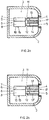
- An alternative, second embodiment of a hearing device 1 is illustrated schematically in Fig. 2a ).
- the receiver 6 is arranged within the cavity 3 as a separate module or unit with a casing 10.
- a first sound port 11 in the casing 10 of the receiver 6 providing access to the front chamber 7 of the receiver 6 is connected with the first sound opening 4 of the cavity 3 via a first sound tube 13.
- a second sound port 12 in the casing 10 of the receiver 6 providing access to the back chamber 8 of the receiver 6 is connected with the second sound opening 5 of the cavity 3 via a second sound tube 14.
- the length l 2 and inner diameter d 2 (cross-section) of the second sound tube 14 also influence the low frequency response of the hearing device 1 (as does also the compliance of the back volume), and are preferably appropriately configured to optimally adapt the acoustical characteristics of the hearing device 1, especially the resonance frequency of the receiver, to the specific needs of the user.
- the second sound tube 14 for example has an inner diameter d 2 in the range from 0.8 mm to 2 mm and a length l 2 of 12 mm.
- the first and second sound openings 4 and 5 are for instance covered by a wax protection element 17 (also referred to as wax guard) in order to prevent sweat and dirt such as ear wax from entering into the first and second sound tubes 13 and 14, thus avoiding them getting clogged.
- a third sound port 15 can be provided in the casing 10 of the receiver 6 providing further access to the back chamber 8 of the receiver 6.
- the cavity 3 acts as an extension of the back chamber 8, thus substantially increasing the overall back volume of the receiver 6. This also influences the low frequency response of the hearing device 1, so that by appropriately configuring the size of the cavity 3 the acoustical characteristics of the hearing device 1 can be optimally adapted to the needs of the user.
- Fig. 2b illustrates a variant of the embodiment shown in Fig. 2a ) where a joint or combined "double tube" 13' is utilised instead of separate first and second sound tubes 13 and 14.
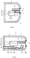
- FIG. 3 Another alternative, third embodiment of a hearing device 1 is illustrated schematically in Fig. 3 .
- the second sound port 12 included in the second embodiment is omitted, but instead the third sound port 15 is now mandatory.
- a third sound tube 16 is connected to the second sound opening 5 of the cavity 3, which acts as an extension of the back chamber 8 of the receiver 6, thus enlarging the overall back volume of the receiver. Sound then exits from the cavity 3 through this third sound tube 16, which functions as a low pass filter (together with the back volume compliance which act as a high pass).
- the third sound tube 16 too influences the low frequency response of the hearing device 1, so that by appropriately configuring the length l 3 and inner diameter d 3 (cross-section) of the third sound tube 16 the acoustical characteristics of the hearing device 1 can be optimally adapted to the needs of the user.
- an acoustic filter element can be arranged at either end of the third sound tube 16 in order to further influence the frequency response of the hearing device 1.
- a solution is also possible employing an extended double tube or two extended separate tubes.
- a hearing device 1 according to the present invention is illustrated schematically in Fig. 4 .
- the third sound tube 16 of the third embodiment is replaced with a feed into a venting canal 18, the proximal end 19 of the venting canal 18 forming the second sound opening 5 of the cavity 3.
- the distal end 19' of the venting canal 18 for instance is located at a face plate 22 of the hearing device 1 (cf. Fig. 1 ).
- the invention also requires that the casing 10 of the receiver 6 features a third sound port 15 providing access to the back chamber 8.
- the cavity 3 also acts as an extension of the back chamber 8, thus enlarging the overall back volume of the receiver 6.
- the venting canal 18 allows sound from the cavity 3 to exit to the exterior of the shell 2 through the proximal end 19, i.e.
- the inner diameter d v of the venting canal 18 influences the low frequency response of the hearing device 1, so that the acoustical characteristics of the hearing device 1 can be optimally adapted to the needs of the user by appropriately configuring the inner diameter d v (cross-section) of the venting canal 18.
- an acoustic filter 20 can be arranged at the feed into the venting canal 18 in order to further influence the low frequency response of the hearing device 1.
- a tube should be arranged at the feed into the venting canal 18 in order to avoid short-circuiting the back volume.
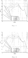
- Fig. 5 show plots of the amplitude response of a conventional hearing device and three hearing devices according to the present invention, all without a venting canal, in order to demonstrate the improvements achievable by hearing devices according to the present invention.
- the same receiver model i.e. a Sonion 31A015
- the first trace i) was derived using a conventional hearing device without an extended back volume.
- the second trace ii) was derived using a conventional hearing device employing an extended back volume.
- the low frequency response of the hearing devices according to the present invention are boosted considerably compared to the conventional hearing device, whereby the amplitude response then drops of with an additional 20 dB/decade below the boosted frequency range.
- Fig. 6 show plots of the amplitude response of two conventional hearing devices and three more hearing devices according to the present invention, all with a venting canal, in order to further demonstrate the improvements achievable by hearing devices according to the present invention.
- the sixth trace vi) was derived using a conventional hearing device with a venting canal having a diameter of 1 mm.
- the seventh trace vii) was derived using a conventional hearing device with a venting canal having a diameter of 1 mm and employing an extended back volume.
- the low frequency response of the hearing devices according to the present invention is boosted considerably compared to the conventional hearing devices, whereby the low frequencies are boosted additionally by the venting canal in these examples.
- a hearing device with an open fitting can be employed together with the present invention, where in the latter case the in-ear part of the hearing device does not seal off the ear canal but allows direct sound from outside the ear to bypass the in-ear part of the hearing device and reach the user's ear drum.
- Such "open fit" hearing devices exhibit no or at least a strongly reduced occlusion effect, since low frequency sound can pass freely in and out of the ear canal when the hearing device is being worn.
- a further aspect of the present invention pertains to a method for manufacturing the hearing device according to the present invention, whereby especially the shell 2, the second sound tube 14 and the volume of the cavity 3 acting as an extension of the back chamber 8 as well as the venting canal 18 are dimensioned by means of a rapid shell modelling (RSM) software in order to optimise the overall frequency response of the hearing device 1 individually to the needs of the user, e.g. dependent on the hearing loss of the user.
- RSM rapid shell modelling
- a rubber tube could be taken and cut to the required dimensions.
Landscapes
- Engineering & Computer Science (AREA)
- Health & Medical Sciences (AREA)
- General Health & Medical Sciences (AREA)
- Neurosurgery (AREA)
- Otolaryngology (AREA)
- Physics & Mathematics (AREA)
- Acoustics & Sound (AREA)
- Signal Processing (AREA)
- Manufacturing & Machinery (AREA)
- Obtaining Desirable Characteristics In Audible-Bandwidth Transducers (AREA)
- Headphones And Earphones (AREA)
- Soundproofing, Sound Blocking, And Sound Damping (AREA)
Claims (10)
- Hörgerät (1) zum wenigstens teilweisen Tragen innerhalb eines Gehörgangs, umfassend eine Schale (2), die einen Hohlraum (3) mit einer ersten Schallöffnung (4) und einer zweiten Schallöffnung umschließt, und aufweisend einen Hörer (6) innerhalb des Hohlraums (3), wobei der Hörer (6) durch eine Membran (9) in eine vordere Kammer (7) und eine hintere Kammer (8) unterteilt ist, wobei der Hörer (6) Folgendes umfasst: ein Gehäuse (10) mit einem ersten Schallanschluss (11), der einen Zugang zu der vorderen Kammer (7) bereitstellt, und einem dritten Schallanschluss (15), der einen Zugang zu der hinteren Kammer (8) bereitstellt, und wobei die vordere Kammer (7) über die erste Schallöffnung (4), die durch ein erstes Schallrohr (13) mit dem ersten Schallanschluss (11) verbunden ist, mit dem Äußeren der Schale (2) in akustischer Verbindung steht, dadurch gekennzeichnet, dass die hintere Kammer (8) über den dritten Schallanschluss (15) in akustischer Verbindung mit dem Hohlraum (3) steht, wobei der Hohlraum (3) eine Erweiterung der hinteren Kammer (8) bildet, und wobei der Hohlraum (3) über einen Kanal (18), der einstückig mit der Schale (2) gebildet ist, in akustischer Verbindung mit dem Äußeren der Schale (2) steht, wobei ein erstes Ende (19) des Kanals (18) die zweite Schallöffnung bildet, und ein zweites Ende des Kanals (18) eine weitere Schallöffnung (19') zum Äußeren der Schale (2) bildet, und wobei der Kanal (18) als Belüftungskanal (18) aufgebaut und ausgebildet ist, der eine Belüftung sowie einen Druckausgleich des inneren Abschnitts des Gehörgangs nach außerhalb des Ohrs bereitstellt, wenn das Hörgerät (1) getragen wird.
- Hörgerät (1) nach Anspruch 1, wobei das Gehäuse (10) einen zweiten Schallanschluss (12) aufweist, der einen weiteren Zugang zu der hinteren Kammer (8) bereitstellt, und wobei der zweite Schallanschluss (12) durch ein zweites Schallrohr (14) mit einer anderen zweiten Schallöffnung (5) verbunden ist.
- Hörgerät (1) nach Anspruch 1, wobei der Hohlraum (3) über ein drittes Schallrohr (16) in einer weiteren akustischen Verbindung mit dem Äußeren der Schale (2) steht, wobei ein Ende des dritten Schallrohrs (16) mit einer anderen zweiten Schallöffnung verbunden ist, und wobei sich ein anderes Ende des dritten Schallrohrs (16) innerhalb des Hohlraums (3) befindet.
- Hörgerät (1) nach Anspruch 2 oder 3, wobei die erste Schallöffnung (4) und die andere zweite Schallöffnung (5) durch ein Cerumenschutzelement (17) bedeckt sind, wobei zum Beispiel die erste Schallöffnung (4) und die andere zweite Schallöffnung (5) gemeinsam durch das Cerumenschutzelement (17) bedeckt sind, oder wobei alternativ, jeweils separat, die erste Schallöffnung (4) durch ein erstes Cerumenschutzelement bedeckt ist und die andere zweite Schallöffnung (5) durch einen zweiten Cerumenschutz bedeckt ist.
- Hörgerät (1) nach Anspruch 1, wobei ein akustischer Filter (20) am ersten Ende (19) des Kanals (18) angeordnet ist.
- Hörgerät (1) nach einem der vorhergehenden Ansprüche, wobei das Hörgerät (1) ein Im-Ohr-, Im-Gehörgang- oder Komplett-im-Gehörgang-Hörgerät oder ein mehrteiliges Hörgerät ist, wobei das Letztere einen außerhalb des Gehörgangs befindlichen Teil und einen im Ohr, im Gehörgang oder vollständig im Gehörgang befindlichen Teil umfasst, der den Hörer (6) umfasst.
- Mehrteiliges Hörgerät nach Anspruch 6, das dafür eingerichtet ist, eine offene Anpassung bereitzustellen.
- Verfahren zur Herstellung eines Hörgeräts (1) nach Anspruch 1, umfassend die folgenden Schritte:- Messen wenigstens eines Abschnitts einer inneren Form eines Gehörgangs eines Benutzers des Hörgeräts (1);- Erzeugen eines dreidimensionalen Computermodells von:∘ einer Schale (2), sodass die Schale (2) eine äußere Oberfläche aufweist, die individuell entsprechend der gemessenen inneren Form eines Teilstücks des Gehörgangs des Benutzers geformt ist;∘ einem Hohlraum (3) mit einer ersten Schallöffnung (4) und einer zweiten Schallöffnung, wobei der Hohlraum (3) innerhalb der Schale (2) eingeschlossen ist; und∘ einem Hörer (6) innerhalb des Hohlraums (3), wobei der Hörer (6) durch eine Membran (9) in eine vordere Kammer (7) und eine hintere Kammer (8) unterteilt ist, wobei der Hörer (6) ein Gehäuse (10) mit einem ersten Schallanschluss (11), der einen Zugang zu der vorderen Kammer (7) bereitstellt, und einem dritten Schallanschluss (15), der einen Zugang zu der hinteren Kammer (8) bereitstellt, umfasst,wobei• die vordere Kammer (7) über die erste Schallöffnung (4), die durch ein erstes Schallrohr (13) mit dem ersten Schallanschluss (11) verbunden ist, mit dem Äußeren der Schale (2) in akustischer Verbindung steht,• die hintere Kammer (8) über den dritten Schallanschluss (15) in akustischer Verbindung mit dem Hohlraum (3) steht, wobei der Hohlraum (3) eine Erweiterung der hinteren Kammer (8) bildet, und• der Hohlraum (3) über einen Kanal (18), der einstückig mit der Schale (2) gebildet ist, in akustischer Verbindung mit dem Äußeren der Schale (2) steht, wobei ein erstes Ende (19) des Kanals (18) die zweite Schallöffnung bildet und ein zweites Ende des Kanals (18) eine weitere Schallöffnung (19') zum Äußeren der Schale (2) bildet; und- Berechnen eines Frequenzgangs des Hörgeräts (1) basierend auf dem erzeugten dreidimensionalen Computermodell und auf der gemessenen inneren Form des Gehörgangs des Benutzers;- Abändern des dreidimensionalen Computermodells, wenn der berechnete Frequenzgang von einem gewünschten Frequenzgang abweicht, indem wenigstens eines von der Form, dem Querschnitt, der Länge, dem Innendurchmesser und der Lage wenigstens eines der folgenden Elemente a) bis d) abgeändert wird:a) des dritten Schallanschlusses (15);b) des Kanals (18);c) der zweiten Schallöffnung;d) der weiteren Schallöffnung (19').
- Verfahren nach Anspruch 8, wobei der Schritt des Berechnens ein Restvolumen des Gehörgangs berücksichtigt, das zwischen der Schale (2) des Hörgeräts (1) und einem Trommelfell des Benutzers verbleibt, wenn die Schale (2) in den Gehörgang des Benutzers eingefügt ist.
- Verfahren nach Anspruch 8 oder 9, wobei die Schritte des Berechnens und Abänderns wiederholt werden, bis der berechnete Frequenzgang mit dem gewünschten Frequenzgang übereinstimmt.
Applications Claiming Priority (1)
| Application Number | Priority Date | Filing Date | Title |
|---|---|---|---|
| PCT/EP2013/065430 WO2015010716A1 (en) | 2013-07-22 | 2013-07-22 | Hearing device with improved low frequency response and method for manufacturing such a hearing device |
Publications (2)
| Publication Number | Publication Date |
|---|---|
| EP3025511A1 EP3025511A1 (de) | 2016-06-01 |
| EP3025511B1 true EP3025511B1 (de) | 2019-12-25 |
Family
ID=48808365
Family Applications (1)
| Application Number | Title | Priority Date | Filing Date |
|---|---|---|---|
| EP13739445.8A Active EP3025511B1 (de) | 2013-07-22 | 2013-07-22 | Hörgerät mit verbessertem niedrigfrequenzgang und verfahren zur herstellung solch eines hörgeräts |
Country Status (5)
| Country | Link |
|---|---|
| US (1) | US9668067B2 (de) |
| EP (1) | EP3025511B1 (de) |
| CN (1) | CN105556989A (de) |
| DK (1) | DK3025511T3 (de) |
| WO (1) | WO2015010716A1 (de) |
Families Citing this family (7)
| Publication number | Priority date | Publication date | Assignee | Title |
|---|---|---|---|---|
| US10887706B2 (en) | 2015-06-29 | 2021-01-05 | Hear-Wear Technologies LLC | Transducer modules for auditory communication devices and auditory communication devices |
| US9949008B2 (en) * | 2015-08-29 | 2018-04-17 | Bragi GmbH | Reproduction of ambient environmental sound for acoustic transparency of ear canal device system and method |
| DE102016202658A1 (de) * | 2016-02-22 | 2017-08-24 | Sivantos Pte. Ltd. | Lautsprechermodul für ein Hörgerät und Hörgerät |
| JP7163194B2 (ja) | 2016-06-22 | 2022-10-31 | ドルビー ラボラトリーズ ライセンシング コーポレイション | ヘッドフォンおよびヘッドフォン・システム |
| EP3586522B1 (de) * | 2017-02-23 | 2023-01-18 | Sonova AG | Verfahren zur herstellung eines hörgerätegehäuses |
| DE102017114008A1 (de) * | 2017-06-23 | 2018-12-27 | USound GmbH | In-Ohr Hörer |
| EP4576832A3 (de) | 2022-08-22 | 2025-09-24 | Sonova AG | Schutzelement für einen elektroakustischen wandler eines hörgerätes oder für einen schallschlauch in einem hörgerät |
Citations (1)
| Publication number | Priority date | Publication date | Assignee | Title |
|---|---|---|---|---|
| EP1629808A1 (de) * | 2004-08-25 | 2006-03-01 | Phonak Ag | Ohrstöpsel und Verfahren zu dessen Herstellung |
Family Cites Families (11)
| Publication number | Priority date | Publication date | Assignee | Title |
|---|---|---|---|---|
| US5068901A (en) * | 1990-05-01 | 1991-11-26 | Knowles Electronics, Inc. | Dual outlet passage hearing aid transducer |
| US5220612A (en) | 1991-12-20 | 1993-06-15 | Tibbetts Industries, Inc. | Non-occludable transducers for in-the-ear applications |
| EP0716800A1 (de) * | 1993-09-01 | 1996-06-19 | Knowles Electronics, Inc. | Empfänger für ein hörhilfegerät |
| NL1004877C2 (nl) | 1996-12-23 | 1998-08-03 | Microtronic Nederland Bv | Elektroakoestische transducent. |
| US5960093A (en) | 1998-03-30 | 1999-09-28 | Knowles Electronics, Inc. | Miniature transducer |
| US6879696B1 (en) | 2000-06-06 | 2005-04-12 | Phonak Ag | In-ear hearing aid and method for its manufacture |
| US7181035B2 (en) | 2000-11-22 | 2007-02-20 | Sonion Nederland B.V. | Acoustical receiver housing for hearing aids |
| US20020196954A1 (en) * | 2001-06-22 | 2002-12-26 | Marxen Christopher J. | Modeling and fabrication of three-dimensional irregular surfaces for hearing instruments |
| DE102006007032A1 (de) * | 2006-02-15 | 2007-08-16 | Accusta Gmbh | Verfahren zur Herstellung eines Ohreinsatzes, Ohreinsatzanordnung und Verwendung einer Ohreinsatzanordnung |
| US20090296971A1 (en) * | 2008-05-29 | 2009-12-03 | Siemens Hearing Instruments, Inc. | Hearing Instrument Receiver With Improved Low-Frequency Efficiency |
| DE102008038213B8 (de) | 2008-08-18 | 2010-02-11 | Siemens Medical Instruments Pte. Ltd. | Hörhilfegerät mit einer Wandlerschutzeinrichtung |
-
2013
- 2013-07-22 CN CN201380079732.8A patent/CN105556989A/zh active Pending
- 2013-07-22 WO PCT/EP2013/065430 patent/WO2015010716A1/en not_active Ceased
- 2013-07-22 US US14/906,610 patent/US9668067B2/en not_active Expired - Fee Related
- 2013-07-22 EP EP13739445.8A patent/EP3025511B1/de active Active
- 2013-07-22 DK DK13739445.8T patent/DK3025511T3/da active
Patent Citations (1)
| Publication number | Priority date | Publication date | Assignee | Title |
|---|---|---|---|---|
| EP1629808A1 (de) * | 2004-08-25 | 2006-03-01 | Phonak Ag | Ohrstöpsel und Verfahren zu dessen Herstellung |
Also Published As
| Publication number | Publication date |
|---|---|
| WO2015010716A1 (en) | 2015-01-29 |
| CN105556989A (zh) | 2016-05-04 |
| EP3025511A1 (de) | 2016-06-01 |
| US9668067B2 (en) | 2017-05-30 |
| DK3025511T3 (da) | 2020-03-23 |
| US20160157027A1 (en) | 2016-06-02 |
Similar Documents
| Publication | Publication Date | Title |
|---|---|---|
| US11234085B2 (en) | Earpieces and related articles and devices | |
| EP3025511B1 (de) | Hörgerät mit verbessertem niedrigfrequenzgang und verfahren zur herstellung solch eines hörgeräts | |
| EP3422734B1 (de) | Geflanschter ohrhörer und hörgerät damit | |
| EP2671391B1 (de) | Hörgerät mit einem wandlermodul und herstellungsverfahren für das wandlermodul | |
| EP1871141B1 (de) | Hörgerät mit zwei Empfängern, von denen jeder einen unterschiedlichen Frequenzbereich verstärkt | |
| CN101455092B (zh) | 个人收听设备 | |
| CN109996138A (zh) | 具有声阀的音频装置 | |
| EP1681904B1 (de) | Hinter-dem-Ohr-Hörgerät | |
| US20040165742A1 (en) | Canal hearing device with tubular insert | |
| EP2601795B1 (de) | Lautsprechersystem für ein hörgerät | |
| EP4044623A1 (de) | Hörgerät mit einer entlüftung und einem akustischen ventil | |
| WO2004010734A1 (en) | Canal hearing device with tubular insert | |
| WO2014177214A1 (en) | Hearing instrument comprising an ear canal microphone with active control loop | |
| EP3706440A1 (de) | Hörgerät mit entlüftung | |
| CN110915229B (zh) | 耳塞式接收器 | |
| US20220046362A1 (en) | Hearing device for occlusion reduction and components thereof | |
| EP3435688A1 (de) | Im ohr tragbares hörgerät mit unverdeckten elektronischen bauteilen | |
| EP4615006A1 (de) | Schwingungsisolationsaufhängung für ohrtragbare audiokomponenten | |
| EP4564846A1 (de) | Empfängeranordnung mit hinterem akustischem durchgang für eine ohrgetragene vorrichtung | |
| EP4576818A1 (de) | Mechanisches element zur schallübertragung eines hörgeräts | |
| EP4231662A1 (de) | Hörgerät mit aktiver geräuschkontrolle | |
| EP4513899A1 (de) | Ohrglocke für ein hörgerät | |
| US20250287162A1 (en) | Hearing device comprising a mechanical element for sound transmission | |
| EP4440143A1 (de) | Hörgerät | |
| WO2009100559A2 (en) | Hearing instrument |
Legal Events
| Date | Code | Title | Description |
|---|---|---|---|
| PUAI | Public reference made under article 153(3) epc to a published international application that has entered the european phase |
Free format text: ORIGINAL CODE: 0009012 |
|
| 17P | Request for examination filed |
Effective date: 20160211 |
|
| AK | Designated contracting states |
Kind code of ref document: A1 Designated state(s): AL AT BE BG CH CY CZ DE DK EE ES FI FR GB GR HR HU IE IS IT LI LT LU LV MC MK MT NL NO PL PT RO RS SE SI SK SM TR |
|
| AX | Request for extension of the european patent |
Extension state: BA ME |
|
| DAX | Request for extension of the european patent (deleted) | ||
| STAA | Information on the status of an ep patent application or granted ep patent |
Free format text: STATUS: EXAMINATION IS IN PROGRESS |
|
| 17Q | First examination report despatched |
Effective date: 20180403 |
|
| GRAP | Despatch of communication of intention to grant a patent |
Free format text: ORIGINAL CODE: EPIDOSNIGR1 |
|
| STAA | Information on the status of an ep patent application or granted ep patent |
Free format text: STATUS: GRANT OF PATENT IS INTENDED |
|
| INTG | Intention to grant announced |
Effective date: 20190528 |
|
| GRAS | Grant fee paid |
Free format text: ORIGINAL CODE: EPIDOSNIGR3 |
|
| GRAJ | Information related to disapproval of communication of intention to grant by the applicant or resumption of examination proceedings by the epo deleted |
Free format text: ORIGINAL CODE: EPIDOSDIGR1 |
|
| GRAL | Information related to payment of fee for publishing/printing deleted |
Free format text: ORIGINAL CODE: EPIDOSDIGR3 |
|
| STAA | Information on the status of an ep patent application or granted ep patent |
Free format text: STATUS: EXAMINATION IS IN PROGRESS |
|
| GRAP | Despatch of communication of intention to grant a patent |
Free format text: ORIGINAL CODE: EPIDOSNIGR1 |
|
| STAA | Information on the status of an ep patent application or granted ep patent |
Free format text: STATUS: GRANT OF PATENT IS INTENDED |
|
| INTC | Intention to grant announced (deleted) | ||
| GRAA | (expected) grant |
Free format text: ORIGINAL CODE: 0009210 |
|
| STAA | Information on the status of an ep patent application or granted ep patent |
Free format text: STATUS: THE PATENT HAS BEEN GRANTED |
|
| INTG | Intention to grant announced |
Effective date: 20191112 |
|
| AK | Designated contracting states |
Kind code of ref document: B1 Designated state(s): AL AT BE BG CH CY CZ DE DK EE ES FI FR GB GR HR HU IE IS IT LI LT LU LV MC MK MT NL NO PL PT RO RS SE SI SK SM TR |
|
| REG | Reference to a national code |
Ref country code: GB Ref legal event code: FG4D |
|
| REG | Reference to a national code |
Ref country code: CH Ref legal event code: EP |
|
| REG | Reference to a national code |
Ref country code: DE Ref legal event code: R096 Ref document number: 602013064346 Country of ref document: DE |
|
| REG | Reference to a national code |
Ref country code: AT Ref legal event code: REF Ref document number: 1218478 Country of ref document: AT Kind code of ref document: T Effective date: 20200115 |
|
| REG | Reference to a national code |
Ref country code: IE Ref legal event code: FG4D |
|
| REG | Reference to a national code |
Ref country code: DK Ref legal event code: T3 Effective date: 20200322 |
|
| REG | Reference to a national code |
Ref country code: NL Ref legal event code: MP Effective date: 20191225 |
|
| PG25 | Lapsed in a contracting state [announced via postgrant information from national office to epo] |
Ref country code: SE Free format text: LAPSE BECAUSE OF FAILURE TO SUBMIT A TRANSLATION OF THE DESCRIPTION OR TO PAY THE FEE WITHIN THE PRESCRIBED TIME-LIMIT Effective date: 20191225 Ref country code: LV Free format text: LAPSE BECAUSE OF FAILURE TO SUBMIT A TRANSLATION OF THE DESCRIPTION OR TO PAY THE FEE WITHIN THE PRESCRIBED TIME-LIMIT Effective date: 20191225 Ref country code: NO Free format text: LAPSE BECAUSE OF FAILURE TO SUBMIT A TRANSLATION OF THE DESCRIPTION OR TO PAY THE FEE WITHIN THE PRESCRIBED TIME-LIMIT Effective date: 20200325 Ref country code: GR Free format text: LAPSE BECAUSE OF FAILURE TO SUBMIT A TRANSLATION OF THE DESCRIPTION OR TO PAY THE FEE WITHIN THE PRESCRIBED TIME-LIMIT Effective date: 20200326 Ref country code: LT Free format text: LAPSE BECAUSE OF FAILURE TO SUBMIT A TRANSLATION OF THE DESCRIPTION OR TO PAY THE FEE WITHIN THE PRESCRIBED TIME-LIMIT Effective date: 20191225 Ref country code: BG Free format text: LAPSE BECAUSE OF FAILURE TO SUBMIT A TRANSLATION OF THE DESCRIPTION OR TO PAY THE FEE WITHIN THE PRESCRIBED TIME-LIMIT Effective date: 20200325 Ref country code: FI Free format text: LAPSE BECAUSE OF FAILURE TO SUBMIT A TRANSLATION OF THE DESCRIPTION OR TO PAY THE FEE WITHIN THE PRESCRIBED TIME-LIMIT Effective date: 20191225 |
|
| REG | Reference to a national code |
Ref country code: LT Ref legal event code: MG4D |
|
| PG25 | Lapsed in a contracting state [announced via postgrant information from national office to epo] |
Ref country code: RS Free format text: LAPSE BECAUSE OF FAILURE TO SUBMIT A TRANSLATION OF THE DESCRIPTION OR TO PAY THE FEE WITHIN THE PRESCRIBED TIME-LIMIT Effective date: 20191225 Ref country code: HR Free format text: LAPSE BECAUSE OF FAILURE TO SUBMIT A TRANSLATION OF THE DESCRIPTION OR TO PAY THE FEE WITHIN THE PRESCRIBED TIME-LIMIT Effective date: 20191225 |
|
| PG25 | Lapsed in a contracting state [announced via postgrant information from national office to epo] |
Ref country code: AL Free format text: LAPSE BECAUSE OF FAILURE TO SUBMIT A TRANSLATION OF THE DESCRIPTION OR TO PAY THE FEE WITHIN THE PRESCRIBED TIME-LIMIT Effective date: 20191225 |
|
| PG25 | Lapsed in a contracting state [announced via postgrant information from national office to epo] |
Ref country code: EE Free format text: LAPSE BECAUSE OF FAILURE TO SUBMIT A TRANSLATION OF THE DESCRIPTION OR TO PAY THE FEE WITHIN THE PRESCRIBED TIME-LIMIT Effective date: 20191225 Ref country code: RO Free format text: LAPSE BECAUSE OF FAILURE TO SUBMIT A TRANSLATION OF THE DESCRIPTION OR TO PAY THE FEE WITHIN THE PRESCRIBED TIME-LIMIT Effective date: 20191225 Ref country code: NL Free format text: LAPSE BECAUSE OF FAILURE TO SUBMIT A TRANSLATION OF THE DESCRIPTION OR TO PAY THE FEE WITHIN THE PRESCRIBED TIME-LIMIT Effective date: 20191225 Ref country code: CZ Free format text: LAPSE BECAUSE OF FAILURE TO SUBMIT A TRANSLATION OF THE DESCRIPTION OR TO PAY THE FEE WITHIN THE PRESCRIBED TIME-LIMIT Effective date: 20191225 Ref country code: PT Free format text: LAPSE BECAUSE OF FAILURE TO SUBMIT A TRANSLATION OF THE DESCRIPTION OR TO PAY THE FEE WITHIN THE PRESCRIBED TIME-LIMIT Effective date: 20200520 |
|
| PG25 | Lapsed in a contracting state [announced via postgrant information from national office to epo] |
Ref country code: IS Free format text: LAPSE BECAUSE OF FAILURE TO SUBMIT A TRANSLATION OF THE DESCRIPTION OR TO PAY THE FEE WITHIN THE PRESCRIBED TIME-LIMIT Effective date: 20200425 Ref country code: SK Free format text: LAPSE BECAUSE OF FAILURE TO SUBMIT A TRANSLATION OF THE DESCRIPTION OR TO PAY THE FEE WITHIN THE PRESCRIBED TIME-LIMIT Effective date: 20191225 Ref country code: SM Free format text: LAPSE BECAUSE OF FAILURE TO SUBMIT A TRANSLATION OF THE DESCRIPTION OR TO PAY THE FEE WITHIN THE PRESCRIBED TIME-LIMIT Effective date: 20191225 |
|
| REG | Reference to a national code |
Ref country code: DE Ref legal event code: R097 Ref document number: 602013064346 Country of ref document: DE |
|
| PG25 | Lapsed in a contracting state [announced via postgrant information from national office to epo] |
Ref country code: ES Free format text: LAPSE BECAUSE OF FAILURE TO SUBMIT A TRANSLATION OF THE DESCRIPTION OR TO PAY THE FEE WITHIN THE PRESCRIBED TIME-LIMIT Effective date: 20191225 |
|
| PLBE | No opposition filed within time limit |
Free format text: ORIGINAL CODE: 0009261 |
|
| STAA | Information on the status of an ep patent application or granted ep patent |
Free format text: STATUS: NO OPPOSITION FILED WITHIN TIME LIMIT |
|
| REG | Reference to a national code |
Ref country code: AT Ref legal event code: MK05 Ref document number: 1218478 Country of ref document: AT Kind code of ref document: T Effective date: 20191225 |
|
| PG25 | Lapsed in a contracting state [announced via postgrant information from national office to epo] |
Ref country code: SI Free format text: LAPSE BECAUSE OF FAILURE TO SUBMIT A TRANSLATION OF THE DESCRIPTION OR TO PAY THE FEE WITHIN THE PRESCRIBED TIME-LIMIT Effective date: 20191225 |
|
| 26N | No opposition filed |
Effective date: 20200928 |
|
| PG25 | Lapsed in a contracting state [announced via postgrant information from national office to epo] |
Ref country code: IT Free format text: LAPSE BECAUSE OF FAILURE TO SUBMIT A TRANSLATION OF THE DESCRIPTION OR TO PAY THE FEE WITHIN THE PRESCRIBED TIME-LIMIT Effective date: 20191225 Ref country code: AT Free format text: LAPSE BECAUSE OF FAILURE TO SUBMIT A TRANSLATION OF THE DESCRIPTION OR TO PAY THE FEE WITHIN THE PRESCRIBED TIME-LIMIT Effective date: 20191225 |
|
| PG25 | Lapsed in a contracting state [announced via postgrant information from national office to epo] |
Ref country code: PL Free format text: LAPSE BECAUSE OF FAILURE TO SUBMIT A TRANSLATION OF THE DESCRIPTION OR TO PAY THE FEE WITHIN THE PRESCRIBED TIME-LIMIT Effective date: 20191225 Ref country code: MC Free format text: LAPSE BECAUSE OF FAILURE TO SUBMIT A TRANSLATION OF THE DESCRIPTION OR TO PAY THE FEE WITHIN THE PRESCRIBED TIME-LIMIT Effective date: 20191225 |
|
| REG | Reference to a national code |
Ref country code: CH Ref legal event code: PL |
|
| REG | Reference to a national code |
Ref country code: BE Ref legal event code: MM Effective date: 20200731 |
|
| PG25 | Lapsed in a contracting state [announced via postgrant information from national office to epo] |
Ref country code: LU Free format text: LAPSE BECAUSE OF NON-PAYMENT OF DUE FEES Effective date: 20200722 Ref country code: LI Free format text: LAPSE BECAUSE OF NON-PAYMENT OF DUE FEES Effective date: 20200731 Ref country code: CH Free format text: LAPSE BECAUSE OF NON-PAYMENT OF DUE FEES Effective date: 20200731 |
|
| PG25 | Lapsed in a contracting state [announced via postgrant information from national office to epo] |
Ref country code: BE Free format text: LAPSE BECAUSE OF NON-PAYMENT OF DUE FEES Effective date: 20200731 |
|
| PG25 | Lapsed in a contracting state [announced via postgrant information from national office to epo] |
Ref country code: IE Free format text: LAPSE BECAUSE OF NON-PAYMENT OF DUE FEES Effective date: 20200722 |
|
| PGFP | Annual fee paid to national office [announced via postgrant information from national office to epo] |
Ref country code: FR Payment date: 20210726 Year of fee payment: 9 |
|
| PGFP | Annual fee paid to national office [announced via postgrant information from national office to epo] |
Ref country code: DK Payment date: 20210728 Year of fee payment: 9 Ref country code: GB Payment date: 20210727 Year of fee payment: 9 Ref country code: DE Payment date: 20210728 Year of fee payment: 9 |
|
| PG25 | Lapsed in a contracting state [announced via postgrant information from national office to epo] |
Ref country code: TR Free format text: LAPSE BECAUSE OF FAILURE TO SUBMIT A TRANSLATION OF THE DESCRIPTION OR TO PAY THE FEE WITHIN THE PRESCRIBED TIME-LIMIT Effective date: 20191225 Ref country code: MT Free format text: LAPSE BECAUSE OF FAILURE TO SUBMIT A TRANSLATION OF THE DESCRIPTION OR TO PAY THE FEE WITHIN THE PRESCRIBED TIME-LIMIT Effective date: 20191225 Ref country code: CY Free format text: LAPSE BECAUSE OF FAILURE TO SUBMIT A TRANSLATION OF THE DESCRIPTION OR TO PAY THE FEE WITHIN THE PRESCRIBED TIME-LIMIT Effective date: 20191225 |
|
| PG25 | Lapsed in a contracting state [announced via postgrant information from national office to epo] |
Ref country code: MK Free format text: LAPSE BECAUSE OF FAILURE TO SUBMIT A TRANSLATION OF THE DESCRIPTION OR TO PAY THE FEE WITHIN THE PRESCRIBED TIME-LIMIT Effective date: 20191225 |
|
| REG | Reference to a national code |
Ref country code: DE Ref legal event code: R119 Ref document number: 602013064346 Country of ref document: DE |
|
| REG | Reference to a national code |
Ref country code: DK Ref legal event code: EBP Effective date: 20220731 |
|
| GBPC | Gb: european patent ceased through non-payment of renewal fee |
Effective date: 20220722 |
|
| PG25 | Lapsed in a contracting state [announced via postgrant information from national office to epo] |
Ref country code: FR Free format text: LAPSE BECAUSE OF NON-PAYMENT OF DUE FEES Effective date: 20220731 |
|
| PG25 | Lapsed in a contracting state [announced via postgrant information from national office to epo] |
Ref country code: GB Free format text: LAPSE BECAUSE OF NON-PAYMENT OF DUE FEES Effective date: 20220722 Ref country code: DE Free format text: LAPSE BECAUSE OF NON-PAYMENT OF DUE FEES Effective date: 20230201 |
|
| PG25 | Lapsed in a contracting state [announced via postgrant information from national office to epo] |
Ref country code: DK Free format text: LAPSE BECAUSE OF NON-PAYMENT OF DUE FEES Effective date: 20220731 |