EP3025571B1 - Épandeur centrifuge pour sel à épandre - Google Patents
Épandeur centrifuge pour sel à épandre Download PDFInfo
- Publication number
- EP3025571B1 EP3025571B1 EP15401115.9A EP15401115A EP3025571B1 EP 3025571 B1 EP3025571 B1 EP 3025571B1 EP 15401115 A EP15401115 A EP 15401115A EP 3025571 B1 EP3025571 B1 EP 3025571B1
- Authority
- EP
- European Patent Office
- Prior art keywords
- spreading
- mass flow
- characteristic curve
- parameter values
- computer
- Prior art date
- Legal status (The legal status is an assumption and is not a legal conclusion. Google has not performed a legal analysis and makes no representation as to the accuracy of the status listed.)
- Active
Links
Images

Classifications
-
- A—HUMAN NECESSITIES
- A01—AGRICULTURE; FORESTRY; ANIMAL HUSBANDRY; HUNTING; TRAPPING; FISHING
- A01C—PLANTING; SOWING; FERTILISING
- A01C17/00—Fertilisers or seeders with centrifugal wheels
- A01C17/006—Regulating or dosing devices
-
- A—HUMAN NECESSITIES
- A01—AGRICULTURE; FORESTRY; ANIMAL HUSBANDRY; HUNTING; TRAPPING; FISHING
- A01C—PLANTING; SOWING; FERTILISING
- A01C17/00—Fertilisers or seeders with centrifugal wheels
- A01C17/006—Regulating or dosing devices
- A01C17/008—Devices controlling the quantity or the distribution pattern
-
- E—FIXED CONSTRUCTIONS
- E01—CONSTRUCTION OF ROADS, RAILWAYS, OR BRIDGES
- E01C—CONSTRUCTION OF, OR SURFACES FOR, ROADS, SPORTS GROUNDS, OR THE LIKE; MACHINES OR AUXILIARY TOOLS FOR CONSTRUCTION OR REPAIR
- E01C19/00—Machines, tools or auxiliary devices for preparing or distributing paving materials, for working the placed materials, or for forming, consolidating, or finishing the paving
- E01C19/12—Machines, tools or auxiliary devices for preparing or distributing paving materials, for working the placed materials, or for forming, consolidating, or finishing the paving for distributing granular or liquid materials
- E01C19/20—Apparatus for distributing, e.g. spreading, granular or pulverulent materials, e.g. sand, gravel, salt, dry binders
- E01C19/201—Apparatus for distributing, e.g. spreading, granular or pulverulent materials, e.g. sand, gravel, salt, dry binders with driven loosening, discharging or spreading parts, e.g. power-driven, drive derived from road-wheels
- E01C19/202—Apparatus for distributing, e.g. spreading, granular or pulverulent materials, e.g. sand, gravel, salt, dry binders with driven loosening, discharging or spreading parts, e.g. power-driven, drive derived from road-wheels solely rotating, e.g. discharging and spreading drums
- E01C19/203—Centrifugal spreaders with substantially vertical axis
-
- E—FIXED CONSTRUCTIONS
- E01—CONSTRUCTION OF ROADS, RAILWAYS, OR BRIDGES
- E01C—CONSTRUCTION OF, OR SURFACES FOR, ROADS, SPORTS GROUNDS, OR THE LIKE; MACHINES OR AUXILIARY TOOLS FOR CONSTRUCTION OR REPAIR
- E01C19/00—Machines, tools or auxiliary devices for preparing or distributing paving materials, for working the placed materials, or for forming, consolidating, or finishing the paving
- E01C19/12—Machines, tools or auxiliary devices for preparing or distributing paving materials, for working the placed materials, or for forming, consolidating, or finishing the paving for distributing granular or liquid materials
- E01C19/20—Apparatus for distributing, e.g. spreading, granular or pulverulent materials, e.g. sand, gravel, salt, dry binders
- E01C2019/2055—Details not otherwise provided for
- E01C2019/2065—Sensing the quantity of the material actually being distributed
Definitions
- the invention relates to a centrifugal spreader for distributing grit according to the preamble of claim 1.
- the relationship between the drive torque and the spreading material mass flow depends on various setting parameters, such as the centrifugal discs used, the speed of the discs, the effective radius of the spreading vanes, the distance of the grit feeding area to the spreading disc rotation axis and the type and arrangement of the spreading vanes on the lens. Therefore, with the measured torque in the scattering operation alone, no statement or only an inaccurate statement about the actual mass flow can be made. The above parameters must be included in the determination.
- This object is achieved by storing in the computer a basic characteristic curve dependent on the adjustment parameters for the mass flow, that an input device for inputting parameter values into the computer by a user is provided, via which one or more of the parameter values belonging to the respective operating state are entered
- the computer calculates the operating characteristic curve with which the actual mass flow is calculated for the control, wherein according to the invention the operating characteristic curve is calculated by calculating the basic characteristic curve based on a stored calculation rule into which parameter values Enter parameters is modified and wherein the calculation rule is not exclusively empirical, but partially calculated.
- the operating characteristic may define a, in particular computational, relationship between the measured torque and the actual mass flow in the set or selected operating state.
- the adjustment parameters can be, for example, the travel speed, the grit size, the rotation speed, the type of diffuser, for example standard diffuser, boundary diffuser, etc., the moment of inertia of the diffusers, the working width, the desired amount of grit per surface. These can then be entered numerically by the user. However, it is also possible that the user input is a transcription of the operating state (for example, "border spreading disc") and that corresponding numerical values are stored in the computer, which are then the actual parameter values. For the sake of simplicity, however, the latter case is also described as "inputting parameter values", even if it is only an indirect input of numerical values.
- the calculation of the operating characteristic curve is carried out by modifying the basic characteristic curve on the basis of a stored calculation rule, into which parameter values enter as parameters.
- exactly one operating characteristic is thus determined from exactly one basic characteristic by the parameter values being used in the calculation specification, so that from an initial characteristic, any desired operating characteristic can be determined for each of a plurality of operating states.
- all operating characteristics must be determined and stored by measurements.
- only the basic characteristic and at most two, preferably exactly one, operating characteristic are stored in the computer at the same time.
- a basic characteristic curve or a formula is stored in the computer, in which various parameters are incorporated, for example the speed, the effective radius of the spreading vanes, the distance of the spreading material application area to the spreading axis and the arrangement of the spreading vanes on the lens.
- various parameters for example the speed, the effective radius of the spreading vanes, the distance of the spreading material application area to the spreading axis and the arrangement of the spreading vanes on the lens.
- the values of the setting parameters of the current operating state are used and thus obtained a new formula.
- the operator enters the blade lengths that he has set in the computer, whereby the basic characteristic is modified based on the stored calculation rule in such a way that the relationship between torque and mass flow now applies to the set blade length.
- This relationship is described by the operating characteristic, by means of which the mass flow can then be determined indirectly via the torque during operation.
- the speed of the turntable can be determined by tachometers.
- the calculation rule is not exclusively empirical, but determined in part mathematically.
- the calculation rule can in particular be obtained by combining several empirically determined calculation rules into a single calculation rule, for example by proportional multiplication.
- the calculation rule can be determined, for example, by recording the value of several parameters and applying various known mass flows to the lens and measuring the required drive torque. From the values, a first equation is derived. Thereafter, the mass flow and all but one parameter are kept at a fixed value and the drive torque is measured at different values of the one parameter. From this a second equation can be derived. This is done for all parameters. For example, the mass flow, the rotational speed and the effective radius can be varied in succession. This results in three equations. From this, a calculation rule for the mass flow in dependence on the speed, the effective radius and the drive torque can be obtained. From the equations, a general calculation rule for the mass flow as a function of the torque and the setting parameters can be determined. For example, this calculation rule can be obtained by proportional multiplication of the individual equations.
- the calculation rule can represent a continuous function, so that even for any small changes in the parameter values no abrupt change in the values of the control curve occurs. This has the advantage that small changes in the parameters to be set also lead to any small changes in the functional value, ie the output mass flow. If one were to work with individual operating characteristics or table values, the closest operating characteristic curve or the closest table value would always be used, but this is not exact when setting intermediate values.
- Adjusting the spreader to various operating conditions may include adjusting and / or varying the blade length or blade position, changing the spreading area of spreading material onto the lens, varying the rotational speed, deploying other spreading material, and / or replacing one or more spreader discs.
- the spreader may include a display device that indicates to the user which parameter values to input and which parameter values are already set.
- a warning device can be provided which issues a warning if parameter values are input which are outside a permissible range and / or if a combination of the parameter values is an inadmissible combination and / or if required parameter values are missing. Which parameter values are required and / or which parameter values and combinations are permissible can be stored on the computer. If required parameter values are not entered, alternatively or additionally a stored default value can be automatically set and the user can be given a corresponding note.
- the method for distributing grit comprises rotating at least one diffuser according to the preamble of claim 8, wherein in the computer dependent on the setting parameters base characteristic for the mass flow is stored, a user one or more belonging to the respective operating state parameter values in one Calculator enters and the computer calculates the operating characteristic curve after entering the parameter values from the basic characteristic, with which the actual mass flow is calculated for the rules, wherein the calculation of the operating characteristic is performed by the base characteristic based on a stored calculation rule, in which parameter values as parameters , is modified and according to the invention, the calculation rule is not exclusively empirically, but partially determined by calculation.
- the operating characteristic may define a relationship between the measured torque and the actual mass flow in the set operating state.
- the calculated operating characteristic can be immediately deleted after the end of the operation or stored and used for calculating the actual mass flow, until new setting parameters are entered and a new operating characteristic is calculated.
- the calculation of the operating characteristic curve takes place by modifying the basic characteristic curve on the basis of a stored calculation rule into which the parameter values are taken as parameters.
- the calculation rule is not exclusively empirical, but determined in part mathematically.
- the calculation rule can be obtained by combining several empirically determined calculation rules into a single calculation rule, for example by proportional multiplication.
- the calculation rule can represent a continuous function, so that even for arbitrary small changes of the entered parameter values no abrupt change of the values of the control curve occurs.
- Adjusting the spreader to various operating conditions may include adjusting and / or changing the blade length or blade position, changing the spreading area of spreading material onto the lens, changing the rotational speed, inserting other spreading material and / or replacing one or more spreading discs and / or throwing blades.
- the method can be carried out in particular with one of the devices described above.
- centrifugal spreader which distributes granular dry fertilizer by means of two spreading discs.
- centrifugal spreaders can also be other types of centrifugal spreaders, for example, spreaders in winter service act.
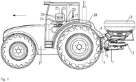
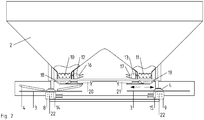
- FIGS. 1 and 2 show different views of the centrifugal spreader.
- the centrifugal spreader has the frame 1, the reservoir 2 and the lenses 3 with the throwing blades 4.
- three-point coupling elements 5 are arranged for example on the front of the frame over which the centrifugal spreader is to be arranged on a three-point hitch 6 of a tractor 7.
- other suspensions may be provided.
- drives that drive the lenses rotating for example, hydraulic motors 8 and 9 are used here.
- other drives such as electric motors or mechanical drive transmissions are also conceivable.
- the metering devices designed as cam rollers 10 and 11 are arranged. However, other metering devices may be used.
- the cam roller 10 is here driven by the hydraulic motor 12 and the cam roller 11 of the hydraulic motor 13.
- the hydraulic motors 12 and 13 can be replaced by other drives, such as electric motors.
- the hydraulic motors 8, 9, 12 and 13 can be connected via lines to the hydraulic system of the tractor.
- Electronically controllable valves 14, 15, 16 and 17 are arranged on the hydraulic motors with which the rotational speeds of the hydraulic motors can be adjusted.
- Below the metering devices 10 and 11, the discharge chutes 18 and 19 are arranged.
- the discharge chutes are to be moved here via the adjustment devices 20 and 21 designed as electric motors, so that the delivery area or the discharge area of the material dispensed by the metering devices from the storage material can be adjusted or changed to the respective spreading disk.
- the effective radius of the spreading vanes can be adjusted by the blade length is adjusted.
- a torque sensor 22 is arranged for measuring the torque of the respective drive, here for example a magnetic torque sensor.
- the torque sensor may be arranged on a drive shaft of the lenses.
- the torque sensor is indicated by dashed lines, since it is arranged in the interior of a housing of the respective drive.
- Other types and arrangements of torque sensors are also conceivable.
- FIG. 1 the computer 23 to which an input device 24 is connected in the form of a keyboard here.
- a display device 25 is connected to the computer, which displays a user interface that allows the user to enter suitable values for the parameters in corresponding fields 26 with the keyboard.
- the user can, for example, be shown which values have already been set and which values still have to be entered.
- the computer may also include a sound output that emits a warning tone when the user inputs improper values or when values are missing when the user wants to start operation.
- the control device 27 is integrated here in the computer. Alternatively, it can also be arranged outside the computer and be connected to the computer in a contactless or contact-based manner via a data connection.
- the control device is connected to the controllable valves, ie indirectly with the metering device and with the torque sensor, each via a data connection.
- the data connection is contact-based, ie with one or more cables 28, formed. However, it may also be contactless, for example as a Bluetooth connection or WLAN connection. Which type of data connection is advantageous depends inter alia on the arrangement of the control device.
- a method for distributing spreading material is described with reference to the centrifugal spreader described above, but can also be done with another centrifugal spreader.
- the basic characteristic curve is defined by a function which describes a general relationship between mass flow and torque and contains the setting parameters. To obtain the operating characteristic, the parameter values are used in this function. The insertion of the parameter values may, for example, shift, compress, stretch and / or change the slope of the base characteristic.
- an effective radius c r and a speed c n is set constant.
- various known mass flows ⁇ are delivered to the lens and the required drive torque M c r , c n measured.
- a speed c n and a mass flow c ⁇ is set constant and the drive torque M c n , c m ' determined at different radii r .
- M c n . c m ⁇ r c 6 r 2 + c 7 r + c 8th
- Equation 6 mathematically represents the basic characteristic and is stored in the computer of the centrifugal spreader.
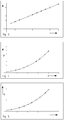
- An exemplary basic characteristic BA is in FIG. 6 shown in dashed lines. The basic characteristic depends on different operating parameters, in which values are used later. For this reason, all constants have been set to 1 for the graphical representation.
- characteristic curves have to be determined beforehand in the factory of the manufacturer, they are considerably less than in the prior art, and they are not stored as operating characteristics in the computer of the centrifugal spreader, but used only for the one-time determination of the basic characteristic and can then be discarded.
- the entered parameter values must be used for the variables (n, r).
- the blade length of the spreading discs is adjusted with a servomotor. This changes the effective radius of the spreading discs.
- the delivery area of the grit can be adjusted by adjusting the discharge chutes with the electric motors and / or changed, in which case, for example, the position of the lenses could be entered as a parameter value.
- the type of diffuser be changed, for example, by a change from a normal diffuser to a boundary lens or a diffuser with a different working and / or throw range
- the user inputs the new parameter value (s) for the set operating state, for example the new blade length, with the input device. All other fields can already be pre-filled with the previously used parameter values, for example the speed and the grit type, or with default values, or the user can reenter them.
- a warning tone sounds when an invalid value is entered, or a required value is not specified, and stops the confirmation process.
- invalid values are letters in pure number fields or numerical values that are not within a given interval. For example, it is thus possible to avoid using values which deviate by orders of magnitude from typical values and would lead to disturbances in operation.
- the entered parameter values (or, if a description is entered in the field, the Description of associated numerical values) for the variables (eg r) in equation 6. That is, the basic characteristic is modified so as to obtain the operation characteristic BE1 for the set operation state.
- Each measured torque value can now be assigned exactly one mass flow value by the operating characteristic.
- the operating characteristic is steady in this case.
- the lenses are put into operation.
- the lenses are rotated by the respective drives at a certain speed by the valves belonging to the hydraulic motors 8 and 9 14 and 15 are adjusted accordingly, and on the rotating lenses is given through the discharge chutes, which of the rotating lenses, passed through the spreading vanes, accelerated radially outwards and so distributed.
- a drive torque is needed, which is measured with the torque sensor.
- the torque value is sent from the torque sensor to the controller.
- an actual mass flow is determined.
- the control device is then determined by a comparison, whether the actual mass flow corresponds to a desired mass flow. If this is not the case, the control device regulates the metering device such that the mass flow is corrected in the desired direction until the actual mass flow corresponds to the desired mass flow. In the above example, therefore, the valves 16 and 17 of the hydraulic motors 12 and 13 which drive the cam rollers 11 and 12 are controlled.
- the operating characteristic is used, which represents the relationship between the actual mass flow and the measured torque in the current operating state and from which a mass flow value is calculated for each torque value.
- the operating characteristic BE1 can also be stored as a setting after the operation has ended. When the operation is resumed and the operating state remains unchanged, the operating characteristic BE1 can continue to be used. If the operating state is changed, either by replacing individual parameter values in the operating characteristic BE1 or by the desired direction is corrected until the actual mass flow corresponds to the desired mass flow. In the above example, therefore, the valves 16 and 17 of the hydraulic motors 12 and 13 which drive the cam rollers 11 and 12 are controlled. For the determination of the actual mass flow from the measured torque, the operating characteristic is used, which represents the relationship between the actual mass flow and the measured torque in the current operating state and from which a mass flow value is calculated for each torque value.
- the operating characteristic BE1 can also be stored as a setting after the operation has ended. When the operation is resumed and the operating state remains unchanged, the operating characteristic BE1 can continue to be used. If the operating state is changed, either by replacing individual parameter values in the operating characteristic curve BE1 or by entering new parameter values into the basic characteristic curve BA, a new operating characteristic curve BE2, which is assigned to the new operating state, can be calculated, as in FIG FIG. 7 shown. Before or at the latest immediately after the calculation of the operating characteristic BE2, the operating characteristic BE1 is preferably cleared in order to free up memory space.
Landscapes
- Life Sciences & Earth Sciences (AREA)
- Soil Sciences (AREA)
- Environmental Sciences (AREA)
- Engineering & Computer Science (AREA)
- Architecture (AREA)
- Civil Engineering (AREA)
- Structural Engineering (AREA)
- Control Of Positive-Displacement Air Blowers (AREA)
- Application Of Or Painting With Fluid Materials (AREA)
- Fertilizing (AREA)
Claims (10)
- Epandeuse centrifuge destinée à épandre un produit d'épandage, présentant
un récipient (2) à produit d'épandage et au moins un disque d'épandage (3) doté d'aubes d'épandage (4),
un entraînement (8, 9) qui entraîne à rotation le disque d'épandage (3),
un capteur (22) de couple de rotation qui mesure le couple de rotation d'un entraînement (8, 9),
un ensemble de dosage (10) apte à être régulé par un dispositif de régulation (27) assisté par calculateur,
le dispositif de régulation (27) étant configuré de manière à comparer un écoulement massique effectif à un écoulement massique de consigne prédéterminé, l'écoulement massique effectif étant associé par une ligne caractéristique de fonctionnement (BE1, BE2) au couple de rotation qui a été mesuré,
un ensemble de réglage qui règle différents états de fonctionnement de l'épandeuse centrifuge, par exemple la vitesse d'avancement, le type de répartition, le type de disque d'épandage, la quantité de consigne de produit d'épandage par unité de surface, la largeur de travail, le type de produit d'épandage et la vitesse de rotation, une ou plusieurs valeurs de paramètres de réglage étant associées à chacun des états de fonctionnement et
un calculateur dans lequel les valeurs des paramètres peuvent être introduites,
une ligne caractéristique de base (BA) du débit massique, qui dépend des paramètres de réglage, étant conservée dans le calculateur (23),
un ensemble d'introduction (24) étant prévu pour permettre à un utilisateur d'introduire des valeurs de paramètres dans le calculateur et permettant d'introduire une ou plusieurs des valeurs de paramètres qui font partie de chaque état de fonctionnement,
le calculateur (23) calculant après l'introduction des valeurs de paramètres et à partir de la ligne caractéristique de base (BA) la ligne caractéristique de fonctionnement (BE1, BE2) avec laquelle le débit massique effectif est calculé pour la régulation, caractérisée en ce que
le calcul de la ligne caractéristique de fonctionnement (BE1, BE2) s'effectue en modifiant la ligne caractéristique de base (BA) à l'aide d'une prescription de calcul conservée en mémoire et dans laquelle les valeurs de paramètres interviennent comme paramètres et
en ce que la prescription de calcul n'est pas déterminée uniquement empiriquement mais en partie par calcul. - Epandeuse centrifuge selon la revendication 1, dans laquelle la ligne caractéristique de fonctionnement (BE1, BE2) définit une dépendance entre le couple de rotation mesuré et le débit massique effectif dans l'état de fonctionnement qui a été établi.
- Epandeuse centrifuge selon l'une des revendications 1 ou 2, dans laquelle la prescription de calcul est obtenue en rassemblant plusieurs prescriptions de calcul définies empiriquement en une unique prescription de calcul, par exemple par multiplication fractionnelle.
- Epandeuse centrifuge selon l'une des revendications 1 à 3, dans laquelle la prescription de calcul constitue une fonction constante de sorte que même pour de quelconques petites modifications des valeurs de paramètre, aucune modification brusque des valeurs de la courbe de régulation n'ait lieu.
- Epandeuse centrifuge selon l'une des revendications 1 à 4, dans lequel le réglage de l'épandeuse centrifuge comporte l'ajustement à plusieurs états de fonctionnement différents de la longueur des aubes ou de la position des aubes, la modification de la zone d'application du produit d'épandage sur le disque d'épandage, la modification de la vitesse de rotation, l'utilisation d'un autre produit d'épandage et/ou le remplacement d'un ou plusieurs disques d'épandage (3).
- Procédé de répartition de produit d'épandage, comprenant les étapes qui consistent à :régler une épandeuse centrifuge en différents états de fonctionnement, par exemple la vitesse d'avancement, le type de répartition, le type de disque d'épandage, la quantité de consigne de produit d'épandage par unité de surface, la largeur de travail, le type de produit d'épandage et la vitesse de rotation, une ou plusieurs valeurs de paramètres de réglage étant associées à chacun des états de fonctionnement,entraîner en rotation au moins un disque d'épandage (3) présentant des aubes d'épandage (4) au moyen d'un entraînement (8, 9) et mesurer le couple de rotation de l'entraînement (8, 9) etréguler un ensemble de dosage (10) présentant un dispositif de régulation (27) assisté par calculateur, un écoulement massique d'effectif étant comparé à un écoulement massique de consigne prédéterminé en vue de la régulation, l'écoulement massique effectif étant associé par une ligne caractéristique de fonctionnement (BE1, BE2) au couple de rotation qui a été mesuré,une ligne caractéristique de base (BA) de l'écoulement massique, qui dépend des paramètres de réglage, étant conservée dans le calculateur (23),un utilisateur introduisant dans le calculateur (23) une ou plusieurs valeurs de paramètres qui appartiennent à l'état de fonctionnement particulier,après introduction de valeurs de paramètres, le calculateur (23) calculant à partir de la ligne de base (BA) la ligne caractéristique de fonctionnement (BE1, BE2) avec laquelle l'écoulement massique effectif est calculé pour la régulation,caractérisé en ce quele calcul de la ligne caractéristique de fonctionnement (BE1, BE2) s'effectue en modifiant la ligne caractéristique de base (BA) à l'aide d'une prescription de calcul conservée en mémoire et dans laquelle les valeurs de paramètres interviennent comme paramètres eten ce que la prescription de calcul n'est pas déterminée uniquement empiriquement mais en partie par calcul.
- Procédé selon la revendication 6, dans lequel la ligne caractéristique de fonctionnement (BE1, BE2) est effacée immédiatement ou conservée jusqu'à la fin du fonctionnement disque d'épandage (3) et est utilisée pour le calcul de l'écoulement massique effectif jusqu'à ce de nouveaux paramètres de réglage soient introduits et qu'une nouvelle ligne caractéristique de fonctionnement (BE1, BE2) soit calculée.
- Procédé selon les revendications 6 ou 7, dans lequel la prescription de calcul est obtenue en rassemblant plusieurs prescriptions de calcul définies empiriquement en une unique prescription de calcul, par exemple par multiplication fractionnelle.
- Procédé selon l'une des revendications 6 à 8, dans lequel la prescription de calcul constitue une fonction constante de sorte que même pour de quelconques petites modifications des valeurs de paramètre, aucune modification brusque des valeurs de la courbe de régulation n'ait lieu.
- Procédé selon l'une des revendications 6 à 9, dans lequel le réglage de l'épandeuse centrifuge comporte l'ajustement à plusieurs états de fonctionnement différents de la longueur des aubes ou de la position des aubes, la modification de la zone d'application du produit d'épandage sur le disque d'épandage, la modification de la vitesse de rotation, l'utilisation d'un autre produit d'épandage et/ou le remplacement d'un ou plusieurs disques d'épandage.
Applications Claiming Priority (1)
| Application Number | Priority Date | Filing Date | Title |
|---|---|---|---|
| DE102014117376.7A DE102014117376A1 (de) | 2014-11-27 | 2014-11-27 | Schleuderstreuer zum Verteilen von Streugut |
Publications (2)
| Publication Number | Publication Date |
|---|---|
| EP3025571A1 EP3025571A1 (fr) | 2016-06-01 |
| EP3025571B1 true EP3025571B1 (fr) | 2018-03-21 |
Family
ID=54697522
Family Applications (1)
| Application Number | Title | Priority Date | Filing Date |
|---|---|---|---|
| EP15401115.9A Active EP3025571B1 (fr) | 2014-11-27 | 2015-11-11 | Épandeur centrifuge pour sel à épandre |
Country Status (3)
| Country | Link |
|---|---|
| EP (1) | EP3025571B1 (fr) |
| DE (1) | DE102014117376A1 (fr) |
| DK (1) | DK3025571T3 (fr) |
Family Cites Families (6)
| Publication number | Priority date | Publication date | Assignee | Title |
|---|---|---|---|---|
| DE4417549C2 (de) * | 1994-05-19 | 2003-12-11 | Bosch Gmbh Robert | Anordnung zur Dosierung und Verteilung von Streugut |
| HUP0001995A3 (en) | 1997-02-21 | 2002-02-28 | Ppg Ind Ohio Inc Cleveland | Photochromic polyurethane coatings and articles having such a coating |
| DE59910376D1 (de) | 1998-06-10 | 2004-10-07 | Rauch Landmaschfab Gmbh | Schleuderstreuer |
| DE202012002455U1 (de) * | 2012-03-12 | 2013-03-13 | Rauch Landmaschinenfabrik Gmbh | Scheibenstreuer mit steuerbarem Dosierorgan und Steuergerät eines solchen Scheibenstreuers |
| DE102013002393A1 (de) * | 2013-02-13 | 2014-08-14 | Rauch Landmaschinenfabrik Gmbh | Verfahren zur Regelung des Massenstromes an Streugut bei einem Scheibenstreuer |
| DE102014102645A1 (de) * | 2014-02-28 | 2015-09-03 | Amazonen-Werke H. Dreyer Gmbh & Co. Kg | Streuvorrichtung und Verfahren zur Erfassung eines Massenstroms in einer Streuvorrichtung |
-
2014
- 2014-11-27 DE DE102014117376.7A patent/DE102014117376A1/de not_active Withdrawn
-
2015
- 2015-11-11 DK DK15401115.9T patent/DK3025571T3/en active
- 2015-11-11 EP EP15401115.9A patent/EP3025571B1/fr active Active
Non-Patent Citations (1)
| Title |
|---|
| None * |
Also Published As
| Publication number | Publication date |
|---|---|
| DK3025571T3 (en) | 2018-06-18 |
| DE102014117376A1 (de) | 2016-06-02 |
| EP3025571A1 (fr) | 2016-06-01 |
Similar Documents
| Publication | Publication Date | Title |
|---|---|---|
| EP0963690B1 (fr) | Epandeur centrifuge | |
| DE2858234C2 (fr) | ||
| EP2912934B1 (fr) | Dispositif d'épandage et procédé de détection d'un flux de matière dans un dispositif d'épandage | |
| EP0472855B1 (fr) | Méthode d'étalonnage d'un distributeur d'engrais | |
| EP3017678B1 (fr) | Procédé et dispositif de calcul de paramètres de réglage d'un épandeur d'engrais | |
| DE102014116020A1 (de) | Verfahren zur Massenstrombestimmung bei einer Verteilmaschine | |
| EP3081067B1 (fr) | Procédé de réglage du débit de matière d'épandage à partir d'un épandeur à disques, épandeur à disques et utilisation des disques répartiteurs correspondants | |
| EP3025571B1 (fr) | Épandeur centrifuge pour sel à épandre | |
| DE3642502C2 (fr) | ||
| DE19825917A1 (de) | Schleuderstreuer | |
| DE10237539B4 (de) | Schleuderdüngerstreuer | |
| EP3406126B1 (fr) | Épandeur centrifuge à réglage d'épandage amélioré | |
| EP3195713B1 (fr) | Procédé et épandeur d'engrais | |
| DE69519244T2 (de) | Streu-Verfahren, insbesondere für Samen oder Dünger | |
| EP2740342A1 (fr) | Epandeur d'engrais centrifuge | |
| DE102015210212A1 (de) | Verfahren und Vorrichtung zum Ausbringen von körnigem Gut | |
| DE102004004730A1 (de) | Verfahren zur Eichung / Kalibrierung einer elektronischen Zählvorrichtung | |
| EP3165072A1 (fr) | Épandeur centrifuge à détermination de débit massique améliorée | |
| EP2907371A1 (fr) | Dispositif d'épandage et procédé de réglage d'une distribution latérale d'un flux de matière répandu par le dispositif d'épandage | |
| EP3409094B1 (fr) | Procédé de planification et/ou de mise en oeuvre d'un processus d'apport d'engrais | |
| DE102015119079A1 (de) | Zentrifugalstreuer mit verbesserter Füllstandsbestimmung | |
| DE102015119076A1 (de) | Zentrifugalstreuer zum Ausbringen von Streugut | |
| DE102017112057B4 (de) | Zentrifugalstreuer mit Berücksichtigung von Ventilationsverlusten | |
| DE102016103920A1 (de) | Zentrifugalstreuer zum Ausbringen von Streugut | |
| DE102023115653A1 (de) | Behälter für ein landwirtschaftliches gut mit einer fördereinrichtung, landwirtschaftliches arbeitsgerät mit einem behälter und verfahren zum betrieb eines landwirtschaftlichen arbeitsgeräts |
Legal Events
| Date | Code | Title | Description |
|---|---|---|---|
| PUAI | Public reference made under article 153(3) epc to a published international application that has entered the european phase |
Free format text: ORIGINAL CODE: 0009012 |
|
| AK | Designated contracting states |
Kind code of ref document: A1 Designated state(s): AL AT BE BG CH CY CZ DE DK EE ES FI FR GB GR HR HU IE IS IT LI LT LU LV MC MK MT NL NO PL PT RO RS SE SI SK SM TR |
|
| AX | Request for extension of the european patent |
Extension state: BA ME |
|
| 17P | Request for examination filed |
Effective date: 20161128 |
|
| RBV | Designated contracting states (corrected) |
Designated state(s): AL AT BE BG CH CY CZ DE DK EE ES FI FR GB GR HR HU IE IS IT LI LT LU LV MC MK MT NL NO PL PT RO RS SE SI SK SM TR |
|
| RIC1 | Information provided on ipc code assigned before grant |
Ipc: E01C 19/20 20060101ALN20171020BHEP Ipc: A01C 17/00 20060101AFI20171020BHEP |
|
| GRAP | Despatch of communication of intention to grant a patent |
Free format text: ORIGINAL CODE: EPIDOSNIGR1 |
|
| RIC1 | Information provided on ipc code assigned before grant |
Ipc: A01C 17/00 20060101AFI20171109BHEP Ipc: E01C 19/20 20060101ALN20171109BHEP |
|
| RIC1 | Information provided on ipc code assigned before grant |
Ipc: A01C 17/00 20060101AFI20171120BHEP Ipc: E01C 19/20 20060101ALN20171120BHEP |
|
| INTG | Intention to grant announced |
Effective date: 20171207 |
|
| GRAS | Grant fee paid |
Free format text: ORIGINAL CODE: EPIDOSNIGR3 |
|
| GRAA | (expected) grant |
Free format text: ORIGINAL CODE: 0009210 |
|
| AK | Designated contracting states |
Kind code of ref document: B1 Designated state(s): AL AT BE BG CH CY CZ DE DK EE ES FI FR GB GR HR HU IE IS IT LI LT LU LV MC MK MT NL NO PL PT RO RS SE SI SK SM TR |
|
| REG | Reference to a national code |
Ref country code: GB Ref legal event code: FG4D Free format text: NOT ENGLISH |
|
| REG | Reference to a national code |
Ref country code: CH Ref legal event code: EP |
|
| REG | Reference to a national code |
Ref country code: AT Ref legal event code: REF Ref document number: 980072 Country of ref document: AT Kind code of ref document: T Effective date: 20180415 |
|
| REG | Reference to a national code |
Ref country code: IE Ref legal event code: FG4D Free format text: LANGUAGE OF EP DOCUMENT: GERMAN |
|
| REG | Reference to a national code |
Ref country code: DE Ref legal event code: R096 Ref document number: 502015003536 Country of ref document: DE |
|
| REG | Reference to a national code |
Ref country code: NL Ref legal event code: FP |
|
| REG | Reference to a national code |
Ref country code: DK Ref legal event code: T3 Effective date: 20180613 |
|
| PG25 | Lapsed in a contracting state [announced via postgrant information from national office to epo] |
Ref country code: FI Free format text: LAPSE BECAUSE OF FAILURE TO SUBMIT A TRANSLATION OF THE DESCRIPTION OR TO PAY THE FEE WITHIN THE PRESCRIBED TIME-LIMIT Effective date: 20180321 Ref country code: NO Free format text: LAPSE BECAUSE OF FAILURE TO SUBMIT A TRANSLATION OF THE DESCRIPTION OR TO PAY THE FEE WITHIN THE PRESCRIBED TIME-LIMIT Effective date: 20180621 Ref country code: LT Free format text: LAPSE BECAUSE OF FAILURE TO SUBMIT A TRANSLATION OF THE DESCRIPTION OR TO PAY THE FEE WITHIN THE PRESCRIBED TIME-LIMIT Effective date: 20180321 Ref country code: CY Free format text: LAPSE BECAUSE OF FAILURE TO SUBMIT A TRANSLATION OF THE DESCRIPTION OR TO PAY THE FEE WITHIN THE PRESCRIBED TIME-LIMIT Effective date: 20180321 Ref country code: HR Free format text: LAPSE BECAUSE OF FAILURE TO SUBMIT A TRANSLATION OF THE DESCRIPTION OR TO PAY THE FEE WITHIN THE PRESCRIBED TIME-LIMIT Effective date: 20180321 |
|
| REG | Reference to a national code |
Ref country code: LT Ref legal event code: MG4D |
|
| PG25 | Lapsed in a contracting state [announced via postgrant information from national office to epo] |
Ref country code: BG Free format text: LAPSE BECAUSE OF FAILURE TO SUBMIT A TRANSLATION OF THE DESCRIPTION OR TO PAY THE FEE WITHIN THE PRESCRIBED TIME-LIMIT Effective date: 20180621 Ref country code: RS Free format text: LAPSE BECAUSE OF FAILURE TO SUBMIT A TRANSLATION OF THE DESCRIPTION OR TO PAY THE FEE WITHIN THE PRESCRIBED TIME-LIMIT Effective date: 20180321 Ref country code: SE Free format text: LAPSE BECAUSE OF FAILURE TO SUBMIT A TRANSLATION OF THE DESCRIPTION OR TO PAY THE FEE WITHIN THE PRESCRIBED TIME-LIMIT Effective date: 20180321 Ref country code: LV Free format text: LAPSE BECAUSE OF FAILURE TO SUBMIT A TRANSLATION OF THE DESCRIPTION OR TO PAY THE FEE WITHIN THE PRESCRIBED TIME-LIMIT Effective date: 20180321 Ref country code: GR Free format text: LAPSE BECAUSE OF FAILURE TO SUBMIT A TRANSLATION OF THE DESCRIPTION OR TO PAY THE FEE WITHIN THE PRESCRIBED TIME-LIMIT Effective date: 20180622 |
|
| PG25 | Lapsed in a contracting state [announced via postgrant information from national office to epo] |
Ref country code: MT Free format text: LAPSE BECAUSE OF FAILURE TO SUBMIT A TRANSLATION OF THE DESCRIPTION OR TO PAY THE FEE WITHIN THE PRESCRIBED TIME-LIMIT Effective date: 20180321 |
|
| REG | Reference to a national code |
Ref country code: FR Ref legal event code: PLFP Year of fee payment: 4 |
|
| PG25 | Lapsed in a contracting state [announced via postgrant information from national office to epo] |
Ref country code: PL Free format text: LAPSE BECAUSE OF FAILURE TO SUBMIT A TRANSLATION OF THE DESCRIPTION OR TO PAY THE FEE WITHIN THE PRESCRIBED TIME-LIMIT Effective date: 20180321 Ref country code: EE Free format text: LAPSE BECAUSE OF FAILURE TO SUBMIT A TRANSLATION OF THE DESCRIPTION OR TO PAY THE FEE WITHIN THE PRESCRIBED TIME-LIMIT Effective date: 20180321 Ref country code: ES Free format text: LAPSE BECAUSE OF FAILURE TO SUBMIT A TRANSLATION OF THE DESCRIPTION OR TO PAY THE FEE WITHIN THE PRESCRIBED TIME-LIMIT Effective date: 20180321 Ref country code: RO Free format text: LAPSE BECAUSE OF FAILURE TO SUBMIT A TRANSLATION OF THE DESCRIPTION OR TO PAY THE FEE WITHIN THE PRESCRIBED TIME-LIMIT Effective date: 20180321 Ref country code: AL Free format text: LAPSE BECAUSE OF FAILURE TO SUBMIT A TRANSLATION OF THE DESCRIPTION OR TO PAY THE FEE WITHIN THE PRESCRIBED TIME-LIMIT Effective date: 20180321 |
|
| PG25 | Lapsed in a contracting state [announced via postgrant information from national office to epo] |
Ref country code: CZ Free format text: LAPSE BECAUSE OF FAILURE TO SUBMIT A TRANSLATION OF THE DESCRIPTION OR TO PAY THE FEE WITHIN THE PRESCRIBED TIME-LIMIT Effective date: 20180321 Ref country code: SK Free format text: LAPSE BECAUSE OF FAILURE TO SUBMIT A TRANSLATION OF THE DESCRIPTION OR TO PAY THE FEE WITHIN THE PRESCRIBED TIME-LIMIT Effective date: 20180321 Ref country code: SM Free format text: LAPSE BECAUSE OF FAILURE TO SUBMIT A TRANSLATION OF THE DESCRIPTION OR TO PAY THE FEE WITHIN THE PRESCRIBED TIME-LIMIT Effective date: 20180321 |
|
| PG25 | Lapsed in a contracting state [announced via postgrant information from national office to epo] |
Ref country code: PT Free format text: LAPSE BECAUSE OF FAILURE TO SUBMIT A TRANSLATION OF THE DESCRIPTION OR TO PAY THE FEE WITHIN THE PRESCRIBED TIME-LIMIT Effective date: 20180723 |
|
| REG | Reference to a national code |
Ref country code: DE Ref legal event code: R097 Ref document number: 502015003536 Country of ref document: DE |
|
| PLBE | No opposition filed within time limit |
Free format text: ORIGINAL CODE: 0009261 |
|
| STAA | Information on the status of an ep patent application or granted ep patent |
Free format text: STATUS: NO OPPOSITION FILED WITHIN TIME LIMIT |
|
| 26N | No opposition filed |
Effective date: 20190102 |
|
| PG25 | Lapsed in a contracting state [announced via postgrant information from national office to epo] |
Ref country code: SI Free format text: LAPSE BECAUSE OF FAILURE TO SUBMIT A TRANSLATION OF THE DESCRIPTION OR TO PAY THE FEE WITHIN THE PRESCRIBED TIME-LIMIT Effective date: 20180321 |
|
| REG | Reference to a national code |
Ref country code: CH Ref legal event code: PL |
|
| PG25 | Lapsed in a contracting state [announced via postgrant information from national office to epo] |
Ref country code: MC Free format text: LAPSE BECAUSE OF FAILURE TO SUBMIT A TRANSLATION OF THE DESCRIPTION OR TO PAY THE FEE WITHIN THE PRESCRIBED TIME-LIMIT Effective date: 20180321 Ref country code: LU Free format text: LAPSE BECAUSE OF NON-PAYMENT OF DUE FEES Effective date: 20181111 |
|
| REG | Reference to a national code |
Ref country code: BE Ref legal event code: MM Effective date: 20181130 |
|
| REG | Reference to a national code |
Ref country code: IE Ref legal event code: MM4A |
|
| PG25 | Lapsed in a contracting state [announced via postgrant information from national office to epo] |
Ref country code: LI Free format text: LAPSE BECAUSE OF NON-PAYMENT OF DUE FEES Effective date: 20181130 Ref country code: CH Free format text: LAPSE BECAUSE OF NON-PAYMENT OF DUE FEES Effective date: 20181130 |
|
| PG25 | Lapsed in a contracting state [announced via postgrant information from national office to epo] |
Ref country code: IE Free format text: LAPSE BECAUSE OF NON-PAYMENT OF DUE FEES Effective date: 20181111 |
|
| PG25 | Lapsed in a contracting state [announced via postgrant information from national office to epo] |
Ref country code: BE Free format text: LAPSE BECAUSE OF NON-PAYMENT OF DUE FEES Effective date: 20181130 |
|
| PG25 | Lapsed in a contracting state [announced via postgrant information from national office to epo] |
Ref country code: TR Free format text: LAPSE BECAUSE OF FAILURE TO SUBMIT A TRANSLATION OF THE DESCRIPTION OR TO PAY THE FEE WITHIN THE PRESCRIBED TIME-LIMIT Effective date: 20180321 |
|
| PG25 | Lapsed in a contracting state [announced via postgrant information from national office to epo] |
Ref country code: MK Free format text: LAPSE BECAUSE OF NON-PAYMENT OF DUE FEES Effective date: 20180321 Ref country code: HU Free format text: LAPSE BECAUSE OF FAILURE TO SUBMIT A TRANSLATION OF THE DESCRIPTION OR TO PAY THE FEE WITHIN THE PRESCRIBED TIME-LIMIT; INVALID AB INITIO Effective date: 20151111 |
|
| PG25 | Lapsed in a contracting state [announced via postgrant information from national office to epo] |
Ref country code: IS Free format text: LAPSE BECAUSE OF FAILURE TO SUBMIT A TRANSLATION OF THE DESCRIPTION OR TO PAY THE FEE WITHIN THE PRESCRIBED TIME-LIMIT Effective date: 20180721 |
|
| GBPC | Gb: european patent ceased through non-payment of renewal fee |
Effective date: 20191111 |
|
| PG25 | Lapsed in a contracting state [announced via postgrant information from national office to epo] |
Ref country code: GB Free format text: LAPSE BECAUSE OF NON-PAYMENT OF DUE FEES Effective date: 20191111 |
|
| PGFP | Annual fee paid to national office [announced via postgrant information from national office to epo] |
Ref country code: NL Payment date: 20201113 Year of fee payment: 6 |
|
| PGFP | Annual fee paid to national office [announced via postgrant information from national office to epo] |
Ref country code: FR Payment date: 20201013 Year of fee payment: 6 Ref country code: DK Payment date: 20201110 Year of fee payment: 6 Ref country code: IT Payment date: 20201013 Year of fee payment: 6 |
|
| REG | Reference to a national code |
Ref country code: DE Ref legal event code: R081 Ref document number: 502015003536 Country of ref document: DE Owner name: AMAZONEN-WERKE H. DREYER SE & CO. KG, DE Free format text: FORMER OWNER: AMAZONEN-WERKE H. DREYER GMBH & CO. KG, 49205 HASBERGEN, DE |
|
| REG | Reference to a national code |
Ref country code: AT Ref legal event code: MM01 Ref document number: 980072 Country of ref document: AT Kind code of ref document: T Effective date: 20201111 |
|
| PG25 | Lapsed in a contracting state [announced via postgrant information from national office to epo] |
Ref country code: AT Free format text: LAPSE BECAUSE OF NON-PAYMENT OF DUE FEES Effective date: 20201111 |
|
| REG | Reference to a national code |
Ref country code: DK Ref legal event code: EBP Effective date: 20211130 |
|
| REG | Reference to a national code |
Ref country code: NL Ref legal event code: MM Effective date: 20211201 |
|
| PG25 | Lapsed in a contracting state [announced via postgrant information from national office to epo] |
Ref country code: NL Free format text: LAPSE BECAUSE OF NON-PAYMENT OF DUE FEES Effective date: 20211201 |
|
| PG25 | Lapsed in a contracting state [announced via postgrant information from national office to epo] |
Ref country code: DK Free format text: LAPSE BECAUSE OF NON-PAYMENT OF DUE FEES Effective date: 20211130 |
|
| PG25 | Lapsed in a contracting state [announced via postgrant information from national office to epo] |
Ref country code: FR Free format text: LAPSE BECAUSE OF NON-PAYMENT OF DUE FEES Effective date: 20211130 |
|
| PG25 | Lapsed in a contracting state [announced via postgrant information from national office to epo] |
Ref country code: IT Free format text: LAPSE BECAUSE OF NON-PAYMENT OF DUE FEES Effective date: 20211111 |
|
| P01 | Opt-out of the competence of the unified patent court (upc) registered |
Effective date: 20230523 |
|
| PGFP | Annual fee paid to national office [announced via postgrant information from national office to epo] |
Ref country code: DE Payment date: 20250916 Year of fee payment: 11 |