EP3025575B1 - Landwirtschaftliche erntemaschine - Google Patents
Landwirtschaftliche erntemaschine Download PDFInfo
- Publication number
- EP3025575B1 EP3025575B1 EP15196587.8A EP15196587A EP3025575B1 EP 3025575 B1 EP3025575 B1 EP 3025575B1 EP 15196587 A EP15196587 A EP 15196587A EP 3025575 B1 EP3025575 B1 EP 3025575B1
- Authority
- EP
- European Patent Office
- Prior art keywords
- header
- adapter
- feeder house
- pivot
- actuator
- Prior art date
- Legal status (The legal status is an assumption and is not a legal conclusion. Google has not performed a legal analysis and makes no representation as to the accuracy of the status listed.)
- Active
Links
Images

Classifications
-
- A—HUMAN NECESSITIES
- A01—AGRICULTURE; FORESTRY; ANIMAL HUSBANDRY; HUNTING; TRAPPING; FISHING
- A01B—SOIL WORKING IN AGRICULTURE OR FORESTRY; PARTS, DETAILS, OR ACCESSORIES OF AGRICULTURAL MACHINES OR IMPLEMENTS, IN GENERAL
- A01B63/00—Lifting or adjusting devices or arrangements for agricultural machines or implements
- A01B63/002—Devices for adjusting or regulating the position of tools or wheels
- A01B63/008—Vertical adjustment of tools
-
- A—HUMAN NECESSITIES
- A01—AGRICULTURE; FORESTRY; ANIMAL HUSBANDRY; HUNTING; TRAPPING; FISHING
- A01D—HARVESTING; MOWING
- A01D41/00—Combines, i.e. harvesters or mowers combined with threshing devices
- A01D41/06—Combines with headers
-
- A—HUMAN NECESSITIES
- A01—AGRICULTURE; FORESTRY; ANIMAL HUSBANDRY; HUNTING; TRAPPING; FISHING
- A01D—HARVESTING; MOWING
- A01D41/00—Combines, i.e. harvesters or mowers combined with threshing devices
- A01D41/12—Details of combines
- A01D41/14—Mowing tables
- A01D41/145—Header lifting devices
-
- A—HUMAN NECESSITIES
- A01—AGRICULTURE; FORESTRY; ANIMAL HUSBANDRY; HUNTING; TRAPPING; FISHING
- A01D—HARVESTING; MOWING
- A01D41/00—Combines, i.e. harvesters or mowers combined with threshing devices
- A01D41/12—Details of combines
- A01D41/14—Mowing tables
- A01D41/16—Devices for coupling mowing tables to conveyors
Definitions
- the invention pertains to an agricultural harvester comprising a header and a feeder house, in which the header is pivotable relative to the feeder house.
- the agricultural harvester can for example be a combine harvester.
- the header is the part of the agricultural harvester that comprises a harvester device which harvests a crop from the field on which said crop has grown.
- the harvester device in the header can for example be adapted to cut off grain plants, oils seed plants or corn, or it can for example be adapted to remove corn ears from corn stalks.
- the thus harvested crop is then transported by a header conveyor through the header to a header discharge.
- the header discharge is generally arranged centrally in the rear part of the header. For the transport of the crop through the header, a header auger is a common solution.
- the feeder house transports the harvested crop into the body of the agricultural harvester, where the crop can be processed, e.g. threshed.
- the feeder house can be pivotable relative to the body of the agricultural harvester.
- the header is pivotable relative to the feeder house.
- the header may be pivotable about a generally horizontal axis that extends substantially perpendicular to the longitudinal direction of the header, in order to follow the slope of the terrain.
- the header may also be pivotable about a generally horizontal axis that extends substantially parallel to the longitudinal direction of the header. This allows to obtain a desired cutting angle or pick up angle, even when it is desired to keep the same height for the front end of the feeder house.
- the cutting angle or pick up angle may for example have to be adjusted when switching to a different kind of crop, a crop with different properties or when the overall height of the body of the agricultural harvester is changed, e.g. due to the exchange of tires or a change in the tire pressure.
- a header adapter is provided between the feeder house and the header.
- the header adapter in known agricultural harvesters is actuated by one or more actuators, which usually take the form of hydraulic cylinders.
- the header adapter is fixed to the header and pivotable relative to the feeder house via an adapter pivot that allows the header to pivot about a generally horizontal pivot axis that extends in a direction substantially parallel to the longitudinal direction of the header.
- the adapter pivot is usually arranged at or near the top of the feeder house adjacent to the header, at or near the bottom of the feeder house adjacent to the header or about halfway the top and the bottom of the feeder house adjacent to the header.
- At least one hydraulic cylinder is in this known configuration arranged adjacent to the header on the feeder house for pivoting the header relative to the feeder house about a horizontal pivot axis which extends substantially parallel to the longitudinal axis of the header.
- Each cylinder that is used for pivoting the header relative to the feeder house about a horizontal pivot axis which extends substantially parallel to the longitudinal axis of the header is on one end attached to the feeder house and on the other end to the header adapter.
- At least one cylinder is provided to pivot the feeder house relative to the body of the agricultural harvester.
- Each cylinder that is used for pivoting the feeder house relative to the harvester body is on one end attached to the harvester body and on the other end to the feeder house.
- the adapter pivot has to be strong, because it supports the full weight of the header.
- the cylinder or cylinders that are used to pivot the header relative to the feeder house have to be quite strong, or otherwise multiple cylinders have to be used, which increases the costs.
- the weight of the header causes a tilting moment that needs to be counteracted by the cylinder of cylinders in order to keep the header in the correct position. This requires one or more strong cylinders.
- US 8,826,635 describes an agricultural harvester that comprises a header adapter which is fixed to the header and pivotable relative to the feeder house through an adapter pivot.
- the adapter pivot is located about halfway the top and the bottom of the feeder house adjacent to the header.
- a first cylinder is provided, which on one end is connected to the feeder house and on the other end to the header adapter.
- a second cylinder is provided. This cylinder is on one end connected to the harvester body and on the other end to the header adapter.
- the second cylinder is used to pivot the feeder house and the header together relative to the harvester body. Due to this, all force required for lifting the heavy header and feeder house has to be borne by the adapter pivot. So, also in this known arrangement, the adapter pivot has to be strong. This makes the header adapter heavy.
- DE 43 24 766 A1 discloses an agricultural harvester wherein a first cylinder is connected to the feeder house and the header adapter, and a second to the harvester body and the header adapter.
- GB 2 169 785 A discloses a combine harvester wherein a frame is placed between the feed shaft and adapter, which frame is mounted to be forwardly pivotable at the lower part of the feed shaft and in the centre, at the same height as its pivot axis, has a socket for a bearing pin of the header.
- a pendulum carrier, over which hooks of the header engage, is slidably mounted in the frame at the top.
- an agricultural harvester that comprises:
- the coupling device makes that the second actuator is connected to both the feeder house and the header adapter. Due to this arrangement, the second actuator directly bears at least a part of the weight of the header. Compared to known agricultural harvesters, in which the entire load caused by the weight of the header has to be supported by the connection between the header adapter and the feeder house, the current invention allows a lighter construction of the header adapter.
- the second actuator may be used to pivot the feeder house relative to the harvester body, but it can also assist in pivoting the header relative to the feeder house.
- the first actuator is adapted to pivot the header relative to the feeder house.
- the first actuator pivots the header adapter relative to the feeder house, and the header is fixed to the header adapter.
- the second actuator optionally assists the first actuator with this pivoting.
- the agricultural harvester is a combine harvester.
- the header adapter is pivotably connected to the feeder house via an adapter pivot.
- This adapter pivot is adapted to allow pivoting of the header relative to the feeder house about a horizontal pivot axis which extends substantially parallel to the longitudinal axis of the header.
- the header is fixedly connected to the header adapter.
- the adapter pivot is not the only connection between the feeder house and the header adapter that carries the weight of the header and the header adapter and has to withstand the moment due to the weight of the header and the header adapter, and partially of the feeder house. Therefore, the adapter pivot can be of a lighter construction.
- the second actuator is connected to the header adapter instead of to the feeder house.
- the force that is required to keep the feeder house in the right position relative to the harvester body is transmitted through the adapter pivot, which makes that the adapter pivot has to be of a strong construction.
- the adapter pivot does not have to be so strong because the second actuator is coupled to the header adapter and to the feeder house via the coupling device.
- connection between the second end of the first actuator and the header adapter is arranged on a first side of a horizontal plane through the horizontal pivot axis of the adapter pivot and the connection between the coupling device and the header adapter is arranged on a second side of a horizontal plane through the adapter pivot.
- the second side is opposite to the first side.
- the second actuator can contribute to the pivoting of the header.
- both the first and second actuator contribute to the pivoting of the header relative to the feeder house
- the first cylinder does not have to be so strong as in known arrangement in which only the first actuator is used to pivot the header relative to the feeder house.
- the mechanical load on the adapter pivot that is caused by the pivoting action of the first and second actuator is relatively small. This also allows a lighter construction of the adapter pivot.
- the distance between the adapter pivot and the connection between the second end of the first actuator and the header adapter is substantially equal to the distance between the adapter pivot and the connection between the coupling device and the header adapter.
- the distance between the connection between the first end of the first actuator and the header adapter on the one hand and the connection between the coupling device and the header adapter on the other hand is at least 75% of the height of the adapter. This reduces the force that the first and second actuator have to produce for pivoting the header relative to the feeder house.
- the coupling device is a coupling mechanism, which coupling mechanism comprises at least two links that are pivotable relative to each other.
- the coupling mechanism allows to transmit force between the header adapter and the feeder house while still allowing relative movement of the connection between the feeder house and the coupling device and the connection between the header adapter and the coupling device.
- the coupling mechanism furthermore allows to prescribe the desired relative movement between those two connections.
- the coupling mechanism can be designed to optimize the force distribution between the header adapter and the feeder house.
- each link comprises at least two pivots, and each pivot pivotably connects said link to one of the second end of the second actuator, the feeder house, the header adapter or another link of the coupling mechanism.
- the distance between at least two pivots of said link is adjustable. This adjustment allows to further control the relative movement of the header adapter and the feeder house.
- the adjustment of the distance between at least two pivots of a link can be achieved in various ways.
- at least one of the links may be a length-adjustable link.
- the length-adjustable link may be or comprise a length adjustment device.
- the length adjustment device may for example be or comprise a hydraulic cylinder or a spindle-and-nut arrangement.
- the length-adjustable link may comprise at least two link segments, wherein the relative angle between these link segments can be adjusted and then fixed.
- the length-adjustable link may be designed such that the length adjustment can be made during operation of the agricultural harvester (e.g. by a central control unit that controls the length of the length-adjustable link) or only when the agricultural harvester is idle.
- the coupling device is pivotably connected to the second end of the second actuator via an first coupling pivot, and pivotably connected to the feeder house via a second coupling pivot, and pivotably connected to the header adapter via a third coupling pivot.
- the header comprises a harvester device for harvesting a crop from the field on which it was grown and a header conveyor for receiving the harvested crop from the harvester device and transporting said crop to a header discharge.
- the feeder house comprises a feeder house conveyor which is arranged to receive harvested crop from the header discharge.
- the header conveyor comprises a header auger and the feeder house conveyor comprises a cylindrical drum which is arranged adjacent to the header discharge.
- the cylindrical drum is preferably arranged in the feeder house adjacent to the header auger, so the harvested crop can be transferred efficiently from the header auger to the feeder house conveyor. Over the cylindrical drum, optionally at least one belt or chain may be arranged.
- the adapter pivot is arranged in a plane that extends through the longitudinal center line of the header auger and through the longitudinal center line of the cylindrical drum of the feeder house conveyor.
- the distance between the header auger and the feeder house conveyor does not change when the header is pivoted relative to the feeder house. This way, a proper transfer of the harvested crop from the header auger to the feeder house conveyor is ensured regardless of the angle between the header and the feeder house.
- Fig. 1 illustrates an example of an agricultural harvester 1 in accordance with the invention, as seen in side view.
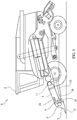
- Fig. 2 illustrates the feeder house, header adapter and first and second actuator of the agricultural harvester according to the invention in more detail.
- the agricultural harvester of fig. 1 comprises a harvester body 2, a header 5 and a feeder house 3. Between the header 5 and the feeder house 3, a header adapter 4 is arranged.
- the header 5 is adapted for harvesting a crop from the field on which said crop was grown.
- the header 5 can for example be equipped a harvester device 12, e.g. comprising a mower or stalk puller.
- a harvester device 12 e.g. comprising a mower or stalk puller.
- the now harvested crop is transported by a header conveyor from the harvester device to a header discharge 14.
- the header discharge 14 is where the harvested crop leaves the header.
- the header conveyor can for example be a header auger 6.
- the feeder house 3 is adapted to receive the harvested crop from the header, e.g. from the header discharge to which the header auger 6 has transported the harvested crop.
- the feeder house 3 generally contains a feeder conveyor 7 (see fig. 2 ) that transports the harvested crop further into the harvester body 2 of the agricultural harvester 1.
- the feeder house conveyor 7 for example comprises a header side cylindrical drum 8, a body side cylindrical drum 9 and one or more chains or belts 10.
- the header side cylindrical drum 8 is a cylindrical drum which is arranged in the feeder house adjacent to the header discharge.
- the harvester body 2 of the agricultural harvester optionally contains at least one crop processing device, for example a thresher, a sieving device and/or a cutter device.
- the harvester body 2 optionally also comprises a grain tank in which the harvested crop is temporarily stored. The grain tank is emptied periodically.
- the feeder house 3 is pivotable relative to the harvester body 2 about pivot 11.
- the header adapter 4 is arranged between the header 5 and the feeder house 3. It is connected to the header 5 and to the feeder house 3.
- the header adapter 4 is adapted to allow the header 5 to pivot relative to the feeder house 3.
- the header adapter 4 is fixedly connected to the header 5 and pivotably connected to the feeder house 3.
- An adapter pivot 20 provides this pivotable connection of the header adapter 4 to the feeder house 3.
- the adapter pivot 20 is adapted to allow pivoting of the header 5 relative to the feeder house 3 about a horizontal pivot axis which extends substantially parallel to the longitudinal axis of the header 5.
- two adapter pivot 20 are present: one on the left side of the feeder house 3 and one on the right side of the feeder house.
- the agricultural harvester 1 further comprises a first actuator 21.
- the first actuator 21 which has a first end 22 which is pivotably connected to the feeder house 3 and a second end 23 which is pivotably connected to the header adapter 4.
- the agricultural harvester 1 further comprises a second actuator 25, which has a first end 26 and a second end 27, which first end 26 is pivotably connected to the harvester body 2.
- the second actuator 25 may be used to pivot the feeder house 3 relative to the harvester body 2, but it can also assist in pivoting the header 5 relative to the feeder house 3.
- the first actuator 21 is adapted to pivot the header 5 relative to the feeder house 3 by pivoting the header adapter 4 relative to the feeder house 3.
- the second actuator 25 optionally assists the first actuator 21 with this pivoting.
- the agricultural harvester 1 further comprises a coupling device 30 which is pivotably connected to the second end 27 of the second actuator 25, the feeder house 3 and the header adapter 4.
- the adapter pivot 20 is the only weight bearing connection between the header adapter 4 and the feeder house 3.
- Fig. 2 clearly shows that in the agricultural harvester according to the invention, also the second actuator 25 bears part of the weight of the header adapter 4 and header 5 - and if the feeder house 3 is pivotably connected to the harvester body 2, also part of the weight of the feeder house - via the coupling device 30.
- the adapter pivot 20 can be of lighter construction.
- the adapter pivot 20 is arranged in a plane 40 that extends through the longitudinal center line of the header auger 6 and through the longitudinal center line of the cylindrical drum 8 of the feeder house conveyor 7, which cylindrical drum 8 is arranged in the feeder house 3 adjacent to the header discharge 14.
- the distance between the header auger 6 and the header side cylindrical drum 8 remains the same, so that an efficient transfer of harvested crop from the header 5 to the feeder house 3 remains ensured.
- connection between the second end 23 of the first actuator 21 and the header adapter 4 is arranged on a first side of a horizontal plane through the horizontal pivot axis of the adapter pivot 20 and the connection between the coupling device 30 and the header adapter 4 is arranged on a second side of a horizontal plane through the adapter pivot 20, which second side is opposite to the first side.
- connection between the second end 23 of the first actuator 21 and the header adapter 4 is arranged above the adapter pivot 20, and the connection between the coupling device 30 and the header adapter 4 is arranged below the adapter pivot 20.
- connection between the second end 23 of the first actuator 21 and the header adapter 4 is arranged near the top of the header adapter 4.
- the connection between the coupling device 30 and the header adapter 4 is arranged near the bottom of the header adapter 4.
- the arm of the pivot moment that is exerted by the first actuator 21 and the second actuator 25 is rather large.
- the force that has to be delivered by the actuators to effect the pivoting of the header adapter 4 and the header 5 relative to the feeder house 3 can be kept relatively small.
- the distance between the connection between the second end 23 of the first actuator 21 and the header adapter 4 on the one hand and the connection between the coupling device 30 and the header adapter 4 on the other hand is at least 75% of the height of the header adapter 4.
- the coupling device 30 is a coupling mechanism.
- the coupling mechanism comprises at least two links 31, 32 that are pivotable relative to each other.
- the mechanism allows to prescribe a desired path of relative movement of the feeder house 3 and the header adapter 4.
- the coupling device 30 is pivotably connected to the second end 27 of the second actuator 25 via a first coupling pivot 35.
- the coupling device 30 is pivotably connected to the feeder house 3 via a second coupling pivot 36.
- the coupling device 30 is pivotably connected to the header adapter 4 via a third coupling pivot 37.
- a coupling mechanism pivot 38 is present within the coupling device 30.
- the first link 31 is a lever which has three pivots: the first coupling pivot 35, the second coupling pivot 36 and a coupling mechanism pivot 38 that pivotably connects the first link with the second link 32.
- the links have fixed distances between the pivot points. In a different embodiment however, at least one of the links could have an adjustable distance between at least two of the pivots.
Landscapes
- Life Sciences & Earth Sciences (AREA)
- Environmental Sciences (AREA)
- Engineering & Computer Science (AREA)
- Mechanical Engineering (AREA)
- Soil Sciences (AREA)
- Harvester Elements (AREA)
Claims (8)
- Landwirtschaftliche Erntemaschine mit:- einem Erntemaschinenaufbau (2),- einem Vorsatz (5), der dazu eingerichtet ist, das Erntegut von einem Feld, auf dem das Erntegut angebaut wurde, zu ernten;- einem Förderergehäuse (3), das dazu eingerichtet ist, das geerntete Erntegut von dem Vorsatz (5) zu empfangen,- einem Vorsatzadapter (4), der zwischen dem Vorsatz (5) und dem Förderergehäuse (3) angeordnet ist und mit dem Vorsatz (5) und dem Förderergehäuse (3) verbunden ist, wobei der Vorsatzadapter (4) dazu eingerichtet ist, dass der Vorsatz (5) sich entlang einer horizontalen Drehachse, die sich im Wesentlichen parallel zu der Längsachse des Vorsatzes (5) erstreckt, relativ zu dem Förderergehäuse (3) drehen kann,- einem ersten Bestätigungselement (21) mit einem ersten Ende (22), das drehbar mit dem Förderergehäuse (3) verbunden ist, und einem zweiten Ende (23), das drehbar mit dem Vorsatzadapter (4) verbunden ist,- einem zweiten Bestätigungselement (25) mit einem ersten Ende (26) und einem zweiten Ende (27), wobei das erste Ende drehbar mit dem Erntemaschinenaufbau (2) verbunden ist,- einer Kopplungseinrichtung (30), die drehbar mit dem zweiten Ende (27) des zweiten Betätigungselements (25) und dem Vorsatzadapter (4) verbunden ist, dadurch gekennzeichnet, dass die Kopplungseinrichtung des Weiteren drehbar mit dem Förderergehäuse (3) verbunden ist.
- Landwirtschaftliche Erntemaschine nach Anspruch 1,
wobei der Vorsatzadapter (4) mittels eines Adaptergelenks (20) drehbar mit dem Förderergehäuse (3) verbunden ist, wobei das Adaptergelenk (20) dazu eingerichtet ist, das Drehen des Vorsatzes (5) relativ zu dem Förderergehäuse (3) entlang einer horizontalen Drehachse, die sich im Wesentlichen parallel zu der Längsachse des Vorsatzes (5) erstreckt, zu ermöglichen. - Landwirtschaftliche Erntemaschine nach Anspruch 2,
wobei die Verbindung zwischen dem zweiten Ende (23) des ersten Betätigungselements (21) und dem Vorsatzadapter (4) auf einer ersten Seite einer horizontalen Ebene durch die horizontale Drehachse des Adaptergelenks (20) angeordnet ist, und die Verbindung zwischen der Kopplungseinrichtung (30) und dem Vorsatzadapter (4) auf einer zweiten Seite einer horizontalen Ebene durch das Adaptergelenk angeordnet ist, wobei die zweite Seite der ersten Seite gegenüber liegt. - Landwirtschaftliche Erntemaschine nach einem der vorhergehenden Ansprüche,
wobei der Abstand zwischen der Verbindung zwischen dem zweiten Ende (22) des ersten Betätigungselements (21) und dem Vorsatzadapter (4) auf der einen Seite und der Verbindung zwischen der Kopplungseinrichtung (30) und dem Vorsatzadapter (4) auf der anderen Seite mindestens 75 % der Höhe des Vorsatzadapters (4) entspricht. - Landwirtschaftliche Erntemaschine nach einem der vorhergehenden Ansprüche,
wobei die Kopplungseinrichtung (30) ein Kopplungsmechanismus ist, der mindestens zwei Glieder (31, 32) aufweist, die relativ zueinander drehbar sind. - Landwirtschaftliche Erntemaschine nach Anspruch 5,
wobei jedes Glied (31, 32) mindestens zwei Drehpunkte (35, 36, 37, 38) aufweist, wobei jeder Drehpunkt drehbar die Glieder mit einem des zweiten Endes (27) des zweiten Betätigungselements (25), des Förderergehäuses (3), des Vorsatzadapters (4) oder eines anderen Glieds (31, 32) des Kopplungsmechanismus verbindet,
und
wobei bei mindestens einem Glied des Kopplungsmechanismus der Abstand zwischen mindestens zwei Drehpunkten des Gliedes einstellbar ist. - Landwirtschaftliche Erntemaschine nach einem der vorhergehenden Ansprüche,
wobei die Kopplungseinrichtung (30) durch einen ersten Kopplungsdrehpunkt (35) schwenkbar mit dem zweiten Ende (27) des zweiten Betätigungselements (25) verbunden ist, und durch einen zweiten Kopplungsdrehpunkt (36) drehbar mit dem Förderergehäuse (3) verbunden ist, und durch einen dritten Kopplungsdrehpunkt (37) drehbar mit dem Vorsatzadapter (4) verbunden ist. - Landwirtschaftliche Erntemaschine nach Anspruch 2,
wobei der Vorsatz (5) eine Erntevorrichtung (12) zum Ernten eines Ernteguts von dem Feld, auf dem es angebaut wurde, und einen Vorsatzförderer zum Aufnehmen des geernteten Ernteguts von der Erntevorrichtung und Transportieren des Ernteguts zu einem Vorsatzauslass (14) aufweist, und
wobei das Förderergehäuse (3) ein Förderergehäuse-Förderband (7) aufweist, das angeordnet ist, um das geerntete Erntegut von dem Vorsatzauslass (14) aufzunehmen, und
wobei der Vorsatzförderer einen Vorsatzschneckenförderer (6) aufweist und das Förderergehäuse-Förderband (7) eine zylindrische Trommel (8) aufweist, die angrenzend an den Vorsatzauslass (14) angeordnet ist,
und wobei das Adaptergelenk (20) in einer Ebene angeordnet ist, die sich durch die Längsmittelachse des Vorsatzschneckenförderers (6) und durch die Längsmittelachse der zylindrischen Trommel (8) des Förderergehäuse-Förderbandes (7) erstreckt.
Applications Claiming Priority (1)
| Application Number | Priority Date | Filing Date | Title |
|---|---|---|---|
| BE2014/0825A BE1022551B1 (nl) | 2014-11-27 | 2014-11-27 | Oogstmachine voor gebruik in de landbouw |
Publications (2)
| Publication Number | Publication Date |
|---|---|
| EP3025575A1 EP3025575A1 (de) | 2016-06-01 |
| EP3025575B1 true EP3025575B1 (de) | 2017-10-25 |
Family
ID=52807448
Family Applications (1)
| Application Number | Title | Priority Date | Filing Date |
|---|---|---|---|
| EP15196587.8A Active EP3025575B1 (de) | 2014-11-27 | 2015-11-26 | Landwirtschaftliche erntemaschine |
Country Status (4)
| Country | Link |
|---|---|
| US (1) | US9730375B2 (de) |
| EP (1) | EP3025575B1 (de) |
| BE (1) | BE1022551B1 (de) |
| BR (1) | BR102015029286B1 (de) |
Cited By (1)
| Publication number | Priority date | Publication date | Assignee | Title |
|---|---|---|---|---|
| US20220256769A1 (en) * | 2019-07-19 | 2022-08-18 | Agco Do Brasil Soluções Agrícolas Ltda | Feederhouse assemblies, agricultural harvesters, and methods of connecting harvesting headers to agricultural harvesters |
Families Citing this family (19)
| Publication number | Priority date | Publication date | Assignee | Title |
|---|---|---|---|---|
| GB201607568D0 (en) * | 2016-04-29 | 2016-06-15 | Agco Do Brazil Com E Ind Ltda | Harvester header pitch adjustment apparatus |
| US10405474B2 (en) * | 2017-04-30 | 2019-09-10 | Deere & Company | Multilink connection between harvesting head adapter frame and mainframe |
| BR102017010857A2 (pt) * | 2017-05-24 | 2018-12-18 | CNH Industrial Brasil Ltda. | conjunto estrutural para montagem de uma plataforma e máquina colhedora |
| BR102017010859B1 (pt) * | 2017-05-24 | 2022-12-13 | Cnh Industrial Brasil Ltda | Conjunto estrutural para montagem de uma plataforma |
| US10517215B2 (en) * | 2017-10-12 | 2019-12-31 | Deere & Company | Roll center for attachment frame control arms |
| US10813289B2 (en) * | 2018-06-05 | 2020-10-27 | Deere & Company | Single top beam folding corn head mainframe |
| DE102018212075A1 (de) * | 2018-07-19 | 2020-01-23 | Deere & Company | Mähdrescher mit einem Schrägförderer mit aktorisch verstellbarer, unterer Umlenkwalze |
| US11032970B2 (en) * | 2018-10-30 | 2021-06-15 | Deere & Company | Varying a hydraulic cylinder mechanical advantage to obtain smoother float pressure |
| US11483970B2 (en) * | 2018-11-28 | 2022-11-01 | Cnh Industrial America Llc | System and method for adjusting the orientation of an agricultural harvesting implement based on implement height |
| EP3669633B1 (de) * | 2018-12-18 | 2022-02-09 | CNH Industrial Belgium NV | Kopfantriebsmechanismus für einen mähdrescher |
| US11140825B2 (en) * | 2019-01-04 | 2021-10-12 | Deere & Company | Header positioning assembly for agricultural work vehicle |
| US11116133B2 (en) * | 2019-01-04 | 2021-09-14 | Deere & Company | Header positioning assembly for an agricultural work vehicle and control system for the same |
| US11497164B2 (en) * | 2019-10-22 | 2022-11-15 | Cnh Industrial America Llc | Header suspension for pivoting header of combine harvester |
| DE102020115944A1 (de) * | 2020-06-17 | 2021-12-23 | Claas Selbstfahrende Erntemaschinen Gmbh | Feldhäcksler |
| US12520762B2 (en) | 2021-06-15 | 2026-01-13 | Cnh Industrial America Llc | System and method for adjusting the position of a harvesting implement of an agricultural harvester |
| US12102038B2 (en) * | 2021-08-19 | 2024-10-01 | Cnh Industrial America Llc | Apparatus and method for adjusting faceplate of feeder for agricultural vehicle |
| US12532808B2 (en) * | 2022-06-24 | 2026-01-27 | Cnh Industrial America Llc | Passive header tilt control for rigid-mode operation with friction-controlling cylinders |
| US12543644B2 (en) | 2023-01-17 | 2026-02-10 | Cnh Industrial America Llc | Feeder housing with torque stops for agricultural vehicle |
| CN118235609B (zh) * | 2024-05-08 | 2024-11-29 | 农业农村部南京农业机械化研究所 | 一种三角履带式高地隙居中铺放油菜割晒机 |
Family Cites Families (16)
| Publication number | Priority date | Publication date | Assignee | Title |
|---|---|---|---|---|
| US4313294A (en) * | 1980-09-11 | 1982-02-02 | Sperry Corporation | Constant float attachment apparatus |
| DD233921A1 (de) * | 1985-01-22 | 1986-03-19 | Fortschritt Veb K | Adapteraufhaengung am maehdrescher |
| US4707972A (en) * | 1985-06-19 | 1987-11-24 | New Holland Inc. | Movable feeder floor for combines |
| DE4223026A1 (de) | 1992-07-14 | 1994-01-27 | Schumacher Gmbh Geb | Neigungseinrichtung für eine pendelnd gelagerte Baugruppe an einer landwirtschaftlichen Maschine |
| DE4324766A1 (de) * | 1993-07-23 | 1995-01-26 | Maehdrescherwerke Ag | Einrichtung zur Lagereglung eines Schneidwerkes |
| CH689077A5 (de) | 1995-09-01 | 1998-09-15 | Schwaninger Kurt Ag | Hang-Maehdrescher. |
| US6116008A (en) | 1999-04-01 | 2000-09-12 | New Holland North America, Inc. | Pivoting faceplate for a feederhouse on an agricultural combine |
| DE19958341A1 (de) | 1999-12-03 | 2001-07-12 | Claas Industrietechnik Gmbh | Erntemaschine mit frontseitig angebautem Erntevorsatz |
| DE10018211A1 (de) | 2000-04-12 | 2001-11-22 | Claas Selbstfahr Erntemasch | Landwirtschaftliche Erntemaschine |
| DE10227484A1 (de) | 2002-06-19 | 2004-02-26 | Claas Selbstfahrende Erntemaschinen Gmbh | Vorrichtung und Verfahren zur Lagesteuerung eines Erntegutaufnahmegerätes landwirtschaftlicher Erntemaschinen |
| US7191582B2 (en) | 2005-05-10 | 2007-03-20 | Deere & Company | Header terrain following system |
| US20070294990A1 (en) | 2006-06-26 | 2007-12-27 | Deere & Company, A Delaware Corporation. | Locking harvester header lift cylinder |
| US8079204B2 (en) | 2008-09-22 | 2011-12-20 | Deere & Company | Feeder house twist dampening system |
| US8966871B2 (en) | 2011-12-28 | 2015-03-03 | Agco Corporation | Automatic roll-back and return-to-position for header tilt on an agricultural machine |
| US8881495B2 (en) | 2011-12-28 | 2014-11-11 | Agco Corporation | Front and rear ground sensing for header pitch control |
| US8826635B2 (en) | 2013-02-06 | 2014-09-09 | Deere & Company | Combine harvester with feederhouse arrangement |
-
2014
- 2014-11-27 BE BE2014/0825A patent/BE1022551B1/nl active
-
2015
- 2015-11-19 US US14/946,051 patent/US9730375B2/en not_active Expired - Fee Related
- 2015-11-23 BR BR102015029286-4A patent/BR102015029286B1/pt active IP Right Grant
- 2015-11-26 EP EP15196587.8A patent/EP3025575B1/de active Active
Non-Patent Citations (1)
| Title |
|---|
| None * |
Cited By (1)
| Publication number | Priority date | Publication date | Assignee | Title |
|---|---|---|---|---|
| US20220256769A1 (en) * | 2019-07-19 | 2022-08-18 | Agco Do Brasil Soluções Agrícolas Ltda | Feederhouse assemblies, agricultural harvesters, and methods of connecting harvesting headers to agricultural harvesters |
Also Published As
| Publication number | Publication date |
|---|---|
| US20160150716A1 (en) | 2016-06-02 |
| US9730375B2 (en) | 2017-08-15 |
| BR102015029286A2 (pt) | 2016-05-31 |
| BE1022551B1 (nl) | 2016-05-31 |
| BR102015029286B1 (pt) | 2020-11-17 |
| EP3025575A1 (de) | 2016-06-01 |
Similar Documents
| Publication | Publication Date | Title |
|---|---|---|
| US9730375B2 (en) | Agricultural harvester | |
| AU2018201075B2 (en) | Combination flex and rigid header height control in a harvester | |
| US9750187B2 (en) | Adjustable row unit deck plate for a header of an agricultural harvester | |
| CN109379981B (zh) | 可折叠玉米割头 | |
| US10694654B2 (en) | Automatic divider height positioning for an agricultural harvester | |
| US20220000029A1 (en) | Remotely adjustable row divider for an agricultural harvester | |
| US11622505B2 (en) | Agricultural header with constant reel to cutter relationship | |
| JP2011200188A (ja) | コンバイン | |
| JP6436884B2 (ja) | 収穫機 | |
| US9609805B2 (en) | Folding auger assembly for an agricultural harvester | |
| JP2009189272A (ja) | コンバインの刈取前処理構造 | |
| JP2013183680A (ja) | コンバインの前処理装置 | |
| JP2010022320A (ja) | 普通型コンバイン | |
| CA3072370C (en) | Agricultural header with constant reel to cutter relationship | |
| US8821228B1 (en) | Dual bin combine system | |
| JP2019103406A (ja) | コンバイン | |
| US10729057B2 (en) | Integrated upright header transport for an agricultural combine | |
| JP6373131B2 (ja) | 収穫機 | |
| EA042268B1 (ru) | Жатка зерноуборочного комбайна | |
| JP2007029026A (ja) | コンバイン | |
| JP2006320279A (ja) | コンバイン | |
| JP2001292621A (ja) | コンバインの刈取機支持装置 | |
| JP2019103405A (ja) | コンバイン | |
| JP2017212948A (ja) | コンバイン | |
| JPH0416116A (ja) | コンバインの刈取部 |
Legal Events
| Date | Code | Title | Description |
|---|---|---|---|
| PUAI | Public reference made under article 153(3) epc to a published international application that has entered the european phase |
Free format text: ORIGINAL CODE: 0009012 |
|
| AK | Designated contracting states |
Kind code of ref document: A1 Designated state(s): AL AT BE BG CH CY CZ DE DK EE ES FI FR GB GR HR HU IE IS IT LI LT LU LV MC MK MT NL NO PL PT RO RS SE SI SK SM TR |
|
| AX | Request for extension of the european patent |
Extension state: BA ME |
|
| STAA | Information on the status of an ep patent application or granted ep patent |
Free format text: STATUS: REQUEST FOR EXAMINATION WAS MADE |
|
| 17P | Request for examination filed |
Effective date: 20161201 |
|
| RBV | Designated contracting states (corrected) |
Designated state(s): AL AT BE BG CH CY CZ DE DK EE ES FI FR GB GR HR HU IE IS IT LI LT LU LV MC MK MT NL NO PL PT RO RS SE SI SK SM TR |
|
| RIC1 | Information provided on ipc code assigned before grant |
Ipc: A01D 41/16 20060101ALI20170412BHEP Ipc: A01D 41/14 20060101AFI20170412BHEP |
|
| GRAP | Despatch of communication of intention to grant a patent |
Free format text: ORIGINAL CODE: EPIDOSNIGR1 |
|
| STAA | Information on the status of an ep patent application or granted ep patent |
Free format text: STATUS: GRANT OF PATENT IS INTENDED |
|
| INTG | Intention to grant announced |
Effective date: 20170523 |
|
| GRAS | Grant fee paid |
Free format text: ORIGINAL CODE: EPIDOSNIGR3 |
|
| GRAA | (expected) grant |
Free format text: ORIGINAL CODE: 0009210 |
|
| STAA | Information on the status of an ep patent application or granted ep patent |
Free format text: STATUS: THE PATENT HAS BEEN GRANTED |
|
| AK | Designated contracting states |
Kind code of ref document: B1 Designated state(s): AL AT BE BG CH CY CZ DE DK EE ES FI FR GB GR HR HU IE IS IT LI LT LU LV MC MK MT NL NO PL PT RO RS SE SI SK SM TR |
|
| REG | Reference to a national code |
Ref country code: GB Ref legal event code: FG4D |
|
| REG | Reference to a national code |
Ref country code: CH Ref legal event code: EP |
|
| REG | Reference to a national code |
Ref country code: FR Ref legal event code: PLFP Year of fee payment: 3 |
|
| REG | Reference to a national code |
Ref country code: AT Ref legal event code: REF Ref document number: 938984 Country of ref document: AT Kind code of ref document: T Effective date: 20171115 |
|
| REG | Reference to a national code |
Ref country code: IE Ref legal event code: FG4D |
|
| REG | Reference to a national code |
Ref country code: DE Ref legal event code: R096 Ref document number: 602015005582 Country of ref document: DE |
|
| REG | Reference to a national code |
Ref country code: NL Ref legal event code: MP Effective date: 20171025 |
|
| REG | Reference to a national code |
Ref country code: LT Ref legal event code: MG4D |
|
| REG | Reference to a national code |
Ref country code: AT Ref legal event code: MK05 Ref document number: 938984 Country of ref document: AT Kind code of ref document: T Effective date: 20171025 |
|
| PG25 | Lapsed in a contracting state [announced via postgrant information from national office to epo] |
Ref country code: NL Free format text: LAPSE BECAUSE OF FAILURE TO SUBMIT A TRANSLATION OF THE DESCRIPTION OR TO PAY THE FEE WITHIN THE PRESCRIBED TIME-LIMIT Effective date: 20171025 |
|
| PG25 | Lapsed in a contracting state [announced via postgrant information from national office to epo] |
Ref country code: NO Free format text: LAPSE BECAUSE OF FAILURE TO SUBMIT A TRANSLATION OF THE DESCRIPTION OR TO PAY THE FEE WITHIN THE PRESCRIBED TIME-LIMIT Effective date: 20180125 Ref country code: LT Free format text: LAPSE BECAUSE OF FAILURE TO SUBMIT A TRANSLATION OF THE DESCRIPTION OR TO PAY THE FEE WITHIN THE PRESCRIBED TIME-LIMIT Effective date: 20171025 Ref country code: ES Free format text: LAPSE BECAUSE OF FAILURE TO SUBMIT A TRANSLATION OF THE DESCRIPTION OR TO PAY THE FEE WITHIN THE PRESCRIBED TIME-LIMIT Effective date: 20171025 Ref country code: SE Free format text: LAPSE BECAUSE OF FAILURE TO SUBMIT A TRANSLATION OF THE DESCRIPTION OR TO PAY THE FEE WITHIN THE PRESCRIBED TIME-LIMIT Effective date: 20171025 Ref country code: FI Free format text: LAPSE BECAUSE OF FAILURE TO SUBMIT A TRANSLATION OF THE DESCRIPTION OR TO PAY THE FEE WITHIN THE PRESCRIBED TIME-LIMIT Effective date: 20171025 |
|
| PG25 | Lapsed in a contracting state [announced via postgrant information from national office to epo] |
Ref country code: RS Free format text: LAPSE BECAUSE OF FAILURE TO SUBMIT A TRANSLATION OF THE DESCRIPTION OR TO PAY THE FEE WITHIN THE PRESCRIBED TIME-LIMIT Effective date: 20171025 Ref country code: BG Free format text: LAPSE BECAUSE OF FAILURE TO SUBMIT A TRANSLATION OF THE DESCRIPTION OR TO PAY THE FEE WITHIN THE PRESCRIBED TIME-LIMIT Effective date: 20180125 Ref country code: LV Free format text: LAPSE BECAUSE OF FAILURE TO SUBMIT A TRANSLATION OF THE DESCRIPTION OR TO PAY THE FEE WITHIN THE PRESCRIBED TIME-LIMIT Effective date: 20171025 Ref country code: AT Free format text: LAPSE BECAUSE OF FAILURE TO SUBMIT A TRANSLATION OF THE DESCRIPTION OR TO PAY THE FEE WITHIN THE PRESCRIBED TIME-LIMIT Effective date: 20171025 Ref country code: HR Free format text: LAPSE BECAUSE OF FAILURE TO SUBMIT A TRANSLATION OF THE DESCRIPTION OR TO PAY THE FEE WITHIN THE PRESCRIBED TIME-LIMIT Effective date: 20171025 Ref country code: GR Free format text: LAPSE BECAUSE OF FAILURE TO SUBMIT A TRANSLATION OF THE DESCRIPTION OR TO PAY THE FEE WITHIN THE PRESCRIBED TIME-LIMIT Effective date: 20180126 Ref country code: IS Free format text: LAPSE BECAUSE OF FAILURE TO SUBMIT A TRANSLATION OF THE DESCRIPTION OR TO PAY THE FEE WITHIN THE PRESCRIBED TIME-LIMIT Effective date: 20180225 |
|
| REG | Reference to a national code |
Ref country code: DE Ref legal event code: R097 Ref document number: 602015005582 Country of ref document: DE |
|
| PG25 | Lapsed in a contracting state [announced via postgrant information from national office to epo] |
Ref country code: CZ Free format text: LAPSE BECAUSE OF FAILURE TO SUBMIT A TRANSLATION OF THE DESCRIPTION OR TO PAY THE FEE WITHIN THE PRESCRIBED TIME-LIMIT Effective date: 20171025 Ref country code: SK Free format text: LAPSE BECAUSE OF FAILURE TO SUBMIT A TRANSLATION OF THE DESCRIPTION OR TO PAY THE FEE WITHIN THE PRESCRIBED TIME-LIMIT Effective date: 20171025 Ref country code: CY Free format text: LAPSE BECAUSE OF FAILURE TO SUBMIT A TRANSLATION OF THE DESCRIPTION OR TO PAY THE FEE WITHIN THE PRESCRIBED TIME-LIMIT Effective date: 20171025 Ref country code: MC Free format text: LAPSE BECAUSE OF FAILURE TO SUBMIT A TRANSLATION OF THE DESCRIPTION OR TO PAY THE FEE WITHIN THE PRESCRIBED TIME-LIMIT Effective date: 20171025 Ref country code: EE Free format text: LAPSE BECAUSE OF FAILURE TO SUBMIT A TRANSLATION OF THE DESCRIPTION OR TO PAY THE FEE WITHIN THE PRESCRIBED TIME-LIMIT Effective date: 20171025 Ref country code: DK Free format text: LAPSE BECAUSE OF FAILURE TO SUBMIT A TRANSLATION OF THE DESCRIPTION OR TO PAY THE FEE WITHIN THE PRESCRIBED TIME-LIMIT Effective date: 20171025 |
|
| PG25 | Lapsed in a contracting state [announced via postgrant information from national office to epo] |
Ref country code: RO Free format text: LAPSE BECAUSE OF FAILURE TO SUBMIT A TRANSLATION OF THE DESCRIPTION OR TO PAY THE FEE WITHIN THE PRESCRIBED TIME-LIMIT Effective date: 20171025 Ref country code: PL Free format text: LAPSE BECAUSE OF FAILURE TO SUBMIT A TRANSLATION OF THE DESCRIPTION OR TO PAY THE FEE WITHIN THE PRESCRIBED TIME-LIMIT Effective date: 20171025 Ref country code: LU Free format text: LAPSE BECAUSE OF NON-PAYMENT OF DUE FEES Effective date: 20171126 Ref country code: SM Free format text: LAPSE BECAUSE OF FAILURE TO SUBMIT A TRANSLATION OF THE DESCRIPTION OR TO PAY THE FEE WITHIN THE PRESCRIBED TIME-LIMIT Effective date: 20171025 |
|
| PLBE | No opposition filed within time limit |
Free format text: ORIGINAL CODE: 0009261 |
|
| STAA | Information on the status of an ep patent application or granted ep patent |
Free format text: STATUS: NO OPPOSITION FILED WITHIN TIME LIMIT |
|
| REG | Reference to a national code |
Ref country code: IE Ref legal event code: MM4A |
|
| PG25 | Lapsed in a contracting state [announced via postgrant information from national office to epo] |
Ref country code: MT Free format text: LAPSE BECAUSE OF NON-PAYMENT OF DUE FEES Effective date: 20171126 |
|
| 26N | No opposition filed |
Effective date: 20180726 |
|
| REG | Reference to a national code |
Ref country code: FR Ref legal event code: PLFP Year of fee payment: 4 |
|
| PG25 | Lapsed in a contracting state [announced via postgrant information from national office to epo] |
Ref country code: IE Free format text: LAPSE BECAUSE OF NON-PAYMENT OF DUE FEES Effective date: 20171126 |
|
| PG25 | Lapsed in a contracting state [announced via postgrant information from national office to epo] |
Ref country code: SI Free format text: LAPSE BECAUSE OF FAILURE TO SUBMIT A TRANSLATION OF THE DESCRIPTION OR TO PAY THE FEE WITHIN THE PRESCRIBED TIME-LIMIT Effective date: 20171025 |
|
| PG25 | Lapsed in a contracting state [announced via postgrant information from national office to epo] |
Ref country code: HU Free format text: LAPSE BECAUSE OF FAILURE TO SUBMIT A TRANSLATION OF THE DESCRIPTION OR TO PAY THE FEE WITHIN THE PRESCRIBED TIME-LIMIT; INVALID AB INITIO Effective date: 20151126 |
|
| REG | Reference to a national code |
Ref country code: CH Ref legal event code: PL |
|
| PG25 | Lapsed in a contracting state [announced via postgrant information from national office to epo] |
Ref country code: LI Free format text: LAPSE BECAUSE OF NON-PAYMENT OF DUE FEES Effective date: 20181130 Ref country code: CH Free format text: LAPSE BECAUSE OF NON-PAYMENT OF DUE FEES Effective date: 20181130 |
|
| PG25 | Lapsed in a contracting state [announced via postgrant information from national office to epo] |
Ref country code: MK Free format text: LAPSE BECAUSE OF FAILURE TO SUBMIT A TRANSLATION OF THE DESCRIPTION OR TO PAY THE FEE WITHIN THE PRESCRIBED TIME-LIMIT Effective date: 20171025 |
|
| PG25 | Lapsed in a contracting state [announced via postgrant information from national office to epo] |
Ref country code: TR Free format text: LAPSE BECAUSE OF FAILURE TO SUBMIT A TRANSLATION OF THE DESCRIPTION OR TO PAY THE FEE WITHIN THE PRESCRIBED TIME-LIMIT Effective date: 20171025 |
|
| PG25 | Lapsed in a contracting state [announced via postgrant information from national office to epo] |
Ref country code: PT Free format text: LAPSE BECAUSE OF FAILURE TO SUBMIT A TRANSLATION OF THE DESCRIPTION OR TO PAY THE FEE WITHIN THE PRESCRIBED TIME-LIMIT Effective date: 20171025 |
|
| PG25 | Lapsed in a contracting state [announced via postgrant information from national office to epo] |
Ref country code: AL Free format text: LAPSE BECAUSE OF FAILURE TO SUBMIT A TRANSLATION OF THE DESCRIPTION OR TO PAY THE FEE WITHIN THE PRESCRIBED TIME-LIMIT Effective date: 20171025 |
|
| PGFP | Annual fee paid to national office [announced via postgrant information from national office to epo] |
Ref country code: BE Payment date: 20241126 Year of fee payment: 10 |
|
| PGFP | Annual fee paid to national office [announced via postgrant information from national office to epo] |
Ref country code: GB Payment date: 20241126 Year of fee payment: 10 |
|
| PGFP | Annual fee paid to national office [announced via postgrant information from national office to epo] |
Ref country code: DE Payment date: 20251126 Year of fee payment: 11 |
|
| PGFP | Annual fee paid to national office [announced via postgrant information from national office to epo] |
Ref country code: IT Payment date: 20251121 Year of fee payment: 11 |
|
| PGFP | Annual fee paid to national office [announced via postgrant information from national office to epo] |
Ref country code: FR Payment date: 20251124 Year of fee payment: 11 |