EP3025665B1 - Computergestütztes system zum führen eines chirurgischen/diagnostischen instruments im körper eines patienten - Google Patents
Computergestütztes system zum führen eines chirurgischen/diagnostischen instruments im körper eines patienten Download PDFInfo
- Publication number
- EP3025665B1 EP3025665B1 EP15196612.4A EP15196612A EP3025665B1 EP 3025665 B1 EP3025665 B1 EP 3025665B1 EP 15196612 A EP15196612 A EP 15196612A EP 3025665 B1 EP3025665 B1 EP 3025665B1
- Authority
- EP
- European Patent Office
- Prior art keywords
- support element
- patient
- tracking sensor
- optical tracking
- elongated support
- Prior art date
- Legal status (The legal status is an assumption and is not a legal conclusion. Google has not performed a legal analysis and makes no representation as to the accuracy of the status listed.)
- Active
Links
Images


Classifications
-
- A—HUMAN NECESSITIES
- A61—MEDICAL OR VETERINARY SCIENCE; HYGIENE
- A61B—DIAGNOSIS; SURGERY; IDENTIFICATION
- A61B34/00—Computer-aided surgery; Manipulators or robots specially adapted for use in surgery
- A61B34/20—Surgical navigation systems; Devices for tracking or guiding surgical instruments, e.g. for frameless stereotaxis
-
- A—HUMAN NECESSITIES
- A61—MEDICAL OR VETERINARY SCIENCE; HYGIENE
- A61B—DIAGNOSIS; SURGERY; IDENTIFICATION
- A61B18/00—Surgical instruments, devices or methods for transferring non-mechanical forms of energy to or from the body
- A61B18/18—Surgical instruments, devices or methods for transferring non-mechanical forms of energy to or from the body by applying electromagnetic radiation, e.g. microwaves
- A61B18/20—Surgical instruments, devices or methods for transferring non-mechanical forms of energy to or from the body by applying electromagnetic radiation, e.g. microwaves using laser
- A61B2018/2015—Miscellaneous features
- A61B2018/2025—Miscellaneous features with a pilot laser
-
- A—HUMAN NECESSITIES
- A61—MEDICAL OR VETERINARY SCIENCE; HYGIENE
- A61B—DIAGNOSIS; SURGERY; IDENTIFICATION
- A61B34/00—Computer-aided surgery; Manipulators or robots specially adapted for use in surgery
- A61B34/20—Surgical navigation systems; Devices for tracking or guiding surgical instruments, e.g. for frameless stereotaxis
- A61B2034/2046—Tracking techniques
- A61B2034/2048—Tracking techniques using an accelerometer or inertia sensor
-
- A—HUMAN NECESSITIES
- A61—MEDICAL OR VETERINARY SCIENCE; HYGIENE
- A61B—DIAGNOSIS; SURGERY; IDENTIFICATION
- A61B34/00—Computer-aided surgery; Manipulators or robots specially adapted for use in surgery
- A61B34/20—Surgical navigation systems; Devices for tracking or guiding surgical instruments, e.g. for frameless stereotaxis
- A61B2034/2046—Tracking techniques
- A61B2034/2055—Optical tracking systems
- A61B2034/2057—Details of tracking cameras
-
- A—HUMAN NECESSITIES
- A61—MEDICAL OR VETERINARY SCIENCE; HYGIENE
- A61B—DIAGNOSIS; SURGERY; IDENTIFICATION
- A61B90/00—Instruments, implements or accessories specially adapted for surgery or diagnosis and not covered by any of the groups A61B1/00 - A61B50/00, e.g. for luxation treatment or for protecting wound edges
- A61B90/36—Image-producing devices or illumination devices not otherwise provided for
- A61B2090/364—Correlation of different images or relation of image positions in respect to the body
- A61B2090/366—Correlation of different images or relation of image positions in respect to the body using projection of images directly onto the body
-
- A—HUMAN NECESSITIES
- A61—MEDICAL OR VETERINARY SCIENCE; HYGIENE
- A61B—DIAGNOSIS; SURGERY; IDENTIFICATION
- A61B90/00—Instruments, implements or accessories specially adapted for surgery or diagnosis and not covered by any of the groups A61B1/00 - A61B50/00, e.g. for luxation treatment or for protecting wound edges
- A61B90/36—Image-producing devices or illumination devices not otherwise provided for
- A61B90/37—Surgical systems with images on a monitor during operation
- A61B2090/371—Surgical systems with images on a monitor during operation with simultaneous use of two cameras
-
- A—HUMAN NECESSITIES
- A61—MEDICAL OR VETERINARY SCIENCE; HYGIENE
- A61B—DIAGNOSIS; SURGERY; IDENTIFICATION
- A61B90/00—Instruments, implements or accessories specially adapted for surgery or diagnosis and not covered by any of the groups A61B1/00 - A61B50/00, e.g. for luxation treatment or for protecting wound edges
- A61B90/36—Image-producing devices or illumination devices not otherwise provided for
- A61B90/37—Surgical systems with images on a monitor during operation
- A61B2090/373—Surgical systems with images on a monitor during operation using light, e.g. by using optical scanners
-
- A—HUMAN NECESSITIES
- A61—MEDICAL OR VETERINARY SCIENCE; HYGIENE
- A61B—DIAGNOSIS; SURGERY; IDENTIFICATION
- A61B90/00—Instruments, implements or accessories specially adapted for surgery or diagnosis and not covered by any of the groups A61B1/00 - A61B50/00, e.g. for luxation treatment or for protecting wound edges
- A61B90/39—Markers, e.g. radio-opaque or breast lesions markers
- A61B2090/3937—Visible markers
-
- A—HUMAN NECESSITIES
- A61—MEDICAL OR VETERINARY SCIENCE; HYGIENE
- A61B—DIAGNOSIS; SURGERY; IDENTIFICATION
- A61B90/00—Instruments, implements or accessories specially adapted for surgery or diagnosis and not covered by any of the groups A61B1/00 - A61B50/00, e.g. for luxation treatment or for protecting wound edges
- A61B90/39—Markers, e.g. radio-opaque or breast lesions markers
- A61B2090/3983—Reference marker arrangements for use with image guided surgery
-
- A—HUMAN NECESSITIES
- A61—MEDICAL OR VETERINARY SCIENCE; HYGIENE
- A61B—DIAGNOSIS; SURGERY; IDENTIFICATION
- A61B90/00—Instruments, implements or accessories specially adapted for surgery or diagnosis and not covered by any of the groups A61B1/00 - A61B50/00, e.g. for luxation treatment or for protecting wound edges
- A61B90/50—Supports for surgical instruments, e.g. articulated arms
-
- A—HUMAN NECESSITIES
- A61—MEDICAL OR VETERINARY SCIENCE; HYGIENE
- A61B—DIAGNOSIS; SURGERY; IDENTIFICATION
- A61B90/00—Instruments, implements or accessories specially adapted for surgery or diagnosis and not covered by any of the groups A61B1/00 - A61B50/00, e.g. for luxation treatment or for protecting wound edges
- A61B90/90—Identification means for patients or instruments, e.g. tags
Definitions
- the present invention relates to a computer-assisted system for guiding a surgical/diagnostic instrument in the body of a patient.
- a surgical/diagnostic instrument operting tool
- these operations could be biopsies, thermal ablation, removal of damaged tissue, the introduction of chemical/pharmaceutical products into the human body.
- Introduction and subsequent reaching of the target by the surgical/diagnostic instrument can be facilitated by guide, or navigation, systems, of virtual type, based on images of the target and of the areas surrounding the target so as to plan and perform the percutaneous operation in the least invasive way.
- Known navigation/guide systems for operations of the aforesaid type are based on the processing of images acquired previously through computerized tomography CT or magnetic resonance MR and require the definition of a virtual reality three-dimensional reconstruction of the target area of the human body.
- a three-dimensional representation of the surgical/diagnostic instrument is superimposed on the three-dimensional reconstruction and moved on the image following the real movements of the instrument.
- the patent EP09425116 by the same applicant shows a computer-assisted system for guiding a surgical/diagnostic instrument in the body of a patient comprising a first marker device configured to be arranged integral with a region of the body of a patient and including first and second patient markers having a given mutual arrangement; a second marker configured to be coupled to the surgical/diagnostic instrument and including third instrument marker elements; an optical location sensor configured to locate the second and third marker elements in a first reference system; and a processing unit configured to acquire at least one tomography image of the region of the patient's body comprising the first marker elements in un second reference system different from the first, acquire the position of the second and third marker elements in the first reference system, and determine the position of said third marker elements in the second reference system based on a correlation between the first and the second reference systems.
- the optical sensor generally comprises a pair of video cameras adapted to acquire, from different angles, an image of an area of vision in which the working/diagnostic instrument is located.
- US2004147839 describes a method of registering an article having a surface to previously created scan data of the article, the method comprising the steps of: providing a flexible substrate having multiple tracking points attached to the substrate; applying the substrate to the article to be registered; creating a model of the surface of the article from a location of each tracking point; and registering the model with the previously created scan data.
- US5999840 describes an image data registration system comprising: an image data storage unit for storing a first data set of three-dimensional image data associated with a predetermined portion of an object with reference to a first coordinate frame; a first image data acquisition and storage device for obtaining and storing a second data set of three-dimensional image data associated with a surface of said predetermined portion of said object with reference to a second coordinate frame; and a second image data acquisition and storage device for obtaining and storing a third data set of three-dimensional image data associated with a movable probe positioned in close proximity to said predetermined portion of said object with reference to a third coordinate frame; an image data processor for registering said first, second and third data sets of three-dimensional image data to generate a matched image data set of three-dimensional image data in which said first, second and third coordinate frames are relatively aligned with one another.
- the object of the present invention is to improve the system described in the aforesaid patent by producing an optical sensor that can perform further functions, such as scanning functions for the detection of three-dimensional profiles.
- the preceding object is achieved by the present invention as it relates to a computer-assisted system for guiding a surgical/diagnostic instrument in the body of a patient arranged on a support structure as claimed in claim 1.
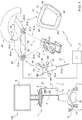
- Fig. 1 shows a system according to the present invention comprising an instrumental station 1; an optical tracking sensor 20 produced according to the present invention and detailed below; in particular, an infrared sensor configured to cooperate with the instrumental station 1; a patient marker 22, provided with infrared marker elements M1 and configured to be arranged on a portion of the body of a patient P and to cooperate with the tracking sensor 20 (as better described hereunder); and an instrument marker 26, provided with a plurality of second infrared marker elements M2 (in the example spheres M2 opaque to infrared radiation that lie on the same plane and that have a predetermined arrangement relative to one another) and configured to be coupled to a surgical instrument 27 to cooperate with the infrared tracking sensor 20 (as better described below).
- the patient is arranged on a supporting structure 7 (typically a stretcher) that prevents shifting of the patient in space.
- the patient is normally anaesthetised or heavily sedated.
- the surgical/diagnostic instrument 27 (in the example of Fig. 1 an endoscopic needle) comprises a grippable proximal portion 25a and an operative distal portion 25b; the instrument marker 26 is coupled to an intermediate portion, leaving the distal portion 25b free. It should be noted that, for greater clarity of representation, the relative sizes of the elements shown in the figures are not proportional to one another.
- the instrumental station 1 ( Fig. 1 ) comprises a processing unit 4, for example a processor of known type provided with a microcontroller 5 and with a memory 7, connected to each other; a data input user interface 6, for example including a keypad and mouse; a viewing interface 8, for example a high resolution LCD monitor; a network interface 10, configured to support a private and/or public network connection 11 (for example an Ethernet network).
- a processing unit 4 for example a processor of known type provided with a microcontroller 5 and with a memory 7, connected to each other
- a viewing interface 8 for example a high resolution LCD monitor
- a network interface 10 configured to support a private and/or public network connection 11 (for example an Ethernet network).
- the instrumental station 1 also comprises a power connection 12, configured to supply the instrumental station 1 with electrical power by means of a wall power socket 13; a tracking input 15, configured to support a connection 17 (either of wireless or wired type) between the instrumental station 1 and the optical tracking sensor 20; and an energy storage unit 18, for example a battery, connected to the wall socket 13 through the power connection 12 and configured to temporarily supply the instrumental station 1 in the event of an outage in the power supplied by the wall socket 13.
- a power connection 12 configured to supply the instrumental station 1 with electrical power by means of a wall power socket 13
- a tracking input 15 configured to support a connection 17 (either of wireless or wired type) between the instrumental station 1 and the optical tracking sensor 20
- an energy storage unit 18, for example a battery connected to the wall socket 13 through the power connection 12 and configured to temporarily supply the instrumental station 1 in the event of an outage in the power supplied by the wall socket 13.
- the processing unit 4 is a personal computer (PC), comprising an external protective casing housed on a shelf of the instrumental station 1 and integral with the instrumental station 1 during any movement of this latter on the wheels 2.
- PC personal computer
- the patient marker 22 is arranged in contact with the patient so as to be integral therewith in a region of the patient (externally) close to the operating region.
- the patient marker 22 in the infrared version of Figs. 1 and 2 comprises a body 31, for example made of plastic material or, more in general, a material transparent to the image acquisition system used.
- the body 31 is in the shape of a trapezoidal frame with the spherical marker elements M1 arranged at the vertex of the trapezoid.
- the shape of the marker element can differ, for example it can be Y-shaped or X-shaped, with the marker elements arranged at the ends of the arms.
- the system operates as described in the patent EP09425116 by the same applicant; in particular, an initialising and calibration step is performed in which CT / MR images of an area of interest are acquired; these images are composited with one another using known algorithms in order to produce a three-dimensional image having its own reference system, the reference system of the three-dimensional image is aligned with that of the sensor 20 and, finally, an operating step is performed in which the processing unit 4 carries out a virtual navigation according to the modes described in EP09425116 using the aforesaid correctly positioned three-dimensional image as three-dimensional model.
- the processing unit 4 allows the following to be viewed on the viewing unit 8:
- a three-dimensional model of the area of the patient being operated on i.e. showing internal organs and tissues, is viewed on the viewing interface 8.
- this three-dimensional model is generated by the processing unit 4.
- the viewing interface 8 also shows a three-dimensional model of the surgical instrument used superimposed on the three-dimensional model of the area of the patient being operated on.
- the type of surgical instrument 25 to be viewed may be chosen by the doctor performing the operation from a plurality of possible models, previously created and stored in the memory 7 of the processing unit 4.
- the doctor manipulating the surgical/diagnostic instrument 27 provided with the instrument marker 26 is guided by the images viewed on the viewing interface 8 throughout the entire operation.
- the trajectory of the surgical/diagnostic instrument 27 is calculated with the aid of artificial-intelligence algorithms so that the whole of the area involved is treated with the minimum number of insertions, ensuring total coverage without striking vital organs and/or obstacles. These organs are identified through the three-dimensional model shown on the viewing interface 8.
- the position of the surgical/diagnostic instrument 27 is entered in the three-dimensional model due to the measurement that the tracking sensor 20 performs on the spatial coordinates of the instrument marker 26.
- the optical tracking sensor 20 comprises:
- the video cameras 42-a and 42-b have respective axes 47-a and 47-b tilted towards each other and converging in an area of view FOV in which the patient P is located.
- the motorized pivot device 45 has at least two degrees of freedom and produces the rotation of the support element 40 relative to the support structure 46 about a first axis (horizontal in the example) 50 (tilt) and according to a second axis 52 (pan) perpendicular to the first.
- the instantaneous value of an angle alpha (relative to a vertical reference) about the tilt axis 50 and the instantaneous value of an angle beta (relative to a vertical reference) about the pan axis is detected by a solid state inertial sensor (inclinometer) 55 (of known type - Fig. 2 ) arranged on the support element 40.
- the signal produced by the inertial sensor 55 is sent to a microprocessor control unit 57 carried by the support element 40 and adapted to drive the actuators (shown below) that produce the rotations about the tilt axis 50 and the pan axis 52.
- Control of the actuators that produce the movement of the pivot device about the tilt axis 50 and about the pan axis 52 enables the area of vision FOV to be moved in space; in particular - as will be explained in more detail below - the area of vision FOV is moved so as to maintain the image of the instrument marker 26 detected by the video camera 42-a/42-b substantially at the centre of the image detected also in the event of shifting of the instrument in order to perform a tracking function of the instrument marker 26 (and therefore of the surgical/diagnostic instrument 27) by the optical tracking sensor 20.
- the implementation of movements about the tilt 50 and pan 52 axes enables the sensor 20 to track the operating tool so that it is always in the FOV, i.e. in the area in which the errors are lowest.
- the support element 40 comprises an elongated metal wall 60 having a pair of integral lips 61 that extend along the longer sides of a flat rectangular central portion 60-c of the elongated wall 60.
- the elongated wall 60 has end portions 60-a, 60-b of the elongated wall 60 of flat type integral with the central portion 60-c and arranged folded by a few degrees relative to the central portion 60-c.
- Each end portion 60-a, 60-b is provided with a circular through hole 62-a, 62-b in which there is housed a respective assembly comprising the first/second video camera 42-a, 42-b and the first/second illuminator 43-a,43-b.
- the unit can comprise a flat wall 64 in the shape of a circular crown supporting, on a first face thereof, the LEDs 65 of the illuminator and provided with a video camera mounted coaxially to the circular crown shaped flat structure 64 (the axis of the video camera is coaxial to the circular crown).
- the first end of the pivot element 45 is stably connected with the central portion 60-c.
- the pivot device 45 comprises a first L-shaped bracket 70 provided with a first flat portion with a shorter side 70-a fastened by means of screws 71 on the central portion 60-b and a second flat portion with a longer side 70-b that carries a first actuator 73 of electrical type provided with a first rotating output member 74 that rotates about the first tilt axis 50.
- the first rotating output member 74 is fixed to a first flat portion of a second L-shaped bracket 75 parallel to the second flat portion 70-b.
- the second L-shaped bracket 75 comprises a second flat portion perpendicular to the first and fixed to an end portion of a second rotating output member (not visible in the figures) of a second electrical actuator 77.
- the second rotating output member extends from a casing of the second actuator 77 and rotates about the pan axis 52.
- the casing of the second actuator 77 is integral with a tubular sleeve 78, the circular end flange 79 of which produces the second end of the pivot 45.
- the pivot device 45 produced according to the present invention comprises a limited number of parts and for this reason is simple to produce, is rustic and sturdy and has limited costs. Moreover, the sizes of the pivot device 45 are limited.
- the sensor 20 comprises an external protective casing that houses the metal wall 60 and the elements carried thereby.
- the protective casing comprises a lower shell 80 adapted to be fixed to a lower face of the wall 60 and provided with end holes (not shown) for the video cameras 42-a, 42-b and an upper half-shell 82 adapted to be fixed to an upper face of the wall 60 and provided with a central hole 84 engaged, in use, by the sleeve 78.
- the image processing operations for driving the actuators 73 and 77 are as follows:
- the tracking sensor is provided with:
- a deflection device that produces the movement of the infrared beam IR relative to the support structure 7 (the stretcher 7 in the example) so as to produce an IR spot (visible by the video cameras) that hits an area of the patient and moves in space performing the scan of this area.
- the intensity of the beam that produces the IR spot that hits the skin of the area of the patient is much greater than the intensity of the scattered infrared radiation generated by the first/second illuminator 43-a,43-b.
- the first/second video camera 42-a, 42-b generates images on which the image of the IR spot projected on the patient is fully distinguishable relative to the images of the markers M1 and M2.
- the deflection device can also produce the movement of the laser beam to move the laser spot on the patient's body.
- the video cameras 42-a, 42-b are adapted to detect the image of the IR spot to detect (by means of algorithms of known type and therefore not further detailed) the distance between sensor 20 and spot and the position in space (x,y,z) of this spot.
- the control unit 57 is adapted to correlate the distance values measured for successive adjacent positions of the IR spot and repeat the scans for sections contiguous with one another (typically parallel) in order to obtain a three-dimensional profile of the area of interest.
- the infrared ray generator is integral with the support element 40 and emits an IR laser beam having a fixed predetermined tilt relative to the support element 40.
- the deflection device is produced by the pivot device 45 that performs the rotation of the support element 40 about the tilt 50 and pan 52 axes to adjust the position in space of the IR beam and move the IR spot to the area of the patient in order to perform a scan.
- the video cameras 42-a, 42-b detect the image of the IR spot and determine the distance between the sensor 20 and the position in space (x,y,z) of this spot. On the basis of these data, a three-dimensional profile of the area involved is obtained (by means of known algorithms) and stored.
- pan and tilt movements are exploited to obtain the profile of the area of interest of the patient.
- These profiles can be compared, by means of known comparison algorithms, with stored profiles obtained by previously detected CT/MR images. This avoids the use of manual trackers or trackers that require to be aligned with the coordinate system of the sensor 20.
- the reference between tracking sensor and viewing sensor is direct, as both functions are performed by the same device (the sensor 20).
- Fig. 3 shows in detail the optical system of the invention, which comprises a plurality of components carried by the support structure 46, in particular:
- the beam splitter 105-a is configured to output the beam of infrared rays and the laser beam having directions of propagation parallel to each other.
- the infrared ray generator 90 is integral with the support element 40 and emits an IR laser beam having an adjustable tilt relative to the support element 40 by means of an optical deflection system.
- the pivot device 45 is not used to perform the scan as the optical deflection system adjusts the position in space of the IR beam and moves the IR spot to the area of the patient performing a scan.
- the video cameras 42-a, 42-b detect the image of the IR spot and determine the distance between the sensor 20 and the position in space (x,y,z) of this spot. On the basis of these data, a three-dimensional profile of the area involved is obtained and stored.
- the infrared ray generator 90 produced according to this alternative example comprises:
Landscapes
- Health & Medical Sciences (AREA)
- Surgery (AREA)
- Engineering & Computer Science (AREA)
- Life Sciences & Earth Sciences (AREA)
- Biomedical Technology (AREA)
- Robotics (AREA)
- Nuclear Medicine, Radiotherapy & Molecular Imaging (AREA)
- Heart & Thoracic Surgery (AREA)
- Medical Informatics (AREA)
- Molecular Biology (AREA)
- Animal Behavior & Ethology (AREA)
- General Health & Medical Sciences (AREA)
- Public Health (AREA)
- Veterinary Medicine (AREA)
- Length Measuring Devices By Optical Means (AREA)
Claims (9)
- Computergestütztes System zum Führen eines chirurgischen/diagnostischen Instruments (27) im Körper eines auf einer Trägerstruktur angeordneten Patienten, aufweisend:- eine erste Patientenmarkierung-Vorrichtung (22), die konfiguriert ist, in Kontakt mit dem Patienten angeordnet zu werden, um integral mit einer mit Hilfe des chirurgischen/diagnostischen Instruments (27) zu behandelnden Körperregion eines Patienten (P) zu sein, und erste Markierungselemente (M1) aufweist;- eine zweite Instrumentenmarkierung-Vorrichtung (26), die konfiguriert ist, mit dem chirurgischen/diagnostischen Instrument (27) gekoppelt zu werden und zweite Markierungselemente (M2) aufweist;- einen optischen Verfolgungssensor (20), der konfiguriert ist, die ersten und zweiten Markierungselemente (M1, M2) zu lokalisieren; und- eine Verarbeitungseinheit (4), die mit dem optischen Verfolgungssensor (20) gekoppelt ist und angepasst ist, auf Basis eines importierten/rekonstruierten dreidimensionalen Bilds und auf Basis des von dem optischen Verfolgungssensor (20) detektierten Bilds eine virtuelle Navigation durchzuführen, um auf einer Betrachtungseinheit (8) zu betrachten:- eine dreidimensionale Darstellung der Körperregion, erzeugt auf Basis des relativ zu dem optischen Verfolgungssensor (20) neu positionierten dreidimensionalen Bilds; und- eine dreidimensionale Darstellung mindestens eines Operationsteils (25b) des chirurgischen/diagnostischen Instruments (27), graphisch überlagert auf die dreidimensionale Darstellung der Körperregion des Patienten unter Verwendung der Position der zweiten Markierungselemente (M2) und eines Modells des chirurgischen Instruments,wobei der optische Verfolgungssensor (20) mit einem stereoskopischen Betrachtungssystem ausgestattet ist, in welchem eine erste Infrarotstrahlung-Videokamera (42-a), die mit einem ersten Infrarotstrahlung-Illuminator (43-a) kombiniert ist, von einem ersten Ende (40-a) eines länglichen Trägerelements (40) getragen wird, und eine zweite Infrarotstrahlung-Videokamera (42-b), die mit einem zweiten Infrarotstrahlung-Illuminator (43-b) kombiniert ist, von einem zweiten Ende (40-b) des länglichen Trägerelements (40) getragen wird;
wobei die Videokameras (42-a und 42-b) jeweilige Achsen (47-a und 47-b) haben, die zueinander geneigt sind und in einem Betrachtungsfeld (FOV) des optischen Verfolgungssensors (20) konvergieren;
wobei der optische Verfolgungssensor eine Mikroprozessor-Steuereinheit (57) aufweist; wobei der optische Verfolgungssensor (20) mit einem Generator versehen ist, der angepasst ist, einen Infrarotstrahl entlang einer Richtung zu emittieren, die transversal zu dem länglichen Trägerelement (40) ist und das Betrachtungsfeld (FOV) kreuzt, den Patienten (P) treffend;
wobei das System außerdem eine Ablenkungsvorrichtung aufweist, die die Bewegung des Infrarotstrahls relativ zu dem länglichen Trägerelement (40) erzeugt, um so einen Infrarotfleck zu erzeugen, der auf ein Gebiet des Patienten trifft und sich im Raum bewegt, um eine Abtastung dieses Gebiets durchzuführen;
wobei die Videokameras (42-a, 42-b) angepasst sind, die räumliche Position (x, y, z) dieses Flecks zu detektieren, und die Mikroprozessor-Steuereinheit (57) angepasst ist, den Abstand zwischen dem optischen Verfolgungssensor (20) und der räumlichen Position (x, y, z) des Flecks zu detektieren;
wobei die Mikroprozessor-Steuereinheit (57) angepasst ist, die gemessenen Abstandswerte aufeinanderfolgender benachbarter Positionen des Flecks zu korrelieren und die Abtastungen für aneinander angrenzende Abschnitte zu wiederholen, um ein dreidimensionales Profil des Gebiets von Interesse zu gewinnen,
dadurch gekennzeichnet, dass
der optische Verfolgungssensor (20) außerdem eine motorisierte Drehvorrichtung (45) aufweist, die ein mit dem länglichen Trägerelement (40) integrales erstes Ende (45-a) und ein zweites Ende (45-b) hat, das an einer Trägerstruktur (46) befestigt werden kann;
die motorisierte Drehvorrichtung mindestens zwei Freiheitsgrade hat und die Drehung des länglichen Trägerelements (40) relativ zu der Trägerstruktur (46) um eine erste horizontale Kippachse (50) und gemäß einer zweiten horizontalen Schwenkachse (52), die senkrecht zu der ersten horizontalen Kippachse (50) ist, bewirkt;
die Mikroprozessor-Steuereinheit (57) konfiguriert ist, die Aktuatoren anzutreiben, die die Drehungen um die erste horizontale Kippachse (50) und die zweite horizontale Schwenkachse (52) bewirken, um das Betrachtungsfeld im Raum zu bewegen;
der Infrarotstrahlungsgenerator integral mit dem länglichen Trägerelement (40) ist und einen infraroten Laserstrahl emittiert, der eine vorgegebene Neigung relativ zu dem länglichen Trägerelement (40) hat;
die Ablenkungsvorrichtung aus der motorisierten Drehvorrichtung (45) besteht, die die Drehung des länglichen Trägerelements (40) um die erste horizontale Kippachse (50) und die zweite horizontale Schwenkachse (52) durchführt, um die räumliche Position des Infrarotstrahls anzupassen und den Infrarotfleck in das Gebiet des Patienten zu bewegen, um eine Abtastung durchzuführen. - System nach Anspruch 1, wobei
der Generator ein optisches System aufweist, das von dem Trägerelement getragen wird und aufweist:- eine Quelle (100-a), die konfiguriert ist, einen Infrarotstrahl zu emittieren, der einem ersten Eingang eines Strahlteilers (105-a) zugeführt wird;- eine Laserquelle (110-a), die einen Strahl sichtbaren Lichts emittiert, der nach Durchgang durch einen Mustergenerator (115-a) einem zweiten Eingang des Strahlteilers (105-a) zugeführt wird; undder Strahlteiler (105-a) konfiguriert ist, den Infrarotstrahl und den Laserstrahl derart auszugeben, dass sie zueinander parallele Ausbreitungsrichtungen haben. - System nach einem der vorstehenden Ansprüche, wobei die Mikroprozessor-Steuereinheit (57) konfiguriert ist, das Betrachtungsfeld zu bewegen und das von der Videokamera (42-a, 42-b) detektierte Bild der Instrumentenmarkierung (26), auch im Fall eines Verschiebens des Instruments, im Wesentlichen in der Mitte des gleichen Bilds zu halten, um mit Hilfe des optischen Verfolgungssensors (20) die Instrumentenmarkierung zu verfolgen.
- System nach Anspruch 1, wobei ein Trägheitssensor (55), insbesondere ein Inklinationsmesser, bereitgestellt ist, der von dem länglichen Trägerelement (40) getragen wird und angepasst ist, den momentanen Wert eines Winkels alpha um die erste horizontale Kippachse (50) relativ zu einer Referenz und den momentanen Wert eines Winkels beta um die zweite horizontale Schwenkachse (52) relativ zu einer Referenz zu detektieren; wobei das von dem Trägheitssensor (55) erzeugte Signal zu der Mikroprozessor-Steuereinheit (57) geschickt wird.
- System nach einem der abhängigen Ansprüche, wobei die Mikroprozessor-Steuereinheit (57) von dem länglichen Trägerelement (40) getragen wird.
- System nach einem der vorstehenden Ansprüche, wobei
das längliche Trägerelement (40) eine längliche Wand (60) aufweist, die einen flachen rechteckigen zentralen Abschnitt (60-c) und flache Endabschnitte (60-a, 60-b), die relativ zu dem zentralen Abschnitt (60-c) geneigt sind, aufweist;
jeder Endabschnitt (60-a, 60-b) mit einem Durchgangsloch (62-a, 62-b) versehen ist, in welchen eine jeweilige Anordnung untergebracht ist, die die erste/zweite Videokamera (42-a, 42-b) und den ersten/zweiten Illuminator (43-a, 43-b) aufweist; und
das erste Ende der motorisierten Drehvorrichtung (45) fest mit dem zentralen Abschnitt (60-c) verbunden ist. - System nach Anspruch 6, wobei jede Anordnung eine flache kranzförmige Trägerwand (64) aufweist, die an einer ersten Fläche mehrere LEDs (65) des Illuminators trägt und mit einer Videokamera versehen ist, die koaxial an der kranzförmigen flachen Trägerwand (64) angebracht ist.
- System nach Anspruch 1, wobei
die motorisierte Drehvorrichtung (45) eine erste L-förmige Klammer (70) aufweist, die mit einem an dem zentralen Abschnitt (60-b) befestigten ersten flachen Abschnitt mit einer kürzeren Seite (70-a) und einem zweiten flachen Abschnitt mit einer längeren Seite (70-b) versehen ist, der einen ersten elektrischen Aktuator (73) trägt, der mit einem ersten rotierenden Abtriebselement (74) versehen ist, das um die erste horizontale Kippachse (50) rotiert;
ein Endabschnitt des ersten rotierenden Abtriebselements (74) an einem ersten flachen Abschnitt einer zweiten Klammer (75) befestigt ist, die einen zweiten flachen Abschnitt aufweist, der senkrecht zu dem ersten Abschnitt ist und an einem Endabschnitt eines zweiten rotierenden Abtriebselements eines zweiten elektrischen Aktuators (77) befestigt ist;
das zweite rotierende Abtriebselement sich von einem Gehäuse des zweiten elektrischen Aktuators (77) aus erstreckt und um die zweite horizontale Schwenkachse (52) rotiert;
das Gehäuse des zweiten elektrischen Aktuators (77) integral mit einem Element ist, das das zweite Ende der motorisierten Drehvorrichtung (45) erzeugt (bildet). - System nach einem der vorstehenden Ansprüche, wobei
der optische Verfolgungssensor (20) mit einem ersten Generator ausgestattet ist, der angepasst ist, einen Laserstrahl LS entlang einer ersten Richtung zu emittieren, die transversal zu dem länglichen Trägerelement (40) ist und das Betrachtungsfeld (FOV) kreuzt;
der Laserstrahl LS eine für das menschliche Auge sichtbare Wellenlänge hat und bereitgestellt ist, um einen auf dem Körper des Patienten P sichtbaren Laserfleck zu erzeugen, der in einem Verfahren zur Justierung des optischen Verfolgungssensors (20) verwendet werden kann.
Applications Claiming Priority (1)
| Application Number | Priority Date | Filing Date | Title |
|---|---|---|---|
| ITTO20140974 | 2014-11-26 |
Publications (2)
| Publication Number | Publication Date |
|---|---|
| EP3025665A1 EP3025665A1 (de) | 2016-06-01 |
| EP3025665B1 true EP3025665B1 (de) | 2017-11-01 |
Family
ID=52464504
Family Applications (1)
| Application Number | Title | Priority Date | Filing Date |
|---|---|---|---|
| EP15196612.4A Active EP3025665B1 (de) | 2014-11-26 | 2015-11-26 | Computergestütztes system zum führen eines chirurgischen/diagnostischen instruments im körper eines patienten |
Country Status (2)
| Country | Link |
|---|---|
| EP (1) | EP3025665B1 (de) |
| ES (1) | ES2649747T3 (de) |
Families Citing this family (5)
| Publication number | Priority date | Publication date | Assignee | Title |
|---|---|---|---|---|
| CN105943161A (zh) * | 2016-06-04 | 2016-09-21 | 深圳市前海康启源科技有限公司 | 基于医疗机器人的手术导航系统及方法 |
| DE102019004235B4 (de) | 2018-07-16 | 2024-01-18 | Mako Surgical Corp. | System und verfahren zur bildbasierten registrierung und kalibrierung |
| CN109919983B (zh) * | 2019-03-16 | 2021-05-14 | 哈尔滨理工大学 | 一种面向Kinect医生视角追踪的卡尔曼滤波器 |
| WO2020264489A1 (en) | 2019-06-28 | 2020-12-30 | Mako Surgical Corp. | Tracker-based surgical navigation |
| US11607277B2 (en) * | 2020-04-29 | 2023-03-21 | Globus Medical, Inc. | Registration of surgical tool with reference array tracked by cameras of an extended reality headset for assisted navigation during surgery |
Family Cites Families (7)
| Publication number | Priority date | Publication date | Assignee | Title |
|---|---|---|---|---|
| US5999840A (en) * | 1994-09-01 | 1999-12-07 | Massachusetts Institute Of Technology | System and method of registration of three-dimensional data sets |
| ES2180481T3 (es) * | 2000-04-05 | 2003-02-16 | Brainlab Ag | Referenciacion de un paciente en un sistema de navegacion medica, utilizando puntos luminosos proyectados. |
| US7869861B2 (en) * | 2002-10-25 | 2011-01-11 | Howmedica Leibinger Inc. | Flexible tracking article and method of using the same |
| WO2005076033A1 (de) * | 2004-02-05 | 2005-08-18 | Synthes Ag Chur | Vorrichtung zur kontrollierten bewegung einer kamera |
| EP1862115B1 (de) * | 2006-05-31 | 2009-03-18 | BrainLAB AG | Registrierung mittels Strahlungsmarkierungselementen |
| CA2797302C (en) * | 2010-04-28 | 2019-01-15 | Ryerson University | System and methods for intraoperative guidance feedback |
| CA2910261C (en) * | 2012-07-03 | 2020-09-15 | 7D Surgical Inc. | Attachments for tracking handheld implements |
-
2015
- 2015-11-26 EP EP15196612.4A patent/EP3025665B1/de active Active
- 2015-11-26 ES ES15196612.4T patent/ES2649747T3/es active Active
Non-Patent Citations (1)
| Title |
|---|
| None * |
Also Published As
| Publication number | Publication date |
|---|---|
| EP3025665A1 (de) | 2016-06-01 |
| ES2649747T3 (es) | 2018-01-15 |
Similar Documents
| Publication | Publication Date | Title |
|---|---|---|
| EP3025666B1 (de) | Computergestütztes system zum führen eines chirurgischen/diagnostischen instruments im körper eines patienten | |
| US12004905B2 (en) | Medical imaging systems using robotic actuators and related methods | |
| EP3025665B1 (de) | Computergestütztes system zum führen eines chirurgischen/diagnostischen instruments im körper eines patienten | |
| US10667869B2 (en) | Guidance system for needle procedures | |
| EP1219259B1 (de) | Anordnung zur Bestimmung der gegenseitigen Lage von Körpern | |
| CN110279427B (zh) | 图像采集装置和可操纵装置活动臂受控运动过程中的碰撞避免 | |
| CN111317567A (zh) | 胸腔成像、距离测量以及通知系统和方法 | |
| CN114650785A (zh) | 装置的机器人定位 | |
| CN114431960A (zh) | 从锥形束ct图像识别和分段解剖结构的方法 | |
| EP2438880A1 (de) | Bildprojektionssystem zum Projizieren eines Bildes auf einer Oberfläche eines Objekts | |
| US20210052329A1 (en) | Monitoring of moving objects in an operation room | |
| EP3666166A1 (de) | System und verfahren zur erzeugung eines dreidimensionalen modells einer chirurgischen stelle | |
| US20170245830A1 (en) | System and process for ultrasonic determination of long bone orientation | |
| AU2023200152B2 (en) | Robot mounted camera registration and tracking system for orthopedic and neurological surgery | |
| Le et al. | Semi-autonomous laparoscopic robotic electro-surgery with a novel 3D endoscope | |
| US20240148357A1 (en) | Medical imaging systems using robotic actuators and related methods | |
| US20150301439A1 (en) | Imaging Projection System | |
| US12394086B2 (en) | Accuracy check and automatic calibration of tracked instruments | |
| ES3006657T3 (en) | Robotic device for guiding a robotic arm | |
| US20230111411A1 (en) | Navigational and/or robotic tracking methods and systems | |
| Prakash et al. | Portable Dual Sensor Large Area Visualization System for Robotic Laser Surgery | |
| CN224206890U (zh) | 图像配准设备及医疗系统 | |
| US20250143663A1 (en) | Medical Imaging System And Methods | |
| CN120381335A (zh) | 定位方法和定位系统 |
Legal Events
| Date | Code | Title | Description |
|---|---|---|---|
| PUAI | Public reference made under article 153(3) epc to a published international application that has entered the european phase |
Free format text: ORIGINAL CODE: 0009012 |
|
| AK | Designated contracting states |
Kind code of ref document: A1 Designated state(s): AL AT BE BG CH CY CZ DE DK EE ES FI FR GB GR HR HU IE IS IT LI LT LU LV MC MK MT NL NO PL PT RO RS SE SI SK SM TR |
|
| AX | Request for extension of the european patent |
Extension state: BA ME |
|
| 17P | Request for examination filed |
Effective date: 20161026 |
|
| RBV | Designated contracting states (corrected) |
Designated state(s): AL AT BE BG CH CY CZ DE DK EE ES FI FR GB GR HR HU IE IS IT LI LT LU LV MC MK MT NL NO PL PT RO RS SE SI SK SM TR |
|
| GRAJ | Information related to disapproval of communication of intention to grant by the applicant or resumption of examination proceedings by the epo deleted |
Free format text: ORIGINAL CODE: EPIDOSDIGR1 |
|
| GRAP | Despatch of communication of intention to grant a patent |
Free format text: ORIGINAL CODE: EPIDOSNIGR1 |
|
| RIC1 | Information provided on ipc code assigned before grant |
Ipc: A61B 90/00 20160101ALN20170220BHEP Ipc: A61B 34/20 20160101AFI20170220BHEP |
|
| RIC1 | Information provided on ipc code assigned before grant |
Ipc: A61B 34/20 20160101AFI20170228BHEP Ipc: A61B 90/00 20160101ALN20170228BHEP |
|
| INTG | Intention to grant announced |
Effective date: 20170315 |
|
| GRAS | Grant fee paid |
Free format text: ORIGINAL CODE: EPIDOSNIGR3 |
|
| GRAJ | Information related to disapproval of communication of intention to grant by the applicant or resumption of examination proceedings by the epo deleted |
Free format text: ORIGINAL CODE: EPIDOSDIGR1 |
|
| GRAL | Information related to payment of fee for publishing/printing deleted |
Free format text: ORIGINAL CODE: EPIDOSDIGR3 |
|
| INTC | Intention to grant announced (deleted) | ||
| GRAP | Despatch of communication of intention to grant a patent |
Free format text: ORIGINAL CODE: EPIDOSNIGR1 |
|
| RIC1 | Information provided on ipc code assigned before grant |
Ipc: A61B 90/00 20160101ALN20170728BHEP Ipc: A61B 34/20 20160101AFI20170728BHEP |
|
| INTG | Intention to grant announced |
Effective date: 20170831 |
|
| GRAA | (expected) grant |
Free format text: ORIGINAL CODE: 0009210 |
|
| AK | Designated contracting states |
Kind code of ref document: B1 Designated state(s): AL AT BE BG CH CY CZ DE DK EE ES FI FR GB GR HR HU IE IS IT LI LT LU LV MC MK MT NL NO PL PT RO RS SE SI SK SM TR |
|
| REG | Reference to a national code |
Ref country code: GB Ref legal event code: FG4D |
|
| REG | Reference to a national code |
Ref country code: CH Ref legal event code: EP Ref country code: AT Ref legal event code: REF Ref document number: 941222 Country of ref document: AT Kind code of ref document: T Effective date: 20171115 |
|
| REG | Reference to a national code |
Ref country code: FR Ref legal event code: PLFP Year of fee payment: 3 |
|
| REG | Reference to a national code |
Ref country code: IE Ref legal event code: FG4D |
|
| REG | Reference to a national code |
Ref country code: CH Ref legal event code: NV Representative=s name: HEPP WENGER RYFFEL AG, CH |
|
| REG | Reference to a national code |
Ref country code: DE Ref legal event code: R096 Ref document number: 602015005709 Country of ref document: DE |
|
| REG | Reference to a national code |
Ref country code: ES Ref legal event code: FG2A Ref document number: 2649747 Country of ref document: ES Kind code of ref document: T3 Effective date: 20180115 |
|
| REG | Reference to a national code |
Ref country code: NL Ref legal event code: MP Effective date: 20171101 |
|
| REG | Reference to a national code |
Ref country code: LT Ref legal event code: MG4D |
|
| REG | Reference to a national code |
Ref country code: AT Ref legal event code: MK05 Ref document number: 941222 Country of ref document: AT Kind code of ref document: T Effective date: 20171101 |
|
| PG25 | Lapsed in a contracting state [announced via postgrant information from national office to epo] |
Ref country code: NL Free format text: LAPSE BECAUSE OF FAILURE TO SUBMIT A TRANSLATION OF THE DESCRIPTION OR TO PAY THE FEE WITHIN THE PRESCRIBED TIME-LIMIT Effective date: 20171101 Ref country code: LT Free format text: LAPSE BECAUSE OF FAILURE TO SUBMIT A TRANSLATION OF THE DESCRIPTION OR TO PAY THE FEE WITHIN THE PRESCRIBED TIME-LIMIT Effective date: 20171101 Ref country code: SE Free format text: LAPSE BECAUSE OF FAILURE TO SUBMIT A TRANSLATION OF THE DESCRIPTION OR TO PAY THE FEE WITHIN THE PRESCRIBED TIME-LIMIT Effective date: 20171101 Ref country code: NO Free format text: LAPSE BECAUSE OF FAILURE TO SUBMIT A TRANSLATION OF THE DESCRIPTION OR TO PAY THE FEE WITHIN THE PRESCRIBED TIME-LIMIT Effective date: 20180201 Ref country code: FI Free format text: LAPSE BECAUSE OF FAILURE TO SUBMIT A TRANSLATION OF THE DESCRIPTION OR TO PAY THE FEE WITHIN THE PRESCRIBED TIME-LIMIT Effective date: 20171101 |
|
| PG25 | Lapsed in a contracting state [announced via postgrant information from national office to epo] |
Ref country code: BG Free format text: LAPSE BECAUSE OF FAILURE TO SUBMIT A TRANSLATION OF THE DESCRIPTION OR TO PAY THE FEE WITHIN THE PRESCRIBED TIME-LIMIT Effective date: 20180201 Ref country code: LV Free format text: LAPSE BECAUSE OF FAILURE TO SUBMIT A TRANSLATION OF THE DESCRIPTION OR TO PAY THE FEE WITHIN THE PRESCRIBED TIME-LIMIT Effective date: 20171101 Ref country code: GR Free format text: LAPSE BECAUSE OF FAILURE TO SUBMIT A TRANSLATION OF THE DESCRIPTION OR TO PAY THE FEE WITHIN THE PRESCRIBED TIME-LIMIT Effective date: 20180202 Ref country code: IS Free format text: LAPSE BECAUSE OF FAILURE TO SUBMIT A TRANSLATION OF THE DESCRIPTION OR TO PAY THE FEE WITHIN THE PRESCRIBED TIME-LIMIT Effective date: 20180301 Ref country code: RS Free format text: LAPSE BECAUSE OF FAILURE TO SUBMIT A TRANSLATION OF THE DESCRIPTION OR TO PAY THE FEE WITHIN THE PRESCRIBED TIME-LIMIT Effective date: 20171101 Ref country code: HR Free format text: LAPSE BECAUSE OF FAILURE TO SUBMIT A TRANSLATION OF THE DESCRIPTION OR TO PAY THE FEE WITHIN THE PRESCRIBED TIME-LIMIT Effective date: 20171101 Ref country code: AT Free format text: LAPSE BECAUSE OF FAILURE TO SUBMIT A TRANSLATION OF THE DESCRIPTION OR TO PAY THE FEE WITHIN THE PRESCRIBED TIME-LIMIT Effective date: 20171101 |
|
| PG25 | Lapsed in a contracting state [announced via postgrant information from national office to epo] |
Ref country code: CZ Free format text: LAPSE BECAUSE OF FAILURE TO SUBMIT A TRANSLATION OF THE DESCRIPTION OR TO PAY THE FEE WITHIN THE PRESCRIBED TIME-LIMIT Effective date: 20171101 Ref country code: EE Free format text: LAPSE BECAUSE OF FAILURE TO SUBMIT A TRANSLATION OF THE DESCRIPTION OR TO PAY THE FEE WITHIN THE PRESCRIBED TIME-LIMIT Effective date: 20171101 Ref country code: CY Free format text: LAPSE BECAUSE OF FAILURE TO SUBMIT A TRANSLATION OF THE DESCRIPTION OR TO PAY THE FEE WITHIN THE PRESCRIBED TIME-LIMIT Effective date: 20171101 Ref country code: DK Free format text: LAPSE BECAUSE OF FAILURE TO SUBMIT A TRANSLATION OF THE DESCRIPTION OR TO PAY THE FEE WITHIN THE PRESCRIBED TIME-LIMIT Effective date: 20171101 Ref country code: SK Free format text: LAPSE BECAUSE OF FAILURE TO SUBMIT A TRANSLATION OF THE DESCRIPTION OR TO PAY THE FEE WITHIN THE PRESCRIBED TIME-LIMIT Effective date: 20171101 |
|
| REG | Reference to a national code |
Ref country code: DE Ref legal event code: R097 Ref document number: 602015005709 Country of ref document: DE |
|
| PG25 | Lapsed in a contracting state [announced via postgrant information from national office to epo] |
Ref country code: IT Free format text: LAPSE BECAUSE OF FAILURE TO SUBMIT A TRANSLATION OF THE DESCRIPTION OR TO PAY THE FEE WITHIN THE PRESCRIBED TIME-LIMIT Effective date: 20171101 Ref country code: RO Free format text: LAPSE BECAUSE OF FAILURE TO SUBMIT A TRANSLATION OF THE DESCRIPTION OR TO PAY THE FEE WITHIN THE PRESCRIBED TIME-LIMIT Effective date: 20171101 Ref country code: LU Free format text: LAPSE BECAUSE OF NON-PAYMENT OF DUE FEES Effective date: 20171126 Ref country code: SM Free format text: LAPSE BECAUSE OF FAILURE TO SUBMIT A TRANSLATION OF THE DESCRIPTION OR TO PAY THE FEE WITHIN THE PRESCRIBED TIME-LIMIT Effective date: 20171101 Ref country code: PL Free format text: LAPSE BECAUSE OF FAILURE TO SUBMIT A TRANSLATION OF THE DESCRIPTION OR TO PAY THE FEE WITHIN THE PRESCRIBED TIME-LIMIT Effective date: 20171101 |
|
| REG | Reference to a national code |
Ref country code: BE Ref legal event code: MM Effective date: 20171130 |
|
| REG | Reference to a national code |
Ref country code: IE Ref legal event code: MM4A |
|
| PLBE | No opposition filed within time limit |
Free format text: ORIGINAL CODE: 0009261 |
|
| STAA | Information on the status of an ep patent application or granted ep patent |
Free format text: STATUS: NO OPPOSITION FILED WITHIN TIME LIMIT |
|
| PG25 | Lapsed in a contracting state [announced via postgrant information from national office to epo] |
Ref country code: MT Free format text: LAPSE BECAUSE OF NON-PAYMENT OF DUE FEES Effective date: 20171126 |
|
| 26N | No opposition filed |
Effective date: 20180802 |
|
| PG25 | Lapsed in a contracting state [announced via postgrant information from national office to epo] |
Ref country code: IE Free format text: LAPSE BECAUSE OF NON-PAYMENT OF DUE FEES Effective date: 20171126 |
|
| PG25 | Lapsed in a contracting state [announced via postgrant information from national office to epo] |
Ref country code: SI Free format text: LAPSE BECAUSE OF FAILURE TO SUBMIT A TRANSLATION OF THE DESCRIPTION OR TO PAY THE FEE WITHIN THE PRESCRIBED TIME-LIMIT Effective date: 20171101 Ref country code: BE Free format text: LAPSE BECAUSE OF NON-PAYMENT OF DUE FEES Effective date: 20171130 |
|
| PG25 | Lapsed in a contracting state [announced via postgrant information from national office to epo] |
Ref country code: MC Free format text: LAPSE BECAUSE OF FAILURE TO SUBMIT A TRANSLATION OF THE DESCRIPTION OR TO PAY THE FEE WITHIN THE PRESCRIBED TIME-LIMIT Effective date: 20171101 Ref country code: HU Free format text: LAPSE BECAUSE OF FAILURE TO SUBMIT A TRANSLATION OF THE DESCRIPTION OR TO PAY THE FEE WITHIN THE PRESCRIBED TIME-LIMIT; INVALID AB INITIO Effective date: 20151126 |
|
| PG25 | Lapsed in a contracting state [announced via postgrant information from national office to epo] |
Ref country code: MK Free format text: LAPSE BECAUSE OF FAILURE TO SUBMIT A TRANSLATION OF THE DESCRIPTION OR TO PAY THE FEE WITHIN THE PRESCRIBED TIME-LIMIT Effective date: 20171101 |
|
| PG25 | Lapsed in a contracting state [announced via postgrant information from national office to epo] |
Ref country code: TR Free format text: LAPSE BECAUSE OF FAILURE TO SUBMIT A TRANSLATION OF THE DESCRIPTION OR TO PAY THE FEE WITHIN THE PRESCRIBED TIME-LIMIT Effective date: 20171101 |
|
| PG25 | Lapsed in a contracting state [announced via postgrant information from national office to epo] |
Ref country code: PT Free format text: LAPSE BECAUSE OF FAILURE TO SUBMIT A TRANSLATION OF THE DESCRIPTION OR TO PAY THE FEE WITHIN THE PRESCRIBED TIME-LIMIT Effective date: 20171101 |
|
| PG25 | Lapsed in a contracting state [announced via postgrant information from national office to epo] |
Ref country code: AL Free format text: LAPSE BECAUSE OF FAILURE TO SUBMIT A TRANSLATION OF THE DESCRIPTION OR TO PAY THE FEE WITHIN THE PRESCRIBED TIME-LIMIT Effective date: 20171101 |
|
| PGFP | Annual fee paid to national office [announced via postgrant information from national office to epo] |
Ref country code: FR Payment date: 20211126 Year of fee payment: 7 Ref country code: ES Payment date: 20211213 Year of fee payment: 7 Ref country code: GB Payment date: 20211125 Year of fee payment: 7 |
|
| PGFP | Annual fee paid to national office [announced via postgrant information from national office to epo] |
Ref country code: CH Payment date: 20211122 Year of fee payment: 7 |
|
| REG | Reference to a national code |
Ref country code: CH Ref legal event code: PL |
|
| GBPC | Gb: european patent ceased through non-payment of renewal fee |
Effective date: 20221126 |
|
| PG25 | Lapsed in a contracting state [announced via postgrant information from national office to epo] |
Ref country code: LI Free format text: LAPSE BECAUSE OF NON-PAYMENT OF DUE FEES Effective date: 20221130 Ref country code: CH Free format text: LAPSE BECAUSE OF NON-PAYMENT OF DUE FEES Effective date: 20221130 |
|
| PG25 | Lapsed in a contracting state [announced via postgrant information from national office to epo] |
Ref country code: GB Free format text: LAPSE BECAUSE OF NON-PAYMENT OF DUE FEES Effective date: 20221126 |
|
| PG25 | Lapsed in a contracting state [announced via postgrant information from national office to epo] |
Ref country code: FR Free format text: LAPSE BECAUSE OF NON-PAYMENT OF DUE FEES Effective date: 20221130 |
|
| REG | Reference to a national code |
Ref country code: ES Ref legal event code: FD2A Effective date: 20240102 |
|
| PG25 | Lapsed in a contracting state [announced via postgrant information from national office to epo] |
Ref country code: ES Free format text: LAPSE BECAUSE OF NON-PAYMENT OF DUE FEES Effective date: 20221127 |
|
| PG25 | Lapsed in a contracting state [announced via postgrant information from national office to epo] |
Ref country code: ES Free format text: LAPSE BECAUSE OF NON-PAYMENT OF DUE FEES Effective date: 20221127 |
|
| PGFP | Annual fee paid to national office [announced via postgrant information from national office to epo] |
Ref country code: DE Payment date: 20251126 Year of fee payment: 11 |