EP3025668B1 - Gelenkiger werkzeughaltearm - Google Patents
Gelenkiger werkzeughaltearm Download PDFInfo
- Publication number
- EP3025668B1 EP3025668B1 EP15193677.0A EP15193677A EP3025668B1 EP 3025668 B1 EP3025668 B1 EP 3025668B1 EP 15193677 A EP15193677 A EP 15193677A EP 3025668 B1 EP3025668 B1 EP 3025668B1
- Authority
- EP
- European Patent Office
- Prior art keywords
- ball
- presser
- articulations
- articulated arm
- tool holding
- Prior art date
- Legal status (The legal status is an assumption and is not a legal conclusion. Google has not performed a legal analysis and makes no representation as to the accuracy of the status listed.)
- Not-in-force
Links
Images




Classifications
-
- F—MECHANICAL ENGINEERING; LIGHTING; HEATING; WEAPONS; BLASTING
- F16—ENGINEERING ELEMENTS AND UNITS; GENERAL MEASURES FOR PRODUCING AND MAINTAINING EFFECTIVE FUNCTIONING OF MACHINES OR INSTALLATIONS; THERMAL INSULATION IN GENERAL
- F16M—FRAMES, CASINGS OR BEDS OF ENGINES, MACHINES OR APPARATUS, NOT SPECIFIC TO ENGINES, MACHINES OR APPARATUS PROVIDED FOR ELSEWHERE; STANDS; SUPPORTS
- F16M11/00—Stands or trestles as supports for apparatus or articles placed thereon ; Stands for scientific apparatus such as gravitational force meters
- F16M11/02—Heads
- F16M11/04—Means for attachment of apparatus; Means allowing adjustment of the apparatus relatively to the stand
- F16M11/06—Means for attachment of apparatus; Means allowing adjustment of the apparatus relatively to the stand allowing pivoting
- F16M11/12—Means for attachment of apparatus; Means allowing adjustment of the apparatus relatively to the stand allowing pivoting in more than one direction
- F16M11/14—Means for attachment of apparatus; Means allowing adjustment of the apparatus relatively to the stand allowing pivoting in more than one direction with ball-joint
-
- B—PERFORMING OPERATIONS; TRANSPORTING
- B25—HAND TOOLS; PORTABLE POWER-DRIVEN TOOLS; MANIPULATORS
- B25J—MANIPULATORS; CHAMBERS PROVIDED WITH MANIPULATION DEVICES
- B25J17/00—Joints
- B25J17/02—Wrist joints
- B25J17/0258—Two-dimensional joints
- B25J17/0275—Universal joints, e.g. Hooke, Cardan, ball joints
-
- A—HUMAN NECESSITIES
- A61—MEDICAL OR VETERINARY SCIENCE; HYGIENE
- A61B—DIAGNOSIS; SURGERY; IDENTIFICATION
- A61B1/00—Instruments for performing medical examinations of the interior of cavities or tubes of the body by visual or photographical inspection, e.g. endoscopes; Illuminating arrangements therefor
- A61B1/00147—Holding or positioning arrangements
- A61B1/00149—Holding or positioning arrangements using articulated arms
-
- A—HUMAN NECESSITIES
- A61—MEDICAL OR VETERINARY SCIENCE; HYGIENE
- A61B—DIAGNOSIS; SURGERY; IDENTIFICATION
- A61B50/00—Containers, covers, furniture or holders specially adapted for surgical or diagnostic appliances or instruments, e.g. sterile covers
- A61B50/20—Holders specially adapted for surgical or diagnostic appliances or instruments
-
- A—HUMAN NECESSITIES
- A61—MEDICAL OR VETERINARY SCIENCE; HYGIENE
- A61B—DIAGNOSIS; SURGERY; IDENTIFICATION
- A61B90/00—Instruments, implements or accessories specially adapted for surgery or diagnosis and not covered by any of the groups A61B1/00 - A61B50/00, e.g. for luxation treatment or for protecting wound edges
- A61B90/50—Supports for surgical instruments, e.g. articulated arms
-
- B—PERFORMING OPERATIONS; TRANSPORTING
- B25—HAND TOOLS; PORTABLE POWER-DRIVEN TOOLS; MANIPULATORS
- B25J—MANIPULATORS; CHAMBERS PROVIDED WITH MANIPULATION DEVICES
- B25J17/00—Joints
-
- B—PERFORMING OPERATIONS; TRANSPORTING
- B25—HAND TOOLS; PORTABLE POWER-DRIVEN TOOLS; MANIPULATORS
- B25J—MANIPULATORS; CHAMBERS PROVIDED WITH MANIPULATION DEVICES
- B25J18/00—Arms
-
- F—MECHANICAL ENGINEERING; LIGHTING; HEATING; WEAPONS; BLASTING
- F16—ENGINEERING ELEMENTS AND UNITS; GENERAL MEASURES FOR PRODUCING AND MAINTAINING EFFECTIVE FUNCTIONING OF MACHINES OR INSTALLATIONS; THERMAL INSULATION IN GENERAL
- F16M—FRAMES, CASINGS OR BEDS OF ENGINES, MACHINES OR APPARATUS, NOT SPECIFIC TO ENGINES, MACHINES OR APPARATUS PROVIDED FOR ELSEWHERE; STANDS; SUPPORTS
- F16M11/00—Stands or trestles as supports for apparatus or articles placed thereon ; Stands for scientific apparatus such as gravitational force meters
- F16M11/20—Undercarriages with or without wheels
- F16M11/2007—Undercarriages with or without wheels comprising means allowing pivoting adjustment
- F16M11/2035—Undercarriages with or without wheels comprising means allowing pivoting adjustment in more than one direction
- F16M11/2064—Undercarriages with or without wheels comprising means allowing pivoting adjustment in more than one direction for tilting and panning
-
- F—MECHANICAL ENGINEERING; LIGHTING; HEATING; WEAPONS; BLASTING
- F16—ENGINEERING ELEMENTS AND UNITS; GENERAL MEASURES FOR PRODUCING AND MAINTAINING EFFECTIVE FUNCTIONING OF MACHINES OR INSTALLATIONS; THERMAL INSULATION IN GENERAL
- F16M—FRAMES, CASINGS OR BEDS OF ENGINES, MACHINES OR APPARATUS, NOT SPECIFIC TO ENGINES, MACHINES OR APPARATUS PROVIDED FOR ELSEWHERE; STANDS; SUPPORTS
- F16M11/00—Stands or trestles as supports for apparatus or articles placed thereon ; Stands for scientific apparatus such as gravitational force meters
- F16M11/20—Undercarriages with or without wheels
- F16M11/2007—Undercarriages with or without wheels comprising means allowing pivoting adjustment
- F16M11/2035—Undercarriages with or without wheels comprising means allowing pivoting adjustment in more than one direction
- F16M11/2078—Undercarriages with or without wheels comprising means allowing pivoting adjustment in more than one direction with ball-joint
-
- F—MECHANICAL ENGINEERING; LIGHTING; HEATING; WEAPONS; BLASTING
- F16—ENGINEERING ELEMENTS AND UNITS; GENERAL MEASURES FOR PRODUCING AND MAINTAINING EFFECTIVE FUNCTIONING OF MACHINES OR INSTALLATIONS; THERMAL INSULATION IN GENERAL
- F16M—FRAMES, CASINGS OR BEDS OF ENGINES, MACHINES OR APPARATUS, NOT SPECIFIC TO ENGINES, MACHINES OR APPARATUS PROVIDED FOR ELSEWHERE; STANDS; SUPPORTS
- F16M13/00—Other supports for positioning apparatus or articles; Means for steadying hand-held apparatus or articles
- F16M13/02—Other supports for positioning apparatus or articles; Means for steadying hand-held apparatus or articles for supporting on, or attaching to, an object, e.g. tree, gate, window-frame, cycle
- F16M13/022—Other supports for positioning apparatus or articles; Means for steadying hand-held apparatus or articles for supporting on, or attaching to, an object, e.g. tree, gate, window-frame, cycle repositionable
-
- A—HUMAN NECESSITIES
- A61—MEDICAL OR VETERINARY SCIENCE; HYGIENE
- A61B—DIAGNOSIS; SURGERY; IDENTIFICATION
- A61B17/00—Surgical instruments, devices or methods
- A61B2017/00535—Surgical instruments, devices or methods pneumatically or hydraulically operated
- A61B2017/00544—Surgical instruments, devices or methods pneumatically or hydraulically operated pneumatically
-
- A—HUMAN NECESSITIES
- A61—MEDICAL OR VETERINARY SCIENCE; HYGIENE
- A61B—DIAGNOSIS; SURGERY; IDENTIFICATION
- A61B90/00—Instruments, implements or accessories specially adapted for surgery or diagnosis and not covered by any of the groups A61B1/00 - A61B50/00, e.g. for luxation treatment or for protecting wound edges
- A61B90/50—Supports for surgical instruments, e.g. articulated arms
- A61B2090/508—Supports for surgical instruments, e.g. articulated arms with releasable brake mechanisms
-
- F—MECHANICAL ENGINEERING; LIGHTING; HEATING; WEAPONS; BLASTING
- F16—ENGINEERING ELEMENTS AND UNITS; GENERAL MEASURES FOR PRODUCING AND MAINTAINING EFFECTIVE FUNCTIONING OF MACHINES OR INSTALLATIONS; THERMAL INSULATION IN GENERAL
- F16M—FRAMES, CASINGS OR BEDS OF ENGINES, MACHINES OR APPARATUS, NOT SPECIFIC TO ENGINES, MACHINES OR APPARATUS PROVIDED FOR ELSEWHERE; STANDS; SUPPORTS
- F16M2200/00—Details of stands or supports
- F16M2200/02—Locking means
- F16M2200/021—Locking means for rotational movement
- F16M2200/022—Locking means for rotational movement by friction
-
- Y—GENERAL TAGGING OF NEW TECHNOLOGICAL DEVELOPMENTS; GENERAL TAGGING OF CROSS-SECTIONAL TECHNOLOGIES SPANNING OVER SEVERAL SECTIONS OF THE IPC; TECHNICAL SUBJECTS COVERED BY FORMER USPC CROSS-REFERENCE ART COLLECTIONS [XRACs] AND DIGESTS
- Y10—TECHNICAL SUBJECTS COVERED BY FORMER USPC
- Y10S—TECHNICAL SUBJECTS COVERED BY FORMER USPC CROSS-REFERENCE ART COLLECTIONS [XRACs] AND DIGESTS
- Y10S901/00—Robots
- Y10S901/19—Drive system for arm
- Y10S901/22—Fluid motor
-
- Y—GENERAL TAGGING OF NEW TECHNOLOGICAL DEVELOPMENTS; GENERAL TAGGING OF CROSS-SECTIONAL TECHNOLOGIES SPANNING OVER SEVERAL SECTIONS OF THE IPC; TECHNICAL SUBJECTS COVERED BY FORMER USPC CROSS-REFERENCE ART COLLECTIONS [XRACs] AND DIGESTS
- Y10—TECHNICAL SUBJECTS COVERED BY FORMER USPC
- Y10S—TECHNICAL SUBJECTS COVERED BY FORMER USPC CROSS-REFERENCE ART COLLECTIONS [XRACs] AND DIGESTS
- Y10S901/00—Robots
- Y10S901/27—Arm part
- Y10S901/28—Joint
-
- Y—GENERAL TAGGING OF NEW TECHNOLOGICAL DEVELOPMENTS; GENERAL TAGGING OF CROSS-SECTIONAL TECHNOLOGIES SPANNING OVER SEVERAL SECTIONS OF THE IPC; TECHNICAL SUBJECTS COVERED BY FORMER USPC CROSS-REFERENCE ART COLLECTIONS [XRACs] AND DIGESTS
- Y10—TECHNICAL SUBJECTS COVERED BY FORMER USPC
- Y10S—TECHNICAL SUBJECTS COVERED BY FORMER USPC CROSS-REFERENCE ART COLLECTIONS [XRACs] AND DIGESTS
- Y10S901/00—Robots
- Y10S901/27—Arm part
- Y10S901/28—Joint
- Y10S901/29—Wrist
Definitions
- the present invention relates to a tool holding articulated arm.
- Medical practice involves a variety of medical tools .
- brain surgery needs a tool called a brain retractor.
- the brain retractor is used in brain surgery to partly push the brain and make a surgical part easily visible.
- Tools also used in medical field are a suction tube, an ultrasonic echo probe, an endoscope, and the like.
- the tool holding articulated arm has a plurality of joints that are freely flexed and fixed at given angles and positions.
- Patent Literature 1 An example of the tool holding articulated arm is disclosed in Japanese Patent No. 2843507 (Patent Literature 1).
- This related art forms each joint of the tool holding articulated arm with a hollow inner sphere and a hollow outer sphere that are coupled with each other so that they may slide relative to each other.
- the related art provides one of the inner and outer spheres with a clutch that is pressed to the other sphere so as to establish a fixed state of the joint.
- Patents DE19526915 A1 , US6767153 B1 , and US2007282311 A1 also disclose tool holding devices.
- DE19526915 discloses the preamble of appended claim 1. The invention is defined by independent claim 1. Preferred embodiments are given in the dependent claims.
- the clutch arranged on one of the inner and outer spheres of each joint is pressed to the other sphere to make the joint immovable.
- This configuration needs a large operating force to be exerted on the clutch to establish the fixed state of the joint, and therefore, involves a complicated structure.
- the present invention provides a tool holding articulated arm that is capable of establishing a large immobilizing force with a small operating force.
- the tool holding articulated arm includes a plurality of joints.
- Each of the joints includes a ball having a spherical surface, a housing that accommodates the ball and has a front opening whose diameter is smaller than the diameter of the ball and a stopper bottom opposing the front opening, and a presser that is arranged between the stopper bottom and the ball and is moved toward and away from the ball by a pressing unit.
- the tool holding articulated arm also includes a tool holder that is to hold a tool and is attached to the ball of a foremost one of the plurality of joints that are connected in series with corresponding ends of the housing and ball of the adjacent joints being connected to each other.
- the presser of each joint of the tool holding articulated arm has a cup shape having a circumferential edge that is brought into linear contact with the surface of the ball of the joint.
- the pressing unit of each joint of the tool holding articulated arm includes a spring arranged between the stopper bottom and the presser to bias the presser toward the ball, an acting member coupled with a part of the presser behind the stopper bottom, and a sealed chamber defined between the acting member and the stopper bottom. When a gas is supplied into the sealed chamber, the acting member moves together with the presser away from the ball.
- the tool holding articulated arm also includes a double pipe that is flexible and is passed through the plurality of joints.
- the double pipe has an inner passage and an outer passage so that a compressed gas is supplied in one direction into the inner passage, is turned at an end of the inner passage into the outer passage, and is guided in the opposite direction through the outer passage .
- a valve is arranged at the end of the inner passage, to open and close the flow of the compressed gas.
- a branch passage is branched from the outer passage and connected to the sealed chamber.
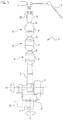
- a tool holding articulated arm according to an embodiment of the present invention will be explained with reference to Figs. 1 to 10 .
- Figure 1 illustrates the tool holding articulated arm 1 according to the embodiment.
- the arm 1 is in an upright state and has a securing part 2 that is at a lower end of the arm 1 and is fixed to, for example, a side rail of an operating table in a hospital.
- the tool holding articulated arm 1 is horizontally rotatable around a vertical axis V and vertically rotatable around a horizontal axis H.
- a clutch C is arranged to fix the arm 1 at an optional rotation angle around the axis.
- a counterweight W is also arranged on the horizontal axis H that extends along the securing part 2.
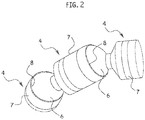
- the tool holding articulated arm 1 includes a base arm 3 at a proximal side thereof, three joints as articulations 4 connected in series, and a front tool holder 5 at a distal side thereof.
- the tool holder 5 holds a medical tool such as an endoscope T.
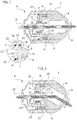
- the articulations 4 each has the same structure, and therefore, the structure of one of the articulations 4 will be explained with reference to Fig. 4 .
- the articulation 4 is made of surface-treated aluminum alloy.
- the articulation 4 includes a ball 6 that has a spherical surface and a central through hollow that substantially has a cylindrical shape having a predetermined diameter.
- the ball 6 is contained in a housing 7 that basically has a cylindrical shape having a central through hole.
- a front opening 8 is formed at a front end of the housing 7.
- a base end of the housing 7 is narrowed.
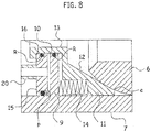
- the front opening 8 of the housing 7 has an inner diameter d that is slightly smaller than a diameter D of the ball 6 as illustrated in Fig. 6 so that a part of the ball 6 may protrude outside from the front opening 8.
- a stopper bottom 9 having a center hole 10 that is provided with a sealing member such as an O-ring R.
- the O-ring R is illustrated as a black circle in the drawings.
- the housing 7 accommodates a presser 11.
- housing 7 is illustrated as a single structure in the drawings, the housing 7 is actually made of a plurality of parts that are assembled into one with the ball 6, presser 11, and the like being incorporated inside the housing 7.
- the presser 11 has a cup shape having a tapered face 12 or a conical frustum inner face.
- a base end of the presser 11 is a cylindrical presser end 13 that is in contact with the O-ring R of the center hole 10 of the stopper bottom 9.
- the presser 11 includes pressing means such as four springs 14 arranged at intervals in a circumferential direction. An end of each spring 14 is in contact with the stopper bottom 9, to bias the presser 11 away from the stopper bottom 9 toward the front end of the housing 7.
- the acting member 15 whose shape is substantially the same as that of the stopper bottom 9.
- the acting member 15 has a center hole 16 where an O-ring R is arranged.
- An outer circumference of the acting member 15 is also provided with an O-ring R, and therefore, the acting member 15 is airtightly in contact with an inner face of the housing 7 and the cylindrical presser end 13, to define a sealed chamber P between the stopper bottom 9 and the acting member 15 as illustrated in Fig. 9 .
- the acting member 15 is coupled with an end of the cylindrical presser end 13 and is movable with the presser 11 in an axial direction.
- the three articulations 4 are connected in series with the proximal end of the housing 7 and the distal end of the ball 6 of the adjacent articulations 4 being connected to each other.
- the ball 6 of the foremost articulation 4 with respect to the base arm 3 is provided with the tool holder 5.
- the tool holder 5 incorporates a valve 17 and is provided with a switch 18 to open and close the valve 17.
- a flexible vinyl double pipe 19 is passed through the base arm 3, three articulations 4, and tool holder 5.
- the double pipe 19 is extended from an air pump (not illustrated) to the valve 17 of the tool holder 5.
- the double pipe 19 includes an inner passage a and an outer passage b that run in parallel with each other as illustrated in Fig. 10 and are connected to each other through the valve 17 as illustrated in Fig. 3 .
- the air pump always supplies compressed air into the inner passage a of the double pipe 19.
- the valve 17 opens to guide the compressed air from the inner passage a into the outer passage b. Namely, the compressed air oppositely flows in the inner passage a and outer passage b.
- a part of the outer passage b is branched into a branch passage 20, which is connected to the sealed chamber P.
- the spring 14 as an elastic element, acting member 15, and sealed chamber P form the pressing mechanism stipulated in the claims.
- the ball 6 is strongly fixed by frictional force between the presser 11 and the front opening 8 of the housing 7. Namely, the balls 6 of the three articulations 4 no longer rotate, and therefore, the articulations 4 keep the fixed states .
- This configuration of holding the ball 6 between the presser 11 and the front opening 8 of the housing 7 creates a strong fixing force at each articulation 4 even with a small operating force of each spring 14.
- the switch 18 of the tool holder 5 is pushed.
- the valve 17 is open to pass compressed air from the inner passage a to the outer passage b of the double pipe 19. From the outer passage b through the branch passages 20, the compressed air is supplied into the sealed chambers P of the articulations 4.
- the supply of compressed air into the double pipe 19 may be adjusted so that proper friction is maintained between the presser 11 and the ball 6 at each articulation 4 when flexing the tool holding articulated arm 1, instead of creating the clear gap S in each articulation 4 as illustrated in Fig. 9 .
- the switch 18 is released. This results in reducing pressure in the sealed chambers P, and therefore, the springs 14 push the pressers 11, which again push the balls 6 to fix the articulations 4 in states when the switch 18 has been released.
- the double pipe 19 alone realizes two opposing flows of compressed air in the tool holding articulated arm 1.
- This configuration reduces the number of pipes in the arm 1 and simplifies the internal structure of each articulation 4.
- the articulations 4 are normally stationary with the bias of the springs 14, and only when required, are released from the stationary state with the use of compressed air supplied from a pump. This configuration is able to keep the articulations 4 immobile even if a contingency such as a blackout occurs.
- the tool holding articulated arm holds the ball between the presser and the front opening of the housing in each joint of the arm.
- This aspect is able to apply a large fixing force to each joint with a small operating force of the presser.
- the tool holding articulated arm according to the second aspect of the present invention employs the cup-shaped presser so that the circumferential edge of the presser comes into linear contact with the surface of the ball. This aspect is able to exert a strong fixing force from the presser onto the surface of the ball.
- the tool holding articulated arm always presses and fixes the pressers to the balls with mechanical pressing force of the springs, and only when required, supplies a gas into the sealed chambers to release the pressing of the pressers on the balls .
- This aspect is able to maintain the fixed state of the joints even if a contingency such as a blackout occurs.
- the tool holding articulated arm according to the fourth aspect of the present invention is capable of fixing and releasing a plurality of the joints with a single piece of the double pipe. This aspect is able to simplify the internal structure of each joint.
Landscapes
- Engineering & Computer Science (AREA)
- Health & Medical Sciences (AREA)
- General Engineering & Computer Science (AREA)
- Life Sciences & Earth Sciences (AREA)
- Surgery (AREA)
- Mechanical Engineering (AREA)
- Animal Behavior & Ethology (AREA)
- Public Health (AREA)
- Nuclear Medicine, Radiotherapy & Molecular Imaging (AREA)
- Veterinary Medicine (AREA)
- Heart & Thoracic Surgery (AREA)
- General Health & Medical Sciences (AREA)
- Medical Informatics (AREA)
- Biomedical Technology (AREA)
- Molecular Biology (AREA)
- Pathology (AREA)
- Robotics (AREA)
- Biophysics (AREA)
- Physics & Mathematics (AREA)
- Radiology & Medical Imaging (AREA)
- Optics & Photonics (AREA)
- Oral & Maxillofacial Surgery (AREA)
- Surgical Instruments (AREA)
- Accommodation For Nursing Or Treatment Tables (AREA)
Claims (2)
- Medizinischer gelenkiger Werkzeughaltearm, mit:mehreren Gelenken (4), die jeweils aufweisen:eine Kugel (6) mit einer Kugeloberfläche;ein Gehäuse (7), das die Kugel (6) aufnimmt und eine vordere Öffnung (8), deren Durchmesser kleiner als der Durchmesser der Kugel ist, und einen Boden mit Haltefunktion (9) gegenüberliegend zu der vorderen Öffnung hat; undeinen Drücker (11), der zwischen dem Boden mit Haltefunktion (9) und der Kugel (6) angeordnet ist und durch einen Drückmechanismus (14, 15, P) zu der Kugel hin und von dieser weg bewegbar ist, wobei die mehreren Gelenke (4) in Reihe mit entsprechenden Enden des Gehäuses (7) und der Kugel (6) der benachbarten Gelenke verbunden sind; undeinem Werkzeughalter (5) zum Halten eines Werkzeugs, das an der Kugel eines vorderen Gelenks der mehreren Gelenke (4) angebracht ist;wobei der Drückmechanismus (14, 15, P) aufweist:eine Feder (14), die zwischen dem Boden mit Haltefunktion (9) und dem Drücker (11) zum Vorspannen des Drückers (11) in Richtung zu der Kugel (6) angeordnet ist;ein Aktivierungselement (15), das mit einem Teil des Drückers (11) hinter dem Boden mit Haltefunktion (9) verbunden ist; undeine abgedichtete Kammer (P), die zwischen dem Aktivierungselement und dem Boden mit Haltefunktion gebildet ist,wobei das Aktivierungselement (15) sich zusammen mit dem Drücker von der Kugel weg bewegt, wenn Gas in die abgedichtete Kammer eingeführt wird;wobei der gelenkige Werkzeughaltearm gekennzeichnet ist durch eine Doppelleitung (19), die flexibel ist und durch die mehreren Gelenke verläuft, wobei die Doppelleitung einen inneren Durchlass (a) und einen äußeren Durchlass (b) aufweist, derart, dassein komprimiertes Gas in dem inneren Durchlass in einer Richtung eingeführt wird, an einem Ende des inneren Durchlasses in den äußeren Durchlass gelenkt und in der entgegengesetzten Richtung durch den äußeren Durchlass geführt wird;ein Ventil (17), das an dem Ende des inneren Durchlasses angeordnet und zum Öffnen und Schließen für das Strömen des komprimierten Gases steuerbar ist; undeinen Verzweigungsdurchlass (20), der von dem äußeren Durchlass in jedem der mehreren Gelenke (4) abzweigt und mit der abgedichteten Kammer (P) verbunden ist.
- Gelenkiger Werkzeughaltearm nach Anspruch 1, dadurch gekennzeichnet, dass der Drücker (11) eine Becherform mit einem Umfangsrand (e) hat, der mit der Oberfläche der Kugel (6) geradlinig in Kontakt gebracht wird.
Applications Claiming Priority (1)
| Application Number | Priority Date | Filing Date | Title |
|---|---|---|---|
| JP2014241106A JP6412783B2 (ja) | 2014-11-28 | 2014-11-28 | 関節式器具保持アーム |
Publications (2)
| Publication Number | Publication Date |
|---|---|
| EP3025668A1 EP3025668A1 (de) | 2016-06-01 |
| EP3025668B1 true EP3025668B1 (de) | 2017-08-30 |
Family
ID=54478635
Family Applications (1)
| Application Number | Title | Priority Date | Filing Date |
|---|---|---|---|
| EP15193677.0A Not-in-force EP3025668B1 (de) | 2014-11-28 | 2015-11-09 | Gelenkiger werkzeughaltearm |
Country Status (3)
| Country | Link |
|---|---|
| US (1) | US20160151920A1 (de) |
| EP (1) | EP3025668B1 (de) |
| JP (1) | JP6412783B2 (de) |
Families Citing this family (20)
| Publication number | Priority date | Publication date | Assignee | Title |
|---|---|---|---|---|
| KR101469539B1 (ko) * | 2014-03-03 | 2014-12-05 | 김석환 | 관절장치 및 이를 적용한 수련구, 링형 관절구조물, 조립완구, 인공관절 |
| US20180111275A1 (en) * | 2014-08-01 | 2018-04-26 | Kugar Inc. | Modular system for constructing robots |
| DK178308B1 (en) * | 2014-12-15 | 2015-11-23 | Ergonomic Solutions Internat Ltd | Modular rotatable link |
| DK179000B1 (en) * | 2015-07-08 | 2017-07-31 | Ergonomic Solutions Int Ltd | Rotatable link |
| AU2018329468B2 (en) * | 2017-09-05 | 2024-05-16 | Medos International Sàrl | Proximal-end securement of a minimally invasive working channel |
| DE102017120771B4 (de) * | 2017-09-08 | 2020-06-04 | Otto-Von-Guericke-Universität Magdeburg | Flexible Haltevorrichtung |
| US11318626B1 (en) * | 2018-03-02 | 2022-05-03 | Empower Robotics Corporation | Compliant joint for a robotic arm |
| US11027438B2 (en) * | 2018-07-13 | 2021-06-08 | A-Dec, Inc. | Positive positioning device and system |
| CN108789484B (zh) * | 2018-08-14 | 2023-10-03 | 芜湖星电自动化科技有限公司 | 医疗机器人手臂连接结构 |
| US11524415B2 (en) * | 2019-04-03 | 2022-12-13 | Swivel-Link, LLC | Boom arm for positioning an auxiliary electrical device |
| CN110507427A (zh) * | 2019-09-02 | 2019-11-29 | 王兴国 | 一种蛇形机械固定臂 |
| CN110693546B (zh) * | 2019-09-11 | 2023-07-21 | 丁起武 | 一种球头压力锁定装置及具有球头压力锁定装置的医学支架 |
| CN110788881B (zh) * | 2019-11-13 | 2022-08-16 | 上海交通大学 | 真空吸附式锁定关节的气动软体抓手 |
| WO2021139145A1 (zh) * | 2020-01-07 | 2021-07-15 | 北京可以科技有限公司 | 一种机械臂装置 |
| WO2022039296A1 (ko) * | 2020-08-19 | 2022-02-24 | 고무생 | 치료 보조 기구 |
| US11745363B1 (en) * | 2021-02-26 | 2023-09-05 | The United States Of America, As Represented By The Secretary Of The Navy | Compact self-centering compliant joint |
| CN113183140B (zh) * | 2021-06-03 | 2021-09-17 | 西南交通大学 | 一种可换挡连接的仿生蛇形机器人及控制系统 |
| CN113370259B (zh) * | 2021-06-04 | 2023-01-20 | 青岛海泰新光科技股份有限公司 | 一种流体锁紧机械臂 |
| CN113616344B (zh) * | 2021-09-13 | 2022-07-12 | 西安交通大学医学院第一附属医院 | 泌尿外科用腹腔镜夹持装置 |
| CN114485270A (zh) * | 2021-12-28 | 2022-05-13 | 河南尖兵野战装备制造有限公司 | 战斗携行具 |
Family Cites Families (6)
| Publication number | Priority date | Publication date | Assignee | Title |
|---|---|---|---|---|
| FR2711506B1 (fr) * | 1993-10-21 | 1995-12-29 | Ognier Jean Francois | Dispositif support pour instrument médical ou chirurgical. |
| JP2843507B2 (ja) | 1994-08-09 | 1999-01-06 | 三鷹光器株式会社 | 関節式器具保持アーム |
| DE19526915B4 (de) * | 1995-07-24 | 2004-05-06 | Aesculap Ag & Co. Kg | Haltevorrichtung für chirurgische Zwecke |
| US6767153B1 (en) * | 2003-02-10 | 2004-07-27 | Dana W. Holbrook | Locking positional arm device |
| JP4455088B2 (ja) * | 2004-02-12 | 2010-04-21 | オリンパス株式会社 | 医療機器保持装置 |
| US20070282311A1 (en) * | 2006-06-01 | 2007-12-06 | Scott Christopher P | Multi-joint fixture system |
-
2014
- 2014-11-28 JP JP2014241106A patent/JP6412783B2/ja not_active Expired - Fee Related
-
2015
- 2015-10-28 US US14/925,014 patent/US20160151920A1/en not_active Abandoned
- 2015-11-09 EP EP15193677.0A patent/EP3025668B1/de not_active Not-in-force
Non-Patent Citations (1)
| Title |
|---|
| None * |
Also Published As
| Publication number | Publication date |
|---|---|
| JP6412783B2 (ja) | 2018-10-24 |
| US20160151920A1 (en) | 2016-06-02 |
| EP3025668A1 (de) | 2016-06-01 |
| JP2016101319A (ja) | 2016-06-02 |
Similar Documents
| Publication | Publication Date | Title |
|---|---|---|
| EP3025668A1 (de) | Gelenkiger werkzeughaltearm | |
| JP7094334B2 (ja) | エンドエフェクタおよびエンドエフェクタドライブ装置 | |
| JP5497186B2 (ja) | 手動操作医療装置を保持するための保持装置 | |
| JP3392813B2 (ja) | 二方弁 | |
| US5464007A (en) | Fluid insensitive braking for an endoscope | |
| US20130247919A1 (en) | Positioning apparatus for biomedical use | |
| JP6389882B2 (ja) | 撓み動作伝動装置、内視鏡曲げコントローラ、及び内視鏡 | |
| US10959605B2 (en) | Device for simultaneous fixation of medical instruments and corresponding system | |
| CN103932802B (zh) | 用于快速夹持微创手术器械或设备的气动臂固定装置 | |
| JP5397863B2 (ja) | 親子式内視鏡 | |
| US20200225446A1 (en) | Prism holder of a surgical instrument, and surgical instrument | |
| CN115813317B (zh) | 内窥镜 | |
| US20170065151A1 (en) | Endoscope | |
| CN214434477U (zh) | 插拔限位组件、执行机构及手术机器人 | |
| JP4614273B2 (ja) | 内視鏡支持装置 | |
| CN214342593U (zh) | 动平台、远心操控机构及手术机器人 | |
| JP4455088B2 (ja) | 医療機器保持装置 | |
| CN113740097B (zh) | 一种测试装置 | |
| CN214342594U (zh) | 驱动组件、执行机构及手术机器人 | |
| US11497386B2 (en) | Control element for an endoscopic apparatus, and endoscopic apparatus comprising a control element of this kind | |
| CN113370259A (zh) | 一种流体锁紧机械臂 | |
| CN223299068U (zh) | 一种内窥镜握持装置 | |
| CN214434476U (zh) | 插拔限位组件、执行机构及手术机器人 | |
| JPWO2015064151A1 (ja) | 内視鏡用処置具及び内視鏡システム | |
| JPH0532815Y2 (de) |
Legal Events
| Date | Code | Title | Description |
|---|---|---|---|
| PUAI | Public reference made under article 153(3) epc to a published international application that has entered the european phase |
Free format text: ORIGINAL CODE: 0009012 |
|
| 17P | Request for examination filed |
Effective date: 20151109 |
|
| AK | Designated contracting states |
Kind code of ref document: A1 Designated state(s): AL AT BE BG CH CY CZ DE DK EE ES FI FR GB GR HR HU IE IS IT LI LT LU LV MC MK MT NL NO PL PT RO RS SE SI SK SM TR |
|
| AX | Request for extension of the european patent |
Extension state: BA ME |
|
| R17P | Request for examination filed (corrected) |
Effective date: 20151109 |
|
| GRAP | Despatch of communication of intention to grant a patent |
Free format text: ORIGINAL CODE: EPIDOSNIGR1 |
|
| RIC1 | Information provided on ipc code assigned before grant |
Ipc: F16C 11/06 20060101ALI20170228BHEP Ipc: A61B 90/50 20160101ALI20170228BHEP Ipc: A61B 50/20 20160101AFI20170228BHEP Ipc: A61B 17/00 20060101ALN20170228BHEP Ipc: F16C 11/10 20060101ALI20170228BHEP Ipc: A61B 90/11 20160101ALI20170228BHEP Ipc: F16C 39/04 20060101ALI20170228BHEP |
|
| RIC1 | Information provided on ipc code assigned before grant |
Ipc: A61B 50/20 20160101AFI20170306BHEP Ipc: A61B 90/11 20160101ALI20170306BHEP Ipc: A61B 17/00 20060101ALN20170306BHEP Ipc: A61B 90/50 20160101ALI20170306BHEP Ipc: F16C 39/04 20060101ALI20170306BHEP Ipc: F16C 11/10 20060101ALI20170306BHEP Ipc: F16C 11/06 20060101ALI20170306BHEP |
|
| INTG | Intention to grant announced |
Effective date: 20170322 |
|
| RIN1 | Information on inventor provided before grant (corrected) |
Inventor name: NAKATA, YUSUKE |
|
| GRAS | Grant fee paid |
Free format text: ORIGINAL CODE: EPIDOSNIGR3 |
|
| GRAA | (expected) grant |
Free format text: ORIGINAL CODE: 0009210 |
|
| AK | Designated contracting states |
Kind code of ref document: B1 Designated state(s): AL AT BE BG CH CY CZ DE DK EE ES FI FR GB GR HR HU IE IS IT LI LT LU LV MC MK MT NL NO PL PT RO RS SE SI SK SM TR |
|
| REG | Reference to a national code |
Ref country code: GB Ref legal event code: FG4D |
|
| REG | Reference to a national code |
Ref country code: CH Ref legal event code: EP |
|
| REG | Reference to a national code |
Ref country code: AT Ref legal event code: REF Ref document number: 922794 Country of ref document: AT Kind code of ref document: T Effective date: 20170915 |
|
| REG | Reference to a national code |
Ref country code: IE Ref legal event code: FG4D |
|
| REG | Reference to a national code |
Ref country code: DE Ref legal event code: R096 Ref document number: 602015004435 Country of ref document: DE |
|
| REG | Reference to a national code |
Ref country code: NL Ref legal event code: MP Effective date: 20170830 |
|
| REG | Reference to a national code |
Ref country code: LT Ref legal event code: MG4D |
|
| REG | Reference to a national code |
Ref country code: AT Ref legal event code: MK05 Ref document number: 922794 Country of ref document: AT Kind code of ref document: T Effective date: 20170830 |
|
| PG25 | Lapsed in a contracting state [announced via postgrant information from national office to epo] |
Ref country code: LT Free format text: LAPSE BECAUSE OF FAILURE TO SUBMIT A TRANSLATION OF THE DESCRIPTION OR TO PAY THE FEE WITHIN THE PRESCRIBED TIME-LIMIT Effective date: 20170830 Ref country code: FI Free format text: LAPSE BECAUSE OF FAILURE TO SUBMIT A TRANSLATION OF THE DESCRIPTION OR TO PAY THE FEE WITHIN THE PRESCRIBED TIME-LIMIT Effective date: 20170830 Ref country code: AT Free format text: LAPSE BECAUSE OF FAILURE TO SUBMIT A TRANSLATION OF THE DESCRIPTION OR TO PAY THE FEE WITHIN THE PRESCRIBED TIME-LIMIT Effective date: 20170830 Ref country code: SE Free format text: LAPSE BECAUSE OF FAILURE TO SUBMIT A TRANSLATION OF THE DESCRIPTION OR TO PAY THE FEE WITHIN THE PRESCRIBED TIME-LIMIT Effective date: 20170830 Ref country code: NO Free format text: LAPSE BECAUSE OF FAILURE TO SUBMIT A TRANSLATION OF THE DESCRIPTION OR TO PAY THE FEE WITHIN THE PRESCRIBED TIME-LIMIT Effective date: 20171130 Ref country code: HR Free format text: LAPSE BECAUSE OF FAILURE TO SUBMIT A TRANSLATION OF THE DESCRIPTION OR TO PAY THE FEE WITHIN THE PRESCRIBED TIME-LIMIT Effective date: 20170830 |
|
| PG25 | Lapsed in a contracting state [announced via postgrant information from national office to epo] |
Ref country code: ES Free format text: LAPSE BECAUSE OF FAILURE TO SUBMIT A TRANSLATION OF THE DESCRIPTION OR TO PAY THE FEE WITHIN THE PRESCRIBED TIME-LIMIT Effective date: 20170830 Ref country code: RS Free format text: LAPSE BECAUSE OF FAILURE TO SUBMIT A TRANSLATION OF THE DESCRIPTION OR TO PAY THE FEE WITHIN THE PRESCRIBED TIME-LIMIT Effective date: 20170830 Ref country code: LV Free format text: LAPSE BECAUSE OF FAILURE TO SUBMIT A TRANSLATION OF THE DESCRIPTION OR TO PAY THE FEE WITHIN THE PRESCRIBED TIME-LIMIT Effective date: 20170830 Ref country code: BG Free format text: LAPSE BECAUSE OF FAILURE TO SUBMIT A TRANSLATION OF THE DESCRIPTION OR TO PAY THE FEE WITHIN THE PRESCRIBED TIME-LIMIT Effective date: 20171130 Ref country code: IS Free format text: LAPSE BECAUSE OF FAILURE TO SUBMIT A TRANSLATION OF THE DESCRIPTION OR TO PAY THE FEE WITHIN THE PRESCRIBED TIME-LIMIT Effective date: 20171230 Ref country code: GR Free format text: LAPSE BECAUSE OF FAILURE TO SUBMIT A TRANSLATION OF THE DESCRIPTION OR TO PAY THE FEE WITHIN THE PRESCRIBED TIME-LIMIT Effective date: 20171201 |
|
| PG25 | Lapsed in a contracting state [announced via postgrant information from national office to epo] |
Ref country code: NL Free format text: LAPSE BECAUSE OF FAILURE TO SUBMIT A TRANSLATION OF THE DESCRIPTION OR TO PAY THE FEE WITHIN THE PRESCRIBED TIME-LIMIT Effective date: 20170830 |
|
| PG25 | Lapsed in a contracting state [announced via postgrant information from national office to epo] |
Ref country code: CZ Free format text: LAPSE BECAUSE OF FAILURE TO SUBMIT A TRANSLATION OF THE DESCRIPTION OR TO PAY THE FEE WITHIN THE PRESCRIBED TIME-LIMIT Effective date: 20170830 Ref country code: PL Free format text: LAPSE BECAUSE OF FAILURE TO SUBMIT A TRANSLATION OF THE DESCRIPTION OR TO PAY THE FEE WITHIN THE PRESCRIBED TIME-LIMIT Effective date: 20170830 Ref country code: RO Free format text: LAPSE BECAUSE OF FAILURE TO SUBMIT A TRANSLATION OF THE DESCRIPTION OR TO PAY THE FEE WITHIN THE PRESCRIBED TIME-LIMIT Effective date: 20170830 Ref country code: DK Free format text: LAPSE BECAUSE OF FAILURE TO SUBMIT A TRANSLATION OF THE DESCRIPTION OR TO PAY THE FEE WITHIN THE PRESCRIBED TIME-LIMIT Effective date: 20170830 |
|
| PG25 | Lapsed in a contracting state [announced via postgrant information from national office to epo] |
Ref country code: SK Free format text: LAPSE BECAUSE OF FAILURE TO SUBMIT A TRANSLATION OF THE DESCRIPTION OR TO PAY THE FEE WITHIN THE PRESCRIBED TIME-LIMIT Effective date: 20170830 Ref country code: EE Free format text: LAPSE BECAUSE OF FAILURE TO SUBMIT A TRANSLATION OF THE DESCRIPTION OR TO PAY THE FEE WITHIN THE PRESCRIBED TIME-LIMIT Effective date: 20170830 Ref country code: SM Free format text: LAPSE BECAUSE OF FAILURE TO SUBMIT A TRANSLATION OF THE DESCRIPTION OR TO PAY THE FEE WITHIN THE PRESCRIBED TIME-LIMIT Effective date: 20170830 Ref country code: IT Free format text: LAPSE BECAUSE OF FAILURE TO SUBMIT A TRANSLATION OF THE DESCRIPTION OR TO PAY THE FEE WITHIN THE PRESCRIBED TIME-LIMIT Effective date: 20170830 |
|
| REG | Reference to a national code |
Ref country code: DE Ref legal event code: R097 Ref document number: 602015004435 Country of ref document: DE |
|
| PG25 | Lapsed in a contracting state [announced via postgrant information from national office to epo] |
Ref country code: MC Free format text: LAPSE BECAUSE OF FAILURE TO SUBMIT A TRANSLATION OF THE DESCRIPTION OR TO PAY THE FEE WITHIN THE PRESCRIBED TIME-LIMIT Effective date: 20170830 |
|
| PLBE | No opposition filed within time limit |
Free format text: ORIGINAL CODE: 0009261 |
|
| STAA | Information on the status of an ep patent application or granted ep patent |
Free format text: STATUS: NO OPPOSITION FILED WITHIN TIME LIMIT |
|
| 26N | No opposition filed |
Effective date: 20180531 |
|
| PG25 | Lapsed in a contracting state [announced via postgrant information from national office to epo] |
Ref country code: LU Free format text: LAPSE BECAUSE OF NON-PAYMENT OF DUE FEES Effective date: 20171109 Ref country code: SI Free format text: LAPSE BECAUSE OF FAILURE TO SUBMIT A TRANSLATION OF THE DESCRIPTION OR TO PAY THE FEE WITHIN THE PRESCRIBED TIME-LIMIT Effective date: 20170830 |
|
| REG | Reference to a national code |
Ref country code: FR Ref legal event code: ST Effective date: 20180731 Ref country code: BE Ref legal event code: MM Effective date: 20171130 |
|
| REG | Reference to a national code |
Ref country code: IE Ref legal event code: MM4A |
|
| PG25 | Lapsed in a contracting state [announced via postgrant information from national office to epo] |
Ref country code: MT Free format text: LAPSE BECAUSE OF NON-PAYMENT OF DUE FEES Effective date: 20171109 |
|
| PG25 | Lapsed in a contracting state [announced via postgrant information from national office to epo] |
Ref country code: IE Free format text: LAPSE BECAUSE OF NON-PAYMENT OF DUE FEES Effective date: 20171109 Ref country code: FR Free format text: LAPSE BECAUSE OF NON-PAYMENT OF DUE FEES Effective date: 20171130 |
|
| PG25 | Lapsed in a contracting state [announced via postgrant information from national office to epo] |
Ref country code: BE Free format text: LAPSE BECAUSE OF NON-PAYMENT OF DUE FEES Effective date: 20171130 |
|
| PG25 | Lapsed in a contracting state [announced via postgrant information from national office to epo] |
Ref country code: HU Free format text: LAPSE BECAUSE OF FAILURE TO SUBMIT A TRANSLATION OF THE DESCRIPTION OR TO PAY THE FEE WITHIN THE PRESCRIBED TIME-LIMIT; INVALID AB INITIO Effective date: 20151109 |
|
| REG | Reference to a national code |
Ref country code: CH Ref legal event code: PL |
|
| PG25 | Lapsed in a contracting state [announced via postgrant information from national office to epo] |
Ref country code: LI Free format text: LAPSE BECAUSE OF NON-PAYMENT OF DUE FEES Effective date: 20181130 Ref country code: CH Free format text: LAPSE BECAUSE OF NON-PAYMENT OF DUE FEES Effective date: 20181130 |
|
| PG25 | Lapsed in a contracting state [announced via postgrant information from national office to epo] |
Ref country code: CY Free format text: LAPSE BECAUSE OF FAILURE TO SUBMIT A TRANSLATION OF THE DESCRIPTION OR TO PAY THE FEE WITHIN THE PRESCRIBED TIME-LIMIT Effective date: 20170830 |
|
| PG25 | Lapsed in a contracting state [announced via postgrant information from national office to epo] |
Ref country code: MK Free format text: LAPSE BECAUSE OF FAILURE TO SUBMIT A TRANSLATION OF THE DESCRIPTION OR TO PAY THE FEE WITHIN THE PRESCRIBED TIME-LIMIT Effective date: 20170830 |
|
| PG25 | Lapsed in a contracting state [announced via postgrant information from national office to epo] |
Ref country code: TR Free format text: LAPSE BECAUSE OF FAILURE TO SUBMIT A TRANSLATION OF THE DESCRIPTION OR TO PAY THE FEE WITHIN THE PRESCRIBED TIME-LIMIT Effective date: 20170830 |
|
| PG25 | Lapsed in a contracting state [announced via postgrant information from national office to epo] |
Ref country code: PT Free format text: LAPSE BECAUSE OF FAILURE TO SUBMIT A TRANSLATION OF THE DESCRIPTION OR TO PAY THE FEE WITHIN THE PRESCRIBED TIME-LIMIT Effective date: 20170830 |
|
| PG25 | Lapsed in a contracting state [announced via postgrant information from national office to epo] |
Ref country code: AL Free format text: LAPSE BECAUSE OF FAILURE TO SUBMIT A TRANSLATION OF THE DESCRIPTION OR TO PAY THE FEE WITHIN THE PRESCRIBED TIME-LIMIT Effective date: 20170830 |
|
| GBPC | Gb: european patent ceased through non-payment of renewal fee |
Effective date: 20191109 |
|
| PG25 | Lapsed in a contracting state [announced via postgrant information from national office to epo] |
Ref country code: GB Free format text: LAPSE BECAUSE OF NON-PAYMENT OF DUE FEES Effective date: 20191109 |
|
| PGFP | Annual fee paid to national office [announced via postgrant information from national office to epo] |
Ref country code: DE Payment date: 20220620 Year of fee payment: 8 |
|
| REG | Reference to a national code |
Ref country code: DE Ref legal event code: R119 Ref document number: 602015004435 Country of ref document: DE |
|
| PG25 | Lapsed in a contracting state [announced via postgrant information from national office to epo] |
Ref country code: DE Free format text: LAPSE BECAUSE OF NON-PAYMENT OF DUE FEES Effective date: 20240601 |
|
| PG25 | Lapsed in a contracting state [announced via postgrant information from national office to epo] |
Ref country code: DE Free format text: LAPSE BECAUSE OF NON-PAYMENT OF DUE FEES Effective date: 20240601 |