EP3025757A1 - Appareil actif implantable pour mrt et capteur mrt - Google Patents
Appareil actif implantable pour mrt et capteur mrt Download PDFInfo
- Publication number
- EP3025757A1 EP3025757A1 EP15190504.9A EP15190504A EP3025757A1 EP 3025757 A1 EP3025757 A1 EP 3025757A1 EP 15190504 A EP15190504 A EP 15190504A EP 3025757 A1 EP3025757 A1 EP 3025757A1
- Authority
- EP
- European Patent Office
- Prior art keywords
- mri
- environment
- electronic device
- implantable electronic
- unit
- Prior art date
- Legal status (The legal status is an assumption and is not a legal conclusion. Google has not performed a legal analysis and makes no representation as to the accuracy of the status listed.)
- Granted
Links
Images

Classifications
-
- A—HUMAN NECESSITIES
- A61—MEDICAL OR VETERINARY SCIENCE; HYGIENE
- A61N—ELECTROTHERAPY; MAGNETOTHERAPY; RADIATION THERAPY; ULTRASOUND THERAPY
- A61N1/00—Electrotherapy; Circuits therefor
- A61N1/18—Applying electric currents by contact electrodes
- A61N1/32—Applying electric currents by contact electrodes alternating or intermittent currents
- A61N1/36—Applying electric currents by contact electrodes alternating or intermittent currents for stimulation
- A61N1/362—Heart stimulators
- A61N1/37—Monitoring; Protecting
- A61N1/3718—Monitoring of or protection against external electromagnetic fields or currents
-
- A—HUMAN NECESSITIES
- A61—MEDICAL OR VETERINARY SCIENCE; HYGIENE
- A61N—ELECTROTHERAPY; MAGNETOTHERAPY; RADIATION THERAPY; ULTRASOUND THERAPY
- A61N1/00—Electrotherapy; Circuits therefor
- A61N1/18—Applying electric currents by contact electrodes
- A61N1/32—Applying electric currents by contact electrodes alternating or intermittent currents
- A61N1/36—Applying electric currents by contact electrodes alternating or intermittent currents for stimulation
- A61N1/3605—Implantable neurostimulators for stimulating central or peripheral nerve system
- A61N1/36128—Control systems
- A61N1/36142—Control systems for improving safety
-
- A—HUMAN NECESSITIES
- A61—MEDICAL OR VETERINARY SCIENCE; HYGIENE
- A61N—ELECTROTHERAPY; MAGNETOTHERAPY; RADIATION THERAPY; ULTRASOUND THERAPY
- A61N1/00—Electrotherapy; Circuits therefor
- A61N1/18—Applying electric currents by contact electrodes
- A61N1/32—Applying electric currents by contact electrodes alternating or intermittent currents
- A61N1/38—Applying electric currents by contact electrodes alternating or intermittent currents for producing shock effects
- A61N1/39—Heart defibrillators
- A61N1/3925—Monitoring; Protecting
- A61N1/3931—Protecting, e.g. back-up systems
-
- A—HUMAN NECESSITIES
- A61—MEDICAL OR VETERINARY SCIENCE; HYGIENE
- A61N—ELECTROTHERAPY; MAGNETOTHERAPY; RADIATION THERAPY; ULTRASOUND THERAPY
- A61N1/00—Electrotherapy; Circuits therefor
- A61N1/18—Applying electric currents by contact electrodes
- A61N1/32—Applying electric currents by contact electrodes alternating or intermittent currents
- A61N1/38—Applying electric currents by contact electrodes alternating or intermittent currents for producing shock effects
- A61N1/39—Heart defibrillators
- A61N1/3925—Monitoring; Protecting
Definitions
- the invention relates to an MRI sensor for an implantable electronic device, which is able to detect when the implantable electronic device is operated within or in the immediate vicinity of an MRI device (magnetic resonance tomograph). Moreover, the invention relates to an MRI-compatible implantable electronic device, in particular an implantable cardiac therapy and / or cardiac monitoring device, such as a pacemaker or cardioverter / defibrillator, with an MRI sensor.
- an MRI-compatible implantable electronic device in particular an implantable cardiac therapy and / or cardiac monitoring device, such as a pacemaker or cardioverter / defibrillator, with an MRI sensor.
- Implantable cardiac therapy and / or cardiac monitoring devices e.g.
- cardiac stimulators in the form of cardiac pacemakers or cardioverters / defibrillators are known in principle.
- Such cardiac stimulators are typically connected to electrode leads that have pacing and, optionally, additional defibrillation electrodes in a chamber of a heart or in its immediate vicinity.
- a stimulation electrode - more precisely one or more stimulation electrode poles - a pacemaker can deliver an electrical stimulation pulse to the muscle tissue of a heart chamber so as to induce a stimulated contraction of the ventricle, provided that the stimulation pulse has sufficient intensity and the myocardial tissue (myocardium) is not in a refractory phase.
- Such a stimulated contraction of a heart chamber is referred to in this specification as a stimulated event
- a stimulation pulse having a sufficient intensity to cause a stimulated contraction of a heart chamber is referred to as "suprathreshold”.
- a natural contraction of the heart chamber this is referred to in the context of this description as a private action or as a natural or intrinsic event.
- a contraction, for example of the right atrium of a heart is referred to as an atrial event, which, for example, is a natural atrial Event, or, in the case of an atrial pacemaker, also a stimulated atrial event.
- natural (intrinsic) and stimulated left ventricular and right ventricular events can be distinguished.
- a local arousal of the myocardium spreads from the excitation site via stimulation in the myocardium and leads to a depolarization of the muscle cells and thus to a contraction of the myocardium. After a short time a repolarization of the muscle cells occurs and thus a relaxation of the myocardium. During the phase of depolarization, the myocardial cells are insensitive to arousal, i. refractory. This time is called the refractory period.
- the electrical potentials associated with depolarization and repolarization can be perceived and their time course - referred to as the electrocardiogram - evaluated.
- action potentials associated with a contraction of the ventricle and reflecting a depolarization of the heart muscle cells can be recognized as a so-called Q-wave, while the repolarization of the heart muscle cells associated with the relaxation of the myocardium is reflected in a so-called T-wave.
- the respective heart rhythm is determined by the sinus node controlled by the autonomic nervous system. This stimulates the right atrium of a human heart by stimulation, and continues via the AV node to the (right) ventricle of the heart.
- a natural heart rhythm emanating from the sinus node is therefore also called sinus rhythm and leads to natural contractions of the respective heart chamber, which can be detected as natural (intrinsic) events.
- the detection of such natural (intrinsic) events is carried out by deriving the electrical potentials of the myocardium of the respective heart chamber by means of sensing electrodes, which are part of a corresponding electrode line.
- the sense electrode poles can simultaneously be the stimulation electrode poles and used alternately as a stimulation pole and as a sense electrode pole become.
- a sense electrode pole pair is provided, which is formed by two adjacent electrode poles, namely a tip electrode (tip electrode) and a ring electrode, of which the tip electrode also serves as stimulation electrode pole.
- IEGM intracardiac electrocardiogram
- a ventricular lead The perception of intrinsic events and the stimulation in the ventricle by means of a ventricular lead and the stimulation and the perception of intrinsic events in the atrium (in the right atrium) with an atrial electrode lead, which are connected separately to the respective heart stimulator.
- a left ventricular electrode lead may also be provided, which typically projects beyond the coronary sinus and a lateral vein branching off from it into the vicinity of the left ventricle and may have a small-area stimulation and / or sensing electrode there.
- implantable cardiac stimulators can be operated in different modes of operation.
- I inhibited
- T triggered
- D both inhibited and triggered
- Atrial pacemakers In the absence of a healthy, natural heart rate in the atrium, for example in the case of atrial tachycardia or atrial fibrillation, atrial pacemakers generally have a mode switching from atrial-synchronous ventricular pacing to atrial-asynchronous pacing in VVI mode if a perceived atrial rate is outside permissible limits. Furthermore, it is known to treat ventricular tachycardias as part of a cardioversion therapy by stimulation with a stimulation rate that is above the tachycardia rate.
- the stimulation modes can be controlled by appropriate control programs, the z. For example, process or ignore captured events, or set by control parameters.
- a control parameter can be used to activate or deactivate the detection of events in the atrium and / or ventricle.
- stimulation or sensing electrode means a respective electrode pole on an electrode lead, that is, that part of an electrode lead via which stimulation pulses are delivered or electrical potentials are picked up. It should also be noted that it is also common to refer to a stimulation electrode serving as a stimulation electrode lead.
- the sensing electrode poles in operation of the cardiac stimulator, are connected to respective sensing units configured to evaluate a respective electrocardiogram acquired via a sensing electrode pole (or sense electrode pole pair) and, in particular, to detect intrinsic atrial or ventricular events, i. natural atrial or ventricular contractions. This is done, for example, by a threshold comparison, i. An intrinsic event is detected when a respective intracardiac electrocardiogram exceeds a threshold value that is considered appropriate.
- the respective intrinsic atrial heart rate (atrial frequency) or ventricular heart rate (ventricular frequency) can be derived and thus, for example, tachycardias can be detected.
- a heart stimulator may be equipped with one or more activity sensors, which may be, for example, a CLS sensor (CLS: Closed Loop Stimulation).
- implantable electrical medical devices such as cardiac stimulators by strong electromagnetic fields or magnetic fields, such as those that occur in a magnetic resonance imaging (MRI), for example, can be severely impaired in their function. Therefore, many wearers of active implantable medical devices (hereafter referred to as implant or IMD) are contraindicated for MRI scans, although MR scans are gaining more and more importance in diagnostic medicine.
- MRI magnetic resonance imaging
- MRT sensors are known, in particular magnetic field sensors, gradient field sensors, high-frequency field sensors, position sensors, noise or (Lorentz) vibration sensors or voltage waveform sensors which monitor characteristic voltage profiles.
- an implantable cardioverter / defibrillator is placed in an operating mode by an cardiologist prior to an MRI scan, which is not affected by the MRI magnetic fields. Following a radiologist's MRI, a cardiologist must return the device to an operating mode that meets the needs of the patient.
- the invention has for its object to provide a supplement or an alternative to known MRT sensors.
- Another aspect is an alternative or supplemented implantable electronic device with an MRI sensor.
- an implantable electronic device having at least one electromagnetic field detection unit which is connected to at least one antenna.
- the field recognition unit is designed to respond to electromagnetic fields that typically occur in the environment of a patient outside the environment of an MRI device and are shielded in the environment of an MRI device.
- the field recognition unit is configured to indicate the absence of such electromagnetic fields that typically occur in the environment of a patient outside the environment of an MRI device and are shielded in the environment of an MRI device.
- the field recognition unit may include at least one receiver tuned to such electromagnetic fields as typically occur in the environment of a patient outside the environment of an MRI apparatus and shielded in the vicinity of an MRI apparatus.
- the field identification unit preferably contains a plurality of such receivers. If none of these receivers indicate a field strength in excess of a given limit field strength in their respective receiving area, a control unit connected to the receiver or receivers signals the absence of such electromagnetic fields that typically occur in the environment of a patient outside the environment of an MRI apparatus and in the The environment of an MRI device are shielded.
- the field recognition unit may also have a tunable receiver as a wideband frequency detection unit for scanning a wider frequency range and be connected to or have a field characteristic memory.
- the field characteristics memory contains characteristic features of electromagnetic fields which occur only outside the environment of an MRI apparatus and are shielded in the environment of an MRI apparatus. Such characteristic features may be, for example, frequencies or frequency ranges of electromagnetic fields.
- the field recognition unit is designed to detect the absence of one or more electromagnetic fields normally present in the patient environment and to display the MRI environment whenever all fields have "disappeared”.
- An MRI sensor makes it possible, by automatically detecting the surroundings of an MRI apparatus, to improve the fitness of an active implantable medical device even under the influence of magnetic fields typical of a magnetic resonance tomograph (MRI).
- MRI magnetic resonance tomograph
- the MRI sensor is part of an electronic implantable device in the form of a heart stimulator, which has a stimulation control unit and a memory unit.
- the memory unit stores program information on control programs and / or control parameters which control the function of the stimulation control unit.
- the stimulation control unit is such a control program or control parameters to allow safe operation of the implantable electronic device in the environment of an MRI device.
- the control programs or control parameters to be selected are, for example, those which set the perception and / or pacing mode to V00 or A00, ie switch off the perception.
- the stimulation control unit is preferably designed to maintain the selected control program or parameters as long as the field recognition unit indicates the absence of electromagnetic fields typically occurring in the environment of a patient outside the environment of an MRI device and shielded in the environment of an MRI device are.
- Control programs or control parameters determine the mode of operation, in particular the respective operating mode of the implantable electronic device, which is typically controlled by the stimulation control unit. In this sense, control programs or control parameters stored in the memory unit affect the operation of the pacing control unit.
- the stimulation control unit controls not only the operation of the implantable electronic device with respect to, for example, a therapy delivery such as cardiac stimulation, but the stimulation control unit also selects a respective applicable control program or applicable control parameters, which in turn then z. B. define the therapy delivery.
- the invention enables the safe operation of an electronic implant in an MRI, without having to re-program or adapt the MRI program immediately before the examination.
- the electronic implantable device is an implantable pulse generator (IPG) and / or an implantable cardioverter / defibrillator (ICD) and / or cardiac resynchronization therapy (CRT) heart stimulator or neurostimulator.
- IPG implantable pulse generator
- ICD implantable cardioverter / defibrillator
- CRT cardiac resynchronization therapy
- the electronic implantable device is particularly preferably a cardiac therapy and / or cardiac monitoring device, in particular an implantable, for example biventricular pacemaker and / or cardioverter / defibrillator.
- a cardiac resynchronization therapy (CRT) can be carried out with a biventricular pacemaker.
- the memory unit includes a control program selectable by the control unit configured to inhibit stimulation pulses from being triggered by this control program.
- the memory unit thus includes at least one program that effects an operating mode that is without stimulation.
- the memory device may also include a control program selectable by the control unit or selectable control parameters configured or configured such that causing the control unit to cause asynchronous pacing in an asynchronous pacing mode such as V00 or D00.
- asynchronous pacing mode such as V00 or D00.
- these pacing modes do not require the sensing of intrinsic events, so there is no inhibition or triggering of pacing pulses by sensed intrinsic events.
- Such stimulation modes take into account the fact that as a result of changing magnetic or electromagnetic fields, a heart stimulator could erroneously detect signals induced by these fields as intrinsic events. In a pure stimulation mode that does not require the detection of intrinsic events, this problem does not exist.
- the memory unit stores a control program that can be selected by the control unit and that is configured to cause asynchronous pacing in an asynchronous pacing mode such as VOO or DOO ,
- Control programs or control parameters to be selected in each case are preferably selected so as to ensure fundamentally safe operation of the implantable electronic device in a magnetic resonance tomograph, for example deactivating the shock delivery in an ICD.
- the MRT sensor additionally has a magnetic field sensor and / or a gradient field sensor and / or a high-frequency field sensor and / or a position sensor and / or a (Lorenz) vibration sensor and / or a voltage profile sensor which monitors characteristic voltage profiles, for example in the electrode lines ,
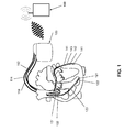
- a cardiac therapy and / or cardiac monitoring device in the form of a three-chamber ICD system is shown.
- This includes a generator 100 (as the cardiac therapy and / or cardiac monitoring device) connected to a plurality of implantable electrode leads 110, 112, and 114.
- a right ventricular (RV) electrode lead 110 is provided which includes a right ventricular (RV) tip electrode 121 and a right ventricular (RV) ring electrode 122 at the distal end.
- a distal shock coil 123 and optionally also a proximal shock coil are attached to this electrode lead 110.
- the counterelectrode here forms the generator housing of the generator 100.
- a right atrial electrode lead 112 has at its distal end a bipolar sensing and pacing pole with a right atrial tip electrode 131 and a right atrial ring electrode 132 for sensing the atrial rhythm and atrial pacing as needed.
- the system also includes a left ventricular CS electrode lead for delivering left ventricular pacing pulses to the CRT via one or more of a total of four left ventricular (CS) stimulation electrode poles 141, 142, 143 and 144.
- CS left ventricular
- a wireless bidirectional telemetry unit is provided in the generator 100.
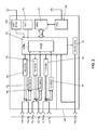
- FIG. 2 shows the major components of the heart stimulator 100 FIG. 1 , On the left side, the electrical connections for the various electrodes 121, 122, 131 and 132 are shown.
- the shock electrodes 123 are connected to a right ventricular shock pulse generator 50.
- the shock pulse generator 50 is connected to a pacing control unit 54 which drives the shock pulse generator 50 to generate and deliver a defibrillation shock as needed.
- the right ventricular tip electrode connector 121 (RV tip) and right ventricular ring electrode connector 122 (RV ring) are each connected to both a right ventricular pacing unit 56 and a right ventricular sensing unit 58. Both the right ventricular pacing unit 56 and the right ventricular sensing unit 58 are each connected to the pacing control unit 54.
- the right-ventricular stimulation unit 56 is designed to generate a right-ventricular stimulation pulse in response to a control signal of the stimulation control unit 54 and subsequently deliver it via the right-ventricular ring electrode 122 (RV ring) and the right-ventricular tip electrode 121 (RV tip).
- the housing of the generator 100 forms a neutral electrode and the right ventricular pacing unit 56 is connected to the right ventricular ring electrode terminal 122 (RV ring) and the housing as another electrode for delivering a pacing pulse.
- a right ventricular stimulation pulse differs from a defibrillation shock in that the stimulation pulse has a much lower pulse strength so that it does not deliver the full heart tissue (myocardium) of a heartbeat (such as a defibrillation shock) But only the heart muscle cells in the immediate vicinity of the right ventricular tip electrode 121 (RV tip). This excitement then spreads through natural conduction across the entire right ventricle and thus provides for a stimulated contraction of the right ventricle.
- the right ventricular sensing unit 58 is configured to first amplify and filter electrical potential applied to the right ventricular ring electrode terminal 122 (RV ring) and right ventricular tip electrode 121 (RV tip) by an input amplifier. Furthermore, the right ventricular perception unit 58 is designed to evaluate the course of the electrical signals present at its inputs in such a way that the right-ventricular perception unit 58 automatically generates a natural (intrinsic), i. automatic, contraction of the right ventricle detected. This can be done, for example, by comparing the course of the signal applied to the inputs of the right-ventricular perception unit 58 with a threshold value.
- the largest amplitude of the so-called R-wave signal is indicative of a natural contraction of the right ventricle, which can be detected by threshold comparison.
- the right ventricular sensing unit 58 then outputs a corresponding output signal indicative of natural contraction of the right ventricle to the pacing control unit 54.
- the time at which the threshold is exceeded is the detection time for the particular event.
- perception units may be provided. These perception units or perception units are preferably designed to detect signals between the shock electrodes, between the shock electrode 123 and the housing of the generator 100 or between the other shock electrode and the housing of the generator 100.
- connection for the right atrial tip electrode 131 (RA Tip) and the connection for the right atrial ring electrode 132 (RA ring) are both with a right atrial stimulation unit 60 and with a right atrial Perception unit 62, each in turn connected to the stimulation control unit 54.
- the right atrial stimulation unit 60 is designed to generate stimulation pulses whose strength is sufficient to excite the right atrial myocardium.
- the right-atrial stimulation pulses may have a different pulse strength than the right-ventricular stimulation pulses.
- the right-atrial perception unit 62 is designed to detect a so-called P-wave from the course of the differential signal present at its inputs, which characterizes a natural (intrinsic) contraction of the right atrium. If the right atrial sensing unit 62 detects a corresponding P-wave, it generates an output signal and passes it on to the stimulation control unit 54, which identifies a natural contraction of the right atrium.
- left ventricular tip electrode terminal 141 (LV tip) and the left ventricular ring electrode terminals 142, 143, and 144 (for convenience, only one LV ring terminal is shown) are provided with a left ventricular pacing unit 64 and a left ventricular pacing unit Connected left ventricular perception unit 66.
- the left ventricular pacing unit 64 and the left ventricular sensing unit 66 are also connected to the pacing control unit 54. Both work similarly to the previously described stimulation units 56 and 60 and perception units 58 and 62.
- an acceleration sensor 72 is connected to the stimulation control unit 54 and integrated into the housing 42 of the heart stimulator 100.
- the acceleration sensor 72 is designed to detect a movement signal dependent on the physical activity of a patient and to output a corresponding first accelerometer output signal, which indicates the physical activity of the patient, to the stimulation control unit 54. This allows the pacing control unit 54 to adjust the timing of the pacing pulses to the needs of the patient (hemodynamic needs).
- the accelerometer output signal can also be used to determine rest periods, in which preferably a dislocation detection can take place.
- the generator 100 comprises a memory unit 80, which is connected to the stimulation control unit 54 and allows signals generated or evaluated by the stimulation control unit 54 to be stored.
- the memory unit 80 allows control programs for the stimulation control unit 54 to be stored in changeable form.
- the stimulation control unit 54 is connected to an MRT sensor 200.
- the MRI sensor 200 comprises a field recognition unit, as associated with FIG. 4 is explained in more detail and may additionally comprise a magnetic field sensor and / or a gradient field sensor and / or a high-frequency field sensor and / or a position sensor and / or a (Lorentz) vibration sensor and / or a voltage waveform sensor.
- the memory unit 80 is connected to a telemetry unit 84, which allows data stored in the memory unit 80 to be wirelessly transmitted to the external device 160 or to transmit programming commands from the external device 160 to the heart stimulator 100 and stored in the memory unit 80.
- the implantable electronic device allows automatic MRI detection and switching to a safe state during an MRI examination, wherein at least two patient-specific MRI program settings are stored in the implantable electronic device, which are detected as a function of the implant before the MRI examination Patient status will be automatically selected.
- FIG. 3 is a typical sequence of an MRI examination of an ICD patient without inventive device shown.
- An ICD patient 300 is followed up by a cardiologist 310 and the ICD is turned off prior to the scheduled MRI scan.
- the MRI examination is performed by a radiologist 320.
- the patient is again cared for by the cardiologist 330 and the ICD is switched on again.
- the entire time beginning with the MRI scan by a radiologist 320 to to the reconnection of the ICD by the cardiologist 330 is the patient without the protection of the implanted defibrillator and largely without rhythm monitoring.
- this residual residual risk measured by the benefit of the MRI scan, is accepted.
- the illustrated sequence can indeed be changed in such a way that now the MRI setting only becomes effective during the MRI examination and the final follow-up by the cardiologist 330 for the reprogramming can be dispensed with.
- the time of the first follow-up by the cardiologist 310 for determining the MRI program can not take place arbitrarily long before the actual MRI examination by the radiologist 320, since the conditions of the patient change and thus an adaptation of the MRI program becomes necessary ,
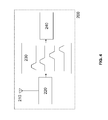
- FIG. 4 a possible block diagram of an MRI sensor 200 of such an electronic implant 100 is shown.
- the MRT sensor 200 includes at least one antenna 210, connected to an antenna matching network / amplifier 220, in turn connected to a tunable, low-power broadband frequency detection unit 230 which cyclically scans the field strengths of the defined ambient frequencies and signals to a control unit 240.
- the control unit 240 compares all of the broadband frequency detection unit 230 received with a field strength above a (predetermined) boundary field strength with previously stored field characteristics, namely in particular previously stored frequency ranges of such ambient frequencies, typically in the environment of the implantable electronic device outside the Environment of an MRI device are present. If this control unit 240 no longer recognizes any of these previously stored ambient frequencies, the control unit 240 signals an MRT environment.
- the broadband frequency detection unit 230 together with the control unit 240 forms a field identification unit.
- Suitable frequencies should be selected from the frequency bands between 30kHz to 30GHz.
Landscapes
- Health & Medical Sciences (AREA)
- Animal Behavior & Ethology (AREA)
- Public Health (AREA)
- Engineering & Computer Science (AREA)
- Biomedical Technology (AREA)
- Nuclear Medicine, Radiotherapy & Molecular Imaging (AREA)
- Radiology & Medical Imaging (AREA)
- Veterinary Medicine (AREA)
- Life Sciences & Earth Sciences (AREA)
- General Health & Medical Sciences (AREA)
- Heart & Thoracic Surgery (AREA)
- Cardiology (AREA)
- Physics & Mathematics (AREA)
- Electromagnetism (AREA)
- Neurology (AREA)
- Neurosurgery (AREA)
- Electrotherapy Devices (AREA)
Applications Claiming Priority (1)
| Application Number | Priority Date | Filing Date | Title |
|---|---|---|---|
| US201462085259P | 2014-11-27 | 2014-11-27 |
Publications (2)
| Publication Number | Publication Date |
|---|---|
| EP3025757A1 true EP3025757A1 (fr) | 2016-06-01 |
| EP3025757B1 EP3025757B1 (fr) | 2017-08-02 |
Family
ID=54337185
Family Applications (1)
| Application Number | Title | Priority Date | Filing Date |
|---|---|---|---|
| EP15190504.9A Active EP3025757B1 (fr) | 2014-11-27 | 2015-10-20 | Appareil actif implantable pour mrt |
Country Status (2)
| Country | Link |
|---|---|
| US (1) | US9694176B2 (fr) |
| EP (1) | EP3025757B1 (fr) |
Families Citing this family (4)
| Publication number | Priority date | Publication date | Assignee | Title |
|---|---|---|---|---|
| US9174058B2 (en) | 2009-09-29 | 2015-11-03 | Medtronic, Inc. | Automatic selection of parameters of an exposure mode of an implantable medical device |
| US10441798B2 (en) | 2016-04-15 | 2019-10-15 | Medtronic, Inc. | Methods and implantable medical systems that implement exposure modes of therapy that allow for continued operation during exposure to a magnetic disturbance |
| US10293167B2 (en) | 2016-04-15 | 2019-05-21 | Medtronic, Inc. | Methods and implantable medical systems that implement exposure modes of therapy that allow for continued operation during exposure to a magnetic disturbance |
| US12447348B2 (en) | 2021-12-15 | 2025-10-21 | Medtronic, Inc. | Secondary verification of MRI exposure at an implantable medical device |
Citations (4)
| Publication number | Priority date | Publication date | Assignee | Title |
|---|---|---|---|---|
| US20080154342A1 (en) | 2006-12-21 | 2008-06-26 | Dennis Digby | Implantable medical device comprising magnetic field detector |
| EP2338560A2 (fr) * | 2009-12-22 | 2011-06-29 | Biotronik CRM Patent AG | Antenne MRT |
| EP2338559A1 (fr) * | 2009-12-22 | 2011-06-29 | BIOTRONIK CRM Patent AG | Détecteur de champ à gradients IRM |
| US20130317345A1 (en) * | 2011-08-19 | 2013-11-28 | Greatbatch Ltd. | Implantable cardioverter defibrillator designed for use in a magnetic resonance imaging environment |
Family Cites Families (2)
| Publication number | Priority date | Publication date | Assignee | Title |
|---|---|---|---|---|
| US7164950B2 (en) * | 2002-10-30 | 2007-01-16 | Pacesetter, Inc. | Implantable stimulation device with isolating system for minimizing magnetic induction |
| US8014867B2 (en) * | 2004-12-17 | 2011-09-06 | Cardiac Pacemakers, Inc. | MRI operation modes for implantable medical devices |
-
2015
- 2015-10-20 EP EP15190504.9A patent/EP3025757B1/fr active Active
- 2015-11-19 US US14/946,398 patent/US9694176B2/en not_active Expired - Fee Related
Patent Citations (4)
| Publication number | Priority date | Publication date | Assignee | Title |
|---|---|---|---|---|
| US20080154342A1 (en) | 2006-12-21 | 2008-06-26 | Dennis Digby | Implantable medical device comprising magnetic field detector |
| EP2338560A2 (fr) * | 2009-12-22 | 2011-06-29 | Biotronik CRM Patent AG | Antenne MRT |
| EP2338559A1 (fr) * | 2009-12-22 | 2011-06-29 | BIOTRONIK CRM Patent AG | Détecteur de champ à gradients IRM |
| US20130317345A1 (en) * | 2011-08-19 | 2013-11-28 | Greatbatch Ltd. | Implantable cardioverter defibrillator designed for use in a magnetic resonance imaging environment |
Also Published As
| Publication number | Publication date |
|---|---|
| EP3025757B1 (fr) | 2017-08-02 |
| US9694176B2 (en) | 2017-07-04 |
| US20160151623A1 (en) | 2016-06-02 |
Similar Documents
| Publication | Publication Date | Title |
|---|---|---|
| DE60222071T2 (de) | Implantierbares Herzschrittmachersystem mit Kalibrierung für automatische Erregungsbestätigung | |
| EP2060299B1 (fr) | Stimulateur cardiaque bi-ventriculaire | |
| DE60122820T2 (de) | Vorrichtung zur Verringerung der Effekte von evozierten Potentialen bei Polarisationsmessungen in einem Herzschrittmachersystem mit automatischer Erfassung des Einfanges | |
| EP3025759A1 (fr) | Appareil implantable actif adapté pour une utilisation avec irm | |
| EP2628503B1 (fr) | Stimulateur cardiaque pour une modulation de la contractilité cardiaque | |
| EP2540341B1 (fr) | Stimulateur cardiaque destiné à administrer un traitement de modulation de la contractilité cardiaque | |
| EP3025757B1 (fr) | Appareil actif implantable pour mrt | |
| EP2676697B1 (fr) | Capteur de dislocation | |
| EP2502646B1 (fr) | Appareil implantable | |
| DE10119387A1 (de) | Verfahren und System zur Bestimmung eines Rauschuntergrundes in einem Herzschrittmachersystem | |
| EP2540342A1 (fr) | Stimulateur cardiaque destiné à administrer un traitement de modulation de la contractilité cardiaque | |
| EP2111892B1 (fr) | Stimulateur cardiaque contre la tachychardie | |
| EP2578268B1 (fr) | Capteur de température pour un appareil médical implantable | |
| EP2140910B1 (fr) | Stimulateur cardiaque destiné au traitement des rythmes tachycardiques | |
| EP2422843B1 (fr) | Appareil de thérapie électronique implantable | |
| EP2135641A1 (fr) | Stimulateur cardiaque contre la tachycardie | |
| EP2111893A1 (fr) | Stimulateur cardiaque ventriculaire | |
| DE60316050T2 (de) | Vorrichtung zur anpassung der sensitivität eines implantierbaren medizinprodukts | |
| EP2826523B1 (fr) | Appareil thérapeutique cardiaque implantable | |
| EP2338561B1 (fr) | Dispositif médical implantable avec un mode bruit prolongé | |
| EP2174688B1 (fr) | Dispositif pour traitement des signaux du coeur | |
| EP2075033B1 (fr) | Stimulateur cardiaque biventriculaire | |
| EP2510975A1 (fr) | Stimulateur cardiaque | |
| EP1578491B1 (fr) | Stimulateur cardiaque implantable | |
| Umrechnungstabelle | Intervalle/Frequenzen |
Legal Events
| Date | Code | Title | Description |
|---|---|---|---|
| PUAI | Public reference made under article 153(3) epc to a published international application that has entered the european phase |
Free format text: ORIGINAL CODE: 0009012 |
|
| AK | Designated contracting states |
Kind code of ref document: A1 Designated state(s): AL AT BE BG CH CY CZ DE DK EE ES FI FR GB GR HR HU IE IS IT LI LT LU LV MC MK MT NL NO PL PT RO RS SE SI SK SM TR |
|
| AX | Request for extension of the european patent |
Extension state: BA ME |
|
| 17P | Request for examination filed |
Effective date: 20161128 |
|
| RBV | Designated contracting states (corrected) |
Designated state(s): AL AT BE BG CH CY CZ DE DK EE ES FI FR GB GR HR HU IE IS IT LI LT LU LV MC MK MT NL NO PL PT RO RS SE SI SK SM TR |
|
| GRAP | Despatch of communication of intention to grant a patent |
Free format text: ORIGINAL CODE: EPIDOSNIGR1 |
|
| INTG | Intention to grant announced |
Effective date: 20170224 |
|
| GRAS | Grant fee paid |
Free format text: ORIGINAL CODE: EPIDOSNIGR3 |
|
| GRAA | (expected) grant |
Free format text: ORIGINAL CODE: 0009210 |
|
| AK | Designated contracting states |
Kind code of ref document: B1 Designated state(s): AL AT BE BG CH CY CZ DE DK EE ES FI FR GB GR HR HU IE IS IT LI LT LU LV MC MK MT NL NO PL PT RO RS SE SI SK SM TR |
|
| REG | Reference to a national code |
Ref country code: CH Ref legal event code: EP Ref country code: AT Ref legal event code: REF Ref document number: 913811 Country of ref document: AT Kind code of ref document: T Effective date: 20170815 |
|
| REG | Reference to a national code |
Ref country code: IE Ref legal event code: FG4D Free format text: LANGUAGE OF EP DOCUMENT: GERMAN |
|
| REG | Reference to a national code |
Ref country code: DE Ref legal event code: R096 Ref document number: 502015001560 Country of ref document: DE |
|
| REG | Reference to a national code |
Ref country code: NL Ref legal event code: MP Effective date: 20170802 |
|
| REG | Reference to a national code |
Ref country code: LT Ref legal event code: MG4D |
|
| PG25 | Lapsed in a contracting state [announced via postgrant information from national office to epo] |
Ref country code: SE Free format text: LAPSE BECAUSE OF FAILURE TO SUBMIT A TRANSLATION OF THE DESCRIPTION OR TO PAY THE FEE WITHIN THE PRESCRIBED TIME-LIMIT Effective date: 20170802 Ref country code: HR Free format text: LAPSE BECAUSE OF FAILURE TO SUBMIT A TRANSLATION OF THE DESCRIPTION OR TO PAY THE FEE WITHIN THE PRESCRIBED TIME-LIMIT Effective date: 20170802 Ref country code: FI Free format text: LAPSE BECAUSE OF FAILURE TO SUBMIT A TRANSLATION OF THE DESCRIPTION OR TO PAY THE FEE WITHIN THE PRESCRIBED TIME-LIMIT Effective date: 20170802 Ref country code: NO Free format text: LAPSE BECAUSE OF FAILURE TO SUBMIT A TRANSLATION OF THE DESCRIPTION OR TO PAY THE FEE WITHIN THE PRESCRIBED TIME-LIMIT Effective date: 20171102 Ref country code: LT Free format text: LAPSE BECAUSE OF FAILURE TO SUBMIT A TRANSLATION OF THE DESCRIPTION OR TO PAY THE FEE WITHIN THE PRESCRIBED TIME-LIMIT Effective date: 20170802 Ref country code: NL Free format text: LAPSE BECAUSE OF FAILURE TO SUBMIT A TRANSLATION OF THE DESCRIPTION OR TO PAY THE FEE WITHIN THE PRESCRIBED TIME-LIMIT Effective date: 20170802 |
|
| PG25 | Lapsed in a contracting state [announced via postgrant information from national office to epo] |
Ref country code: LV Free format text: LAPSE BECAUSE OF FAILURE TO SUBMIT A TRANSLATION OF THE DESCRIPTION OR TO PAY THE FEE WITHIN THE PRESCRIBED TIME-LIMIT Effective date: 20170802 Ref country code: ES Free format text: LAPSE BECAUSE OF FAILURE TO SUBMIT A TRANSLATION OF THE DESCRIPTION OR TO PAY THE FEE WITHIN THE PRESCRIBED TIME-LIMIT Effective date: 20170802 Ref country code: GR Free format text: LAPSE BECAUSE OF FAILURE TO SUBMIT A TRANSLATION OF THE DESCRIPTION OR TO PAY THE FEE WITHIN THE PRESCRIBED TIME-LIMIT Effective date: 20171103 Ref country code: BG Free format text: LAPSE BECAUSE OF FAILURE TO SUBMIT A TRANSLATION OF THE DESCRIPTION OR TO PAY THE FEE WITHIN THE PRESCRIBED TIME-LIMIT Effective date: 20171102 Ref country code: IS Free format text: LAPSE BECAUSE OF FAILURE TO SUBMIT A TRANSLATION OF THE DESCRIPTION OR TO PAY THE FEE WITHIN THE PRESCRIBED TIME-LIMIT Effective date: 20171202 Ref country code: RS Free format text: LAPSE BECAUSE OF FAILURE TO SUBMIT A TRANSLATION OF THE DESCRIPTION OR TO PAY THE FEE WITHIN THE PRESCRIBED TIME-LIMIT Effective date: 20170802 Ref country code: PL Free format text: LAPSE BECAUSE OF FAILURE TO SUBMIT A TRANSLATION OF THE DESCRIPTION OR TO PAY THE FEE WITHIN THE PRESCRIBED TIME-LIMIT Effective date: 20170802 |
|
| PG25 | Lapsed in a contracting state [announced via postgrant information from national office to epo] |
Ref country code: CZ Free format text: LAPSE BECAUSE OF FAILURE TO SUBMIT A TRANSLATION OF THE DESCRIPTION OR TO PAY THE FEE WITHIN THE PRESCRIBED TIME-LIMIT Effective date: 20170802 Ref country code: RO Free format text: LAPSE BECAUSE OF FAILURE TO SUBMIT A TRANSLATION OF THE DESCRIPTION OR TO PAY THE FEE WITHIN THE PRESCRIBED TIME-LIMIT Effective date: 20170802 Ref country code: DK Free format text: LAPSE BECAUSE OF FAILURE TO SUBMIT A TRANSLATION OF THE DESCRIPTION OR TO PAY THE FEE WITHIN THE PRESCRIBED TIME-LIMIT Effective date: 20170802 |
|
| REG | Reference to a national code |
Ref country code: DE Ref legal event code: R097 Ref document number: 502015001560 Country of ref document: DE |
|
| PG25 | Lapsed in a contracting state [announced via postgrant information from national office to epo] |
Ref country code: SK Free format text: LAPSE BECAUSE OF FAILURE TO SUBMIT A TRANSLATION OF THE DESCRIPTION OR TO PAY THE FEE WITHIN THE PRESCRIBED TIME-LIMIT Effective date: 20170802 Ref country code: SM Free format text: LAPSE BECAUSE OF FAILURE TO SUBMIT A TRANSLATION OF THE DESCRIPTION OR TO PAY THE FEE WITHIN THE PRESCRIBED TIME-LIMIT Effective date: 20170802 Ref country code: IT Free format text: LAPSE BECAUSE OF FAILURE TO SUBMIT A TRANSLATION OF THE DESCRIPTION OR TO PAY THE FEE WITHIN THE PRESCRIBED TIME-LIMIT Effective date: 20170802 Ref country code: EE Free format text: LAPSE BECAUSE OF FAILURE TO SUBMIT A TRANSLATION OF THE DESCRIPTION OR TO PAY THE FEE WITHIN THE PRESCRIBED TIME-LIMIT Effective date: 20170802 Ref country code: MC Free format text: LAPSE BECAUSE OF FAILURE TO SUBMIT A TRANSLATION OF THE DESCRIPTION OR TO PAY THE FEE WITHIN THE PRESCRIBED TIME-LIMIT Effective date: 20170802 |
|
| PLBE | No opposition filed within time limit |
Free format text: ORIGINAL CODE: 0009261 |
|
| STAA | Information on the status of an ep patent application or granted ep patent |
Free format text: STATUS: NO OPPOSITION FILED WITHIN TIME LIMIT |
|
| 26N | No opposition filed |
Effective date: 20180503 |
|
| REG | Reference to a national code |
Ref country code: FR Ref legal event code: ST Effective date: 20180629 |
|
| PG25 | Lapsed in a contracting state [announced via postgrant information from national office to epo] |
Ref country code: LU Free format text: LAPSE BECAUSE OF NON-PAYMENT OF DUE FEES Effective date: 20171020 |
|
| REG | Reference to a national code |
Ref country code: BE Ref legal event code: MM Effective date: 20171031 |
|
| PG25 | Lapsed in a contracting state [announced via postgrant information from national office to epo] |
Ref country code: SI Free format text: LAPSE BECAUSE OF FAILURE TO SUBMIT A TRANSLATION OF THE DESCRIPTION OR TO PAY THE FEE WITHIN THE PRESCRIBED TIME-LIMIT Effective date: 20170802 Ref country code: BE Free format text: LAPSE BECAUSE OF NON-PAYMENT OF DUE FEES Effective date: 20171031 Ref country code: FR Free format text: LAPSE BECAUSE OF NON-PAYMENT OF DUE FEES Effective date: 20171031 |
|
| PG25 | Lapsed in a contracting state [announced via postgrant information from national office to epo] |
Ref country code: MT Free format text: LAPSE BECAUSE OF FAILURE TO SUBMIT A TRANSLATION OF THE DESCRIPTION OR TO PAY THE FEE WITHIN THE PRESCRIBED TIME-LIMIT Effective date: 20170802 |
|
| PG25 | Lapsed in a contracting state [announced via postgrant information from national office to epo] |
Ref country code: HU Free format text: LAPSE BECAUSE OF FAILURE TO SUBMIT A TRANSLATION OF THE DESCRIPTION OR TO PAY THE FEE WITHIN THE PRESCRIBED TIME-LIMIT; INVALID AB INITIO Effective date: 20151020 |
|
| PG25 | Lapsed in a contracting state [announced via postgrant information from national office to epo] |
Ref country code: CY Free format text: LAPSE BECAUSE OF FAILURE TO SUBMIT A TRANSLATION OF THE DESCRIPTION OR TO PAY THE FEE WITHIN THE PRESCRIBED TIME-LIMIT Effective date: 20170802 |
|
| PG25 | Lapsed in a contracting state [announced via postgrant information from national office to epo] |
Ref country code: MK Free format text: LAPSE BECAUSE OF FAILURE TO SUBMIT A TRANSLATION OF THE DESCRIPTION OR TO PAY THE FEE WITHIN THE PRESCRIBED TIME-LIMIT Effective date: 20170802 |
|
| PG25 | Lapsed in a contracting state [announced via postgrant information from national office to epo] |
Ref country code: TR Free format text: LAPSE BECAUSE OF FAILURE TO SUBMIT A TRANSLATION OF THE DESCRIPTION OR TO PAY THE FEE WITHIN THE PRESCRIBED TIME-LIMIT Effective date: 20170802 |
|
| PG25 | Lapsed in a contracting state [announced via postgrant information from national office to epo] |
Ref country code: PT Free format text: LAPSE BECAUSE OF FAILURE TO SUBMIT A TRANSLATION OF THE DESCRIPTION OR TO PAY THE FEE WITHIN THE PRESCRIBED TIME-LIMIT Effective date: 20170802 |
|
| PG25 | Lapsed in a contracting state [announced via postgrant information from national office to epo] |
Ref country code: AL Free format text: LAPSE BECAUSE OF FAILURE TO SUBMIT A TRANSLATION OF THE DESCRIPTION OR TO PAY THE FEE WITHIN THE PRESCRIBED TIME-LIMIT Effective date: 20170802 |
|
| GBPC | Gb: european patent ceased through non-payment of renewal fee |
Effective date: 20191020 |
|
| PG25 | Lapsed in a contracting state [announced via postgrant information from national office to epo] |
Ref country code: GB Free format text: LAPSE BECAUSE OF NON-PAYMENT OF DUE FEES Effective date: 20191020 |
|
| REG | Reference to a national code |
Ref country code: AT Ref legal event code: MM01 Ref document number: 913811 Country of ref document: AT Kind code of ref document: T Effective date: 20201020 |
|
| PG25 | Lapsed in a contracting state [announced via postgrant information from national office to epo] |
Ref country code: AT Free format text: LAPSE BECAUSE OF NON-PAYMENT OF DUE FEES Effective date: 20201020 |
|
| PGFP | Annual fee paid to national office [announced via postgrant information from national office to epo] |
Ref country code: IE Payment date: 20221021 Year of fee payment: 8 Ref country code: DE Payment date: 20221025 Year of fee payment: 8 |
|
| PGFP | Annual fee paid to national office [announced via postgrant information from national office to epo] |
Ref country code: CH Payment date: 20221027 Year of fee payment: 8 |
|
| REG | Reference to a national code |
Ref country code: DE Ref legal event code: R119 Ref document number: 502015001560 Country of ref document: DE |
|
| REG | Reference to a national code |
Ref country code: CH Ref legal event code: PL |
|
| PG25 | Lapsed in a contracting state [announced via postgrant information from national office to epo] |
Ref country code: CH Free format text: LAPSE BECAUSE OF NON-PAYMENT OF DUE FEES Effective date: 20231031 |
|
| PG25 | Lapsed in a contracting state [announced via postgrant information from national office to epo] |
Ref country code: DE Free format text: LAPSE BECAUSE OF NON-PAYMENT OF DUE FEES Effective date: 20240501 Ref country code: CH Free format text: LAPSE BECAUSE OF NON-PAYMENT OF DUE FEES Effective date: 20231031 |
|
| PG25 | Lapsed in a contracting state [announced via postgrant information from national office to epo] |
Ref country code: IE Free format text: LAPSE BECAUSE OF NON-PAYMENT OF DUE FEES Effective date: 20231020 |
|
| PG25 | Lapsed in a contracting state [announced via postgrant information from national office to epo] |
Ref country code: IE Free format text: LAPSE BECAUSE OF NON-PAYMENT OF DUE FEES Effective date: 20231020 |